EP3295001B1 - Verfahren zum spülen eines abgasreinigungssystems - Google Patents
Verfahren zum spülen eines abgasreinigungssystems Download PDFInfo
- Publication number
- EP3295001B1 EP3295001B1 EP16736765.5A EP16736765A EP3295001B1 EP 3295001 B1 EP3295001 B1 EP 3295001B1 EP 16736765 A EP16736765 A EP 16736765A EP 3295001 B1 EP3295001 B1 EP 3295001B1
- Authority
- EP
- European Patent Office
- Prior art keywords
- exhaust gas
- temperature
- cleaning system
- purification system
- internal combustion
- Prior art date
- Legal status (The legal status is an assumption and is not a legal conclusion. Google has not performed a legal analysis and makes no representation as to the accuracy of the status listed.)
- Active
Links
Images
Classifications
-
- F—MECHANICAL ENGINEERING; LIGHTING; HEATING; WEAPONS; BLASTING
- F01—MACHINES OR ENGINES IN GENERAL; ENGINE PLANTS IN GENERAL; STEAM ENGINES
- F01N—GAS-FLOW SILENCERS OR EXHAUST APPARATUS FOR MACHINES OR ENGINES IN GENERAL; GAS-FLOW SILENCERS OR EXHAUST APPARATUS FOR INTERNAL-COMBUSTION ENGINES
- F01N9/00—Electrical control of exhaust gas treating apparatus
-
- F—MECHANICAL ENGINEERING; LIGHTING; HEATING; WEAPONS; BLASTING
- F01—MACHINES OR ENGINES IN GENERAL; ENGINE PLANTS IN GENERAL; STEAM ENGINES
- F01N—GAS-FLOW SILENCERS OR EXHAUST APPARATUS FOR MACHINES OR ENGINES IN GENERAL; GAS-FLOW SILENCERS OR EXHAUST APPARATUS FOR INTERNAL-COMBUSTION ENGINES
- F01N3/00—Exhaust or silencing apparatus having means for purifying, rendering innocuous, or otherwise treating exhaust
- F01N3/08—Exhaust or silencing apparatus having means for purifying, rendering innocuous, or otherwise treating exhaust for rendering innocuous
- F01N3/10—Exhaust or silencing apparatus having means for purifying, rendering innocuous, or otherwise treating exhaust for rendering innocuous by thermal or catalytic conversion of noxious components of exhaust
- F01N3/18—Exhaust or silencing apparatus having means for purifying, rendering innocuous, or otherwise treating exhaust for rendering innocuous by thermal or catalytic conversion of noxious components of exhaust characterised by methods of operation; Control
- F01N3/20—Exhaust or silencing apparatus having means for purifying, rendering innocuous, or otherwise treating exhaust for rendering innocuous by thermal or catalytic conversion of noxious components of exhaust characterised by methods of operation; Control specially adapted for catalytic conversion
- F01N3/2006—Periodically heating or cooling catalytic reactors, e.g. at cold starting or overheating
- F01N3/2046—Periodically cooling catalytic reactors
-
- F—MECHANICAL ENGINEERING; LIGHTING; HEATING; WEAPONS; BLASTING
- F01—MACHINES OR ENGINES IN GENERAL; ENGINE PLANTS IN GENERAL; STEAM ENGINES
- F01N—GAS-FLOW SILENCERS OR EXHAUST APPARATUS FOR MACHINES OR ENGINES IN GENERAL; GAS-FLOW SILENCERS OR EXHAUST APPARATUS FOR INTERNAL-COMBUSTION ENGINES
- F01N3/00—Exhaust or silencing apparatus having means for purifying, rendering innocuous, or otherwise treating exhaust
- F01N3/02—Exhaust or silencing apparatus having means for purifying, rendering innocuous, or otherwise treating exhaust for cooling, or for removing solid constituents of, exhaust
- F01N3/04—Exhaust or silencing apparatus having means for purifying, rendering innocuous, or otherwise treating exhaust for cooling, or for removing solid constituents of, exhaust using liquids
-
- F—MECHANICAL ENGINEERING; LIGHTING; HEATING; WEAPONS; BLASTING
- F01—MACHINES OR ENGINES IN GENERAL; ENGINE PLANTS IN GENERAL; STEAM ENGINES
- F01N—GAS-FLOW SILENCERS OR EXHAUST APPARATUS FOR MACHINES OR ENGINES IN GENERAL; GAS-FLOW SILENCERS OR EXHAUST APPARATUS FOR INTERNAL-COMBUSTION ENGINES
- F01N11/00—Monitoring or diagnostic devices for exhaust-gas treatment apparatus
- F01N11/002—Monitoring or diagnostic devices for exhaust-gas treatment apparatus the diagnostic devices measuring or estimating temperature or pressure in, or downstream of the exhaust apparatus
-
- F—MECHANICAL ENGINEERING; LIGHTING; HEATING; WEAPONS; BLASTING
- F01—MACHINES OR ENGINES IN GENERAL; ENGINE PLANTS IN GENERAL; STEAM ENGINES
- F01N—GAS-FLOW SILENCERS OR EXHAUST APPARATUS FOR MACHINES OR ENGINES IN GENERAL; GAS-FLOW SILENCERS OR EXHAUST APPARATUS FOR INTERNAL-COMBUSTION ENGINES
- F01N3/00—Exhaust or silencing apparatus having means for purifying, rendering innocuous, or otherwise treating exhaust
- F01N3/08—Exhaust or silencing apparatus having means for purifying, rendering innocuous, or otherwise treating exhaust for rendering innocuous
- F01N3/10—Exhaust or silencing apparatus having means for purifying, rendering innocuous, or otherwise treating exhaust for rendering innocuous by thermal or catalytic conversion of noxious components of exhaust
- F01N3/18—Exhaust or silencing apparatus having means for purifying, rendering innocuous, or otherwise treating exhaust for rendering innocuous by thermal or catalytic conversion of noxious components of exhaust characterised by methods of operation; Control
- F01N3/20—Exhaust or silencing apparatus having means for purifying, rendering innocuous, or otherwise treating exhaust for rendering innocuous by thermal or catalytic conversion of noxious components of exhaust characterised by methods of operation; Control specially adapted for catalytic conversion
-
- F—MECHANICAL ENGINEERING; LIGHTING; HEATING; WEAPONS; BLASTING
- F01—MACHINES OR ENGINES IN GENERAL; ENGINE PLANTS IN GENERAL; STEAM ENGINES
- F01N—GAS-FLOW SILENCERS OR EXHAUST APPARATUS FOR MACHINES OR ENGINES IN GENERAL; GAS-FLOW SILENCERS OR EXHAUST APPARATUS FOR INTERNAL-COMBUSTION ENGINES
- F01N3/00—Exhaust or silencing apparatus having means for purifying, rendering innocuous, or otherwise treating exhaust
- F01N3/08—Exhaust or silencing apparatus having means for purifying, rendering innocuous, or otherwise treating exhaust for rendering innocuous
- F01N3/10—Exhaust or silencing apparatus having means for purifying, rendering innocuous, or otherwise treating exhaust for rendering innocuous by thermal or catalytic conversion of noxious components of exhaust
- F01N3/18—Exhaust or silencing apparatus having means for purifying, rendering innocuous, or otherwise treating exhaust for rendering innocuous by thermal or catalytic conversion of noxious components of exhaust characterised by methods of operation; Control
- F01N3/22—Control of additional air supply only, e.g. using by-passes or variable air pump drives
-
- F—MECHANICAL ENGINEERING; LIGHTING; HEATING; WEAPONS; BLASTING
- F01—MACHINES OR ENGINES IN GENERAL; ENGINE PLANTS IN GENERAL; STEAM ENGINES
- F01N—GAS-FLOW SILENCERS OR EXHAUST APPARATUS FOR MACHINES OR ENGINES IN GENERAL; GAS-FLOW SILENCERS OR EXHAUST APPARATUS FOR INTERNAL-COMBUSTION ENGINES
- F01N3/00—Exhaust or silencing apparatus having means for purifying, rendering innocuous, or otherwise treating exhaust
- F01N3/08—Exhaust or silencing apparatus having means for purifying, rendering innocuous, or otherwise treating exhaust for rendering innocuous
- F01N3/10—Exhaust or silencing apparatus having means for purifying, rendering innocuous, or otherwise treating exhaust for rendering innocuous by thermal or catalytic conversion of noxious components of exhaust
- F01N3/18—Exhaust or silencing apparatus having means for purifying, rendering innocuous, or otherwise treating exhaust for rendering innocuous by thermal or catalytic conversion of noxious components of exhaust characterised by methods of operation; Control
- F01N3/22—Control of additional air supply only, e.g. using by-passes or variable air pump drives
- F01N3/225—Electric control of additional air supply
-
- F—MECHANICAL ENGINEERING; LIGHTING; HEATING; WEAPONS; BLASTING
- F01—MACHINES OR ENGINES IN GENERAL; ENGINE PLANTS IN GENERAL; STEAM ENGINES
- F01N—GAS-FLOW SILENCERS OR EXHAUST APPARATUS FOR MACHINES OR ENGINES IN GENERAL; GAS-FLOW SILENCERS OR EXHAUST APPARATUS FOR INTERNAL-COMBUSTION ENGINES
- F01N3/00—Exhaust or silencing apparatus having means for purifying, rendering innocuous, or otherwise treating exhaust
- F01N3/08—Exhaust or silencing apparatus having means for purifying, rendering innocuous, or otherwise treating exhaust for rendering innocuous
- F01N3/10—Exhaust or silencing apparatus having means for purifying, rendering innocuous, or otherwise treating exhaust for rendering innocuous by thermal or catalytic conversion of noxious components of exhaust
- F01N3/24—Exhaust or silencing apparatus having means for purifying, rendering innocuous, or otherwise treating exhaust for rendering innocuous by thermal or catalytic conversion of noxious components of exhaust characterised by constructional aspects of converting apparatus
- F01N3/30—Arrangements for supply of additional air
-
- F—MECHANICAL ENGINEERING; LIGHTING; HEATING; WEAPONS; BLASTING
- F01—MACHINES OR ENGINES IN GENERAL; ENGINE PLANTS IN GENERAL; STEAM ENGINES
- F01N—GAS-FLOW SILENCERS OR EXHAUST APPARATUS FOR MACHINES OR ENGINES IN GENERAL; GAS-FLOW SILENCERS OR EXHAUST APPARATUS FOR INTERNAL-COMBUSTION ENGINES
- F01N3/00—Exhaust or silencing apparatus having means for purifying, rendering innocuous, or otherwise treating exhaust
- F01N3/08—Exhaust or silencing apparatus having means for purifying, rendering innocuous, or otherwise treating exhaust for rendering innocuous
- F01N3/10—Exhaust or silencing apparatus having means for purifying, rendering innocuous, or otherwise treating exhaust for rendering innocuous by thermal or catalytic conversion of noxious components of exhaust
- F01N3/24—Exhaust or silencing apparatus having means for purifying, rendering innocuous, or otherwise treating exhaust for rendering innocuous by thermal or catalytic conversion of noxious components of exhaust characterised by constructional aspects of converting apparatus
- F01N3/30—Arrangements for supply of additional air
- F01N3/32—Arrangements for supply of additional air using air pump
-
- F—MECHANICAL ENGINEERING; LIGHTING; HEATING; WEAPONS; BLASTING
- F01—MACHINES OR ENGINES IN GENERAL; ENGINE PLANTS IN GENERAL; STEAM ENGINES
- F01N—GAS-FLOW SILENCERS OR EXHAUST APPARATUS FOR MACHINES OR ENGINES IN GENERAL; GAS-FLOW SILENCERS OR EXHAUST APPARATUS FOR INTERNAL-COMBUSTION ENGINES
- F01N2260/00—Exhaust treating devices having provisions not otherwise provided for
- F01N2260/02—Exhaust treating devices having provisions not otherwise provided for for cooling the device
- F01N2260/022—Exhaust treating devices having provisions not otherwise provided for for cooling the device using air
-
- F—MECHANICAL ENGINEERING; LIGHTING; HEATING; WEAPONS; BLASTING
- F01—MACHINES OR ENGINES IN GENERAL; ENGINE PLANTS IN GENERAL; STEAM ENGINES
- F01N—GAS-FLOW SILENCERS OR EXHAUST APPARATUS FOR MACHINES OR ENGINES IN GENERAL; GAS-FLOW SILENCERS OR EXHAUST APPARATUS FOR INTERNAL-COMBUSTION ENGINES
- F01N2270/00—Mixing air with exhaust gases
- F01N2270/02—Mixing air with exhaust gases for cooling exhaust gases or the apparatus
-
- F—MECHANICAL ENGINEERING; LIGHTING; HEATING; WEAPONS; BLASTING
- F01—MACHINES OR ENGINES IN GENERAL; ENGINE PLANTS IN GENERAL; STEAM ENGINES
- F01N—GAS-FLOW SILENCERS OR EXHAUST APPARATUS FOR MACHINES OR ENGINES IN GENERAL; GAS-FLOW SILENCERS OR EXHAUST APPARATUS FOR INTERNAL-COMBUSTION ENGINES
- F01N2900/00—Details of electrical control or of the monitoring of the exhaust gas treating apparatus
- F01N2900/06—Parameters used for exhaust control or diagnosing
- F01N2900/16—Parameters used for exhaust control or diagnosing said parameters being related to the exhaust apparatus, e.g. particulate filter or catalyst
- F01N2900/1602—Temperature of exhaust gas apparatus
-
- Y—GENERAL TAGGING OF NEW TECHNOLOGICAL DEVELOPMENTS; GENERAL TAGGING OF CROSS-SECTIONAL TECHNOLOGIES SPANNING OVER SEVERAL SECTIONS OF THE IPC; TECHNICAL SUBJECTS COVERED BY FORMER USPC CROSS-REFERENCE ART COLLECTIONS [XRACs] AND DIGESTS
- Y02—TECHNOLOGIES OR APPLICATIONS FOR MITIGATION OR ADAPTATION AGAINST CLIMATE CHANGE
- Y02T—CLIMATE CHANGE MITIGATION TECHNOLOGIES RELATED TO TRANSPORTATION
- Y02T10/00—Road transport of goods or passengers
- Y02T10/10—Internal combustion engine [ICE] based vehicles
- Y02T10/12—Improving ICE efficiencies
-
- Y—GENERAL TAGGING OF NEW TECHNOLOGICAL DEVELOPMENTS; GENERAL TAGGING OF CROSS-SECTIONAL TECHNOLOGIES SPANNING OVER SEVERAL SECTIONS OF THE IPC; TECHNICAL SUBJECTS COVERED BY FORMER USPC CROSS-REFERENCE ART COLLECTIONS [XRACs] AND DIGESTS
- Y02—TECHNOLOGIES OR APPLICATIONS FOR MITIGATION OR ADAPTATION AGAINST CLIMATE CHANGE
- Y02T—CLIMATE CHANGE MITIGATION TECHNOLOGIES RELATED TO TRANSPORTATION
- Y02T10/00—Road transport of goods or passengers
- Y02T10/10—Internal combustion engine [ICE] based vehicles
- Y02T10/40—Engine management systems
Definitions
- the invention relates to a method for purging a catalytic converter comprising at least one catalyst bed exhaust purification system of an internal combustion engine, wherein in an active operating phase of the exhaust gas purification system, the exhaust gas purification system, an exhaust gas of the internal combustion engine is supplied and in a passive operating phase of the exhaust gas purification system, the exhaust gas purification system, no exhaust gas is supplied a temperature of the at least one catalyst bed is determined and the rinsing takes place as a function of the determined temperature.
- the exhaust gas temperature downstream of an exhaust turbine of a turbocharger can rise to more than 400 ° C.
- This increase in the exhaust gas temperature leads to heating of a catalytic converter arranged in the exhaust gas purification system.
- the exhaust pipes and thus also the exhaust gas purification system together with the catalytic converter are filled with a fuel gas-air mixture.
- undesirable oxidation of the fuel gas may occur, which may cause damage to the catalytic converter and, in the worst case, even deflagration.
- the object of the invention is therefore to provide a comparison with the prior art improved method for purging a catalytic converter comprising at least one catalyst bed exhaust emission control system of an internal combustion engine, through which a safer startup of the internal combustion engine can be achieved.
- the exhaust gas purification system is purged in the passive operating phase of the exhaust gas purification system.
- An active operating phase of the exhaust gas purification system is characterized in that the exhaust gas purification system, an exhaust gas of the internal combustion engine is supplied.
- a passive operating phase of the exhaust gas purification system is characterized in that no exhaust gas is supplied to the exhaust gas purification system.
- an influence on the exhaust gas purification system can also be taken outside an active operating phase of the exhaust gas purification system.
- overheating of the catalytic converter or its catalyst beds after switching off an internal combustion engine or before starting up an internal combustion engine after previous false starts can thus be avoided.
- Flushing of the exhaust gas purification system can be carried out by a flushing device, which has its own drive.
- This has the significant advantage that a purge of the exhaust gas purification system can be performed independently of the operating state of the internal combustion engine. This also makes it possible to perform a purge when the internal combustion engine is in a passive operating state.
- the disadvantages, such as when using an electric turbocharger as a flushing device, forcibly co-cooled, the internal combustion engine is thereby eliminated. Since, by a separately driven flushing device, only the exhaust gas purification system is flushed and thus also cooled, there is no unwanted cooling of the internal combustion engine.
- Such a separate drive of the flushing device can be carried out for example by an electric motor
- the exhaust gas purification system only in the passive operating phase of the exhaust gas purification system is rinsed.
- the purge of the exhaust gas purification system takes place exclusively in the passive operating phases of the exhaust gas purification system, in which no exhaust gas is supplied to the exhaust gas purification system.
- the temperature of the at least one catalyst bed is determined in the passive operating phase of the exhaust gas purification system.
- the exhaust gas purification system is purged after switching off the internal combustion engine.
- any flammable fuel-air mixture which may still be present in the exhaust tract is removed from the exhaust-gas tract before a start of the internal combustion engine is again carried out.
- a particular embodiment provides that, depending on the determined temperature, a period of time is determined during which the exhaust gas purification system is purged. In determining the time duration, it may be taken into account that, in the case of a hot catalyst or catalyst bed, it is necessary to purge it longer than in the case of a colder catalyst or catalyst bed in order to ensure that no more combustible fuel-air mixture is present in the exhaust gas tract.
- the exhaust gas purification system is purged before a startup of the internal combustion engine. This can ensure that when starting the engine in the exhaust system no combustible fuel-air mixture is no longer present, which can cause damage to the catalytic converter by unwanted oxidation in the catalytic converter.
- the exhaust gas purification system is purged until the temperature of the at least one catalyst bed is less than or equal to a predetermined target temperature.
- the predefinable setpoint temperature can preferably be selected such that below the predefinable setpoint temperature, no appreciable risk arises from the catalytic converter, to serve as an ignition source.
- the predefinable setpoint temperature may, depending on the dimensions of the catalytic converter and the fuel gas quality used, be in a range from about 200.degree. C. to about 400.degree. C., for example at about 300.degree.
- the exhaust gas purification system is purged, if the temperature of the at least one catalyst bed before flushing is greater than or equal to a predetermined threshold.
- the predefinable threshold value can preferably be selected in this case be that below the predetermined threshold from the catalytic converter no significant risk more than to serve as an ignition source.
- the predefinable threshold value may be in a range from about 200.degree. C. to about 400.degree. C., for example at about 300.degree.
- the temperature of the at least one catalyst bed is smaller than the predefinable threshold, it may be provided that a so-called safety rinsing takes place for a predefinable period of time which, depending on the size of the exhaust gas tract, can be in a range from about 30 seconds to about 225 seconds ,
- a first exhaust gas temperature value upstream of the catalytic converter is determined and a second exhaust gas temperature value is determined downstream of the catalytic converter, wherein the temperature of the at least one catalyst bed is determined taking into account the first exhaust gas temperature value and the second exhaust gas temperature value.
- the exhaust gas purification system is purged with air.
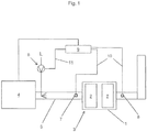
- Fig. 1 shows an internal combustion engine 4, in the exhaust pipe 5, an exhaust gas purification system 3 is arranged.
- the exhaust gas purification system 3 comprises a catalytic converter 1, which in this example is equipped with two catalyst beds 2.
- a flushing device 6 is arranged, through which air L can be introduced into the exhaust gas line 5 upstream of the exhaust gas purification system 3 for flushing the exhaust gas purification system 3.
- the purging of the exhaust gas purification system 3 is carried out as a function of a determined temperature T of the catalyst beds 2 of the catalytic converter 1.
- two temperature detection devices 7, 8 are arranged upstream and downstream of the exhaust gas purification system 3 in this example.
- the temperature detecting means 7 detects the temperature of the exhaust gas of the internal combustion engine 4.
- the temperature detecting means 7 detects a first exhaust gas temperature value T 1 upstream of the catalytic converter 1 and the temperature detecting means 8 detects a second exhaust gas temperature T 2 downstream of the catalytic converter 1.
- the signal lines 10 determine Exhaust gas temperature values T 1 , T 2 are reported to a control device 9, which determines an estimated temperature T of the catalyst beds 2 from the first exhaust gas temperature value T 1 and the second exhaust gas temperature value T 2 .
- This determination of the temperature T of the catalyst beds 2 can take place, for example, by calculating the arithmetic mean value from the first exhaust gas temperature value T 1 and the second exhaust gas temperature T 2 , or, for example, carrying out further calculations taking into account the caloric influencing variables, the response times of the measurement signal chains and the operating history.
- the control device 9 can activate the flushing device 6 via a control line 11 in order to introduce air L upstream of the exhaust gas purification system 3 into the exhaust gas line 5 and thereby flush the exhaust gas purification system 3.
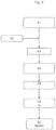
- Fig. 2 1 shows by way of example a flowchart for the purging of the exhaust gas purification system 3 after the engine 4 has been switched off.
- step S1 in which the internal combustion engine is running and supplying exhaust gas to the exhaust gas purification system 3, whereby the exhaust gas purification system 3 is in an active operating phase, step S2 is entered Stop command for stopping the internal combustion engine 4 a.
- step S3 therefore, the internal combustion engine 4 is stopped.
- no further exhaust gas of the internal combustion engine 4 is supplied to the exhaust gas purification system 3 and the exhaust gas purification system 3 is in a passive operating phase in step S4.
- step S5 the temperature T of the at least one catalyst bed 2 of the catalytic converter 1 of the exhaust gas purification system 3 is now determined in step S5.
- step S6 a time period t p is determined, depending on the determined temperature T of the at least one catalyst bed 2, during which the exhaust gas purification system 3 is purged in step S7.
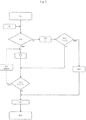
- Fig. 3 shows by way of example a flowchart for the purging of the exhaust gas purification system 3 before the start-up of the internal combustion engine 4.
- step S8 is here of a passive Operating phase of the exhaust purification system 3 is assumed, which may be caused by the fact that the internal combustion engine 4 is not running.
- step S9 the start command for starting the internal combustion engine 4 is performed.
- step S10 it is checked whether the start command has been preceded by a false start of the internal combustion engine 4 or if the internal combustion engine 4 has been shut down beforehand (eg within a predeterminable period of time).
- step S11 the temperature T of the at least one catalyst bed 2 of the catalytic converter 1 of the exhaust gas purification system 3 is determined in step S11.
- step S12 it is checked whether the determined temperature T of the exhaust gas purification system 3 at least one catalyst bed 2 is less than or equal to a setpoint temperature value T S. If this is not the case and thus the temperature T is greater than the setpoint temperature value T S , the exhaust gas purification system 3 is purged in step S13 and the determination of the temperature T of the at least one catalyst bed 2 is continued in step S11.
- step S12 If it turns out in the check in step S12 that the temperature T of the at least one catalyst bed 2 is less than or equal to the setpoint temperature T S , the internal combustion engine 4 can be started in step S14.
- the exhaust gas purification system 3 By starting the engine 4, the exhaust gas purification system 3, an exhaust gas of the internal combustion engine 4 is supplied and the exhaust gas purification system 3 is in step S15 in an active phase of operation.
- step S10 If it is determined in step S10 that a false start of the internal combustion engine 4 has preceded or the internal combustion engine 4 has recently been switched off beforehand, the temperature T of the at least one catalyst bed 2 is determined in step S16 and it is checked in step S17 whether the temperature T of at least a catalyst bed 2 is greater than or equal to a threshold T T. If this is the case and therefore the temperature T is greater than or equal to the threshold value T T , the process continues in step S12. If this is not the case and thus the temperature T is smaller than the threshold value T T , a safety flushing of the exhaust gas purification system 3 is carried out in step S 18.
- the exhaust gas purification system 3 can be purged depending on the size of the exhaust tract for a fixed predetermined period of time, for example 30 to 225 seconds. After this safety purge in step S18, step S14 (starting of the engine 4) is continued.
Landscapes
- Engineering & Computer Science (AREA)
- Chemical & Material Sciences (AREA)
- Chemical Kinetics & Catalysis (AREA)
- Combustion & Propulsion (AREA)
- Mechanical Engineering (AREA)
- General Engineering & Computer Science (AREA)
- Health & Medical Sciences (AREA)
- Toxicology (AREA)
- Exhaust Gas After Treatment (AREA)
- Exhaust Gas Treatment By Means Of Catalyst (AREA)
Description
- Die Erfindung betrifft ein Verfahren zum Spülen eines einen katalytischen Konverter mit wenigstens einem Katalysatorbett umfassenden Abgasreinigungssystems einer Brennkraftmaschine, wobei in einer aktiven Betriebsphase des Abgasreinigungssystems dem Abgasreinigungssystem ein Abgas der Brennkraftmaschine zugeführt wird und in einer passiven Betriebsphase des Abgasreinigungssystems dem Abgasreinigungssystem kein Abgas zugeführt wird, wobei eine Temperatur des wenigstens einen Katalysatorbetts ermittelt wird und das Spülen in Abhängigkeit von der ermittelten Temperatur erfolgt. Verfahren zum Spülen eines in einem Abgasreinigungssystem einer Brennkraftmaschine verbauten katalytischen Konverters mit wenigstens einem Katalysatorbett sind bereits bekannt, um während des Betriebs der Brennkraftmaschine ein sich zu stark erwärmendes Katalysatorbett wieder abzukühlen, sodass ein Überhitzen und eine damit einhergehende Beschädigung des Katalysatorbetts verhindert werden kann (z. B.
DE 2401287 ,EP 1033480 A1 ). DieDE 102 35 194 A1 offenbart ein Verfahren und Vorrichtung zum Betreiben eines Verbrennungsmotors. - Versuche der Anmelderin haben gezeigt, dass nach dem Abschalten einer Brennkraftmaschine, beispielsweise eines stationären Hubkolben-Gasmotors, die Abgastemperatur stromabwärts einer Abgasturbine eines Turboladers auf bis zu mehr als 400 °C ansteigen kann. Dieses Ansteigen der Abgastemperatur führt zu einer Erwärmung eines im Abgasreinigungssystem angeordneten katalytischen Konverters. Wenn nun die Brennkraftmaschine erneut gestartet werden soll, jedoch einen Fehlstart erleidet, so sind die Abgasleitungen und somit auch das Abgasreinigungssystem mitsamt dem katalytischen Konverter mit einem Brenngas-Luft- Gemisch gefüllt. Abhängig von der Temperatur des Katalysatorbetts des katalytischen Konverters und der Anzahl von nicht erfolgreichen Startversuchen in Serie kann es zu unerwünschter Oxidation des Brenngases kommen, wodurch Beschädigungen des katalytischen Konverters und im schlimmsten Fall sogar eine Verpuffung hervorgerufen werden können. Aufgabe der Erfindung ist es daher, ein gegenüber dem Stand der Technik verbessertes Verfahren zum Spülen eines einen katalytischen Konverters mit wenigstens einem Katalysatorbett umfassenden Abgasreinigungssystems einer Brennkraftmaschine anzugeben, durch das ein sichereres Hochfahren der Brennkraftmaschine erzielt werden kann.
- Diese Aufgabe wird erfindungsgemäß durch ein Verfahren mit den Merkmalen des Anspruchs 1 gelöst. Vorteilhafte Ausgestaltungen der Erfindung sind in den abhängigen Ansprüchen angegeben.
- Gemäß der Erfindung ist also vorgesehen, dass das Abgasreinigungssystem in der passiven Betriebsphase des Abgasreinigungssystems gespült wird.
- In Bezug auf das Abgasreinigungssystem werden grundsätzlich zwei Arten von Betriebsphasen unterschieden. Eine aktive Betriebsphase des Abgasreinigungssystems ist dadurch charakterisiert, dass dem Abgasreinigungssystem ein Abgas der Brennkraftmaschine zugeführt wird. Eine passive Betriebsphase des Abgasreinigungssystems ist dadurch charakterisiert, dass dem Abgasreinigungssystem kein Abgas zugeführt wird. Während des laufenden Betriebs einer Brennkraftmaschine, während dessen dem Abgasreinigungssystem ein Abgas der Brennkraftmaschine zugeführt wird, befindet sich somit das Abgasreinigungssystem in einer aktiven Betriebsphase.
- Durch das Spülen des Abgasreinigungssystems in einer passiven Betriebsphase des Abgasreinigungssystems kann ein Einfluss auf das Abgasreinigungssystem auch außerhalb einer aktiven Betriebsphase des Abgasreinigungssystems genommen werden. Insbesondere kann damit eine Überhitzung des katalytischen Konverters bzw. dessen Katalysatorbetten nach dem Abschalten einer Brennkraftmaschine oder vor dem Hochfahren einer Brennkraftmaschine nach vorhergehenden Fehlstarts vermieden werden.
- Ein Spülen des Abgasreinigungssystemes kann durch eine Spülvorrichtung ausgeführt werden, welche über einen eigenen Antrieb verfügt. Dies hat den wesentlichen Vorteil, dass eine Spülung des Abgasreinigungssystemes unabhängig vom Betriebszustand der Brennkraftmaschine durchgeführt werden kann. Dadurch wird es ermöglicht auch eine Spülung vorzunehmen, wenn die Brennkraftmaschine sich in einem passiven Betriebszustand befindet. Auch die Nachteile, wie bei Verwendung eines elektrischen Turboladers als Spülvorrichtung, der die Brennkraftmaschine zwangsweise mitgekühlt, wird dadurch beseitigt. Da, durch eine separat angetriebene Spülvorrichtung lediglich das Abgasreinigungssystem gespült wird und somit auch gekühlt wird, kommt es zu keiner ungewollten Auskühlung der Brennkraftmaschine. Ein solcher separater Antrieb der Spülvorrichtung kann beispielsweise durch einen Elektromotor ausgeführt sein
- In einer bevorzugten Ausführungsform kann vorgesehen sein, dass das Abgasreinigungssystem nur in der passiven Betriebsphase des Abgasreinigungssystems gespült wird. Mit anderen Worten erfolgt hierbei das Spülen des Abgasreinigungssystems ausschließlich in den passiven Betriebsphasen des Abgasreinigungssystems, in denen dem Abgasreinigungssystem kein Abgas zugeführt wird. Vorzugsweise kann vorgesehen sein, dass die Temperatur des wenigstens einen Katalysatorbetts in der passiven Betriebsphase des Abgasreinigungssystems ermittelt wird.
- Erfindungsgemäß ist vorgesehen, dass das Abgasreinigungssystem nach einem Abschalten der Brennkraftmaschine gespült wird. Dadurch wird ein im Abgastrakt gegebenenfalls noch vorhandenes brennbares Brennstoff-Luft-Gemisch aus dem Abgastrakt entfernt, bevor erneut ein Start der Brennkraftmaschine durchgeführt wird. Eine besondere Ausführungsvariante sieht vor, dass abhängig von der ermittelten Temperatur eine Zeitdauer ermittelt wird, während der das Abgasreinigungssystem gespült wird. Bei der Bestimmung der Zeitdauer kann dabei berücksichtigt werden, dass bei einem heißen Katalysator bzw. Katalysatorbett länger als bei einem kälteren Katalysator bzw. Katalysatorbett zu spülen ist, um sicherzugehen, dass kein brennbares Brennstoff-Luft-Gemisch mehr im Abgastrakt vorhanden ist.
- Gemäß einer besonders bevorzugten Ausführungsform kann vorgesehen sein, dass das Abgasreinigungssystem vor einem Hochfahren der Brennkraftmaschine gespült wird. Dadurch kann sichergestellt werden, dass beim Hochfahren der Brennkraftmaschine im Abgastrakt kein brennbares Brennstoff-Luft-Gemisch mehr vorhanden ist, das durch unerwünschte Oxidation im katalytischen Konverter Beschädigungen des katalytischen Konverters verursachen kann.
- Als besonders vorteilhaft hat es sich herausgestellt, wenn das Abgasreinigungssystem so lange gespült wird, bis die Temperatur des wenigstens einen Katalysatorbetts kleiner oder gleich einer vorgebbaren Solltemperatur ist. Die vorgebbare Solltemperatur kann dabei vorzugsweise so gewählt werden, dass unterhalb der vorgebbaren Solltemperatur vom katalytischen Konverter kein nennenswertes Risiko mehr ausgeht, als Zündquelle zu dienen. Die vorgebbare Solltemperatur kann je nach Dimensionierung des katalytischen Konverters und der verwendeten Brenngasqualität in einem Bereich von etwa 200°C bis etwa 400°C liegen, beispielsweise bei etwa 300°C.
- Dabei kann vorgesehen sein, dass das Abgasreinigungssystem gespült wird, falls die Temperatur des wenigstens einen Katalysatorbetts vor dem Spülen größer oder gleich einem vorgebbaren Schwellwert ist. Der vorgebbare Schwellwert kann dabei vorzugsweise so gewählt werden, dass unterhalb des vorgebbaren Schwellwerts vom katalytischen Konverter kein nennenswertes Risiko mehr ausgeht, als Zündquelle zu dienen. Der vorgebbare Schwellwert kann je nach Dimensionierung des katalytischen Konverters in einem Bereich von etwa 200°C bis etwa 400°C liegen, beispielsweise bei etwa 300°C.
- Für den Fall, dass die Temperatur des wenigstens einen Katalysatorbetts kleiner dem vorgebbaren Schwellwert ist, kann vorgesehen sein, dass ein sogenanntes Sicherheitsspülen für eine vorgebbare Zeitdauer erfolgt, die je nach Größe des Abgastraktes in einem Bereich von etwa 30 Sekunden bis etwa 225 Sekunden liegen kann.
- Bei einer weiteren bevorzugten Ausführungsform kann vorgesehen sein, dass ein erster Abgastemperaturwert stromaufwärts des katalytischen Konverters ermittelt wird und ein zweiter Abgastemperaturwert stromabwärts des katalytischen Konverters ermittelt wird, wobei die Temperatur des wenigstens einen Katalysatorbetts unter Berücksichtigung des ersten Abgastemperaturwerts und des zweiten Abgastemperaturwerts ermittelt wird.
- Vorzugsweise kann vorgesehen sein, dass das Abgasreinigungssystem mit Luft gespült wird.
- Weitere Einzelheiten und Vorteile der vorliegenden Erfindung werden anhand der Figurenbeschreibung unter Bezugnahme auf die in den Zeichnungen dargestellten Ausführungsbeispiele im Folgenden näher erläutert. Darin zeigen:
- Fig. 1
- eine Brennkraftmaschine mit einem Abgasreinigungssystem,
- Fig. 2
- ein Ablaufdiagramm bezüglich des Spülens eines Abgasreinigungssystems nach dem Abschalten einer Brennkraftmaschine,
- Fig. 3
- ein Ablaufdiagramm in Bezug auf das Spülen eines Abgasreinigungssystems vor dem Hochfahren einer Brennkraftmaschine.
-
Fig. 1 zeigt eine Brennkraftmaschine 4, in deren Abgasleitung 5 ein Abgasreinigungssystem 3 angeordnet ist. Bei der Brennkraftmaschine 4 handelt es sich in diesem Beispiel um einen stationären Gasmotor, der mit einem Brenngas-Luft-Gemisch betrieben wird. Das Abgasreinigungssystem 3 umfasst einen katalytischen Konverter 1, der in diesem Beispiel mit zwei Katalysatorbetten 2 ausgestattet ist. Stromaufwärts des Abgasreinigungssystems 3 ist eine Spülvorrichtung 6 angeordnet, durch die Luft L in die Abgasleitung 5 stromaufwärts des Abgasreinigungssystems 3 zum Spülen des Abgasreinigungssystems 3 eingebracht werden kann. - Gemäß dem vorgeschlagenen Verfahren erfolgt das Spülen des Abgasreinigungssystems 3 in Abhängigkeit einer ermittelten Temperatur T der Katalysatorbetten 2 des katalytischen Konverters 1. Zur Ermittlung der Temperatur T sind in diesem Beispiel zwei Temperaturerfassungseinrichtungen 7, 8 stromaufwärts und stromabwärts des Abgasreinigungssystems 3 angeordnet. Die Temperaturerfassungseinrichtungen 7, 8 ermitteln die Temperatur des Abgases der Brennkraftmaschine 4. Die Temperaturerfassungseinrichtung 7 erfasst einen ersten Abgastemperaturwert T1 stromaufwärts des katalytischen Konverters 1 und die Temperaturerfassungseinrichtung 8 ermittelt einen zweiten Abgastemperaturwert T2 stromabwärts des katalytischen Konverters 1. Über Signalleitungen 10 werden die ermittelten Abgastemperaturwerte T1, T2 an eine Steuervorrichtung 9 gemeldet, die aus dem ersten Abgastemperaturwert T1 und dem zweiten Abgastemperaturwert T2 eine geschätzte Temperatur T der Katalysatorbetten 2 ermittelt. Diese Ermittlung der Temperatur T der Katalysatorbetten 2 kann beispielsweise dadurch erfolgen, dass der arithmetische Mittelwert aus erstem Abgastemperaturwert T1 und zweitem Abgastemperaturwert T2 berechnet wird oder beispielsweise auch weitergehende Berechnungen unter Berücksichtigung der kalorischen Einflussgrößen, der Ansprechzeiten der Messsignalketten und der Betriebshistorie vorgenommen werden. In Abhängigkeit von der ermittelten Temperatur T kann die Steuervorrichtung 9 über eine Steuerleitung 11 die Spülvorrichtung 6 aktivieren, um Luft L stromaufwärts des Abgasreinigungssystems 3 in die Abgasleitung 5 einzubringen und dadurch das Abgasreinigungssystem 3 zu spülen.
-
Fig. 2 zeigt beispielhaft ein Ablaufdiagramm für das Spülen des Abgasreinigungssystems 3 nach dem Abschalten der Brennkraftmaschine 4. Ausgehend von Schritt S1, in dem die Brennkraftmaschine läuft und dem Abgasreinigungssystem 3 Abgas zuführt, wodurch das Abgasreinigungssystem 3 sich in einer aktiven Betriebsphase befindet, geht in Schritt S2 ein Stopp-Befehl zum Stoppen der Brennkraftmaschine 4 ein. In Schritt S3 wird demnach die Brennkraftmaschine 4 gestoppt. Dadurch wird dem Abgasreinigungssystem 3 kein weiteres Abgas der Brennkraftmaschine 4 mehr zugeführt und das Abgasreinigungssystem 3 befindet sich in Schritt S4 in einer passiven Betriebsphase. In dieser passiven Betriebsphase des Abgasreinigungssystems 3 wird nunmehr in Schritt S5 die Temperatur T des wenigstens einen Katalysatorbetts 2 des katalytischen Konverters 1 des Abgasreinigungssystems 3 ermittelt. In Schritt S6 wird abhängig von der ermittelten Temperatur T des wenigstens einen Katalysatorbetts 2 eine Zeitdauer tp ermittelt, während der in Schritt S7 das Abgasreinigungssystem 3 gespült wird. -
Fig. 3 zeigt beispielhaft ein Ablaufdiagramm für das Spülen des Abgasreinigungssystems 3 vor dem Hochfahren der Brennkraftmaschine 4. In Schritt S8 wird hier von einer passiven Betriebsphase des Abgasreinigungssystems 3 ausgegangen, die dadurch hervorgerufen sein kann, dass die Brennkraftmaschine 4 nicht läuft. In Schritt S9 erfolgt der Startbefehl zum Starten der Brennkraftmaschine 4. In Schritt S10 wird abgeprüft, ob dem Startbefehl ein Fehlstart der Brennkraftmaschine 4 vorausgegangen ist oder ob die Brennkraftmaschine 4 zuvor (z. B. innerhalb eines vorgebbaren Zeitraums) abgeschaltet wurde. Falls kein Fehlstart vorangegangen ist und die Brennkraftmaschine 4 nicht kürzlich zuvor abgeschaltet wurde, so erfolgt in Schritt S11 die Ermittlung der Temperatur T des wenigstens einen Katalysatorbetts 2 des katalytischen Konverters 1 des Abgasreinigungssystems 3. In Schritt S12 wird überprüft, ob die ermittelte Temperatur T des wenigstens einen Katalysatorbetts 2 kleiner oder gleich einem Solltemperaturwert TS ist. Falls dies nicht der Fall ist und also die Temperatur T größer als der Solltemperaturwert TS ist, so wird in Schritt S13 das Abgasreinigungssystem 3 gespült und bei Schritt S11, der Ermittlung der Temperatur T des wenigstens einen Katalysatorbetts 2, fortgesetzt. Falls sich bei der Überprüfung in Schritt S12 herausstellt, dass die Temperatur T des wenigstens einen Katalysatorbetts 2 kleiner oder gleich der Solltemperatur TS ist, so kann in Schritt S14 die Brennkraftmaschine 4 gestartet werden. Durch das Starten der Brennkraftmaschine 4 wird dem Abgasreinigungssystem 3 ein Abgas der Brennkraftmaschine 4 zugeführt und das Abgasreinigungssystem 3 befindet sich in Schritt S15 in einer aktiven Betriebsphase. - Falls in Schritt S10 festgestellt wird, dass ein Fehlstart der Brennkraftmaschine 4 vorausgegangen ist oder die Brennkraftmaschine 4 kürzlich zuvor abgeschaltet wurde, so wird in Schritt S16 die Temperatur T des wenigstens einen Katalysatorbetts 2 ermittelt und in Schritt S17 überprüft, ob die Temperatur T des wenigstens einen Katalysatorbetts 2 größer oder gleich einem Schwellwert TT ist. Falls dies der Fall ist und also die Temperatur T größer oder gleich dem Schwellwert TT ist, so wird in Schritt S12 fortgesetzt. Falls dies nicht der Fall ist und also die Temperatur T kleiner als der Schwellwert TT ist, so wird in Schritt S18 ein Sicherheitsspülen des Abgasreinigungssystems 3 durchgeführt. Dabei kann das Abgasreinigungssystem 3 je nach Größe des Abgastraktes für eine fix vorgegebene Zeitdauer von beispielsweise 30 bis 225 Sekunden gespült werden. Nach diesem Sicherheitsspülen in Schritt S18 wird mit Schritt S14 (Starten der Brennkraftmaschine 4) fortgesetzt.
Claims (8)
- Verfahren zum Spülen eines einen katalytischen Konverter (1) mit wenigstens einem Katalysatorbett (2) umfassenden Abgasreinigungssystems (3) einer Brennkraftmaschine (4), wobei in einer aktiven Betriebsphase des Abgasreinigungssystems (3) dem Abgasreinigungssystem (3) ein Abgas der Brennkraftmaschine (4) zugeführt wird und in einer passiven Betriebsphase des Abgasreinigungssystems (3) dem Abgasreinigungssystem (3) kein Abgas zugeführt wird, wobei eine Temperatur (T) des wenigstens einen Katalysatorbetts (2) ermittelt wird und das Spülen in Abhängigkeit von der ermittelten Temperatur (T) erfolgt, wobei das Abgasreinigungssystem (3) in der passiven Betriebsphase des Abgasreinigungssystems (3) durch eine Spülvorrichtung (6), welche unmittelbar mit einer Abgasleitung (5) verbunden ist, gespült wird, dadurch gekennzeichnet, dass das Abgasreinigungssystem (3) vor einem Hochfahren der Brennkraftmaschine (4) gespült wird und das Verfahren in einer passiven Betriebsphase des Abgasreinigungssystems (3) abprüft, ob einem Startbefehl zum Starten der Brennkraftmaschine (4) ein Fehlstart vorausgegangen ist oder ob die Brennkraftmaschine (4) zuvor abgeschaltet wurde.
- Verfahren nach Anspruch 1 , dadurch gekennzeichnet, dass das Abgasreinigungssystem (3) nur in der passiven Betriebsphase des Abgasreinigungssystems (3) gespült wird.
- Verfahren nach Anspruch 1 oder 2, dadurch gekennzeichnet, dass die Temperatur (T) des wenigstens einen Katalysatorbetts (2) in der passiven Betriebsphase des Abgasreinigungssystems (3) ermittelt wird.
- Verfahren nach einem der Ansprüche 1 bis 3, dadurch gekennzeichnet, dass das Abgasreinigungssystem (3) nach einem Abschalten der Brennkraftmaschine (4) gespült wird.
- Verfahren nach einem der Ansprüche 1 bis 4, dadurch gekennzeichnet, dass abhängig von der ermittelten Temperatur (T) eine Zeitdauer (tp) ermittelt wird, während der das Abgasreinigungssystem (3) gespült wird.
- Verfahren nach einem der Ansprüche 1 bis 5, dadurch gekennzeichnet, dass das Abgasreinigungssystem (3) so lange gespült wird, bis die Temperatur (T) des wenigstens einen Katalysatorbetts (2) kleiner oder gleich einer vorgebbaren Solltemperatur (TS) ist.
- Verfahren nach Anspruch 6, dadurch gekennzeichnet, dass das Abgasreinigungssystem (3) gespült wird, falls die Temperatur (T) des wenigstens einen Katalysatorbetts (2) vor dem Spülen größer oder gleich einem vorgebbaren Schwellwert (TT) ist.
- Verfahren nach einem der Ansprüche 1 bis 7, dadurch gekennzeichnet, dass ein erster Abgastemperaturwert (Ti) stromaufwärts des katalytischen Konverters (1) ermittelt wird und ein zweiter Abgastemperaturwert (T2) stromabwärts des katalytischen Konverters (1) ermittelt wird, wobei die Temperatur (T) des wenigstens einen Katalysatorbetts (2) unter Berücksichtigung des ersten Abgastemperaturwerts (Ti) und des zweiten Abgastemperaturwerts (T2) ermittelt wird.
Applications Claiming Priority (2)
| Application Number | Priority Date | Filing Date | Title |
|---|---|---|---|
| ATA50384/2015A AT517166B1 (de) | 2015-05-11 | 2015-05-11 | Verfahren zum Spülen eines Abgasreinigungssystems |
| PCT/AT2016/050135 WO2016179623A1 (de) | 2015-05-11 | 2016-05-09 | Verfahren zum spülen eines abgasreinigungssystems |
Publications (2)
| Publication Number | Publication Date |
|---|---|
| EP3295001A1 EP3295001A1 (de) | 2018-03-21 |
| EP3295001B1 true EP3295001B1 (de) | 2019-07-03 |
Family
ID=56403915
Family Applications (1)
| Application Number | Title | Priority Date | Filing Date |
|---|---|---|---|
| EP16736765.5A Active EP3295001B1 (de) | 2015-05-11 | 2016-05-09 | Verfahren zum spülen eines abgasreinigungssystems |
Country Status (5)
| Country | Link |
|---|---|
| US (1) | US20180135484A1 (de) |
| EP (1) | EP3295001B1 (de) |
| CN (1) | CN107636270B (de) |
| AT (1) | AT517166B1 (de) |
| WO (1) | WO2016179623A1 (de) |
Families Citing this family (1)
| Publication number | Priority date | Publication date | Assignee | Title |
|---|---|---|---|---|
| US11624333B2 (en) | 2021-04-20 | 2023-04-11 | Kohler Co. | Exhaust safety system for an engine |
Family Cites Families (12)
| Publication number | Priority date | Publication date | Assignee | Title |
|---|---|---|---|---|
| FR2166504A5 (de) * | 1971-12-28 | 1973-08-17 | Peugeot & Renault | |
| JPS5232019B2 (de) | 1973-01-13 | 1977-08-18 | ||
| EP1033480A1 (de) | 1999-02-17 | 2000-09-06 | Man Nutzfahrzeuge Ag | Verfahren zur Dosierung eines Reduktionsmittels in stickoxidhaltiges Abgas einer Brennkraftmaschine |
| JP3695397B2 (ja) * | 2001-04-10 | 2005-09-14 | トヨタ自動車株式会社 | 内燃機関の排気浄化装置 |
| JP2005517852A (ja) * | 2002-02-14 | 2005-06-16 | ロベルト・ボッシュ・ゲゼルシャフト・ミト・ベシュレンクテル・ハフツング | 内燃機関の運転方法および装置 |
| DE10235194A1 (de) * | 2002-02-14 | 2003-08-28 | Bosch Gmbh Robert | Verfahren und Vorrichtung zum Betreiben eines Verbrennungsmotors |
| JP3824979B2 (ja) * | 2002-08-09 | 2006-09-20 | ボッシュ株式会社 | フィルタ制御方法及び装置 |
| JP4525564B2 (ja) * | 2005-11-16 | 2010-08-18 | トヨタ自動車株式会社 | 内燃機関 |
| DE602006015766D1 (de) * | 2006-01-16 | 2010-09-09 | Ford Global Tech Llc | Verfahren und Anordnung für Kühlung eines Abgassystems |
| JP2007262919A (ja) * | 2006-03-27 | 2007-10-11 | Mitsubishi Motors Corp | 内燃機関の制御装置 |
| JP2010511838A (ja) * | 2006-12-05 | 2010-04-15 | マック トラックス インコーポレイテッド | 排気冷却を有するエンジン及びその方法 |
| US8931265B2 (en) * | 2012-05-10 | 2015-01-13 | GM Global Technology Operations LLC | Closed loop temperature control in the SCR warm up mode to reduce emission variation |
-
2015
- 2015-05-11 AT ATA50384/2015A patent/AT517166B1/de not_active IP Right Cessation
-
2016
- 2016-05-09 US US15/573,264 patent/US20180135484A1/en not_active Abandoned
- 2016-05-09 WO PCT/AT2016/050135 patent/WO2016179623A1/de not_active Ceased
- 2016-05-09 CN CN201680027453.0A patent/CN107636270B/zh active Active
- 2016-05-09 EP EP16736765.5A patent/EP3295001B1/de active Active
Non-Patent Citations (1)
| Title |
|---|
| None * |
Also Published As
| Publication number | Publication date |
|---|---|
| EP3295001A1 (de) | 2018-03-21 |
| WO2016179623A1 (de) | 2016-11-17 |
| CN107636270A (zh) | 2018-01-26 |
| AT517166A1 (de) | 2016-11-15 |
| AT517166B1 (de) | 2017-05-15 |
| US20180135484A1 (en) | 2018-05-17 |
| CN107636270B (zh) | 2020-07-28 |
Similar Documents
| Publication | Publication Date | Title |
|---|---|---|
| DE19732167C2 (de) | Abgasreinigungsvorrichtung für Verbrennungsmotoren | |
| EP3292291B1 (de) | Wassereinspritzvorrichtung einer brennkraftmaschine und verfahren zum betreiben einer solchen wassereinspritzvorrichtung | |
| DE102019215698B3 (de) | Verfahren zum Vorheizen eines Katalysators | |
| DE102008005525A1 (de) | Verfahren zum Start einer Brennkraftmaschine mit Start-Stopp-Funktion | |
| DE102013200487B4 (de) | Abgasströmungssystem zum Detektieren eines thermischen Ereignisses in einem Abgassystem auf Grundlage von Temperaturgradienten | |
| EP1582709A2 (de) | Regenerationsverfahren für ein Partikelfilter sowie Abgasanlage mit Partikelfilter | |
| DE10303911A1 (de) | Verfahren zur Überwachung des Anspringverhaltens eines Abgaskatalysatorsystems | |
| DE102013001319B4 (de) | Verfahren zum Betreiben einer Brennkraftmaschine sowie entsprechende Brennkraftmaschine | |
| WO2016179623A1 (de) | Verfahren zum spülen eines abgasreinigungssystems | |
| DE4433632A1 (de) | Verfahren zur Überwachung einer Heizeinrichtung eines im Abgassystem einer Brennkraftmaschine angebrachten Sensors | |
| DE10213170A1 (de) | Betriebsverfahren für eine mit einem Abgasnachbehandlungssystem arbeitende Brennkraftmaschine | |
| DE102012222868B4 (de) | Diagnose der Funktionsfähigkeit eines Sekundärluftsystems einer Brennkraftmaschine | |
| EP3066326B1 (de) | Verfahren zur erkennung von defekten einspritzdüsen eines verbrennungsmotors | |
| DE102020215514A1 (de) | Verfahren zum Betreiben einer Abgasnachbehandlungsanlage, Abgasnachbehandlungsanlage sowie Verbrennungsmotor | |
| DE69404095T2 (de) | Abgasreiniger | |
| EP2180179A2 (de) | Verfahren zum Betreiben einer Brennkraftmaschine und Vorrichtung zur Durchführung des Verfahrens | |
| DE102009029586A1 (de) | Verfahren und Steuervorrichtung zum Betreiben einer Brennkraftmaschine | |
| DE60120324T2 (de) | Brennstoffheizvorrichtung und Steurerung | |
| WO2009068431A1 (de) | Verfahren und vorrichtung zur fehlererkennung bei emissionsrelevanten steuereinrichtungen in einem fahrzeug | |
| EP1517011A2 (de) | Abgasanlage mit Partikelfilter sowie zugehörige Heizeinrichtung und zugehöriges Regenerationsverfahren | |
| DE102019216509B3 (de) | Verfahren zum Starten einer Brennkraftmaschine sowie Brennkraftmaschine zur Durchführung eines solchen Verfahrens | |
| DE102014000871B3 (de) | Verfahren zum Betreiben einer Brennkraftmaschine sowie entsprechende Brennkraftmaschine | |
| DE102020110205A1 (de) | Verfahren zum Starten einer Verbrennungskraftmaschine eines Kraftfahrzeugs, insbesondere eines Kraftwagens | |
| DE102013213235B4 (de) | Verfahren zur Erkennung von defekten Einspritzdüsen eines Verbrennungsmotors | |
| DE102006015351A1 (de) | Verfahren zur Regelung der Temperatur einer Zündspule eines Kraftfahrzeugs |
Legal Events
| Date | Code | Title | Description |
|---|---|---|---|
| STAA | Information on the status of an ep patent application or granted ep patent |
Free format text: STATUS: THE INTERNATIONAL PUBLICATION HAS BEEN MADE |
|
| PUAI | Public reference made under article 153(3) epc to a published international application that has entered the european phase |
Free format text: ORIGINAL CODE: 0009012 |
|
| STAA | Information on the status of an ep patent application or granted ep patent |
Free format text: STATUS: REQUEST FOR EXAMINATION WAS MADE |
|
| 17P | Request for examination filed |
Effective date: 20171211 |
|
| AK | Designated contracting states |
Kind code of ref document: A1 Designated state(s): AL AT BE BG CH CY CZ DE DK EE ES FI FR GB GR HR HU IE IS IT LI LT LU LV MC MK MT NL NO PL PT RO RS SE SI SK SM TR |
|
| AX | Request for extension of the european patent |
Extension state: BA ME |
|
| DAV | Request for validation of the european patent (deleted) | ||
| DAX | Request for extension of the european patent (deleted) | ||
| REG | Reference to a national code |
Ref country code: DE Ref legal event code: R079 Ref document number: 502016005392 Country of ref document: DE Free format text: PREVIOUS MAIN CLASS: F01N0003200000 Ipc: F01N0003040000 |
|
| GRAP | Despatch of communication of intention to grant a patent |
Free format text: ORIGINAL CODE: EPIDOSNIGR1 |
|
| STAA | Information on the status of an ep patent application or granted ep patent |
Free format text: STATUS: GRANT OF PATENT IS INTENDED |
|
| RIC1 | Information provided on ipc code assigned before grant |
Ipc: F01N 11/00 20060101ALI20190118BHEP Ipc: F01N 3/20 20060101ALI20190118BHEP Ipc: F01N 3/04 20060101AFI20190118BHEP |
|
| INTG | Intention to grant announced |
Effective date: 20190214 |
|
| GRAS | Grant fee paid |
Free format text: ORIGINAL CODE: EPIDOSNIGR3 |
|
| RAP1 | Party data changed (applicant data changed or rights of an application transferred) |
Owner name: INNIO JENBACHER GMBH & CO OG |
|
| GRAA | (expected) grant |
Free format text: ORIGINAL CODE: 0009210 |
|
| STAA | Information on the status of an ep patent application or granted ep patent |
Free format text: STATUS: THE PATENT HAS BEEN GRANTED |
|
| AK | Designated contracting states |
Kind code of ref document: B1 Designated state(s): AL AT BE BG CH CY CZ DE DK EE ES FI FR GB GR HR HU IE IS IT LI LT LU LV MC MK MT NL NO PL PT RO RS SE SI SK SM TR |
|
| REG | Reference to a national code |
Ref country code: GB Ref legal event code: FG4D Free format text: NOT ENGLISH |
|
| REG | Reference to a national code |
Ref country code: CH Ref legal event code: EP Ref country code: AT Ref legal event code: REF Ref document number: 1151264 Country of ref document: AT Kind code of ref document: T Effective date: 20190715 |
|
| REG | Reference to a national code |
Ref country code: IE Ref legal event code: FG4D Free format text: LANGUAGE OF EP DOCUMENT: GERMAN |
|
| REG | Reference to a national code |
Ref country code: DE Ref legal event code: R096 Ref document number: 502016005392 Country of ref document: DE |
|
| REG | Reference to a national code |
Ref country code: NL Ref legal event code: MP Effective date: 20190703 |
|
| REG | Reference to a national code |
Ref country code: LT Ref legal event code: MG4D |
|
| PG25 | Lapsed in a contracting state [announced via postgrant information from national office to epo] |
Ref country code: FI Free format text: LAPSE BECAUSE OF FAILURE TO SUBMIT A TRANSLATION OF THE DESCRIPTION OR TO PAY THE FEE WITHIN THE PRESCRIBED TIME-LIMIT Effective date: 20190703 Ref country code: HR Free format text: LAPSE BECAUSE OF FAILURE TO SUBMIT A TRANSLATION OF THE DESCRIPTION OR TO PAY THE FEE WITHIN THE PRESCRIBED TIME-LIMIT Effective date: 20190703 Ref country code: SE Free format text: LAPSE BECAUSE OF FAILURE TO SUBMIT A TRANSLATION OF THE DESCRIPTION OR TO PAY THE FEE WITHIN THE PRESCRIBED TIME-LIMIT Effective date: 20190703 Ref country code: NO Free format text: LAPSE BECAUSE OF FAILURE TO SUBMIT A TRANSLATION OF THE DESCRIPTION OR TO PAY THE FEE WITHIN THE PRESCRIBED TIME-LIMIT Effective date: 20191003 Ref country code: NL Free format text: LAPSE BECAUSE OF FAILURE TO SUBMIT A TRANSLATION OF THE DESCRIPTION OR TO PAY THE FEE WITHIN THE PRESCRIBED TIME-LIMIT Effective date: 20190703 Ref country code: CZ Free format text: LAPSE BECAUSE OF FAILURE TO SUBMIT A TRANSLATION OF THE DESCRIPTION OR TO PAY THE FEE WITHIN THE PRESCRIBED TIME-LIMIT Effective date: 20190703 Ref country code: LT Free format text: LAPSE BECAUSE OF FAILURE TO SUBMIT A TRANSLATION OF THE DESCRIPTION OR TO PAY THE FEE WITHIN THE PRESCRIBED TIME-LIMIT Effective date: 20190703 Ref country code: BG Free format text: LAPSE BECAUSE OF FAILURE TO SUBMIT A TRANSLATION OF THE DESCRIPTION OR TO PAY THE FEE WITHIN THE PRESCRIBED TIME-LIMIT Effective date: 20191003 Ref country code: PT Free format text: LAPSE BECAUSE OF FAILURE TO SUBMIT A TRANSLATION OF THE DESCRIPTION OR TO PAY THE FEE WITHIN THE PRESCRIBED TIME-LIMIT Effective date: 20191104 |
|
| PG25 | Lapsed in a contracting state [announced via postgrant information from national office to epo] |
Ref country code: RS Free format text: LAPSE BECAUSE OF FAILURE TO SUBMIT A TRANSLATION OF THE DESCRIPTION OR TO PAY THE FEE WITHIN THE PRESCRIBED TIME-LIMIT Effective date: 20190703 Ref country code: LV Free format text: LAPSE BECAUSE OF FAILURE TO SUBMIT A TRANSLATION OF THE DESCRIPTION OR TO PAY THE FEE WITHIN THE PRESCRIBED TIME-LIMIT Effective date: 20190703 Ref country code: AL Free format text: LAPSE BECAUSE OF FAILURE TO SUBMIT A TRANSLATION OF THE DESCRIPTION OR TO PAY THE FEE WITHIN THE PRESCRIBED TIME-LIMIT Effective date: 20190703 Ref country code: GR Free format text: LAPSE BECAUSE OF FAILURE TO SUBMIT A TRANSLATION OF THE DESCRIPTION OR TO PAY THE FEE WITHIN THE PRESCRIBED TIME-LIMIT Effective date: 20191004 Ref country code: ES Free format text: LAPSE BECAUSE OF FAILURE TO SUBMIT A TRANSLATION OF THE DESCRIPTION OR TO PAY THE FEE WITHIN THE PRESCRIBED TIME-LIMIT Effective date: 20190703 Ref country code: IS Free format text: LAPSE BECAUSE OF FAILURE TO SUBMIT A TRANSLATION OF THE DESCRIPTION OR TO PAY THE FEE WITHIN THE PRESCRIBED TIME-LIMIT Effective date: 20191103 |
|
| PG25 | Lapsed in a contracting state [announced via postgrant information from national office to epo] |
Ref country code: TR Free format text: LAPSE BECAUSE OF FAILURE TO SUBMIT A TRANSLATION OF THE DESCRIPTION OR TO PAY THE FEE WITHIN THE PRESCRIBED TIME-LIMIT Effective date: 20190703 |
|
| PG25 | Lapsed in a contracting state [announced via postgrant information from national office to epo] |
Ref country code: PL Free format text: LAPSE BECAUSE OF FAILURE TO SUBMIT A TRANSLATION OF THE DESCRIPTION OR TO PAY THE FEE WITHIN THE PRESCRIBED TIME-LIMIT Effective date: 20190703 Ref country code: EE Free format text: LAPSE BECAUSE OF FAILURE TO SUBMIT A TRANSLATION OF THE DESCRIPTION OR TO PAY THE FEE WITHIN THE PRESCRIBED TIME-LIMIT Effective date: 20190703 Ref country code: RO Free format text: LAPSE BECAUSE OF FAILURE TO SUBMIT A TRANSLATION OF THE DESCRIPTION OR TO PAY THE FEE WITHIN THE PRESCRIBED TIME-LIMIT Effective date: 20190703 Ref country code: DK Free format text: LAPSE BECAUSE OF FAILURE TO SUBMIT A TRANSLATION OF THE DESCRIPTION OR TO PAY THE FEE WITHIN THE PRESCRIBED TIME-LIMIT Effective date: 20190703 |
|
| PG25 | Lapsed in a contracting state [announced via postgrant information from national office to epo] |
Ref country code: IS Free format text: LAPSE BECAUSE OF FAILURE TO SUBMIT A TRANSLATION OF THE DESCRIPTION OR TO PAY THE FEE WITHIN THE PRESCRIBED TIME-LIMIT Effective date: 20200224 Ref country code: SK Free format text: LAPSE BECAUSE OF FAILURE TO SUBMIT A TRANSLATION OF THE DESCRIPTION OR TO PAY THE FEE WITHIN THE PRESCRIBED TIME-LIMIT Effective date: 20190703 Ref country code: SM Free format text: LAPSE BECAUSE OF FAILURE TO SUBMIT A TRANSLATION OF THE DESCRIPTION OR TO PAY THE FEE WITHIN THE PRESCRIBED TIME-LIMIT Effective date: 20190703 |
|
| REG | Reference to a national code |
Ref country code: DE Ref legal event code: R097 Ref document number: 502016005392 Country of ref document: DE |
|
| PLBE | No opposition filed within time limit |
Free format text: ORIGINAL CODE: 0009261 |
|
| STAA | Information on the status of an ep patent application or granted ep patent |
Free format text: STATUS: NO OPPOSITION FILED WITHIN TIME LIMIT |
|
| PG2D | Information on lapse in contracting state deleted |
Ref country code: IS |
|
| 26N | No opposition filed |
Effective date: 20200603 |
|
| PG25 | Lapsed in a contracting state [announced via postgrant information from national office to epo] |
Ref country code: SI Free format text: LAPSE BECAUSE OF FAILURE TO SUBMIT A TRANSLATION OF THE DESCRIPTION OR TO PAY THE FEE WITHIN THE PRESCRIBED TIME-LIMIT Effective date: 20190703 |
|
| PG25 | Lapsed in a contracting state [announced via postgrant information from national office to epo] |
Ref country code: LI Free format text: LAPSE BECAUSE OF NON-PAYMENT OF DUE FEES Effective date: 20200531 Ref country code: MC Free format text: LAPSE BECAUSE OF FAILURE TO SUBMIT A TRANSLATION OF THE DESCRIPTION OR TO PAY THE FEE WITHIN THE PRESCRIBED TIME-LIMIT Effective date: 20190703 Ref country code: CH Free format text: LAPSE BECAUSE OF NON-PAYMENT OF DUE FEES Effective date: 20200531 |
|
| REG | Reference to a national code |
Ref country code: BE Ref legal event code: MM Effective date: 20200531 |
|
| PG25 | Lapsed in a contracting state [announced via postgrant information from national office to epo] |
Ref country code: LU Free format text: LAPSE BECAUSE OF NON-PAYMENT OF DUE FEES Effective date: 20200509 |
|
| PG25 | Lapsed in a contracting state [announced via postgrant information from national office to epo] |
Ref country code: IE Free format text: LAPSE BECAUSE OF NON-PAYMENT OF DUE FEES Effective date: 20200509 |
|
| PG25 | Lapsed in a contracting state [announced via postgrant information from national office to epo] |
Ref country code: BE Free format text: LAPSE BECAUSE OF NON-PAYMENT OF DUE FEES Effective date: 20200531 |
|
| PG25 | Lapsed in a contracting state [announced via postgrant information from national office to epo] |
Ref country code: MT Free format text: LAPSE BECAUSE OF FAILURE TO SUBMIT A TRANSLATION OF THE DESCRIPTION OR TO PAY THE FEE WITHIN THE PRESCRIBED TIME-LIMIT Effective date: 20190703 Ref country code: CY Free format text: LAPSE BECAUSE OF FAILURE TO SUBMIT A TRANSLATION OF THE DESCRIPTION OR TO PAY THE FEE WITHIN THE PRESCRIBED TIME-LIMIT Effective date: 20190703 |
|
| PG25 | Lapsed in a contracting state [announced via postgrant information from national office to epo] |
Ref country code: MK Free format text: LAPSE BECAUSE OF FAILURE TO SUBMIT A TRANSLATION OF THE DESCRIPTION OR TO PAY THE FEE WITHIN THE PRESCRIBED TIME-LIMIT Effective date: 20190703 |
|
| REG | Reference to a national code |
Ref country code: AT Ref legal event code: MM01 Ref document number: 1151264 Country of ref document: AT Kind code of ref document: T Effective date: 20210509 |
|
| PG25 | Lapsed in a contracting state [announced via postgrant information from national office to epo] |
Ref country code: AT Free format text: LAPSE BECAUSE OF NON-PAYMENT OF DUE FEES Effective date: 20210509 |
|
| P01 | Opt-out of the competence of the unified patent court (upc) registered |
Effective date: 20230614 |
|
| PGFP | Annual fee paid to national office [announced via postgrant information from national office to epo] |
Ref country code: DE Payment date: 20250423 Year of fee payment: 10 |
|
| PGFP | Annual fee paid to national office [announced via postgrant information from national office to epo] |
Ref country code: GB Payment date: 20250423 Year of fee payment: 10 |
|
| PGFP | Annual fee paid to national office [announced via postgrant information from national office to epo] |
Ref country code: IT Payment date: 20250423 Year of fee payment: 10 |
|
| PGFP | Annual fee paid to national office [announced via postgrant information from national office to epo] |
Ref country code: FR Payment date: 20250423 Year of fee payment: 10 |