EP3293863A1 - Motor - Google Patents
Motor Download PDFInfo
- Publication number
- EP3293863A1 EP3293863A1 EP17190141.6A EP17190141A EP3293863A1 EP 3293863 A1 EP3293863 A1 EP 3293863A1 EP 17190141 A EP17190141 A EP 17190141A EP 3293863 A1 EP3293863 A1 EP 3293863A1
- Authority
- EP
- European Patent Office
- Prior art keywords
- bearing
- elastic mesh
- motor
- rotating shaft
- outer rim
- Prior art date
- Legal status (The legal status is an assumption and is not a legal conclusion. Google has not performed a legal analysis and makes no representation as to the accuracy of the status listed.)
- Granted
Links
- 239000011148 porous material Substances 0.000 claims abstract description 21
- 239000002184 metal Substances 0.000 claims description 17
- 229910052751 metal Inorganic materials 0.000 claims description 17
- 238000005096 rolling process Methods 0.000 claims description 8
- 230000004308 accommodation Effects 0.000 description 6
- 238000005299 abrasion Methods 0.000 description 5
- 239000000853 adhesive Substances 0.000 description 5
- 230000001070 adhesive effect Effects 0.000 description 5
- XEEYBQQBJWHFJM-UHFFFAOYSA-N Iron Chemical group [Fe] XEEYBQQBJWHFJM-UHFFFAOYSA-N 0.000 description 2
- 238000001816 cooling Methods 0.000 description 2
- 239000000428 dust Substances 0.000 description 2
- 230000017525 heat dissipation Effects 0.000 description 2
- 239000012212 insulator Substances 0.000 description 2
- 230000003247 decreasing effect Effects 0.000 description 1
- 230000001419 dependent effect Effects 0.000 description 1
- 239000000314 lubricant Substances 0.000 description 1
- 238000005461 lubrication Methods 0.000 description 1
- 238000000034 method Methods 0.000 description 1
- 238000012986 modification Methods 0.000 description 1
- 230000004048 modification Effects 0.000 description 1
- 230000003068 static effect Effects 0.000 description 1
Images


Classifications
-
- H—ELECTRICITY
- H02—GENERATION; CONVERSION OR DISTRIBUTION OF ELECTRIC POWER
- H02K—DYNAMO-ELECTRIC MACHINES
- H02K5/00—Casings; Enclosures; Supports
- H02K5/04—Casings or enclosures characterised by the shape, form or construction thereof
- H02K5/16—Means for supporting bearings, e.g. insulating supports or means for fitting bearings in the bearing-shields
-
- F—MECHANICAL ENGINEERING; LIGHTING; HEATING; WEAPONS; BLASTING
- F04—POSITIVE - DISPLACEMENT MACHINES FOR LIQUIDS; PUMPS FOR LIQUIDS OR ELASTIC FLUIDS
- F04D—NON-POSITIVE-DISPLACEMENT PUMPS
- F04D17/00—Radial-flow pumps, e.g. centrifugal pumps; Helico-centrifugal pumps
- F04D17/08—Centrifugal pumps
- F04D17/16—Centrifugal pumps for displacing without appreciable compression
-
- F—MECHANICAL ENGINEERING; LIGHTING; HEATING; WEAPONS; BLASTING
- F04—POSITIVE - DISPLACEMENT MACHINES FOR LIQUIDS; PUMPS FOR LIQUIDS OR ELASTIC FLUIDS
- F04D—NON-POSITIVE-DISPLACEMENT PUMPS
- F04D29/00—Details, component parts, or accessories
- F04D29/05—Shafts or bearings, or assemblies thereof, specially adapted for elastic fluid pumps
- F04D29/056—Bearings
- F04D29/059—Roller bearings
-
- F—MECHANICAL ENGINEERING; LIGHTING; HEATING; WEAPONS; BLASTING
- F04—POSITIVE - DISPLACEMENT MACHINES FOR LIQUIDS; PUMPS FOR LIQUIDS OR ELASTIC FLUIDS
- F04D—NON-POSITIVE-DISPLACEMENT PUMPS
- F04D29/00—Details, component parts, or accessories
- F04D29/58—Cooling; Heating; Diminishing heat transfer
- F04D29/582—Cooling; Heating; Diminishing heat transfer specially adapted for elastic fluid pumps
- F04D29/584—Cooling; Heating; Diminishing heat transfer specially adapted for elastic fluid pumps cooling or heating the machine
-
- F—MECHANICAL ENGINEERING; LIGHTING; HEATING; WEAPONS; BLASTING
- F04—POSITIVE - DISPLACEMENT MACHINES FOR LIQUIDS; PUMPS FOR LIQUIDS OR ELASTIC FLUIDS
- F04D—NON-POSITIVE-DISPLACEMENT PUMPS
- F04D29/00—Details, component parts, or accessories
- F04D29/66—Combating cavitation, whirls, noise, vibration or the like; Balancing
- F04D29/661—Combating cavitation, whirls, noise, vibration or the like; Balancing especially adapted for elastic fluid pumps
- F04D29/668—Combating cavitation, whirls, noise, vibration or the like; Balancing especially adapted for elastic fluid pumps damping or preventing mechanical vibrations
-
- F—MECHANICAL ENGINEERING; LIGHTING; HEATING; WEAPONS; BLASTING
- F16—ENGINEERING ELEMENTS AND UNITS; GENERAL MEASURES FOR PRODUCING AND MAINTAINING EFFECTIVE FUNCTIONING OF MACHINES OR INSTALLATIONS; THERMAL INSULATION IN GENERAL
- F16C—SHAFTS; FLEXIBLE SHAFTS; ELEMENTS OR CRANKSHAFT MECHANISMS; ROTARY BODIES OTHER THAN GEARING ELEMENTS; BEARINGS
- F16C27/00—Elastic or yielding bearings or bearing supports, for exclusively rotary movement
- F16C27/06—Elastic or yielding bearings or bearing supports, for exclusively rotary movement by means of parts of rubber or like materials
- F16C27/066—Ball or roller bearings
-
- F—MECHANICAL ENGINEERING; LIGHTING; HEATING; WEAPONS; BLASTING
- F16—ENGINEERING ELEMENTS AND UNITS; GENERAL MEASURES FOR PRODUCING AND MAINTAINING EFFECTIVE FUNCTIONING OF MACHINES OR INSTALLATIONS; THERMAL INSULATION IN GENERAL
- F16C—SHAFTS; FLEXIBLE SHAFTS; ELEMENTS OR CRANKSHAFT MECHANISMS; ROTARY BODIES OTHER THAN GEARING ELEMENTS; BEARINGS
- F16C35/00—Rigid support of bearing units; Housings, e.g. caps, covers
- F16C35/04—Rigid support of bearing units; Housings, e.g. caps, covers in the case of ball or roller bearings
- F16C35/06—Mounting or dismounting of ball or roller bearings; Fixing them onto shaft or in housing
- F16C35/07—Fixing them on the shaft or housing with interposition of an element
- F16C35/077—Fixing them on the shaft or housing with interposition of an element between housing and outer race ring
-
- H—ELECTRICITY
- H02—GENERATION; CONVERSION OR DISTRIBUTION OF ELECTRIC POWER
- H02K—DYNAMO-ELECTRIC MACHINES
- H02K9/00—Arrangements for cooling or ventilating
- H02K9/02—Arrangements for cooling or ventilating by ambient air flowing through the machine
- H02K9/04—Arrangements for cooling or ventilating by ambient air flowing through the machine having means for generating a flow of cooling medium
- H02K9/06—Arrangements for cooling or ventilating by ambient air flowing through the machine having means for generating a flow of cooling medium with fans or impellers driven by the machine shaft
-
- F—MECHANICAL ENGINEERING; LIGHTING; HEATING; WEAPONS; BLASTING
- F16—ENGINEERING ELEMENTS AND UNITS; GENERAL MEASURES FOR PRODUCING AND MAINTAINING EFFECTIVE FUNCTIONING OF MACHINES OR INSTALLATIONS; THERMAL INSULATION IN GENERAL
- F16C—SHAFTS; FLEXIBLE SHAFTS; ELEMENTS OR CRANKSHAFT MECHANISMS; ROTARY BODIES OTHER THAN GEARING ELEMENTS; BEARINGS
- F16C2380/00—Electrical apparatus
- F16C2380/26—Dynamo-electric machines or combinations therewith, e.g. electro-motors and generators
Landscapes
- Engineering & Computer Science (AREA)
- General Engineering & Computer Science (AREA)
- Mechanical Engineering (AREA)
- Power Engineering (AREA)
- Physics & Mathematics (AREA)
- Thermal Sciences (AREA)
- Motor Or Generator Frames (AREA)
- Support Of The Bearing (AREA)
- Rolling Contact Bearings (AREA)
Abstract
Description
- The present application claims priority of Korean Patent Applications No.
10-2016-0116431, filed on September 9, 2016 10-2016-0116748, filed on September 9, 2016 10-2016-0116746, filed on September 9, 2016 10-2016-0118058, filed on September 13, 2016 10-2016-0116747, filed on September 9, 2016 - The present disclosure relates to a motor, and more particularly, to a motor that includes a bearing disposed in a motor housing to support a rotating shaft of the motor.
- A motor may be installed in a household appliance such as a vacuum cleaner. For example, a motor in a vacuum cleaner may generate a driving force for suctioning dust into a dust collecting part.
- An example motor may include a motor housing, a stator installed in the motor housing, a rotor rotated by the stator, and a rotating shaft having the rotor mounted thereon.
- In some cases, the rotating shaft of the motor may be supported by at least two bearings. The rotating shaft may be rotated at high speed while being supported by the at least two bearings.
- The at least two bearings may be mounted at different positions of the rotating shaft. The at least two bearings may simultaneously support the rotating shaft at positions spaced apart from each other. Any one of the at least two bearings may be disposed in the motor housing, and the rotating shaft may be rotatably supported by the bearing disposed in the motor housing.
- In some examples, the motor may include an assembly of a plurality of parts that have an assembly tolerance. In some cases, a bearing disposed in the motor housing can be distorted due to the assembly tolerance. In these cases, abrasion of the bearing disposed in the motor housing may increase, and the lifespan of the bearing disposed in the motor housing may be shortened.
- A motor is provided to minimize abrasion of a bearing accommodated in a motor housing and to achieve efficient heat dissipation.
The object is solved by the features of the independent claims. Preferred embodiments are given in the dependent claims. - According to one aspect of the subject matter described in this application, a motor includes: a motor housing; a rotating shaft; a bearing mounted to the rotating shaft; and an elastic mesh having a plurality of pores, the elastic mesh being disposed between the motor housing and the bearing. In particular, the motor may include a rotor assembly that includes a rotor mounted to the rotating shaft; an impeller connected to the rotating shaft; an impeller cover that surrounds an outer circumference of the impeller, the impeller cover defining an air inlet; a stator that is located within the motor housing and that surrounds at least a portion of the rotor. It is also thinkable that the stator is mounted to the rotating shaft and the rotor is located within the motor housing and surrounds at least a portion of the stator (external rotor motor).
- Implementations according to this aspect may include one or more of following features. The bearing may include, an inner rim fixed to the rotating shaft, an outer rim spaced apart from the inner rim, and a rolling member disposed between the inner rim and the outer rim. The motor housing may include a hollow part that has an internal diameter greater than an external diameter of the outer rim of the bearing. The elastic mesh may be disposed between the hollow part and the outer rim of the bearing.
- In some implementations, the elastic mesh contacts the outer rim and the hollow part. The motor housing may include a body part that defines at least one through-hole facing the elastic mesh, and a hollow part that protrudes from the body part and that surrounds an outer circumference of the elastic mesh.
- In some implementations, the motor housing may include a body part and a hollow part that protrudes from the body part and that surrounds an outer circumference of the elastic mesh. The bearing comprises an inner rim fixed to the rotating shaft, an outer rim spaced apart from the inner rim, and a rolling member disposed between the inner rim and the outer rim. In some examples, at least a portion of the elastic mesh may be disposed between an inner circumference of the hollow part and an outer circumference of the outer rim.
- In some implementations, the motor may further include a wave washer that is disposed between the outer rim and the body part and spaced apart from the elastic mesh in which the body part includes a mounting projection that protrudes from the body part and that seats the elastic mesh. In some examples, the mounting projection may surround an outer circumference of the wave washer. In some cases, the mounting projection may have a height greater than a height of the wave washer.
- In some implementations, the body part may include a wave washer mounting surface that seats the wave washer in which the mounting projection is stepped from the wave washer mounting surface. The elastic mesh may include a first elastic mesh part disposed between the inner circumference of the hollow part and the outer circumference of the outer rim, and a second elastic mesh part bent from the first elastic mesh part and disposed between the outer rim and the body part. In some examples, the body part may define a through-hole that faces at least one of the first elastic mesh part or the second elastic mesh part.
- In some implementations, the second elastic mesh part may contact both of the body part and the outer rim of the bearing. The second elastic mesh part may define a space between the body part and the inner rim of the bearing and is configured to deform in a direction parallel with the rotating shaft.
- In some implementations, the elastic mesh may include a metal wire mesh in which at least one metal wire has a curled shape including one or more of curved sections. In some examples, the elastic mesh may have a hollow cylindrical shape in which each pore of the plurality of pores may have an opening in a radial direction of the elastic mesh. The elastic mesh may have a height greater than a height of the bearing.
- In some implementations, the motor may further include an O-ring that is fixed to the rotating shaft, that is located between the elastic mesh and the rotating shaft, and that supports the bearing. The O-ring may have an external diameter less than an internal diameter of the elastic mesh to thereby define a gap between an outer circumference of the O-ring and the elastic mesh.
- In some implementations, the elastic mesh may be configured to deform in a radial direction based on the rotating shaft becoming offset from a center axis of the bearing. In some examples, the elastic mesh may be configured to communicate air through the through-hole and to discharge air to an outside of the motor housing. In some cases, the mounting projection may have a first surface that contacts the elastic mesh and a second surface that contacts the wave washer.
-
-
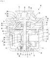
FIG. 1 is a sectional view showing an example motor. -
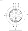
FIG. 2 is an exploded perspective view showing the example motor. -
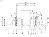
FIG. 3 is an enlarged sectional view of portion A ofFIG. 1 . -
FIG. 4 is a cross-sectional view showing an example elastic mesh that has been elastically deformed by an example bearing. -
FIG. 5 is an example lifespan graph of example bearings with respect to their concentricity error. -
FIG. 6 is a sectional view showing another example elastic mesh. -
FIG. 7 is a sectional view showing another example elastic mesh. -
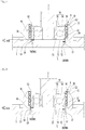
FIG. 8 is an enlarged sectional view showing example main parts of another example motor. -
FIG. 9 is an enlarged sectional view showing example main parts of another example motor. -
FIG. 10 is an enlarged sectional view showing example main parts of another example motor. -
FIG. 11 is an enlarged sectional view showing main example parts of another example motor. - Hereinafter, exemplary implementations of the present disclosure will be described in detail with reference to the accompanying drawings.
-
FIG. 1 is a sectional view showing a first example motor.FIG. 2 is an exploded perspective view showing the motor.FIG. 3 is an enlarged sectional view of portion A ofFIG. 1 .FIG. 4 is a cross-sectional view showing an example elastic mesh that is elastically deformed by an example bearing in the first example motor. - The motor M of this implementation includes, for example, a
motor housing 1, a rotating shaft assembly R, and astator 2. - The
motor housing 1 may form an external appearance of the motor M. Themotor housing 1 may have a hollow cylindrical shape having one open surface. Anair outlet 11 through which air inside themotor housing 1 is discharged to the outside may be formed in themotor housing 1. A plurality ofair outlets 11 may be formed in themotor housing 1. - The rotating shaft assembly R includes a
rotating shaft 3 and a rotor 4 mounted to therotating shaft 3. - The
stator 2 may be installed in themotor housing 1 to surround the rotor 4. Thestator 2 may be mounted to themotor housing 1 using a fastening member such as a screw. Thestator 2 may be formed in a hollow cylindrical shape, and may surround the outer circumference of the rotor 4. - The
stator 2 may be configured as an assembly of a plurality of members. Thestator 2 may include astator core 21, a pair ofinsulators stator core 21, and acoil 24 disposed at theinsulators - The
rotating shaft 3 is rotated together with the rotor 4, and may be supported by abearing 5. Therotating shaft 3 may be rotated by the rotor 4. - A portion of the
rotating shaft 3 may be located inside themotor housing 1, and the rest of therotating shaft 3 may be located inside animpeller cover 73 which will be described later. Therotating shaft 3 may be disposed long from the inside of themotor housing 1 to the inside of theimpeller cover 73. - In some implementations, an
impeller connection part 32 to which animpeller 71 is connected may be formed at therotating shaft 3. Theimpeller connection part 32 may be formed at a position spaced apart from apart 31 surrounded by the rotor 4. Theimpeller connection part 32 may be formed at an end portion of therotating shaft 3. - A bearing mounting part at which the
bearing 5 is mounted may be formed at therotating shaft 3. In some implementations, a second bearing mounting part at which a second bearing 6 which will be described later is mounted may be formed at therotating shaft 3. - The rotor 4 may be mounted to surround a portion of the
rotating shaft 3. The rotor 4 may be rotatably located inside thestator 2. The rotor 4 may be formed in a hollow cylindrical shape. - The rotor 4 may include an
iron core 41 fixed to therotating shaft 3, amagnet 42 installed at theiron core 41, and a pair ofend plates magnet 42. - The rotor 4 may be mounted to surround the
part 31 between one end and the other end of therotating shaft 3. The rotor 4 may be mounted between theimpeller connection part 32 and the bearing mounting part. - The motor M includes the
bearing 5 mounted to therotating shaft 3, and anelastic mesh 9 disposed between themotor housing 1 and thebearing 5, theelastic mesh 9 having a plurality of pores S2 and S3 formed therein. - In some implementations, the motor M may further include the
impeller 71 connected to therotating shaft 3, and theimpeller cover 73 surrounding the outer circumference of theimpeller 71, theimpeller cover 73 having anair inlet 72 formed therein. - The
bearing 5 may include aninner rim 51 fixed to therotating shaft 3, anouter rim 52 spaced apart from theinner rim 51, and a rollingmember 53 disposed between theinner rim 51 and theouter rim 52. - The
bearing 5 may be one of a roller bearing and a ball bearing. Thebearing 5 is preferably configured as a ball bearing in which the rollingmember 53 is configured as a ball to have high performance in high-speed rotation. - In some implementations, the
bearing 5 may be mounted to therotating shaft 3 to be located inside themotor housing 1. An examplehollow part 12 larger than thebearing 5 may be formed in themotor housing 1. Thehollow part 12 may be formed larger than thebearing 5. A gap in which at least a portion of theelastic mesh 9 is inserted and accommodated may be formed between thehollow part 12 and thebearing 5. Thebearing 5 and theelastic mesh 9 may be accommodated together in thehollow part 12. - As shown in
FIG. 3 , the internal diameter D2 of thehollow part 12 may be formed greater than the external diameter D1 of thebearing 5, and at least a portion of theelastic mesh 9 may be disposed between the inner circumferential surface of thehollow part 12 and the outer circumferential surface of thebearing 5. The internal diameter D2 of thehollow part 12 may be greater than the external diameter D1 of theouter rim 52 of thebearing 5, and theelastic mesh 9 may be disposed between theouter rim 52 of thebearing 5 and thehollow part 12. - The
motor housing 1, as shown inFIG. 4 , may include thehollow part 12 and anexample body part 13. Thehollow part 12 may protrude from thebody part 13 and surround the outer circumference of theelastic mesh 9. Thehollow part 12 may protrude toward the rotor 4 shown inFIG. 1 from thebody part 13. - At least one through-
hole 14 facing theelastic mesh 9 may be formed in thebody part 13. - A plurality of through-
holes 14 may be formed in thebody part 13. The plurality of through-holes 14 may be formed in thebody part 13 to be spaced apart from one another in the circumferential direction. The plurality of through-holes 14 may face a partial area of theelastic mesh 9. - A flow path through which air passes may be formed between the
hollow part 12 and thebearing 5, and the air may be guided to the flow path between thehollow part 12 and thebearing 5 by the through-hole 14 formed in thebody part 13. Theelastic mesh 9 may be disposed in the flow path formed between thehollow part 12 and thebearing 5, and heat transferred from thebearing 5 can be efficiently dissipated by theelastic mesh 9. - The motor M may further include an O-
ring 54 fixed to therotating shaft 3, the O-ring 54 supportingbearing 5. - The O-
ring 54 may be fixed to therotating shaft 3, and may constitute a rotating shaft assembly (or rotor assembly) together with therotating shaft 3 and the rotor 4. - The O-
ring 54 may be located between thebearing 5 and the rotor 4 in the length direction of therotating shaft 3. The O-ring 54 may restrict thebearing 5 from moving toward the rotor 4. The O-ring 54 may serve as a bearing stopper supporting thebearing 5. - The O-
ring 54 may be fixed to therotating shaft 3 to come in contact with a portion of thebearing 5. At least one portion of the O-ring 54 may face theinner rim 51 of thebearing 5. The O-ring 54 may come in contact with theinner rim 51 of thebearing 5. The O-ring 54 may be a bearing stopper that restricts theinner rim 51 of thebearing 5 from sliding toward the rotor 4. - As shown in
FIG. 4 , the external diameter D3 of the O-ring 54 may be smaller than the internal diameter D4 of theelastic mesh 9. The O-ring 54 may be located inside theelastic mesh 9. When therotating shaft 3 rotates, the O-ring 54 may be rotated in a space formed inside theelastic mesh 9. - A gap G1 may be formed between the outer circumference of the O-
ring 54 and theelastic mesh 9, and the O-ring 54 and theelastic mesh 9 do not come in contact with each other due to the gap G1. - Abrasion of the O-
ring 54 or theelastic mesh 9, which occurs when the O-ring 54 and theelastic mesh 9 comes in contact with each other, can be minimized due to the gap G1. For example, the lifespan of each of the O-ring 54 and theelastic mesh 9 can be maximized due to the gap G1 formed between the outer circumference of the O-ring 54 and theelastic mesh 9. - In some implementations, the gap G1 between the outer circumference of the O-
ring 54 and theelastic mesh 9 may form a flow path through which the air inside the motor M may flow into thebearing 5 and theelastic mesh 9. The air inside the motor M may flow into thebearing 5 and theelastic mesh 9 through the gap G1 between the outer circumference of the O-ring 54 and theelastic mesh 9, to dissipate heat of each of thebearing 5 and theelastic mesh 9. - The O-
ring 54 may be mounted to therotating shaft 3 to come in contact with theinner rim 51 of thebearing 5. The O-ring 54 may be spaced apart from each of theouter rim 52 of thebearing 5 and theelastic mesh 9. - The O-
ring 54 may include aninner ring 55 coming in contact with theinner rim 51 and anouter ring 56 spaced apart from theouter rim 52. - The outer circumference of the
outer ring 56 may be the outer circumference of the O-ring 54, and the external diameter of theouter ring 56 may be the external diameter of the O-ring 54. - In some implementations, the
body part 13 of themotor housing 1 may be spaced apart from the O-ring 54, and a bearing accommodation space S1 in which thebearing 5 is accommodated may be formed between the O-ring 54 and thebody part 13. - The
impeller 71 may be rotated together with therotating shaft 3 in the state in which theimpeller 71 is connected to therotating shaft 3. Theimpeller 71 may be located between theimpeller cover 73 and adiffuser 74 which will be described later. - The
impeller cover 73 may protect theimpeller 71 by surrounding the outer circumference of theimpeller 71. - A surface of the
impeller cover 73, which is opposite to themotor housing 1, may be open. Theimpeller cover 73 may be disposed to cover an open surface of themotor housing 1. Theimpeller cover 73 may be coupled to themotor housing 1 or abracket 8 using a fastening member such as a screw, or may be screw-coupled to themotor housing 1 or thebracket 8. - The
air inlet 72 may be formed smaller than the surface of theimpeller cover 73, which is opposite to themotor housing 1. - The inner circumferential surface of the
impeller cover 73 may be spaced apart from theimpeller 71, and air moved by theimpeller 71 may flow between the inner circumferential surface of theimpeller cover 73 and theimpeller 71. - In some implementations, the motor M may further include the
diffuser 74 located inside theimpeller cover 73. Thediffuser 74 may be mounted to at least one of theimpeller cover 73 and thebracket 8. - The
diffuser 74 may include abody part 75 having a smaller size than theimpeller cover 73, adiffuser vane 76 protruding from the outer circumference of thebody part 75, and a guide vane 77 guiding air flowed by thediffuser vane 76 to thestator 2 and the rotor 4. - The
diffuser vane 76 may be formed to transform the dynamic pressure of air passing through theimpeller 71 to static pressure. - The guide vane 77 may guide air of which pressure is increased by the
diffuser vane 76 to thestator 2 and the rotor 4. - In some implementations, the
rotating shaft 3 may be directly supported by thebracket 8 which will be described later. When therotating shaft 3 is directly supported by thebracket 8, a rotating shaft support part rotatably supporting therotating shaft 3 may be formed at thebracket 8. The rotating shaft support part may be formed at thebracket 8 to surround the outer circumference of therotating shaft 3. A lubrication medium for preventing abrasion between therotating shaft 3 and the rotating shaft support part, such as a lubricant, may be provided to at least one of therotating shaft 3 and the rotating shaft support part. - The
rotating shaft 3 may be supported bybracket 8 through the second bearing 6. The second bearing 6 may be mounted torotating shaft 3. The second bearing 6 may rotatably support therotating shaft 3 between therotating shaft 3 and thebracket 8. - The second bearing 6 may be mounted to the
rotating shaft 3 to be spaced apart from thebearing 5. The second bearing 6 may be spaced apart from thebearing 5 in the length direction of therotating shaft 3. - The
bearing 5 and the second bearing 6 may rotatably support therotating shaft 3 at positions spaced apart from each other. In this case, the weight of therotating shaft 3 may be distributed by thebearing 5 and the second bearing 6. - The
bearing 5 and the second bearing 6 may be mounted to be spaced apart from each other with the rotor 4 interposed therebetween. As another example, thebearing 5 and the second bearing 6 may be mounted to be located together between the rotor 4 and theimpeller 71. - The
bearing 5 may be located between therotating shaft 3 and themotor housing 1 to support therotating shaft 3. In some implementations, the second bearing 6 may be located between therotating shaft 3 and thebracket 8 to support therotating shaft 3. In this case, thebearing 5 may be spaced apart from the second bearing 6 with the rotor 4 interposed therebetween. - When the motor M includes both of the
bearing 5 and the second bearing 6, thebearing 5 may be a load-side bearing close to theimpeller 71, and the second bearing 6 may be a non-load-side bearing distant from theimpeller 71. In some implementations, thebearing 5 may be a motor housing-side bearing surrounded bymotor housing 1, and the second bearing 6 may be a bracket-side bearing surrounded by thebracket 8. - The
bearing 5 may be an end bearing or first bearing mounted at an end portion of therotating shaft 3, which is opposite to theimpeller 71. In some implementations, the second bearing 6 may be a bearing mounted between theimpeller 71 and thebearing 5, for example, between theimpeller 71 and the rotor 4. - When the second bearing 6 is directly supported by the
bracket 8, the outer circumferential surface of the second bearing 6 may come in contact with thebracket 8 to be supported by thebracket 8. - The second bearing 6 may include an
inner rim 61 fixed to therotating shaft 3, anouter rim 62 spaced apart from theinner rim 61, and a rolling member 63 disposed between theinner rim 61 and theouter rim 62. - The second bearing 6 may be one of a roller bearing and a ball bearing. The second bearing 6 is preferably configured as a ball bearing in which the rolling member 63 is configured as a ball to have high performance in high-speed rotation.
- The
inner rim 61 of the second bearing 6 may be fixed to therotating shaft 3, and theouter rim 62 of the second bearing 6 may come in contact with thebracket 8 to be fixed to thebracket 8. - The motor M may further include a second O-
ring 64 fixed to therotating shaft 3, the second O-ring 64 supporting the second bearing 6. The second O-ring 64 may be fixed to therotating shaft 3, and may constitute a rotating shaft assembly (or rotor assembly) together with therotating shaft 3 and the rotor 4. - The second O-
ring 64 may be located between the rotor 4 and the second bearing 6 in the length direction of therotating shaft 3. The second O-ring 64 may restrict the second bearing 6 from moving toward the rotor 4. The second O-ring 64 may serve as a bearing stopper supporting the second bearing 6. - The second O-
ring 64 may be fixed to therotating shaft 3 to come in contact with a portion of the second bearing 6. At least one portion of the second O-ring 64 may face theinner rim 61 of the second bearing 6. The second O-ring 64 may come in contact with theinner rim 61 of the second bearing 6. The second O-ring 64 may be a bearing stopper that restricts theinner rim 61 of the second bearing 6 from sliding toward the rotor 4. - The second O-
ring 64 may be mounted to therotating shaft 3, come in contact with theinner rim 61 of the second bearing 6, and be spaced apart from a bearinghousing part 81 which will be described later. - In some implementations, the
bracket 8 may be mounted in at least one of themotor housing 1 and theimpeller cover 73. - The
bracket 8 may include the bearinghousing part 81 coming in contact with theouter rim 62 of the second bearing 6 to be supported by theouter rim 62 of the second bearing 6, the bearinghousing part 81 accommodating the second bearing 6 therein. - The bearing
housing part 81 may include a hollow cylindrical part of which inner circumferential surface comes in contact with theouter rim 62 of the second bearing 6, and a ring part having a smaller internal diameter than the hollow cylindrical part, the ring part covering between theinner rim 61 of the second bearing 6 and theouter rim 62 of the second bearing 6. - The bearing
housing part 81 may be formed larger than the second O-ring 64, and the internal diameter of the bearinghousing part 81 of thebracket 8 may be greater than the external diameter of the second O-ring 64. The second O-ring 64 may be rotated in a space formed inside the bearinghousing part 81. - A rotating shaft through-
hole 83 through which therotating shaft 3 rotatably passes may be formed in the bearinghousing part 81. - The
bracket 8 may include afastening part 84 fastened to at least one of themotor housing 1 and theimpeller cover 73. Thefastening part 84 may be formed in a ring shape. Thefastening part 84 may be fastened to at least one of themotor housing 1 and theimpeller cover 73 using afastening member 85 such as a screw. Thefastening part 84 may be formed larger than the bearinghousing part 81. Thebracket 8 may include at least oneconnection part 86 connecting thefastening part 84 and the bearinghousing part 81. - The
bearing 5 and the second bearing 6 are preferably mounted such that their center axes correspond to each other. When the center axes of thebearing 5 and the second bearing 6 do not correspond to each other, the abrasion of any one of thebearing 5 and the second bearing 6 may be large. - In the motor M, the center axis of the bearing
housing part 81 and the center axis H1 of thehollow part 12 may not correspond to each other due to an assembly tolerance of themotor housing 1 and thebracket 8. - Although the center axis of the bearing
housing part 81 and the center axis H1 of thehollow part 12 do not correspond to each other, theelastic mesh 9 of this implementation may adjust the position of thebearing 5 to be aligned with the position of the second bearing 6 such that the center axis B1 of thebearing 5 and the center axis of the second bearing 6 correspond to each other. - The
elastic mesh 9 may be disposed between thehollow part 12 and thebearing 5, and may elastically support thebearing 5. Theelastic mesh 9 may be press-fitted between thebearing 5 and thehollow part 12. - In the motor M, the concentricities of the
bearing 5 and the second bearing 6 may not correspond to each other due to the assembly tolerance of themotor housing 1 and thebracket 8. When the concentricities of thebearing 5 and the second bearing 6 do not correspond to each other, theelastic mesh 9 may support thebearing 5 such that the concentricities of thebearing 5 and the second bearing 6 correspond to each other in a state in which a portion of theelastic mesh 9 is elastically compressed by thebearing 5. - For example, the
bearing 5, as shown inFIG. 3 , may pressurize a portion of theelastic mesh 9 in the state in which thecenter axis B 1 of thebearing 5 does not correspond to the center axis H1 of thehollow part 12. In this case, theelastic mesh 9 may support thebearing 5 in the state in which the portion pressurized by thebearing 5 is compressed. - The
elastic mesh 9 is preferably formed in a structure in which theelastic mesh 9 is easily elastically deformed, and heat transferred from thebearing 5 is easily dissipated. - The plurality of pores S2 and S3 may be formed in the
elastic mesh 9. Theelastic mesh 9 may be disposed between thehollow part 12 and thebearing 5 to come in contact with at least one of thehollow part 12 and thebearing 5. - The
elastic mesh 9 may have a hollow cylindrical shape. A cylindrical empty space may be formed inside theelastic mesh 9. - At least a portion of the
elastic mesh 9 may be disposed between the outer circumference of theouter rim 52 of thebearing 5 and the inner circumference of thehollow part 12. Theelastic mesh 9 may come in contact with each of theouter rim 52 and thehollow part 12. - The height L1 of the
elastic mesh 9 may be greater than the height L2 of thebearing 5. A portion of theelastic mesh 9 may be disposed between theouter rim 52 of thebearing 5 and thehollow part 12. The internal diameter of theelastic mesh 9 may be equal to or smaller than the external diameter of theouter rim 52 of thebearing 5. In some implementations, the external diameter of theelastic mesh 9 may be equal to or greater than the internal diameter of thehollow part 12. - A portion of the
elastic mesh 9 may be press-fitted between theouter rim 52 of thebearing 5 and thehollow part 12, and may be fixed between theouter rim 52 of thebearing 5 and thehollow part 12 in the state in which the portion of theelastic mesh 9 is press-fitted. In some implementations, the internal diameter D4 of theelastic mesh 9 may be greater than the external diameter D3 of theouter ring 56 of the O-ring 54. - The
elastic mesh 9 may include afirst area 9A that faces thebearing 5 and a second area 9B that does not face thebearing 5. - The
first area 9A of theelastic mesh 9 may face the bearing accommodation space S1. The second area 9B of theelastic mesh 9 may include an area that faces the O-ring 54. The second area 9B of theelastic mesh 9 may further include an area that does not face both of the bearing accommodation space S1 and the O-ring 54. - The
elastic mesh 9 may have oneend 94 mounted on thebody part 13. The oneend 94 of theelastic mesh 9 may come in contact with thebody part 13. When the oneend 94 of theelastic mesh 9 comes in contact with thebody part 13, the oneend 94 of theelastic mesh 9 may be held by thebody part 13, and the mounting position of theelastic mesh 9 may be determined by thebody part 13. - In some implementations, the
elastic mesh 9 may be protected by theouter rim 52 of thebearing 5, thehollow part 12, and thebody part 13. - In some implementations, the
elastic mesh 9 may have theother end 95 spaced apart from the rotor 4, theother end 95 facing the rotor 4. The other end of theelastic mesh 9 may be located at the outside of the bearing accommodation space S1. - The
elastic mesh 9 may include a metal wire mesh. At least onemetal wire 91 of theelastic mesh 9 may be regularly or irregularly tangled. For example, themetal wire 91 may have a shape that includes a plurality of curved sections such as a curled shape, a twisted shape, a wound shape, and a spiral shape, or the like. - Heat of the
bearing 5 may be transferred to themetal wire 91, and the heat transferred to themetal wire 91 may be transferred to thehollow part 12 through a hollowpart contact part 92 of themetal wire 91, which comes in contact with thehollow part 12. - In some implementations, the heat transferred to the
metal wire 91 may be dissipated in an air cooling manner through the second area 9B of themetal wire 91, which does not face thebearing 5. - For example, the heat of the
bearing 5 may be transferred to themotor housing 1 through theelastic mesh 9, and the heat transferred to themotor housing 1 may be transferred to air in the motor M through theelastic mesh 9. - The plurality of pores S2 and S3 may be open in the radial direction of the
elastic mesh 9. The plurality of pores S2 and S3 may include at least one first pore S2 that faces theouter rim 52 of thebearing 5 and at least one second pore S3 that does not face theouter rim 52 of thebearing 5. - The second pore S3 may be located at the outside of the bearing accommodation space S1, and the air inside the motor M may be introduced into the
elastic mesh 9 through the second pore S3. - Hereinafter, heat dissipation of the bearing according to this implementation will be described in detail as follows.
- In the motor M, when the
rotating shaft 3 rotates, theimpeller 71 may be rotated, and air may be sucked into theimpeller 71 through theair inlet 72. - The air sucked into the
impeller 71 may flow into thediffuser 74, and the air flowing into thediffuser 74 may be sequentially guided by thediffuser vane 76 and the guide vane 77. - The air guided by the guide vane 77 may flow into the
stator 2 and the rotor 4, and may dissipate heat of thestator 2 and the rotor 4 in the air cooling manner inside the motor M. - A portion of the air inside the motor M may be introduced into the bearing accommodation space S1 through the gap G1 between the O-
ring 54 and theelastic mesh 9, and the air introduced into the bearing accommodating space S1 may be introduced between theouter rim 52 of thebearing 5 and thehollow part 12 through the plurality of pores S2 and S3 formed in theelastic mesh 9. - At least a portion of the air may pass between the
outer rim 52 of thebearing 5 and thehollow part 12 through the plurality of pores S2 and S3 formed in theelastic mesh 9, come in contact with each of thebearing 5, theelastic mesh 9, and thehollow part 12 between the outer circumferential surface of the bearing and thehollow part 12, and absorb heat of each of thebearing 5, theelastic mesh 9, and thehollow part 12. - The air dissipating the heat of the
bearing 5, theelastic mesh 9, and thehollow part 12 may be discharged to the outside of themotor housing 1 through the through-hole 14 facing theelastic mesh 9. -
FIG. 5 is an example graph of lifespan of example bearings with respect to their concentricity error. - For instance,
FIG. 5 is an example graph showing lifespan of each bearing with respect to its concentricity error between thebearing 5 and the second bearing 6, shown inFIG. 1 . When the concentricity error between thebearing 5 and the second bearing 6 is, for example, 0.05 mm or less, the lifespan of each bearing can be highly maintained. When the concentricity error between thebearing 5 and the second bearing 6 is 0.05 mm or more, the lifespan of each bearing may be rapidly decreased as shown inFIG. 5 . - In this example, the concentricity error between the
bearing 5 and the second bearing 6 of this implementation may be maintained to be 0.05 mm or less for a longer lifespan. In this implementation, although the center axis of thebearing 5 and the center axis of the second bearing 6 may not align to each other, theelastic mesh 9 elastically deformed by thebearing 5 may maintain the center axis of thebearing 5 and the center axis of the second bearing 6 to have an error of 0.05 mm or less, and thus the lifespan of each of thebearing 5 and the second bearing 6 can be maximized. -
FIG. 6 is a sectional view showing another example of the elastic mesh shown inFIG. 4 . - The motor M of this implementation may include an example thermal conductive adhesive 96 that fixes the
elastic mesh 9 to at least one of the outer circumferential surface of thebearing 5 and thehollow part 12. - The thermal conductive adhesive 96 may be located between the
outer rim 52 of thebearing 5 and thehollow part 12. - The thermal conductive adhesive 96 may restrict the
elastic mesh 9 from being arbitrarily separated between theouter rim 52 of thebearing 5 and thehollow part 12. - The thermal conductive adhesive 96 may be formed at a plurality of portions between the
outer rim 52 of thebearing 5 and thehollow part 12. - Air introduced into the
elastic mesh 9 may be diffused into theelastic mesh 9 while passing between the thermalconductive adhesives 96. -
FIG. 7 is a sectional view showing still another example of the elastic mesh shown inFIG. 4 . - An example elastic mesh 9' of this implementation may have a shape in which a mesh part having a plurality of pores formed therein is curled at least twice.
- The elastic mesh 9' may be manufactured by curling, plural times, a strip-shaped mesh part in a scroll form. The strip-shaped mesh part may be formed of a metal having a high heat transfer performance. The strip-shaped mesh part may be configured such that a plurality of metal wires are irregularly coupled, or may be configured such that a plurality of metal wires are arranged in a regular pattern such as a grid pattern.
- In the elastic mesh 9', an
inner mesh part 97 located at the innermost side in the radial direction may come in contact with the outer circumferential surface of thebearing 5. In some implementations, anouter mesh part 99 located at the outermost side in the radial direction may come in contact with thehollow part 12. At least a portion of theouter mesh part 99 may come in contact with the inner circumferential surface of thehollow part 12. - In some implementations, the elastic mesh 9' may further include at least one center mesh part 98 located between the
inner mesh part 97 and theouter mesh part 99. The center mesh part 98 may be curled to surround theinner mesh part 97, and theouter mesh part 99 may be curled to surround the center mesh part 98. - The elastic mesh 9' of this implementation may include the
inner mesh part 97 and theouter mesh part 99 without the center mesh part 98. In this case, theouter mesh part 99 may be curled to surround theinner mesh part 97. - In this implementation, the elastic mesh 9' formed in a hollow cylindrical shape can be manufactured through a simple process of curling, plural times, one strip-shaped mesh part in a scroll form. In addition, heat can be dissipated through not only the pores formed in the mesh part but also pores between the
mesh parts -
FIG. 8 is an enlarged sectional view showing main parts of another example motor. - The motor of this implementation may include a
wave washer 58 disposed between anouter rim 52 of abearing 5 and abody part 13. In addition, a mountingprojection 16 on which anelastic mesh 9 is mounted to be spaced apart from thewave washer 58 may protrude from thebody part 13. - The other components except the
wave washer 58 and the mountingprojection 16 are identical to those of the first implementation described above. Therefore, those components are designated by like reference numerals, and their detailed descriptions will be omitted. - The
wave washer 58 may be formed in a ring shape, for instance. Thewave washer 58 may include aconvex part 58A formed convex toward theouter rim 52 of thebearing 5 to come in contact with theouter rim 52 of thebearing 5, and aconcave part 58B recessed in a direction distant from theouter rim 52 of thebearing 5 to be spaced apart from theouter rim 52 of thebearing 5. Theconvex part 58A and theconcave part 58B may be alternately formed in the circumferential direction of thewave washer 58. - The
wave washer 58 may be disposed between theouter rim 52 of thebearing 5 and thebody part 13 such that theconvex part 58A can come in contact with theouter rim 52 of thebearing 5. - When the
outer rim 52 of thebearing 5 is vibrated, thewave washer 58 is elastically deformed between theouter rim 52 of thebearing 5 and thebody part 13, to buffer and absorb vibration transferred to theouter rim 52 of thebearing 5 and to minimize noise of thebearing 5. - In some implementations, the
body part 13 may include a wavewasher mounting surface 17 on which thewave washer 58 is mounted. The wavewasher mounting surface 17 may be formed flat at a portion of thebody part 13, which is opposite to theouter rim 52 of thebearing 5. - In some implementations, the mounting
projection 16 may be formed to be stepped with the wavewasher mounting surface 17. The mountingprojection 16 may be formed higher than the wavewasher mounting surface 17. - The height H3 of the mounting
projection 16 may be greater than the height H4 of thewave washer 58. - One
end 94 of theelastic mesh 9 may be disposed to come in contact with the mountingprojection 16. When the oneend 94 of theelastic mesh 9 is mounted on the mountingprojection 16, theelastic mesh 9 may be held by the mountingprojection 16 such that the position of theelastic mesh 9 is determined. - A portion of a
metal wire 91 constituting theelastic mesh 9 may become loose as time elapses. When the mountingprojection 16 is not provided, the loose portion may be entered between theouter rim 52 of thebearing 5 and thewave washer 58. In this case, thewave washer 58 may be erroneously operated due to the portion of themetal wire 91, which is entered between theouter rim 52 of thebearing 5 and thewave washer 58. - In some implementations, a portion of the
elastic mesh 9, which is close to thewave washer 58, may be bent toward thewave washer 58 in the state in which theelastic mesh 9 maintains the hollow cylindrical shape. When the mountingprojection 16 is not provided, the bent portion may be entered between theouter rim 52 of thebearing 5 and thewave washer 58. In this case, thewave washer 58 may be erroneously operated due to the portion of theelastic mesh 9, which is entered between theouter rim 52 of thebearing 5 and thewave washer 58. - In some implementations, when the mounting
projection 16 is provided to amotor housing 1, and theelastic mesh 9 is mounted on the mountingprojection 16, the loose portion of themetal wire 91 or the bent portion of theelastic mesh 9 is blocked by the mountingprojection 16, not to be entered between theouter rim 52 of thebearing 5 and thewave washer 58. - In this implementation, the reliability of the
wave washer 58 can be improved as compared with when the mountingprojection 16 is not provided, and the erroneous operation of thewave washer 58 can be minimized. - The mounting
projection 16 may be formed larger than thewave washer 58. When thewave washer 58 is mounted on the wavewasher mounting surface 17, the mountingprojection 16 may surround the outer circumference of thewave washer 58. - The mounting
projection 16 may include aside surface 18 facing the outer circumferential surface of thewave washer 58. Theside surface 18 of the mountingprojection 16 may be formed in a circular shape, and thewave washer 58 may be disposed to be surrounded by theside surface 18 of the mountingprojection 16. - In some implementations, the diameter of the
side surface 18 of the mountingprojection 16 may be formed to be equal to or slightly greater than the external diameter of thewave washer 58. - When the position of the
wave washer 58 is moved, the outer circumference of thewave washer 58 may be held by theside surface 18 of the mountingprojection 16. Thus, the movement of the position of thewave washer 58 can be minimized, and thewave washer 58 can reduce vibration of theouter rim 52 of thebearing 5 with high reliability. -
FIG. 9 is an enlarged sectional view showing example main parts of another example motor. - In this implementation, at least one through-hole 14' may be formed in a
body part 13. The through-hole 14' may be formed to pass through a mountingprojection 16. The other components except the through-hole 14' are identical to those of the other implementations described above. Therefore, those components are designated by like reference numerals, and their detailed descriptions will be omitted. - The through-hole 14' may be formed from the outer surface of the
body part 13, which faces the outside of amotor housing 1, to the inner surface of the mountingprojection 16, which faces the inside of themotor housing 1. - The through-hole 14' may be formed at a portion except a
side surface 18 of the mountingprojection 16, and anelastic mesh 9 does not come in contact with awave washer 58 through the through-hole 14'. -
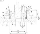
FIG. 10 is an enlarged sectional view showing example main parts of another example motor. - An example
elastic mesh 9" may include a firstelastic mesh part 9C disposed between the inner circumference of ahollow part 12 and the outer circumference of anouter rim 52 of abearing 5, and a secondelastic mesh part 9D bent from the firstelastic mesh part 9C, the secondelastic mesh part 9D being disposed between theouter rim 52 of thebearing 5 and abody part 13. The other components except theelastic mesh 9" are identical or similar to those of the other implementations described above. Therefore, those components are designated by like reference numerals, and their detailed descriptions will be omitted. - A second elastic mesh
part mounting surface 19 on which the secondelastic mesh part 9D is mounted may be formed at thebody part 13. - The first
elastic mesh part 9C may be formed in a hollow cylindrical shape. The firstelastic mesh part 9C may come in contact with an outercircumferential surface 52A of theouter rim 52 of thebearing 5. - The first
elastic mesh part 9C may be compressed/stretched in the radial direction by theouter rim 52 of thebearing 5. The firstelastic mesh part 9C may absorb vibration and impact applied to thebearing 5 in the radial direction. The firstelastic mesh part 9C may be elastically deformed by thebearing 5 to align the position of thebearing 5. - The second
elastic mesh part 9D may be formed in a ring shape. The internal diameter D5 of the secondelastic mesh part 9D may be formed smaller than the internal diameter D6 of the firstelastic mesh part 9C. The secondelastic mesh part 9D may come in contact with asurface 52B perpendicular to the outer circumferential surface of theouter rim 52 of thebearing 5. - The second
elastic mesh part 9D may be compressed/stretched in a direction parallel to arotating shaft 3 by theouter rim 52 of thebearing 5. The secondelastic mesh part 9D may assist the alignment of the position of thebearing 5 while absorbing vibration and impact applied to thebearing 5 in the height direction. - In this example, one
elastic mesh 9" can serve as each of theelastic mesh 9 and thewave washer 58, and may not include a separate structure such as the mountingprojection 16. In this implementation, it may be possible to decrease the number of parts and to simplify the structure. -
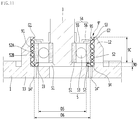
FIG. 11 is an enlarged sectional view showing example main parts of another example motor. - In this implementation, at least one through-
hole 14" may be formed in abody part 13. The through-hole 14" may be formed to face at least one of a firstelastic mesh part 9C and a secondelastic mesh part 9D. The other components except the through-hole 14" are identical or similar to those of the other implementations described above. Therefore, those components are designated by like reference numerals, and their detailed descriptions will be omitted. - The through-
hole 14" may be formed to have a position and a size, where the through-hole 14" faces each of the firstelastic mesh part 9C and the secondelastic mesh part 9D. - Air inside the motor M may pass through pores of each of the first
elastic mesh part 9C and the secondelastic mesh part 9D and be then discharged to the outside of the motor M through the through-hole 14". - Although some implementations of the present disclosure are described for illustrative purposes, it will be apparent to those skilled in the art that various modifications and changes can be made thereto within the scope of the disclosure without departing from the essential features of the disclosure.
- Accordingly, the aforementioned implementations are provided for illustrative purposes so that those skilled in the art can fully understand the concept of the present disclosure.
Claims (15)
- A motor (M) comprising:a motor housing (1);a rotating shaft (3)a bearing (5) mounted to the rotating shaft (3); andan elastic mesh (9) having a plurality of pores, the elastic mesh being disposed between the motor housing (1) and the bearing (3).
- The motor (M) according to claim 1, wherein the bearing (5) comprises:an inner rim (51) fixed to the rotating shaft (3);an outer rim (52) spaced apart from the inner rim (51); anda rolling member (53) disposed between the inner rim (51) and the outer rim (52),wherein the motor housing (1) includes a hollow part (12) that has an internal diameter (D2) greater than an external diameter (D1) of the outer rim (52) of the bearing (3), andwherein the elastic mesh (9) is disposed between the hollow part (12) and the outer rim (52) of the bearing (5).
- The motor according to claim 1, wherein the motor housing (1) comprises:a body part (13) that defines at least one through-hole (14) facing the elastic mesh (9); anda hollow part (12) that protrudes from the body part (13) and that surrounds an outer circumference of the elastic mesh (9).
- The motor (M) according to claim 1, wherein the motor housing (1) comprises:a body part (13); anda hollow part (12) that protrudes from the body part (13) and that surrounds an outer circumference of the elastic mesh (9),wherein the bearing (5) comprises:an inner rim (51) fixed to the rotating shaft (3),an outer rim (52) spaced apart from the inner rim (51), anda rolling member (53) disposed between the inner rim (51) and the outer rim (52), andwherein at least a portion of the elastic mesh (9) is disposed between an inner circumference of the hollow part (12) and an outer circumference of the outer rim (52).
- The motor (M) according to claim 4, further comprising a wave washer (58) that is disposed between the outer rim (52) and the body part (13) and spaced apart from the elastic mesh (9), wherein the body part (13) includes a mounting projection (16) that protrudes from the body part (13) and that seats the elastic mesh (9).
- The motor (M) according to claim 5, wherein the mounting projection (16) surrounds an outer circumference of the wave washer (58) and/or has a height greater (H3) than a height (H4) of the wave washer (58).
- The motor (M) according to claim 5 or 6, wherein the body part (13) includes a wave washer mounting surface (17) that seats the wave washer (58), and
wherein the mounting projection (16) is stepped from the wave washer mounting surface (17). - The motor (M) according to claim 4, wherein the elastic mesh (9") comprises:a first elastic mesh part (9C) disposed between the inner circumference of the hollow part (12) and the outer circumference of the outer rim (52); anda second elastic mesh part (9D) bent from the first elastic mesh part (9C) and disposed between the outer rim (52) and the body part (13).
- The motor (M) according to claim 8, wherein the body part (13) defines a through-hole (14") that faces at least one of the first elastic mesh part (9C) or the second elastic mesh part (9D).
- The motor (M) according to any one of claims 1 to 9, wherein the elastic mesh (9) comprises a metal wire mesh.
- The motor (M) according to any one of claims 1 to 10, wherein the elastic mesh (9) has a hollow cylindrical shape, and/or each pore of the plurality of pores has an opening in a radial direction of the elastic mesh (9), and/or wherein the elastic mesh (9) has a height greater than a height of the bearing (5).
- The motor (M) according to any one of claims 1 to 11, further comprising an O-ring (54) that is fixed to the rotating shaft (3), that is located between the elastic mesh (9) and the rotating shaft (3), and that supports the bearing (5),
wherein the O-ring (54) has an external diameter less than an internal diameter of the elastic mesh (9) to thereby define a gap between an outer circumference of the O-ring (54) and the elastic mesh (9). - The motor (M) according to any one of claims 1 to 12, wherein the elastic mesh (9) is configured to deform in a radial direction based on the rotating shaft (3) becoming offset from a center axis of the bearing (5) and/or the elastic mesh (9) is configured to communicate air through the through-hole and to discharge air to an outside of the motor housing (1).
- The motor (M) according to any one of claims 8 to 13, wherein the second elastic mesh part contacts both of the body part and the outer rim (52) of the bearing (5).
- The motor (M) according to any one of claims 8 to 14, wherein the second elastic mesh part defines a space between the body part and the inner rim (51) of the bearing (5) and is configured to deform in a direction parallel with the rotating shaft (3).
Applications Claiming Priority (5)
| Application Number | Priority Date | Filing Date | Title |
|---|---|---|---|
| KR1020160116747A KR101852114B1 (en) | 2016-09-09 | 2016-09-09 | Motor |
| KR1020160116746A KR101852835B1 (en) | 2016-09-09 | 2016-09-09 | Motor |
| KR1020160116431A KR101915846B1 (en) | 2016-09-09 | 2016-09-09 | Bearing and Motor having the same |
| KR1020160116748A KR101869159B1 (en) | 2016-09-09 | 2016-09-09 | Motor |
| KR1020160118058A KR101852111B1 (en) | 2016-09-13 | 2016-09-13 | Motor |
Publications (2)
| Publication Number | Publication Date |
|---|---|
| EP3293863A1 true EP3293863A1 (en) | 2018-03-14 |
| EP3293863B1 EP3293863B1 (en) | 2022-08-17 |
Family
ID=59829286
Family Applications (4)
| Application Number | Title | Priority Date | Filing Date |
|---|---|---|---|
| EP17190142.4A Active EP3293864B1 (en) | 2016-09-09 | 2017-09-08 | Rolling bearing and motor having the same |
| EP17190144.0A Active EP3293865B1 (en) | 2016-09-09 | 2017-09-08 | Motor |
| EP17190141.6A Active EP3293863B1 (en) | 2016-09-09 | 2017-09-08 | Motor |
| EP17190140.8A Active EP3293862B1 (en) | 2016-09-09 | 2017-09-08 | Motor |
Family Applications Before (2)
| Application Number | Title | Priority Date | Filing Date |
|---|---|---|---|
| EP17190142.4A Active EP3293864B1 (en) | 2016-09-09 | 2017-09-08 | Rolling bearing and motor having the same |
| EP17190144.0A Active EP3293865B1 (en) | 2016-09-09 | 2017-09-08 | Motor |
Family Applications After (1)
| Application Number | Title | Priority Date | Filing Date |
|---|---|---|---|
| EP17190140.8A Active EP3293862B1 (en) | 2016-09-09 | 2017-09-08 | Motor |
Country Status (1)
| Country | Link |
|---|---|
| EP (4) | EP3293864B1 (en) |
Families Citing this family (1)
| Publication number | Priority date | Publication date | Assignee | Title |
|---|---|---|---|---|
| GB2603463A (en) * | 2021-01-26 | 2022-08-10 | Donal Oflynn | Bearing Assembly for Wind Turbines |
Citations (5)
| Publication number | Priority date | Publication date | Assignee | Title |
|---|---|---|---|---|
| US4514458A (en) * | 1983-11-09 | 1985-04-30 | Lord Corporation | Spring-like material formed of compressed metallic wire |
| DE102005010459A1 (en) * | 2005-03-08 | 2006-09-14 | Vorwerk & Co. Interholding Gmbh | electric motor |
| DE102005025261A1 (en) * | 2005-06-02 | 2006-12-14 | Leybold Vacuum Gmbh | Vacuum pump has housing containing rolling bearing with stator ring and sprung heat bridging element located between housing and ring for rotory shaft thermally connecting the two for better heat conduction |
| US20070096572A1 (en) * | 2005-10-31 | 2007-05-03 | A. O. Smith Corporation | Slip fit tolerance ring |
| EP2899414A1 (en) * | 2014-01-23 | 2015-07-29 | Siemens Aktiengesellschaft | Damped bearing of a rotor shaft |
Family Cites Families (9)
| Publication number | Priority date | Publication date | Assignee | Title |
|---|---|---|---|---|
| US5059042A (en) * | 1990-01-02 | 1991-10-22 | Whirlpool Corporation | Bearing retainer for a vacuum cleaner motor |
| JP3891747B2 (en) * | 1999-12-07 | 2007-03-14 | 株式会社ジェイテクト | Electric steering device |
| US6848828B2 (en) * | 2002-03-08 | 2005-02-01 | Ntn Corporation | Foil bearing and spindle device using the same |
| DE102014200743A1 (en) * | 2014-01-16 | 2015-07-16 | Bosch Mahle Turbo Systems Gmbh & Co. Kg | turbocharger |
| KR102001911B1 (en) | 2015-03-31 | 2019-07-19 | 엘지전자 주식회사 | Vertical metal organic chemical vapor deposition apparatus for solar cell |
| KR101691435B1 (en) | 2015-03-30 | 2016-12-30 | 배재천 | Kintting yarn having retroreflectivity and retroreflective knitted fabric using the same |
| KR20160116748A (en) | 2015-03-31 | 2016-10-10 | 주식회사 샘코 | Wind direction auto directional VTOL drone and the method for controlling the same |
| KR20160116747A (en) | 2015-03-31 | 2016-10-10 | 엘지전자 주식회사 | Lighting device |
| KR102305652B1 (en) | 2015-04-01 | 2021-09-28 | 엘지이노텍 주식회사 | Motor |
-
2017
- 2017-09-08 EP EP17190142.4A patent/EP3293864B1/en active Active
- 2017-09-08 EP EP17190144.0A patent/EP3293865B1/en active Active
- 2017-09-08 EP EP17190141.6A patent/EP3293863B1/en active Active
- 2017-09-08 EP EP17190140.8A patent/EP3293862B1/en active Active
Patent Citations (5)
| Publication number | Priority date | Publication date | Assignee | Title |
|---|---|---|---|---|
| US4514458A (en) * | 1983-11-09 | 1985-04-30 | Lord Corporation | Spring-like material formed of compressed metallic wire |
| DE102005010459A1 (en) * | 2005-03-08 | 2006-09-14 | Vorwerk & Co. Interholding Gmbh | electric motor |
| DE102005025261A1 (en) * | 2005-06-02 | 2006-12-14 | Leybold Vacuum Gmbh | Vacuum pump has housing containing rolling bearing with stator ring and sprung heat bridging element located between housing and ring for rotory shaft thermally connecting the two for better heat conduction |
| US20070096572A1 (en) * | 2005-10-31 | 2007-05-03 | A. O. Smith Corporation | Slip fit tolerance ring |
| EP2899414A1 (en) * | 2014-01-23 | 2015-07-29 | Siemens Aktiengesellschaft | Damped bearing of a rotor shaft |
Also Published As
| Publication number | Publication date |
|---|---|
| EP3293863B1 (en) | 2022-08-17 |
| EP3293862B1 (en) | 2020-07-22 |
| EP3293865A1 (en) | 2018-03-14 |
| EP3293862A1 (en) | 2018-03-14 |
| EP3293865B1 (en) | 2022-11-02 |
| EP3293864B1 (en) | 2022-11-02 |
| EP3293864A1 (en) | 2018-03-14 |
Similar Documents
| Publication | Publication Date | Title |
|---|---|---|
| US10903714B2 (en) | Motor | |
| US20200373807A1 (en) | Motor including an elastic mesh supporting a bearing | |
| US10916990B2 (en) | Motor with bracket | |
| AU2021201908A1 (en) | Fan motor | |
| US10801547B2 (en) | Rolling bearing and motor having the same | |
| US11725669B2 (en) | Wind shroud and a fan with the same | |
| KR101915846B1 (en) | Bearing and Motor having the same | |
| EP3293863A1 (en) | Motor | |
| KR101869159B1 (en) | Motor | |
| WO2021227483A1 (en) | Rotary electric motor, and fan | |
| KR101922772B1 (en) | Motor | |
| JP6863477B2 (en) | Electric motor and electric blower | |
| EP3754817B1 (en) | Motor assembly and method for manufacturing the same | |
| KR102321267B1 (en) | Motor | |
| KR20200034486A (en) | Motor and Manufacturing method of the same | |
| EP3751712A1 (en) | Motor assembly and method for manufacturing the same | |
| KR102072179B1 (en) | Motor | |
| KR20200102816A (en) | Fan motor |
Legal Events
| Date | Code | Title | Description |
|---|---|---|---|
| PUAI | Public reference made under article 153(3) epc to a published international application that has entered the european phase |
Free format text: ORIGINAL CODE: 0009012 |
|
| STAA | Information on the status of an ep patent application or granted ep patent |
Free format text: STATUS: REQUEST FOR EXAMINATION WAS MADE |
|
| 17P | Request for examination filed |
Effective date: 20170908 |
|
| AK | Designated contracting states |
Kind code of ref document: A1 Designated state(s): AL AT BE BG CH CY CZ DE DK EE ES FI FR GB GR HR HU IE IS IT LI LT LU LV MC MK MT NL NO PL PT RO RS SE SI SK SM TR |
|
| AX | Request for extension of the european patent |
Extension state: BA ME |
|
| RBV | Designated contracting states (corrected) |
Designated state(s): AL AT BE BG CH CY CZ DE DK EE ES FI FR GB GR HR HU IE IS IT LI LT LU LV MC MK MT NL NO PL PT RO RS SE SI SK SM TR |
|
| R17P | Request for examination filed (corrected) |
Effective date: 20170908 |
|
| STAA | Information on the status of an ep patent application or granted ep patent |
Free format text: STATUS: EXAMINATION IS IN PROGRESS |
|
| STAA | Information on the status of an ep patent application or granted ep patent |
Free format text: STATUS: EXAMINATION IS IN PROGRESS |
|
| 17Q | First examination report despatched |
Effective date: 20210115 |
|
| STAA | Information on the status of an ep patent application or granted ep patent |
Free format text: STATUS: EXAMINATION IS IN PROGRESS |
|
| GRAP | Despatch of communication of intention to grant a patent |
Free format text: ORIGINAL CODE: EPIDOSNIGR1 |
|
| STAA | Information on the status of an ep patent application or granted ep patent |
Free format text: STATUS: GRANT OF PATENT IS INTENDED |
|
| INTG | Intention to grant announced |
Effective date: 20220316 |
|
| GRAS | Grant fee paid |
Free format text: ORIGINAL CODE: EPIDOSNIGR3 |
|
| GRAA | (expected) grant |
Free format text: ORIGINAL CODE: 0009210 |
|
| STAA | Information on the status of an ep patent application or granted ep patent |
Free format text: STATUS: THE PATENT HAS BEEN GRANTED |
|
| AK | Designated contracting states |
Kind code of ref document: B1 Designated state(s): AL AT BE BG CH CY CZ DE DK EE ES FI FR GB GR HR HU IE IS IT LI LT LU LV MC MK MT NL NO PL PT RO RS SE SI SK SM TR |
|
| REG | Reference to a national code |
Ref country code: CH Ref legal event code: EP |
|
| REG | Reference to a national code |
Ref country code: DE Ref legal event code: R096 Ref document number: 602017060686 Country of ref document: DE |
|
| REG | Reference to a national code |
Ref country code: IE Ref legal event code: FG4D |
|
| REG | Reference to a national code |
Ref country code: AT Ref legal event code: REF Ref document number: 1512812 Country of ref document: AT Kind code of ref document: T Effective date: 20220915 |
|
| REG | Reference to a national code |
Ref country code: NL Ref legal event code: MP Effective date: 20220817 |
|
| REG | Reference to a national code |
Ref country code: LT Ref legal event code: MG9D |
|
| PG25 | Lapsed in a contracting state [announced via postgrant information from national office to epo] |
Ref country code: SE Free format text: LAPSE BECAUSE OF FAILURE TO SUBMIT A TRANSLATION OF THE DESCRIPTION OR TO PAY THE FEE WITHIN THE PRESCRIBED TIME-LIMIT Effective date: 20220817 Ref country code: RS Free format text: LAPSE BECAUSE OF FAILURE TO SUBMIT A TRANSLATION OF THE DESCRIPTION OR TO PAY THE FEE WITHIN THE PRESCRIBED TIME-LIMIT Effective date: 20220817 Ref country code: PT Free format text: LAPSE BECAUSE OF FAILURE TO SUBMIT A TRANSLATION OF THE DESCRIPTION OR TO PAY THE FEE WITHIN THE PRESCRIBED TIME-LIMIT Effective date: 20221219 Ref country code: NO Free format text: LAPSE BECAUSE OF FAILURE TO SUBMIT A TRANSLATION OF THE DESCRIPTION OR TO PAY THE FEE WITHIN THE PRESCRIBED TIME-LIMIT Effective date: 20221117 Ref country code: NL Free format text: LAPSE BECAUSE OF FAILURE TO SUBMIT A TRANSLATION OF THE DESCRIPTION OR TO PAY THE FEE WITHIN THE PRESCRIBED TIME-LIMIT Effective date: 20220817 Ref country code: LV Free format text: LAPSE BECAUSE OF FAILURE TO SUBMIT A TRANSLATION OF THE DESCRIPTION OR TO PAY THE FEE WITHIN THE PRESCRIBED TIME-LIMIT Effective date: 20220817 Ref country code: LT Free format text: LAPSE BECAUSE OF FAILURE TO SUBMIT A TRANSLATION OF THE DESCRIPTION OR TO PAY THE FEE WITHIN THE PRESCRIBED TIME-LIMIT Effective date: 20220817 Ref country code: FI Free format text: LAPSE BECAUSE OF FAILURE TO SUBMIT A TRANSLATION OF THE DESCRIPTION OR TO PAY THE FEE WITHIN THE PRESCRIBED TIME-LIMIT Effective date: 20220817 Ref country code: ES Free format text: LAPSE BECAUSE OF FAILURE TO SUBMIT A TRANSLATION OF THE DESCRIPTION OR TO PAY THE FEE WITHIN THE PRESCRIBED TIME-LIMIT Effective date: 20220817 |
|
| PGFP | Annual fee paid to national office [announced via postgrant information from national office to epo] |
Ref country code: IT Payment date: 20221130 Year of fee payment: 6 |
|
| REG | Reference to a national code |
Ref country code: AT Ref legal event code: MK05 Ref document number: 1512812 Country of ref document: AT Kind code of ref document: T Effective date: 20220817 |
|
| PG25 | Lapsed in a contracting state [announced via postgrant information from national office to epo] |
Ref country code: PL Free format text: LAPSE BECAUSE OF FAILURE TO SUBMIT A TRANSLATION OF THE DESCRIPTION OR TO PAY THE FEE WITHIN THE PRESCRIBED TIME-LIMIT Effective date: 20220817 Ref country code: IS Free format text: LAPSE BECAUSE OF FAILURE TO SUBMIT A TRANSLATION OF THE DESCRIPTION OR TO PAY THE FEE WITHIN THE PRESCRIBED TIME-LIMIT Effective date: 20221217 Ref country code: HR Free format text: LAPSE BECAUSE OF FAILURE TO SUBMIT A TRANSLATION OF THE DESCRIPTION OR TO PAY THE FEE WITHIN THE PRESCRIBED TIME-LIMIT Effective date: 20220817 Ref country code: GR Free format text: LAPSE BECAUSE OF FAILURE TO SUBMIT A TRANSLATION OF THE DESCRIPTION OR TO PAY THE FEE WITHIN THE PRESCRIBED TIME-LIMIT Effective date: 20221118 |
|
| PG25 | Lapsed in a contracting state [announced via postgrant information from national office to epo] |
Ref country code: SM Free format text: LAPSE BECAUSE OF FAILURE TO SUBMIT A TRANSLATION OF THE DESCRIPTION OR TO PAY THE FEE WITHIN THE PRESCRIBED TIME-LIMIT Effective date: 20220817 Ref country code: RO Free format text: LAPSE BECAUSE OF FAILURE TO SUBMIT A TRANSLATION OF THE DESCRIPTION OR TO PAY THE FEE WITHIN THE PRESCRIBED TIME-LIMIT Effective date: 20220817 Ref country code: DK Free format text: LAPSE BECAUSE OF FAILURE TO SUBMIT A TRANSLATION OF THE DESCRIPTION OR TO PAY THE FEE WITHIN THE PRESCRIBED TIME-LIMIT Effective date: 20220817 Ref country code: CZ Free format text: LAPSE BECAUSE OF FAILURE TO SUBMIT A TRANSLATION OF THE DESCRIPTION OR TO PAY THE FEE WITHIN THE PRESCRIBED TIME-LIMIT Effective date: 20220817 Ref country code: AT Free format text: LAPSE BECAUSE OF FAILURE TO SUBMIT A TRANSLATION OF THE DESCRIPTION OR TO PAY THE FEE WITHIN THE PRESCRIBED TIME-LIMIT Effective date: 20220817 |
|
| REG | Reference to a national code |
Ref country code: CH Ref legal event code: PL |
|
| REG | Reference to a national code |
Ref country code: DE Ref legal event code: R097 Ref document number: 602017060686 Country of ref document: DE |
|
| REG | Reference to a national code |
Ref country code: BE Ref legal event code: MM Effective date: 20220930 |
|
| PG25 | Lapsed in a contracting state [announced via postgrant information from national office to epo] |
Ref country code: SK Free format text: LAPSE BECAUSE OF FAILURE TO SUBMIT A TRANSLATION OF THE DESCRIPTION OR TO PAY THE FEE WITHIN THE PRESCRIBED TIME-LIMIT Effective date: 20220817 Ref country code: MC Free format text: LAPSE BECAUSE OF FAILURE TO SUBMIT A TRANSLATION OF THE DESCRIPTION OR TO PAY THE FEE WITHIN THE PRESCRIBED TIME-LIMIT Effective date: 20220817 Ref country code: EE Free format text: LAPSE BECAUSE OF FAILURE TO SUBMIT A TRANSLATION OF THE DESCRIPTION OR TO PAY THE FEE WITHIN THE PRESCRIBED TIME-LIMIT Effective date: 20220817 |
|
| PLBE | No opposition filed within time limit |
Free format text: ORIGINAL CODE: 0009261 |
|
| STAA | Information on the status of an ep patent application or granted ep patent |
Free format text: STATUS: NO OPPOSITION FILED WITHIN TIME LIMIT |
|
| PG25 | Lapsed in a contracting state [announced via postgrant information from national office to epo] |
Ref country code: LU Free format text: LAPSE BECAUSE OF NON-PAYMENT OF DUE FEES Effective date: 20220908 Ref country code: AL Free format text: LAPSE BECAUSE OF FAILURE TO SUBMIT A TRANSLATION OF THE DESCRIPTION OR TO PAY THE FEE WITHIN THE PRESCRIBED TIME-LIMIT Effective date: 20220817 |
|
| 26N | No opposition filed |
Effective date: 20230519 |
|
| PG25 | Lapsed in a contracting state [announced via postgrant information from national office to epo] |
Ref country code: LI Free format text: LAPSE BECAUSE OF NON-PAYMENT OF DUE FEES Effective date: 20220930 Ref country code: IE Free format text: LAPSE BECAUSE OF NON-PAYMENT OF DUE FEES Effective date: 20220908 Ref country code: FR Free format text: LAPSE BECAUSE OF NON-PAYMENT OF DUE FEES Effective date: 20221017 Ref country code: CH Free format text: LAPSE BECAUSE OF NON-PAYMENT OF DUE FEES Effective date: 20220930 |
|
| PG25 | Lapsed in a contracting state [announced via postgrant information from national office to epo] |
Ref country code: SI Free format text: LAPSE BECAUSE OF FAILURE TO SUBMIT A TRANSLATION OF THE DESCRIPTION OR TO PAY THE FEE WITHIN THE PRESCRIBED TIME-LIMIT Effective date: 20220817 |
|
| PG25 | Lapsed in a contracting state [announced via postgrant information from national office to epo] |
Ref country code: BE Free format text: LAPSE BECAUSE OF NON-PAYMENT OF DUE FEES Effective date: 20220930 |
|
| PGFP | Annual fee paid to national office [announced via postgrant information from national office to epo] |
Ref country code: GB Payment date: 20230807 Year of fee payment: 7 |
|
| PGFP | Annual fee paid to national office [announced via postgrant information from national office to epo] |
Ref country code: DE Payment date: 20230807 Year of fee payment: 7 |
|
| PG25 | Lapsed in a contracting state [announced via postgrant information from national office to epo] |
Ref country code: HU Free format text: LAPSE BECAUSE OF FAILURE TO SUBMIT A TRANSLATION OF THE DESCRIPTION OR TO PAY THE FEE WITHIN THE PRESCRIBED TIME-LIMIT; INVALID AB INITIO Effective date: 20170908 |