EP3293862B1 - Motor - Google Patents
Motor Download PDFInfo
- Publication number
- EP3293862B1 EP3293862B1 EP17190140.8A EP17190140A EP3293862B1 EP 3293862 B1 EP3293862 B1 EP 3293862B1 EP 17190140 A EP17190140 A EP 17190140A EP 3293862 B1 EP3293862 B1 EP 3293862B1
- Authority
- EP
- European Patent Office
- Prior art keywords
- bearing
- bracket
- supporter
- rotating shaft
- motor
- Prior art date
- Legal status (The legal status is an assumption and is not a legal conclusion. Google has not performed a legal analysis and makes no representation as to the accuracy of the status listed.)
- Active
Links
- 230000017525 heat dissipation Effects 0.000 claims description 40
- 239000011148 porous material Substances 0.000 claims description 32
- 239000002184 metal Substances 0.000 claims description 14
- 229910052751 metal Inorganic materials 0.000 claims description 14
- 238000005096 rolling process Methods 0.000 claims description 12
- 238000005299 abrasion Methods 0.000 description 3
- 238000013016 damping Methods 0.000 description 3
- XEEYBQQBJWHFJM-UHFFFAOYSA-N Iron Chemical group [Fe] XEEYBQQBJWHFJM-UHFFFAOYSA-N 0.000 description 2
- 230000006835 compression Effects 0.000 description 2
- 238000007906 compression Methods 0.000 description 2
- 239000000428 dust Substances 0.000 description 2
- 239000012212 insulator Substances 0.000 description 2
- 239000000463 material Substances 0.000 description 2
- 238000000034 method Methods 0.000 description 2
- 230000004308 accommodation Effects 0.000 description 1
- 238000002485 combustion reaction Methods 0.000 description 1
- 238000001816 cooling Methods 0.000 description 1
- 230000001419 dependent effect Effects 0.000 description 1
- 238000009434 installation Methods 0.000 description 1
- 239000000314 lubricant Substances 0.000 description 1
- 238000005461 lubrication Methods 0.000 description 1
- 238000012986 modification Methods 0.000 description 1
- 230000004048 modification Effects 0.000 description 1
- 230000036316 preload Effects 0.000 description 1
- 229910001220 stainless steel Inorganic materials 0.000 description 1
- 239000010935 stainless steel Substances 0.000 description 1
- 230000003068 static effect Effects 0.000 description 1
Images


Classifications
-
- H—ELECTRICITY
- H02—GENERATION; CONVERSION OR DISTRIBUTION OF ELECTRIC POWER
- H02K—DYNAMO-ELECTRIC MACHINES
- H02K5/00—Casings; Enclosures; Supports
- H02K5/04—Casings or enclosures characterised by the shape, form or construction thereof
- H02K5/16—Means for supporting bearings, e.g. insulating supports or means for fitting bearings in the bearing-shields
-
- F—MECHANICAL ENGINEERING; LIGHTING; HEATING; WEAPONS; BLASTING
- F04—POSITIVE - DISPLACEMENT MACHINES FOR LIQUIDS; PUMPS FOR LIQUIDS OR ELASTIC FLUIDS
- F04D—NON-POSITIVE-DISPLACEMENT PUMPS
- F04D17/00—Radial-flow pumps, e.g. centrifugal pumps; Helico-centrifugal pumps
- F04D17/08—Centrifugal pumps
- F04D17/16—Centrifugal pumps for displacing without appreciable compression
-
- F—MECHANICAL ENGINEERING; LIGHTING; HEATING; WEAPONS; BLASTING
- F04—POSITIVE - DISPLACEMENT MACHINES FOR LIQUIDS; PUMPS FOR LIQUIDS OR ELASTIC FLUIDS
- F04D—NON-POSITIVE-DISPLACEMENT PUMPS
- F04D29/00—Details, component parts, or accessories
- F04D29/05—Shafts or bearings, or assemblies thereof, specially adapted for elastic fluid pumps
- F04D29/056—Bearings
- F04D29/059—Roller bearings
-
- F—MECHANICAL ENGINEERING; LIGHTING; HEATING; WEAPONS; BLASTING
- F04—POSITIVE - DISPLACEMENT MACHINES FOR LIQUIDS; PUMPS FOR LIQUIDS OR ELASTIC FLUIDS
- F04D—NON-POSITIVE-DISPLACEMENT PUMPS
- F04D29/00—Details, component parts, or accessories
- F04D29/58—Cooling; Heating; Diminishing heat transfer
- F04D29/582—Cooling; Heating; Diminishing heat transfer specially adapted for elastic fluid pumps
- F04D29/584—Cooling; Heating; Diminishing heat transfer specially adapted for elastic fluid pumps cooling or heating the machine
-
- F—MECHANICAL ENGINEERING; LIGHTING; HEATING; WEAPONS; BLASTING
- F04—POSITIVE - DISPLACEMENT MACHINES FOR LIQUIDS; PUMPS FOR LIQUIDS OR ELASTIC FLUIDS
- F04D—NON-POSITIVE-DISPLACEMENT PUMPS
- F04D29/00—Details, component parts, or accessories
- F04D29/66—Combating cavitation, whirls, noise, vibration or the like; Balancing
- F04D29/661—Combating cavitation, whirls, noise, vibration or the like; Balancing especially adapted for elastic fluid pumps
- F04D29/668—Combating cavitation, whirls, noise, vibration or the like; Balancing especially adapted for elastic fluid pumps damping or preventing mechanical vibrations
-
- F—MECHANICAL ENGINEERING; LIGHTING; HEATING; WEAPONS; BLASTING
- F16—ENGINEERING ELEMENTS AND UNITS; GENERAL MEASURES FOR PRODUCING AND MAINTAINING EFFECTIVE FUNCTIONING OF MACHINES OR INSTALLATIONS; THERMAL INSULATION IN GENERAL
- F16C—SHAFTS; FLEXIBLE SHAFTS; ELEMENTS OR CRANKSHAFT MECHANISMS; ROTARY BODIES OTHER THAN GEARING ELEMENTS; BEARINGS
- F16C27/00—Elastic or yielding bearings or bearing supports, for exclusively rotary movement
- F16C27/06—Elastic or yielding bearings or bearing supports, for exclusively rotary movement by means of parts of rubber or like materials
- F16C27/066—Ball or roller bearings
-
- F—MECHANICAL ENGINEERING; LIGHTING; HEATING; WEAPONS; BLASTING
- F16—ENGINEERING ELEMENTS AND UNITS; GENERAL MEASURES FOR PRODUCING AND MAINTAINING EFFECTIVE FUNCTIONING OF MACHINES OR INSTALLATIONS; THERMAL INSULATION IN GENERAL
- F16C—SHAFTS; FLEXIBLE SHAFTS; ELEMENTS OR CRANKSHAFT MECHANISMS; ROTARY BODIES OTHER THAN GEARING ELEMENTS; BEARINGS
- F16C35/00—Rigid support of bearing units; Housings, e.g. caps, covers
- F16C35/04—Rigid support of bearing units; Housings, e.g. caps, covers in the case of ball or roller bearings
- F16C35/06—Mounting or dismounting of ball or roller bearings; Fixing them onto shaft or in housing
- F16C35/07—Fixing them on the shaft or housing with interposition of an element
- F16C35/077—Fixing them on the shaft or housing with interposition of an element between housing and outer race ring
-
- H—ELECTRICITY
- H02—GENERATION; CONVERSION OR DISTRIBUTION OF ELECTRIC POWER
- H02K—DYNAMO-ELECTRIC MACHINES
- H02K9/00—Arrangements for cooling or ventilating
- H02K9/02—Arrangements for cooling or ventilating by ambient air flowing through the machine
- H02K9/04—Arrangements for cooling or ventilating by ambient air flowing through the machine having means for generating a flow of cooling medium
- H02K9/06—Arrangements for cooling or ventilating by ambient air flowing through the machine having means for generating a flow of cooling medium with fans or impellers driven by the machine shaft
-
- F—MECHANICAL ENGINEERING; LIGHTING; HEATING; WEAPONS; BLASTING
- F16—ENGINEERING ELEMENTS AND UNITS; GENERAL MEASURES FOR PRODUCING AND MAINTAINING EFFECTIVE FUNCTIONING OF MACHINES OR INSTALLATIONS; THERMAL INSULATION IN GENERAL
- F16C—SHAFTS; FLEXIBLE SHAFTS; ELEMENTS OR CRANKSHAFT MECHANISMS; ROTARY BODIES OTHER THAN GEARING ELEMENTS; BEARINGS
- F16C2380/00—Electrical apparatus
- F16C2380/26—Dynamo-electric machines or combinations therewith, e.g. electro-motors and generators
Definitions
- the present disclosure relates to a motor, and more particularly, to a motor including a bearing.
- US 2007/096572 A1 describes an electric motor including a stator, a housing supporting the stator and having a bearing seat with an inner surface and an inner end, a bearing having an outer surface, a shaft rotatably supported by the bearing, and a rotor supported by the shaft.
- the motor also includes a tolerance ring having an interior surface, an exterior surface disposed against the bearing seat inner surface, and a plurality of elastic corrugations.
- Each of the elastic corrugations projects radially from the interior surface, defining a shoulder section disposed between the bearing and the inner end of the bearing seat. The shoulder section generates a spring force against the bearing to axially and radially support the bearing and to axially preload the bearing.
- EP 2 899 414 A1 relates to an arrangement for damped storage of a rotor shaft of an electric machine. Furthermore, it relates to an electric machine with a rotor shaft and at least one such arrangement. In addition, it relates to a system for damped storage of an electrical machine. Furthermore, the invention relates to a method for damped storage of a rotor shaft of such an electric machine. Finally, it relates to a method for operating such an electrical machine.
- the arrangement comprises a bearing unit, which is arranged between the rotor shaft and a housing of the electrical machine, and a damping element which is arranged between the bearing unit and the rotor shaft or between the bearing unit and the housing, wherein the damping element comprises a mesh of metal wire.
- DE 10 2005 010459 A1 relates to an additional electric motor having a rotor and a stator.
- US 5 059 042 describes an improved bearing retainer for a vacuum cleaner including a plurality of inwardly projecting retainer tabs for securing the bearing retainer in a fixed location relative to a vacuum cleaner motor housing and a bearing assembly, said bearing assembly being mounted on a motor shaft, which motor shaft projects through said vacuum cleaner motor housing.
- US 2015/198084 A1 describes an exhaust gas turbocharger for an internal combustion engine may include a rotor with a turbine wheel of a turbine, a compressor wheel of a compressor and a shaft.
- the shaft may be connected to the turbine wheel and to the compressor wheel in a rotationally fixed manner.
- a bearing cartridge may be included for mounting the rotor in a housing.
- the bearing cartridge may have an inner sleeve arranged on the shaft axially between the turbine wheel and the compressor wheel with respect to an axis of rotation and an outer sleeve arranged coaxial thereto.
- the outer sleeve may be rotatably mounted on the inner sleeve via at least one rolling body.
- At least two damping rings may be included which are coaxially arranged on the outer sleeve axially spaced from one another and supported on a respective bearing section of the housing.
- US 4 514 458 A describes material, which is formed of a compressed and substantially homogeneous mass of randomly extending stainless steel wires which, prior to compression of the mass, contain helical coils and are substantially free from stress risers.
- the material is highly durable, and under compression loading has substantially isotropic and linear stress/strain properties at significantly differing strain levels.
- a motor may be installed in a household appliance such as a vacuum cleaner.
- a motor in a vacuum cleaner may generate a driving force for suctioning dust into a dust collecting part.
- An example motor may include a motor housing, a stator installed in the motor housing, a rotor rotated by the stator, and a rotating shaft having the rotor mounted thereon.
- the rotating shaft of the motor may be rotatably supported by at least one bearing.
- the rotating shaft may be rotated at high speed while being supported by the bearing.
- the performance of the motor may be deteriorated, and therefore, the temperature in the motor may be maintained such that the motor is not overheated.
- Heat of the bearing is one of several factors that can increase the temperature in the motor, and therefore, the heat of the bearing may be dissipated such that the bearing is not overheated. For example, when the rotating shaft is rotated at high speed in the motor, the bearing may be overheated. In this case, the lifespan of the bearing may be shortened.
- a motor is provided to enable heat of a bearing to be efficiently dissipated by air flowing in the motor.
- the motor includes a bearing supporter that can align the position of a bearing while assisting the heat dissipation of the bearing.
- a motor includes a motor body, a bracket installed in the motor body, a rotating shaft, a bearing accommodated inside the bracket and supporting the rotating shaft, and a bearing supporter defining a plurality of pores.
- the bracket and the bearing define a bearing heat dissipation flow path between an outer surface of the bearing and an inner surface of the bracket, and the bearing heat dissipation flow path is configured to pass air therethrough.
- the bearing supporter is disposed in the bearing heat dissipation flow path, and the bracket defines a bracket through-hole configured to discharge air that has passed through the plurality of pores of the bearing supporter.
- a stator may be installed in the motor housing, wherein the stator surrounding the rotor.
- the bearing supporter may include a metal wire mesh in which at least one metal wire has one or more curved portions.
- the bearing supporter may have a hollow cylindrical shape, and the bearing supporter may have an inner surface that contacts the outer surface of the bearing, and an outer surface that contacts the inner surface of the bracket.
- the bracket through-hole faces one or more of the plurality of pores.
- a motor includes a motor housing, a rotating shaft assembly that includes a rotating shaft, a rotor, and a bearing in which the rotor and the bearing are mounted to the rotating shaft, a bearing supporter defining a plurality of pores, a stator installed in the motor housing, the stator surrounding the rotor, an impeller connected to the rotating shaft, an impeller cover that surrounds an outer circumference of the impeller and that defines an air inlet between the impeller and the impeller cover, a diffuser disposed inside the impeller cover, and a bracket coupled to at least one of the motor housing, the impeller cover, or the diffuser.
- the bearing and the bracket define a bearing heat dissipation flow path between an outer surface of the bearing and an inner surface of the bracket, and the bearing heat dissipation flow path is configured to pass air.
- the bearing supporter is disposed in the bearing heat dissipation flow path, the bracket defines a bracket through-hole facing one or more of the plurality of pores, and the bracket through-hole is configured to discharge air that has passed through the plurality of pores of the bearing supporter.
- the bearing supporter may have an end part facing toward the rotor.
- the diffuser may include a guide vane configured to guide air toward a gap between the bearing supporter and the rotor.
- the bearing may include an inner rim fixed to the rotating shaft, an outer rim spaced apart from the inner rim, and a rolling member disposed between the inner rim and the outer rim.
- the bracket may include a bearing supporter housing part that surrounds an outer circumference of the bearing supporter, and a cover part that extends from the bearing supporter housing part and covers a portion of the bearing between the inner rim and the outer rim, the cover part being positioned opposite the impeller.
- the bracket through-hole may be defined in at least one of the bearing supporter housing part or the cover part.
- the cover part may define the bracket through-hole at a position that faces the bearing supporter.
- the cover part and the impeller may define a first gap configured to receive the air that has passed through the bracket through-hole.
- the diffuser and the impeller may define a second gap that is configured to discharge the air that has passed through the first gap.
- the bracket through-hole may be located between the first gap and the bearing supporter, and face each of the first gap and the bearing supporter.
- the bearing may include an inner rim fixed to the rotating shaft, an outer rim spaced apart from the inner rim, and a rolling member disposed between the inner rim and the outer rim.
- the bracket may include a bearing supporter housing part that surrounds the bearing supporter, and the bearing supporter housing part may define the bracket through-hole.
- the diffuser may define a diffuser through-hole that extends to a space between the diffuser and the impeller cover, and the diffuser through-hole is configured to communicate with the bracket through-hole.
- the bearing supporter may include a metal wire mesh in which at least one metal wire has one or more of curved portions.
- the bearing supporter may have a hollow cylindrical shape, and the bearing supporter may have an inner surface that contacts the outer surface of the bearing, and an outer surface that contacts the inner surface of the bracket.
- the bearing may include an inner rim fixed to the rotating shaft, an outer rim spaced apart from the inner rim, and a rolling member disposed between the inner rim and the outer rim.
- the bracket may include a bearing supporter housing part that surrounds the bearing supporter, and the bearing supporter may have an external diameter less than an internal diameter of the bearing supporter housing part.
- the bearing heat dissipation flow path may have a hollow cylindrical shape and be defined between an outer circumference of the outer rim and an inner circumference of the bearing supporter housing part.
- the motor may further include a second bearing mounted to the rotating shaft and a second bearing supporter defining a plurality of pores.
- the motor housing may include a hollow part that has an inner diameter greater than an outer diameter of the rotating shaft.
- the second bearing may have an outer diameter less than the inner diameter of the hollow part and is located between the rotating shaft and the hollow part.
- the hollow part and the second bearing may define a second bearing heat dissipation flow path between an inner surface of the hollow part and an outer surface of the second bearing in which the second bearing supporter may be disposed in the second bearing heat dissipation flow path.
- the motor housing may define at least one air outlet that faces the second bearing supporter.
- the second bearing supporter may have an end part facing toward the rotor.
- a motor includes a motor housing, a rotating shaft assembly including a rotating shaft, a rotor, and a bearing in which the rotor and the bearing are mounted to the rotating shaft, a stator installed in the motor housing, the stator surrounding the rotor, an impeller connected to the rotating shaft, an impeller cover surrounding an outer circumference of the impeller and defining an air inlet between the impeller and the impeller cover, a diffuser disposed inside the impeller cover, a bracket mounted to at least one of the impeller cover, the motor housing, or the diffuser, and a bearing supporter disposed between the bracket and the bearing in which the bearing supporter defines a plurality of pores.
- the bearing includes an inner rim fixed to the rotating shaft, an outer rim spaced apart from the inner rim, and a rolling member disposed between the inner rim and the outer rim.
- the bracket includes a bearing supporter housing part that surrounds the bearing supporter, and a cover part that extends from the bearing supporter housing part and covers a portion of the bearing between the inner rim and the outer rim.
- the cover part defines at least one first bracket through-hole that faces at least a portion of the bearing supporter, and the bearing supporter housing part defines at least one second bracket through-hole.
- the diffuser defines a diffuser through-hole that extends to a space between the diffuser and the impeller cover, the diffuser through-hole being configured to communicate with the second bracket through-hole, and the first and second bracket through-holes extend toward different directions from each other.
- the bearing supporter may have an inner surface that contacts an outer surface of the outer rim, and an outer surface that contacts an inner surface of the bearing supporter housing part.
- the bearing can be aligned to the regular position by the bearing supporter that is elastically deformed by the bearing.
- the performance of the bearing can be maximized.
- heat of the second bearing accommodated in the motor housing can be efficiently dissipated by air passing between the rotor and the stator.
- the heat dissipation performance of the bearing can be maximized.
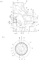
- FIG. 1 is a sectional view showing an example motor.
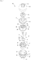
- FIG. 2 is an exploded perspective view showing the example motor.
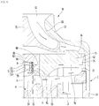
- FIG. 3 is an enlarged sectional view of portion A of FIG. 1 .
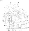
- FIG. 4 is a view showing an example flow of air when the motor dissipates heat of an example bearing in the motor.
- FIG. 5 is a cross-sectional view when an example bearing supporter is elastically deformed by the bearing.
- the motor M of this implementation includes a motor body 1, a rotating shaft 3, a bearing 5, a bracket 8, and a bearing supporter 9.
- the motor M is configured such that air in the motor M passes between the bearing 5 and the bracket 8 and is then discharged to the outside of the bracket 8.
- an example bearing heat dissipation flow path S6 through which air passes is formed between the outer surface of the bearing 5 and the inner surface of the bracket 8.
- the bearing supporter 9 having a plurality of pores H formed therein is disposed in the bearing heat dissipation flow path S6.
- a bracket through-hole 87 through which air passing through the plurality of pores H is discharged to the outside of the bracket 8 is formed in the bracket 8.
- Air of the bearing 5 is transferred to the bracket 8 through the bearing supporter 9.
- Air in the motor M is introduced into the bearing heat dissipation flow path S6 through the plurality of pores H formed in the bearing supporter 9, and dissipates heat of the bearing 5, the bearing supporter 9, and the bracket 8 while passing through the bearing heat dissipation flow path S6.
- the air of the bearing heat dissipation flow path S6 gets out of the bracket 8 by passing through the bracket through-hole 87.
- the motor body 1 may form an external appearance of the motor M.
- An air inlet 11 through which external air is suctioned into the motor body 1 may be formed in the motor body 1.
- a space in which a stator 2, a rotor 4, the rotating shaft 3, the bearing 5, the bracket 8, and an impeller 71 are accommodated may be formed inside the motor body 1.
- An air outlet 12 through which the air in the motor M is discharged to the outside of the motor body 1 may be formed in the motor body 1.
- the motor body 1 may be configured as an assembly of a plurality of members.
- the motor body 1 may include an impeller cover 13 in which the air inlet 11 is formed.
- the motor body may further include a motor housing 14 in which the air outlet 12 is formed.
- the impeller cover 13 may be coupled to the motor housing 14, and the motor housing 14 may constitute the motor body 1 together with impeller cover 13.
- the motor body 1 may further include a separate frame disposed between the impeller cover 13 and the motor housing 14, and each of the impeller cover 13 and the motor housing 14 may be coupled to the frame.
- bracket 8 may be disposed between the impeller cover 13 and the motor housing 14, and each of the impeller cover 13 and the motor housing 14 may be coupled to the bracket 8.
- the bracket 8 may constitute a portion of the motor body 1.
- the impeller cover 13 may surround the outer circumference of the impeller 71.
- the impeller cover 13 can protect the impeller 71 by surrounding the outer circumference of the impeller 71.
- the impeller cover 13 may have an open surface toward the motor housing 14.
- the impeller cover 13 may be disposed to cover the open surface of the motor housing 14.
- the impeller cover 13 may be coupled to the motor housing 14 or the bracket 8 using a fastening member such as a screw, for example, or may be screw-coupled to the motor housing 14 or the bracket 8.
- the air inlet 11 may be formed smaller than the surface opposite to the motor housing 14 in the impeller cover 13.
- the inner circumferential surface of the impeller cover 13 may be spaced apart from the impeller 71, and air driven by the impeller 71 may flow between the inner circumferential surface of the impeller cover 13 and the impeller 71.
- the motor housing 14 may have a hollow cylindrical shape having an open surface.
- the air outlet 12 through which air in the motor housing 14 is discharged to the outside may be formed in the motor housing 14.
- the air outlet 12 may be formed in plural numbers in the motor housing 14.
- the motor M may further include the stator 2 mounted in the motor body 1 and the rotor 4 mounted to the rotating shaft 3.
- the stator 2 may be mounted in the motor body 1.
- the stator 2 may be mounted to the motor housing 14 to surround the outer circumference of the rotor 4.
- the stator 2 may be mounted to the motor housing 14 using a fastening member such as a screw.
- the stator 2 may be formed in a hollow cylindrical shape.
- the stator 2 may be mounted to surround the outer circumference of the rotor 4.
- the stator 2 may be configured as an assembly of a plurality of members.
- the stator 2 may include a stator core 21, a pair of insulator 22 and 23 coupled to the stator core 21, and a coil 24 disposed at the insulators 22 and 23.
- the rotor 4 and the bearing 5 may be mounted to the rotating shaft 3, and the rotating shaft 3 may constitute a rotating shaft assembly R together with the rotor 4 and the bearing 5.
- the rotating shaft 3 may be disposed long from the inside of the motor housing 14 to the inside of the impeller cover 13. A portion of the rotating shaft 3 may be located inside the motor housing 14, and another portion of the rotating shaft 3 may be located inside the impeller cover 13.
- the rotating shaft 3 is rotated together with the rotor 4, and may be supported by the bearing 5.
- the rotating shaft 3 may be rotatably located inside the motor body 1.
- the rotating shaft 3 may be rotated by the rotor 4 in the state in which the rotating shaft 3 is supported by the bearing 5.
- the impeller 71 may be connected to the rotating shaft 3. When the rotating shaft 3 rotates, the impeller 71 may be rotated inside the impeller cover 13.
- An impeller connection part 32 to which the impeller 71 is connected may be formed at the rotating shaft 3.
- the impeller connection part 32 may be formed at a position spaced apart from a part 31 surrounded by the rotor 4.
- the impeller connection part 32 may be formed at an end portion of the rotating shaft 3.
- a second bearing mounting part at which a second bearing 6 which will be described later is mounted may be formed at the rotating shaft 3.
- the rotor 4 may be mounted to surround a portion of the rotating shaft 3.
- the rotor 4 may be rotatably located inside the stator 2.
- the rotor 4 may be formed in a hollow cylindrical shape.
- the rotor 4 may include an iron core 41 fixed to the rotating shaft 3, a magnet 42 installed at the iron core 41, and a pair of end plates 43 and 44 that fix the magnet 42.
- the rotor 4 may be mounted to surround the part 31 between one end and the other end of the rotating shaft 3.
- the rotor 4 may be mounted between the impeller connection part 32 and the second bearing mounting part.
- the bearing 5 may be accommodated inside the bracket 8, and may support the rotating shaft 3.
- the bearing 5 may be accommodated inside the bracket 8 together with the bearing supporter 9.
- the bearing 5 may include an inner rim 51 fixed to the rotating shaft 3, an outer rim 52 spaced apart from the inner rim 51, and a rolling member 53 disposed between the inner rim 51 and the outer rim 52.
- the bearing 5 may be one of a roller bearing and a ball bearing.
- the bearing 5 may be configured as a ball bearing in which the rolling member 53 is configured as a ball to have high performance in high-speed rotation.
- the external diameter D1 of the outer rim 52 of the bearing 5 may be smaller than the internal diameter D2 of a bearing supporter housing part 81 which will be described later.
- the bearing heat dissipation flow path S6 may be formed between the outer circumferential surface of the outer rim 52 of the bearing 5 and the inner circumferential surface of the bearing supporter housing part 81.
- the bearing heat dissipation flow path S6 may be formed in a hollow cylindrical shape between the outer rim 52 of the bearing 5 and the bearing supporter housing part 81.
- the motor M may further include an O-ring 54 fixed to the rotating shaft 3, the O-ring 54 restricting the bearing 5.
- the O-ring 54 may be fixed to the rotating shaft 3, and may constitute a rotating shaft assembly (or rotor assembly) together with the rotating shaft 3 and the rotor 4.
- the O-ring 54 may be located between the bearing 5 and the rotor 4 in the length direction of the rotating shaft 3.
- the O-ring 54 may be a bearing stopper that restricts the bearing 5 from moving toward the rotor 4.
- the O-ring 54 may be fixed to the rotating shaft 3 to come in contact with a portion of the bearing 5. At least one portion of the O-ring 54 may face the inner rim 51 of the bearing 5. The O-ring 54 may come in contact with the inner rim 51 of the bearing 5. The O-ring 54 may be a bearing stopper that restricts the inner rim 51 of the bearing 5 from sliding toward the rotor 4.
- the external diameter D3 of the O-ring 54 may be smaller than the internal diameter D4 of the bearing supporter 9.
- the O-ring 54 may be located inside the bearing supporter 9. When the rotating shaft 3 rotates, the O-ring 54 may be rotated in an empty space formed inside the bearing supporter 9.
- a gap G1 may be formed between the outer circumference of the O-ring 54 and the bearing supporter 9, and the O-ring 54 and the bearing supporter 9 may not come in contact with each other.
- the O-ring 54 and the bearing supporter 9 come in contact with each other, at least one of the O-ring 54 and the bearing supporter 9 may be abraded.
- the lifespan of each of the O-ring 54 and the bearing supporter 9 can be maximized.
- the O-ring 54 may be mounted to the rotating shaft 3, come in contact with the inner rim 51 of the bearing 5, and be spaced apart from the bearing supporter 9.
- the O-ring 54 may include an inner ring 55 coming in contact with the inner rim 51 of the bearing 5 and an outer ring 56 spaced apart from the outer rim 52 of the bearing 5.
- the outer circumference of the outer ring 56 may be the outer circumference of the O-ring 54
- the external diameter of the outer ring 56 may be the external diameter D3 of the O-ring 54.
- a portion of the rotating shaft 3, which is located inside the motor housing 14, may be directly supported by the motor housing 14.
- a rotating shaft support part rotatably supporting the rotating shaft 3 may be formed in the motor housing 14.
- the rotating shaft support part may be formed in the motor housing 14 to surround the outer circumference of the rotating shaft 3.
- a lubrication medium for preventing abrasion between the rotating shaft 3 and the rotating shaft support part, such as a lubricant, may be provided to at least one of the rotating shaft 3 and the rotating shaft support part.
- the portion of the rotating shaft 3, which is located inside the motor housing 14, may be supported through the second bearing 6.
- the motor M may further include the second bearing 6 installed at the rotating shaft 3, and the second bearing 6 may rotatably support the rotating shaft 3.
- the second bearing 6 may be installed at the rotating shaft 3 to be spaced apart from the bearing 5.
- the bearing 5 and the second bearing 6 may rotatably support the rotating shaft 3 at positions spaced apart from each other. In this case, the weight of the rotating shaft 3 may be distributed by the bearing 5 and the second bearing 6.
- the bearing 5 and the second bearing 6 may be mounted together between the rotor 4 and the impeller 71.
- the bearing 5 and the second bearing 6 may be mounted to be spaced apart from each other in the axial direction of the rotating shaft 3 between the rotor 4 and the impeller 71.
- the bearing 5 and the second bearing 6 may be mounted to be spaced apart from each other with the rotor 4 interposed therebetween.
- the bearing 5 and the second bearing 6 may support the rotating shaft 3 by efficiently distributing the weight of the rotating shaft 3.
- the maximum weight applied to the bearing 5 and the second bearing 6 is lower than that when the bearing 5 and the second bearing 6 are mounted together between the rotor 4 and the impeller 71, and the lifespan of each of the bearing 5 and the second bearing 6 is longer than that when the bearing 5 and the second bearing 6 are mounted together between the rotor 4 and the impeller 71.
- a separate space for allowing the bearing 5 and the second bearing 6 to be spaced apart from each other may not be required, and the motor M can be compact as compared with when the bearing 5 and the second bearing 6 are mounted together between the rotor 4 and the impeller 71.
- the second bearing 6 may be located between the rotating shaft 3 and the motor housing 14 to support the rotating shaft 3. In this case, the second bearing 6 may be spaced apart from the bearing 5 with the rotor 4 interposed therebetween.
- the bearing 5 may be a load-side bearing close to the impeller 71, and the second bearing 6 may be a non-load-side bearing distant from the impeller 71, or vice versa.
- the bearing 5 when the motor M includes both of the bearing 5 and the second bearing 6, the bearing 5 may be a bracket-side bearing surrounded by the bracket 8, and the second bearing 6 may be a motor housing-side bearing surrounded by motor housing 14.
- the bearing 5 may be a first bearing mounted between the impeller 71 and the second bearing 6, for example, or between the impeller 71 and the rotor 4, and the second bearing 6 may be an end bearing mounted at an end portion of the rotating shaft 3, which is opposite to the impeller 71.
- the second bearing 6 When the rotating shaft 3 is supported by the second bearing 6, the second bearing 6 may be mounted to the rotating shaft 3 to be located inside the motor housing 14.
- a hollow part 15 larger than the rotating shaft 3 may be formed in the motor housing 14.
- the hollow part 15 has an internal diameter greater than a diameter of the rotating shaft 3.
- the motor housing 14 may include a body part 16 from which the hollow part 15 protrudes.
- the hollow part 15 may be formed larger than the second bearing 6.
- the second bearing 6 may be directly supported by the motor housing 14, or may be supported by the motor housing 14 with a separate elastic member interposed therebetween.
- the outer circumference of the second bearing 6 may come in contact with the hollow part 15 to be supported by the hollow part 15.
- the second bearing 6 may include an inner rim 61 fixed to the rotating shaft 3, an outer rim 62 spaced apart from the inner rim 61, and a rolling member 63 disposed between the inner rim 61 and the outer rim 62.
- the second bearing 6 may be one of a roller bearing or a ball bearing.
- the second bearing 6 may be configured as a ball bearing in which the rolling member 63 is configured as a ball to have high performance in high-speed rotation.
- the inner rim 61 of the second bearing 6 may be fixed to the rotating shaft 3, and the outer rim 62 of the second bearing 6 may come in contact with the hollow part 15 to be fixed to the hollow part 15.
- the motor M may further include a second O-ring 64 fixed to the rotating shaft 3, the second O-ring 64 supporting the second bearing 6.
- the second O-ring 64 may be fixed to the rotating shaft 3, and may constitute a rotating shaft assembly (or rotor assembly) together with the rotating shaft 3 and the rotor 4.
- the second O-ring 64 may be located between the second bearing 6 and the rotor 4 in the length direction of the rotating shaft 3.
- the second O-ring 64 may be a second bearing stopper that restricts the second bearing 6 from moving toward the rotor 4.
- the second O-ring 64 may be fixed to the rotating shaft 3 to come in contact with a portion of the second bearing 6. At least one portion of the second O-ring 64 may face the inner rim 61 of the second bearing 6. The second O-ring 64 may come in contact with the inner rim 61 of the second bearing 6. The second O-ring 64 may be a bearing stopper that restricts the inner rim 61 of the second bearing 6 from sliding toward the rotor 4.
- the second O-ring 64 may be mounted to the rotating shaft 3, come in contact with the inner rim 61 of the second bearing 6, and be spaced apart from the hollow part 15.
- the second O-ring 64 may include an inner ring 65 coming in contact with the inner rim 61 of the second bearing 6 and an outer ring 66 spaced apart from the outer rim 62 of the second bearing 6.
- the impeller 71 may be connected to the rotating shaft 3.
- the impeller 71 may be rotated together with the rotating shaft 3 in the state in which the impeller 71 is connected to the rotating shaft 3.
- the impeller 71 may be located between the impeller cover 13 and a diffuser 74 which will be described later.
- a gap S1 through which air flowed by the impeller 71 passes may be formed between the impeller 71 and the impeller cover 13.
- the motor M may further include the diffuser 74 that guides the air flowed by the impeller 71.
- the air flowed by the impeller 71 may be guided by the diffuser 74, and the air guided by the diffuser 74 dissipates heat of the bearing 5 while passing between the bearing 5 and the bracket 8.
- the air flowed by the impeller 71 may be flowed into the bearing supporter 9 by the diffuser 74.
- the air flowed into the bearing supporter 9 may be introduced into the pores H of the bearing supporter 9 to pass through the bearing heat dissipation flow path S6, and then discharged from the bearing heat dissipation flow path S6 to the outside of the bracket 8 through the bracket through-hole 87.
- the diffuser 74 may be disposed inside the impeller cover 13.
- the diffuser 74 may be mounted to at least one of the impeller cover 13 and the bracket 8.
- a gap S2 through which air guided by the diffuser 74 passes may be formed between the diffuser 74 and the impeller cover 13.
- the diffuser 74 may include a body part 75 having a smaller size than the impeller cover 13, a diffuser vane 76 protruding from the outer circumference of the body part 75, and a guide vane 77 guiding air flowed by the diffuser vane 76.
- the diffuser vane 76 may be formed to change the dynamic pressure of air passing through the impeller 71 to static pressure.
- the guide vane 77 may guide air of which pressure is increased by the diffuser vane 76 toward at least one of the bearing supporter 9 and the rotor 4.
- the guide vane 77 may guide air toward a gap S4 between the bearing supporter 9 and the rotor 4.
- the air guided by the guide vane 77 may pass through a gap S3 between the diffuser 74 and the stator 2 and then pass through the gap S4 between the bearing supporter 9 and the rotor 4.
- Some of the air flowed by the guide vane 77 may be flowed into the bearing supporter 9 to dissipate heat of the bearing 5, the bearing supporter 9, and the bracket 8. Some of the air flowed by the guide vane 77, for example, air that is not introduced into the bearing supporter 9 may be flowed into a gap S5 between the rotor 4 and the stator 2 to dissipate heat of the rotor 4 and the stator 2.
- the bracket 8 may be installed in the motor body 1.
- the bracket 8 may be installed in the motor body 1 to be located inside the motor body 1.
- the bracket 8 may be coupled to at least one of the motor housing 14, the impeller cover 13, and the diffuser 74.
- the bracket 8 may simultaneously accommodate the bearing 5 and the bearing supporter 9 therein.
- the bracket 8 may include the bearing supporter housing part 81 surrounding the outer circumference of the bearing supporter 9.
- the bracket 8 may include a cover part 82 formed at the bearing supporter housing part 81.
- the bracket 8 may include a fastening part 84 fastened to at least one of the motor housing 14 and the impeller cover 13.
- the bracket 8 may include at least one connection part 86 that connects the fastening part 84 and the bearing supporter housing part 81.
- the internal diameter D2 of the bearing supporter housing part 81 may be greater than the external diameter D1 of the outer rim 52 of the bearing 5.
- the bearing supporter housing part 81 may be formed larger than the O-ring 54, and the internal diameter of the bearing supporter housing part 81 of the bracket 8 may be greater than the external diameter of the O-ring 54.
- the O-ring 54 may be rotated in a space formed inside the bearing supporter housing part 81.
- a gap may be formed between the inner circumferential surface of the bearing supporter housing part 81 of the bracket 8 and the outer circumference of the O-ring 54. The gap may be greater than the thickness of the bearing supporter 9.
- the cover part 82 may cover between the inner rim 51 and the outer rim 52 of the bearing 5 and face the impeller 71.
- the cover part 82 may be formed in a shape bent from the bearing supporter housing part 81.
- the cover part 82 may be formed in a ring shape at one end of the bearing supporter housing part 81.
- a rotating shaft through-hole 83 through which the rotating shaft 3 rotatably passes may be formed in the cover part 82.
- the diameter D5 of the rotating shaft through-hole 83 may be smaller than the internal diameter D2 of the bearing supporter housing part 81.
- the cover part 82 may be spaced apart from the O-ring 54, and a bearing accommodation space in which the bearing 5 is accommodated may be formed between a surface of the O-ring 54 facing the bearing 5 and a surface of the cover part 82 facing the bearing 5.
- the fastening part 84 may be formed in a ring shape.
- the fastening part 84 may be fastened to at least one of the motor housing 14 and the impeller cover 13 using a fastening member 85 such as screw.
- the fastening part 84 may be formed larger than the bearing supporter housing part 81.
- a first gap S7 through which air having passed through the bracket through-hole 87 passes may be formed between the cover part 82 and the impeller 71.
- a second gap S8 through which the air having passed through the first gap S7 is discharged toward a space between the diffuser 74 and the impeller cover 13 may be formed between the diffuser 74 and the impeller 71.
- the bracket through-hole 87 may be formed in at least one of the bearing supporter housing part 81 and the cover part 82. Also, the bracket through-hole 87 is formed to face at least some of the plurality of pores H.
- At least one bracket through-hole 87 may be formed in an area of the cover part 82, which faces the bearing supporter 9.
- the bracket through-hole 87 may be formed to face each of the first gap S7 and the bearing supporter 9.
- the bearing supporter 9 may have a hollow cylindrical shape.
- the inner surface of the bearing supporter 9 may come in contact with the outer surface of the bearing 5, and the outer surface of the bearing supporter 9 may come in contact with the inner surface of the bracket 8.
- a cylindrical empty space may be formed inside the bearing supporter 9.
- the bearing supporter 9 may be disposed between the outer rim 52 of the bearing 5 and the bearing supporter housing part 81 of the bracket 8.
- the bearing supporter 9 may be disposed to come in contact with at least one of the outer rim 52 of the bearing 5 and the bearing supporter housing part 81 of the bracket 8.
- the inner surface of the bearing supporter 9 may come in contact with the outer surface of the outer rim 52 of the bearing 5, and the outer surface of the bearing supporter 9 may come in contact with the inner surface of the bearing supporter housing part 81 of the bracket 8.
- the bearing supporter 9 may be formed to allow air to pass therethrough and to be elastically deformed by the bearing 5.
- the bearing supporter 9 may be elastically deformed by the plurality of pores H. In this case, the bearing supporter 9 may adjust the position of the bearing 5 to a regular position in the state in which the bearing supporter 9 is elastically deformed by the bearing 5.
- the bearing 5 and the second bearing 6 may be mounted such that their center axes correspond to each other.
- the abrasion of any one of the bearing 5 and the second bearing 6 may be large.
- the center axis HI of the bearing supporter housing part 81 and the center axis of the hollow part 15 do not correspond to each other due to an assembly tolerance of the motor housing 14 and the bracket 8.
- the error in concentricity between the bearing 5 and the second bearing 6 may be large.
- the bearing supporter 9 may adjust the position of the bearing 5 to be aligned with the position of the second bearing 6 such that the center axis B1 of the bearing 5 and the center axis of the second bearing 6 maximally correspond to each other.
- the bearing supporter 9 may be disposed between the bracket 8 and the bearing 5, and may support bearing 5.
- the bearing supporter 9 may be press-fitted between the bracket 8 and the bearing 5.
- the concentricities of the bearing 5 and the second bearing 6 may not correspond to each other due to the assembly tolerance of the motor housing 14 and the bracket 8.
- the bearing supporter 9 may support the bearing 5 such that the center axis B1 of the bearing 5 and the center axis of the second bearing 6 maximally correspond to each other in a state in which a portion of the bearing supporter 9 is elastically compressed.
- the bearing 5, as shown in FIG. 5 may pressurize a portion of the bearing supporter 9 in a state in which the center axis B1 of the bearing 5 and the center axis HI of the bearing supporter housing part 81 do not correspond to each other.
- the bearing supporter 9 may support the bearing 5 in the state in which the portion pressurized by the bearing 5 is compressed.
- the bearing supporter 9 may include a metal wire mesh in which at least one metal wire 91 is irregularly tangled.
- the height L1 of the bearing supporter 9 may be higher than the height L2 of the bearing 5.
- a portion of the bearing supporter 9 may be disposed between the outer rim 52 of the bearing 5 and the bearing supporter housing part 81 of the bracket 8.
- the internal diameter D4 of the bearing supporter 9 may be equal to or smaller than the external diameter D1 of the outer rim 52 of the bearing 5.
- the external diameter of the bearing supporter 9 may be equal to or smaller than the internal diameter D2 of the bearing supporter housing part 81 of the bracket 8.
- a portion of the bearing supporter 9 may be press-fitted between the outer rim 52 of the bearing 5 and the bearing supporter housing part 81 of the bracket 8.
- the portion of the bearing supporter 9 may be fixed by the outer rim 52 of the bearing 5 and the bearing supporter housing part 81 of the bracket 8 in the state in which it is press-fitted.
- the bearing supporter 9 may include a first area 9A that faces the bearing 5 and a second area 9B that does not face the bearing 5.
- the first area 9A of the bearing supporter 9 may face the outer rim 52 of the bearing 5 and the bearing supporter housing part 81.
- the second area 9B of the bearing supporter 9 may include an area that faces the O-ring 54.
- the second area 9B of the bearing supporter 9 may further include an area that does not face both of the outer surface of the bearing 5 and the O-ring 54.
- the bearing supporter 9 may come in contact with the cover part 82. When the bearing supporter 9 comes in contact with the cover part 82, the bearing supporter 9 may be held by the cover part 82, and the mounting position of the bearing supporter 9 may be determined by the cover part 82.
- the bearing supporter may be protected by the outer rim 52 of the bearing 5, the bearing supporter housing part 81, and the cover part 82.
- Heat of the bearing 5 may be transferred to the metal wire 91, and the heat transferred to the metal wire 91 may be transferred to the bracket 8 through a bracket contact part 92 of the metal wire 91, which comes in contact with the bracket 8.
- the heat transferred to the metal wire 91 may be dissipated in an air cooling manner through the second area 9B of the metal wire 91, which does not face the bearing 5.
- the heat of the bearing 5 may be transferred to the bracket 8 through the bearing supporter 9, and the heat transferred to the bracket 8 may be transferred to air in the motor M through the bearing supporter 9.
- the plurality of pores H may be open in the radial and axial directions of the bearing supporter 9.
- the plurality of pores H may include at least one first pore that faces the outer rim 52 of the bearing and at least one second pore that does not face the outer rim 52 of the bearing 5.
- the air guided by the diffuser 74 may be introduced into the bearing supporter 9 through the second pore, and then dissipate each of the bearing 5, the bearing supporter 9, and the bracket 8 while passing through the first pore.
- the bearing supporter 9 may have an end part 95 opposite to the rotor 4. Air flowed in the gap S4 between the bearing support 9 and the rotor 4 in the air in the motor M may be introduced into the bearing supporter 9 through the end part 95 of the bearing supporter 9, which is opposite to the rotor 4.
- the rotating shaft 3 may be rotated, and the impeller 71 may be rotated together with the rotating shaft 3.
- air outside the motor M may be suctioned into the impeller 71 through the air inlet 11.
- the air suctioned into the impeller 71 may be flowed into the diffuser 74 by the impeller 71, and the air flowed into the diffuser 74 may pass through the gap S2 between the diffuser 74 and the impeller cover 13 while being guided by the diffuser 74.
- the air guided by the diffuser 74 may be sequentially guided by the diffuser vane 76 and the guide vane 77.
- the air guided by the guide vane 77 may pass through the gap S3 between the diffuser 74 and the stator 2. Some of the air passing through the gap S3 between the diffuser 74 and the stator 2 may be introduced into the bearing supporter 9 by passing through the gap S4 between the bearing supporter 9 and the rotor 4, and some of the air passing through the gap S3 between the diffuser 74 and the stator 2 may be flowed into the gap S5 between the rotor 4 and the stator 2.
- the air introduced into the bearing supporter 9 may be introduced into the bearing heat dissipation flow path S6 by passing through the plurality of pores H formed in the bearing supporter 9.
- the air introduced into the bearing supporter 9 may come in contact with each of the bearing 5, the bearing supporter 9, and the bracket 8 while passing through the plurality of pores H, and absorb heat of each of the bearing 5, the bearing supporter 9, and the bracket 8.
- the air passing through the plurality of pores H formed in the bearing supporter 9 may be discharged to the outside of the bracket 8 by passing through the bracket through-hole 87, be introduced into the first gap S7 between the cover part 82 and the impeller 71 to pass through the first gap S7, and be then introduced into the second gap S8 between the diffuser 74 and the impeller 71 to pass through the second gap S8.
- the air passing through the second gap S8 may be flowed into the gap S2 between the diffuser 74 and the impeller cover 13 to be mixed with the air guide by the impeller 71, and the mixed air may be guided to the diffuser 74.
- FIG. 6 is a view showing an example flow of air when a motor dissipates heat of an example bearing.
- An example bracket 8 may include a bearing supporter housing part 81 surrounding a bearing supporter 9, and a bracket through-hole 88 may be formed in the bearing supporter housing part 81.
- a diffuser through-hole 78 that allows a space between a diffuser 74 and an impeller cover 13 to communicate with the bracket through-hole 88 may be formed in the diffuser 74.
- the bracket through-hole 88 of this implementation may be formed to be open in the radial direction of the bearing supporter housing part 81.
- the diffuser through-hole 78 may be formed to be open in the radial direction of the diffuser 74, for example, or a body part 75.
- bracket through-hole 88 and the diffuser through-hole 78 are identical or similar to those of the aforementioned implementation. Therefore, the components except the bracket through-hole 88 and the diffuser through-hole 78 are designated by like reference numerals, and their detailed descriptions will be omitted.
- Air introduced into the bearing supporter 9 may absorb heat of each of a bearing 5, the bearing supporter 9, and a bracket 8 while passing through the plurality of pores H.
- the air may sequentially pass through the bracket through-hole 88 formed in the bearing supporter housing part 81 and the diffuser through-hole 78 formed in the diffuser 74 and be then flowed into a gap S2 between the diffuser 74 and the impeller cover 13.
- the air flowed into the gap S2 between the diffuser 74 and the impeller cover 13 may be mixed with air guided by the impeller cover 13 and then guided to the diffuser 74.
- FIG. 7 is a view showing an example flow of air when another example motor dissipates heat of an example bearing.
- An example bracket 8 may include a bearing supporter housing part 81 surrounding a bearing supporter 9, and a cover part 82 formed in the bearing supporter housing part 81 to cover between inner and outer rims 51 and 52 of a bearing 5.
- At least one first bracket through-hole 87 that faces at least one portion of the bearing supporter 9 may be formed in the cover part 82, and at least one second bracket through-hole 88 may be formed in the bearing supporter housing part 81.
- a diffuser through-hole 78 that allows a space between a diffuser 74 and an impeller cover 13 to communicate with the second bracket through-hole 88 may be formed in the diffuser 74.
- the first bracket through-hole 87 and the second bracket through-hole 88 may be open in directions different from each other.
- the first bracket through-hole 87 may be open in a direction parallel to a rotating shaft 3 in the cover part 82.
- the second bracket through-hole 88 may be open in the radial direction of the diffuser 74 in the bearing supporter housing part 81.
- the second bracket through-hole 88 may be open in a direction perpendicular to the rotating shaft 3 in the bearing supporter housing part 81.
- the motor may include a first heat dissipation flow path including a bearing heat dissipation flow path S6, the first bracket through-hole 87, a first gap S7, and a second gap S8, and a second heat dissipation flow path including the bearing heat dissipation flow path S6, the second bracket through-hole 88, and the diffuser through-hole 78.
- the first heat dissipation flow path and the second heat dissipation flow path may be separated from each other at the bearing heat dissipation flow path S6. Air inside the motor M can more reliably pass through the bearing heat dissipation flow path S6, and the heat dissipation performance of the bearing 5 can be maximized.
- FIG. 8 is a sectional view showing an example motor.
- FIG. 9 is an enlarged sectional view of portion B of FIG. 8 .
- FIG. 10 is a view showing an example flow of air when the motor dissipates heat of an example second bearing.
- an example hollow part 15 larger than a rotating shaft 3 may be formed in a motor housing 14, and a second bearing 6' of which external diameter D6 is smaller than the internal diameter D7 of the hollow part 15 may be mounted to the rotating shaft 3.
- a second bearing heat dissipation flow path S9 through which air passes may be formed between the inner surface of the hollow part 15 and the outer surface of the second bearing 6', and a second bearing supporter 9' in which a plurality of pores H are formed may be disposed in the second bearing heat dissipation flow path S9.
- the other components except the second bearing 6' and the second bearing supporter 9' and their operations are identical or similar to those of the aforementioned implementation. Therefore, the components except the second bearing 6' and the second bearing supporter 9' are designated by like reference numerals, and their detailed descriptions will be omitted.
- the motor may include both of the bearing supporter 9 and the second bearing supporter 9', and the bearing supporter 9 and the second bearing supporter 9' may align the bearing 5 and the second bearing 6' at positions different from each other.
- the position of the bearing 5 aligned by the bearing supporter 9 is identical to that of the aforementioned implementation, and therefore, its detailed description will be omitted.
- An example second O-ring 64 of this implementation may include an inner ring 65 mounted to the rotating shaft 3 and an outer ring 66 spaced apart from an outer rim 62 of the second bearing 6'. Also, the second O-ring 64 may be mounted to the rotating shaft 3 to be located inside the second bearing supporter 9'.
- a gap G2 may be formed between the outer circumference of the second O-ring 64 and the second bearing supporter 9'.
- the second O-ring 64 does not come in contact with the inner circumference of the second bearing supporter 9', and thus the abrasion of the second bearing supporter 9' and the second O-ring 64 can be minimized.
- the gap G2 can assist air passing through a gap S5 between a stator 2 and a rotor 4 to be introduced into the plurality of pores H formed in the second bearing supporter 9'.
- the second bearing 6' may pressurize a portion of the second bearing supporter 9' in a state in which the center axis B2 of the second bearing 6' does not correspond to the center axis H2 of the hollow part 15.
- the second bearing supporter 9' may support the second bearing 6' in the portion pressurized by the second bearing 6' is compressed.
- the center axis H2 of the hollow part 15 shown in FIG. 10 may not correspond to the center axis HI of the bearing supporter housing part 81 shown in FIG. 5 due to an assembly tolerance of a motor housing 14 and a bracket 8.
- the position of the second bearing 6' can be aligned together with the rotating shaft 3 in the state in which the second bearing 6' is supported by the second bearing supporter 9', and the concentricities of the bearing 5 and the second bearing 6' can correspond to each other.
- the concentricities of the bearing 5 and the second bearing 6' can correspond to each other.
- each of the bearing supporter 9 and the second bearing supporter 9' is elastically deformed according to the assembly tolerance of the motor housing 14 and the bracket 8, the concentricities of the bearing 5 and the second bearing 6' can correspond to each other.
- the position of the bearing 5 can be aligned by the bearing supporter 9, and the position of the second bearing 6' can be aligned by the second bearing supporter 9'.
- the concentricities of the bearing 5 and the second bearing 6' can smoothly correspond to each other, as compared with the aforementioned implementation.
- the second bearing supporter 9' may have a hollow cylindrical shape.
- the inner surface of the second bearing supporter 9' may come in contact with the outer surface of the second bearing 6', and the outer surface of the second bearing supporter 9' may come in contact with the inner surface of the hollow part 15.
- the second bearing supporter 9' may have an end part 95 opposite to the rotor 4.
- At least one air outlet 18 may be formed in an area facing the second bearing supporter 9'.
- the air outlet 18 may be formed in a body part 16 of the motor housing 14.
- the air passing through the gap S5 between the stator 2 and the rotor 4 can efficiently dissipate heat of each other the second bearing 6', the second bearing supporter 9', and the motor housing 14 while passing through the plurality of pores H formed in the second bearing supporter 9'.
Landscapes
- Engineering & Computer Science (AREA)
- General Engineering & Computer Science (AREA)
- Mechanical Engineering (AREA)
- Power Engineering (AREA)
- Physics & Mathematics (AREA)
- Thermal Sciences (AREA)
- Support Of The Bearing (AREA)
- Motor Or Generator Frames (AREA)
- Rolling Contact Bearings (AREA)
Description
- The present disclosure relates to a motor, and more particularly, to a motor including a bearing.
-
US 2007/096572 A1 describes an electric motor including a stator, a housing supporting the stator and having a bearing seat with an inner surface and an inner end, a bearing having an outer surface, a shaft rotatably supported by the bearing, and a rotor supported by the shaft. The motor also includes a tolerance ring having an interior surface, an exterior surface disposed against the bearing seat inner surface, and a plurality of elastic corrugations. Each of the elastic corrugations projects radially from the interior surface, defining a shoulder section disposed between the bearing and the inner end of the bearing seat. The shoulder section generates a spring force against the bearing to axially and radially support the bearing and to axially preload the bearing. -
EP 2 899 414 A1 -
DE 10 2005 010459 A1 relates to an additional electric motor having a rotor and a stator. -
US 5 059 042 describes an improved bearing retainer for a vacuum cleaner including a plurality of inwardly projecting retainer tabs for securing the bearing retainer in a fixed location relative to a vacuum cleaner motor housing and a bearing assembly, said bearing assembly being mounted on a motor shaft, which motor shaft projects through said vacuum cleaner motor housing. -
US 2015/198084 A1 describes an exhaust gas turbocharger for an internal combustion engine may include a rotor with a turbine wheel of a turbine, a compressor wheel of a compressor and a shaft. The shaft may be connected to the turbine wheel and to the compressor wheel in a rotationally fixed manner. A bearing cartridge may be included for mounting the rotor in a housing. The bearing cartridge may have an inner sleeve arranged on the shaft axially between the turbine wheel and the compressor wheel with respect to an axis of rotation and an outer sleeve arranged coaxial thereto. The outer sleeve may be rotatably mounted on the inner sleeve via at least one rolling body. At least two damping rings may be included which are coaxially arranged on the outer sleeve axially spaced from one another and supported on a respective bearing section of the housing. -
US 4 514 458 A describes material, which is formed of a compressed and substantially homogeneous mass of randomly extending stainless steel wires which, prior to compression of the mass, contain helical coils and are substantially free from stress risers. The material is highly durable, and under compression loading has substantially isotropic and linear stress/strain properties at significantly differing strain levels. - A motor may be installed in a household appliance such as a vacuum cleaner. For example, a motor in a vacuum cleaner may generate a driving force for suctioning dust into a dust collecting part.
- An example motor may include a motor housing, a stator installed in the motor housing, a rotor rotated by the stator, and a rotating shaft having the rotor mounted thereon.
- In some examples, the rotating shaft of the motor may be rotatably supported by at least one bearing. The rotating shaft may be rotated at high speed while being supported by the bearing.
- In some cases, when the temperature in the motor increases, the performance of the motor may be deteriorated, and therefore, the temperature in the motor may be maintained such that the motor is not overheated.
- Heat of the bearing is one of several factors that can increase the temperature in the motor, and therefore, the heat of the bearing may be dissipated such that the bearing is not overheated. For example, when the rotating shaft is rotated at high speed in the motor, the bearing may be overheated. In this case, the lifespan of the bearing may be shortened.
- The object is solved by the features of the independent claims. Preferred embodiments are given in the dependent claims.
- A motor is provided to enable heat of a bearing to be efficiently dissipated by air flowing in the motor.
- The motor includes a bearing supporter that can align the position of a bearing while assisting the heat dissipation of the bearing.
- According to one aspect of subject matter described in this application, a motor includes a motor body, a bracket installed in the motor body, a rotating shaft, a bearing accommodated inside the bracket and supporting the rotating shaft, and a bearing supporter defining a plurality of pores. The bracket and the bearing define a bearing heat dissipation flow path between an outer surface of the bearing and an inner surface of the bracket, and the bearing heat dissipation flow path is configured to pass air therethrough. The bearing supporter is disposed in the bearing heat dissipation flow path, and the bracket defines a bracket through-hole configured to discharge air that has passed through the plurality of pores of the bearing supporter. A stator may be installed in the motor housing, wherein the stator surrounding the rotor.
- Implementations according to this aspect may include one or more of following features. The bearing supporter may include a metal wire mesh in which at least one metal wire has one or more curved portions. The bearing supporter may have a hollow cylindrical shape, and the bearing supporter may have an inner surface that contacts the outer surface of the bearing, and an outer surface that contacts the inner surface of the bracket. In some implementations, the bracket through-hole faces one or more of the plurality of pores.
- According to another aspect of subject matter described in this application, a motor includes a motor housing, a rotating shaft assembly that includes a rotating shaft, a rotor, and a bearing in which the rotor and the bearing are mounted to the rotating shaft, a bearing supporter defining a plurality of pores, a stator installed in the motor housing, the stator surrounding the rotor, an impeller connected to the rotating shaft, an impeller cover that surrounds an outer circumference of the impeller and that defines an air inlet between the impeller and the impeller cover, a diffuser disposed inside the impeller cover, and a bracket coupled to at least one of the motor housing, the impeller cover, or the diffuser. The bearing and the bracket define a bearing heat dissipation flow path between an outer surface of the bearing and an inner surface of the bracket, and the bearing heat dissipation flow path is configured to pass air. The bearing supporter is disposed in the bearing heat dissipation flow path, the bracket defines a bracket through-hole facing one or more of the plurality of pores, and the bracket through-hole is configured to discharge air that has passed through the plurality of pores of the bearing supporter.
- Implementations according to this aspect, the bearing supporter may have an end part facing toward the rotor. The diffuser may include a guide vane configured to guide air toward a gap between the bearing supporter and the rotor. The bearing may include an inner rim fixed to the rotating shaft, an outer rim spaced apart from the inner rim, and a rolling member disposed between the inner rim and the outer rim.
- In some implementations, the bracket may include a bearing supporter housing part that surrounds an outer circumference of the bearing supporter, and a cover part that extends from the bearing supporter housing part and covers a portion of the bearing between the inner rim and the outer rim, the cover part being positioned opposite the impeller. The bracket through-hole may be defined in at least one of the bearing supporter housing part or the cover part.
- In some implementations, the cover part may define the bracket through-hole at a position that faces the bearing supporter. In some examples, the cover part and the impeller may define a first gap configured to receive the air that has passed through the bracket through-hole. The diffuser and the impeller may define a second gap that is configured to discharge the air that has passed through the first gap.
- In some implementations, the bracket through-hole may be located between the first gap and the bearing supporter, and face each of the first gap and the bearing supporter. The bearing may include an inner rim fixed to the rotating shaft, an outer rim spaced apart from the inner rim, and a rolling member disposed between the inner rim and the outer rim. The bracket may include a bearing supporter housing part that surrounds the bearing supporter, and the bearing supporter housing part may define the bracket through-hole. In some cases, the diffuser may define a diffuser through-hole that extends to a space between the diffuser and the impeller cover, and the diffuser through-hole is configured to communicate with the bracket through-hole.
- In some implementations, the bearing supporter may include a metal wire mesh in which at least one metal wire has one or more of curved portions. The bearing supporter may have a hollow cylindrical shape, and the bearing supporter may have an inner surface that contacts the outer surface of the bearing, and an outer surface that contacts the inner surface of the bracket.
- In some implementations, the bearing may include an inner rim fixed to the rotating shaft, an outer rim spaced apart from the inner rim, and a rolling member disposed between the inner rim and the outer rim. The bracket may include a bearing supporter housing part that surrounds the bearing supporter, and the bearing supporter may have an external diameter less than an internal diameter of the bearing supporter housing part. The bearing heat dissipation flow path may have a hollow cylindrical shape and be defined between an outer circumference of the outer rim and an inner circumference of the bearing supporter housing part.
- In some implementations, the motor may further include a second bearing mounted to the rotating shaft and a second bearing supporter defining a plurality of pores. The motor housing may include a hollow part that has an inner diameter greater than an outer diameter of the rotating shaft. The second bearing may have an outer diameter less than the inner diameter of the hollow part and is located between the rotating shaft and the hollow part. The hollow part and the second bearing may define a second bearing heat dissipation flow path between an inner surface of the hollow part and an outer surface of the second bearing in which the second bearing supporter may be disposed in the second bearing heat dissipation flow path.
- In some implementations, the motor housing may define at least one air outlet that faces the second bearing supporter. The second bearing supporter may have an end part facing toward the rotor.
- According to another aspect, a motor includes a motor housing, a rotating shaft assembly including a rotating shaft, a rotor, and a bearing in which the rotor and the bearing are mounted to the rotating shaft, a stator installed in the motor housing, the stator surrounding the rotor, an impeller connected to the rotating shaft, an impeller cover surrounding an outer circumference of the impeller and defining an air inlet between the impeller and the impeller cover, a diffuser disposed inside the impeller cover, a bracket mounted to at least one of the impeller cover, the motor housing, or the diffuser, and a bearing supporter disposed between the bracket and the bearing in which the bearing supporter defines a plurality of pores. The bearing includes an inner rim fixed to the rotating shaft, an outer rim spaced apart from the inner rim, and a rolling member disposed between the inner rim and the outer rim. The bracket includes a bearing supporter housing part that surrounds the bearing supporter, and a cover part that extends from the bearing supporter housing part and covers a portion of the bearing between the inner rim and the outer rim.
- The cover part defines at least one first bracket through-hole that faces at least a portion of the bearing supporter, and the bearing supporter housing part defines at least one second bracket through-hole. The diffuser defines a diffuser through-hole that extends to a space between the diffuser and the impeller cover, the diffuser through-hole being configured to communicate with the second bracket through-hole, and the first and second bracket through-holes extend toward different directions from each other.
- Implementations according to this aspect, the bearing supporter may have an inner surface that contacts an outer surface of the outer rim, and an outer surface that contacts an inner surface of the bearing supporter housing part.
- According to the present disclosure, as air inside the motor passes through the plurality of pores formed in the bearing supporter, heat of each of the bearing, the bearing supporter, and the bracket can be dissipated. In some implementations, it may be possible to minimize that the inside of the motor is overheated and to maximize the lifespan of the bearing.
- Further, it may be possible to efficiently dissipate heat of the bearing through a simple structure in which the bearing supporter is disposed between the bearing and the bracket, and the bracket through-hole is formed in the bracket.
- Further, when the position of the bearing is out of the regular position due to an assembly tolerance of the motor, or the like, the bearing can be aligned to the regular position by the bearing supporter that is elastically deformed by the bearing. In some implementations, the performance of the bearing can be maximized.
- Further, heat of the second bearing accommodated in the motor housing can be efficiently dissipated by air passing between the rotor and the stator.
- Further, as the air inside the motor is rapidly flowed through the two heat dissipation flow paths, the heat dissipation performance of the bearing can be maximized.
- The details of one or more implementations are set forth in the accompanying drawings and the description below. Other features will be apparent from the description and drawings, and from the claims.
-
-
FIG. 1 is a sectional view showing an example motor. -
FIG. 2 is an exploded perspective view showing the example motor. -
FIG. 3 is an enlarged sectional view of portion A ofFIG. 1 . -
FIG. 4 is a view showing an example flow of air in the motor dissipating heat of an example bearing. -
FIG. 5 is a cross-sectional view showing an example bearing supporter that is elastically deformed by the bearing. -
FIG. 6 is a view showing an example flow of air in an example motor dissipating heat of an example bearing. -
FIG. 7 is a view showing an example flow of air in another example motor dissipating heat of a bearing. -
FIG. 8 is a sectional view showing another example motor. -
FIG. 9 is an enlarged sectional view of portion B ofFIG. 8 . -
FIG. 10 is a view showing an example flow of air in the example motor dissipating heat of an example second bearing. - Hereinafter, exemplary implementations of the present disclosure will be described in detail with reference to the accompanying drawings.
-
FIG. 1 is a sectional view showing an example motor.FIG. 2 is an exploded perspective view showing the example motor.FIG. 3 is an enlarged sectional view of portion A ofFIG. 1 .FIG. 4 is a view showing an example flow of air when the motor dissipates heat of an example bearing in the motor.FIG. 5 is a cross-sectional view when an example bearing supporter is elastically deformed by the bearing. - The motor M of this implementation includes a
motor body 1, arotating shaft 3, abearing 5, abracket 8, and abearing supporter 9. - The motor M is configured such that air in the motor M passes between the
bearing 5 and thebracket 8 and is then discharged to the outside of thebracket 8. - In the motor M, an example bearing heat dissipation flow path S6 through which air passes is formed between the outer surface of the
bearing 5 and the inner surface of thebracket 8. In some implementations, the bearingsupporter 9 having a plurality of pores H formed therein is disposed in the bearing heat dissipation flow path S6. In some implementations, a bracket through-hole 87 through which air passing through the plurality of pores H is discharged to the outside of thebracket 8 is formed in thebracket 8. - Heat of the
bearing 5 is transferred to thebracket 8 through the bearingsupporter 9. Air in the motor M is introduced into the bearing heat dissipation flow path S6 through the plurality of pores H formed in the bearingsupporter 9, and dissipates heat of thebearing 5, the bearingsupporter 9, and thebracket 8 while passing through the bearing heat dissipation flow path S6. The air of the bearing heat dissipation flow path S6 gets out of thebracket 8 by passing through the bracket through-hole 87. - The
motor body 1 may form an external appearance of the motor M.An air inlet 11 through which external air is suctioned into themotor body 1 may be formed in themotor body 1. - A space in which a
stator 2, arotor 4, therotating shaft 3, thebearing 5, thebracket 8, and animpeller 71 are accommodated may be formed inside themotor body 1. Anair outlet 12 through which the air in the motor M is discharged to the outside of themotor body 1 may be formed in themotor body 1. - In some implementations, the
motor body 1 may be configured as an assembly of a plurality of members. Themotor body 1 may include animpeller cover 13 in which theair inlet 11 is formed. The motor body may further include amotor housing 14 in which theair outlet 12 is formed. Theimpeller cover 13 may be coupled to themotor housing 14, and themotor housing 14 may constitute themotor body 1 together withimpeller cover 13. - In some implementations, the
motor body 1 may further include a separate frame disposed between theimpeller cover 13 and themotor housing 14, and each of theimpeller cover 13 and themotor housing 14 may be coupled to the frame. - In the motor M, a portion of the
bracket 8 may be disposed between theimpeller cover 13 and themotor housing 14, and each of theimpeller cover 13 and themotor housing 14 may be coupled to thebracket 8. In this case, thebracket 8 may constitute a portion of themotor body 1. - The
impeller cover 13 may surround the outer circumference of theimpeller 71. Theimpeller cover 13 can protect theimpeller 71 by surrounding the outer circumference of theimpeller 71. - The
impeller cover 13 may have an open surface toward themotor housing 14. Theimpeller cover 13 may be disposed to cover the open surface of themotor housing 14. Theimpeller cover 13 may be coupled to themotor housing 14 or thebracket 8 using a fastening member such as a screw, for example, or may be screw-coupled to themotor housing 14 or thebracket 8. - The
air inlet 11 may be formed smaller than the surface opposite to themotor housing 14 in theimpeller cover 13. - The inner circumferential surface of the
impeller cover 13 may be spaced apart from theimpeller 71, and air driven by theimpeller 71 may flow between the inner circumferential surface of theimpeller cover 13 and theimpeller 71. - The
motor housing 14 may have a hollow cylindrical shape having an open surface. Theair outlet 12 through which air in themotor housing 14 is discharged to the outside may be formed in themotor housing 14. Theair outlet 12 may be formed in plural numbers in themotor housing 14. - In some implementations, the motor M may further include the
stator 2 mounted in themotor body 1 and therotor 4 mounted to therotating shaft 3. - The
stator 2 may be mounted in themotor body 1. Thestator 2 may be mounted to themotor housing 14 to surround the outer circumference of therotor 4. Thestator 2 may be mounted to themotor housing 14 using a fastening member such as a screw. Thestator 2 may be formed in a hollow cylindrical shape. Thestator 2 may be mounted to surround the outer circumference of therotor 4. - The
stator 2 may be configured as an assembly of a plurality of members. Thestator 2 may include astator core 21, a pair ofinsulator stator core 21, and acoil 24 disposed at theinsulators - The
rotor 4 and thebearing 5 may be mounted to therotating shaft 3, and therotating shaft 3 may constitute a rotating shaft assembly R together with therotor 4 and thebearing 5. - The
rotating shaft 3 may be disposed long from the inside of themotor housing 14 to the inside of theimpeller cover 13. A portion of therotating shaft 3 may be located inside themotor housing 14, and another portion of therotating shaft 3 may be located inside theimpeller cover 13. - The
rotating shaft 3 is rotated together with therotor 4, and may be supported by thebearing 5. Therotating shaft 3 may be rotatably located inside themotor body 1. Therotating shaft 3 may be rotated by therotor 4 in the state in which therotating shaft 3 is supported by thebearing 5. - The
impeller 71 may be connected to therotating shaft 3. When therotating shaft 3 rotates, theimpeller 71 may be rotated inside theimpeller cover 13. - An
impeller connection part 32 to which theimpeller 71 is connected may be formed at therotating shaft 3. Theimpeller connection part 32 may be formed at a position spaced apart from apart 31 surrounded by therotor 4. Theimpeller connection part 32 may be formed at an end portion of therotating shaft 3. - In some implementations, a second bearing mounting part at which a
second bearing 6 which will be described later is mounted may be formed at therotating shaft 3. - The
rotor 4 may be mounted to surround a portion of therotating shaft 3. Therotor 4 may be rotatably located inside thestator 2. Therotor 4 may be formed in a hollow cylindrical shape. - The
rotor 4 may include aniron core 41 fixed to therotating shaft 3, amagnet 42 installed at theiron core 41, and a pair ofend plates magnet 42. - The
rotor 4 may be mounted to surround thepart 31 between one end and the other end of therotating shaft 3. Therotor 4 may be mounted between theimpeller connection part 32 and the second bearing mounting part. - The
bearing 5 may be accommodated inside thebracket 8, and may support therotating shaft 3. Thebearing 5 may be accommodated inside thebracket 8 together with the bearingsupporter 9. - The
bearing 5 may include aninner rim 51 fixed to therotating shaft 3, anouter rim 52 spaced apart from theinner rim 51, and a rollingmember 53 disposed between theinner rim 51 and theouter rim 52. - The
bearing 5 may be one of a roller bearing and a ball bearing. Thebearing 5 may be configured as a ball bearing in which the rollingmember 53 is configured as a ball to have high performance in high-speed rotation. - The external diameter D1 of the
outer rim 52 of thebearing 5 may be smaller than the internal diameter D2 of a bearingsupporter housing part 81 which will be described later. In some implementations, the bearing heat dissipation flow path S6 may be formed between the outer circumferential surface of theouter rim 52 of thebearing 5 and the inner circumferential surface of the bearingsupporter housing part 81. The bearing heat dissipation flow path S6 may be formed in a hollow cylindrical shape between theouter rim 52 of thebearing 5 and the bearingsupporter housing part 81. - In some implementations, the motor M may further include an O-
ring 54 fixed to therotating shaft 3, the O-ring 54 restricting thebearing 5. - The O-
ring 54 may be fixed to therotating shaft 3, and may constitute a rotating shaft assembly (or rotor assembly) together with therotating shaft 3 and therotor 4. - The O-
ring 54 may be located between thebearing 5 and therotor 4 in the length direction of therotating shaft 3. In some examples, the O-ring 54 may be a bearing stopper that restricts thebearing 5 from moving toward therotor 4. - The O-
ring 54 may be fixed to therotating shaft 3 to come in contact with a portion of thebearing 5. At least one portion of the O-ring 54 may face theinner rim 51 of thebearing 5. The O-ring 54 may come in contact with theinner rim 51 of thebearing 5. The O-ring 54 may be a bearing stopper that restricts theinner rim 51 of thebearing 5 from sliding toward therotor 4. - The external diameter D3 of the O-
ring 54 may be smaller than the internal diameter D4 of the bearingsupporter 9. - The O-
ring 54 may be located inside the bearingsupporter 9. When therotating shaft 3 rotates, the O-ring 54 may be rotated in an empty space formed inside the bearingsupporter 9. - A gap G1 may be formed between the outer circumference of the O-
ring 54 and the bearingsupporter 9, and the O-ring 54 and the bearingsupporter 9 may not come in contact with each other. When the O-ring 54 and the bearingsupporter 9 come in contact with each other, at least one of the O-ring 54 and the bearingsupporter 9 may be abraded. In some implementations, when the O-ring 54 and the bearingsupporter 9 do not come in contact with each other, the lifespan of each of the O-ring 54 and the bearingsupporter 9 can be maximized. - The O-
ring 54 may be mounted to therotating shaft 3, come in contact with theinner rim 51 of thebearing 5, and be spaced apart from the bearingsupporter 9. - In some implementations, the O-
ring 54 may include aninner ring 55 coming in contact with theinner rim 51 of thebearing 5 and anouter ring 56 spaced apart from theouter rim 52 of thebearing 5. The outer circumference of theouter ring 56 may be the outer circumference of the O-ring 54, and the external diameter of theouter ring 56 may be the external diameter D3 of the O-ring 54. - In the motor M, a portion of the
rotating shaft 3, which is located inside themotor housing 14, may be directly supported by themotor housing 14. - When the
rotating shaft 3 is directly supported by themotor housing 14, a rotating shaft support part rotatably supporting therotating shaft 3 may be formed in themotor housing 14. The rotating shaft support part may be formed in themotor housing 14 to surround the outer circumference of therotating shaft 3. A lubrication medium for preventing abrasion between therotating shaft 3 and the rotating shaft support part, such as a lubricant, may be provided to at least one of therotating shaft 3 and the rotating shaft support part. - In the motor M, the portion of the
rotating shaft 3, which is located inside themotor housing 14, may be supported through thesecond bearing 6. The motor M may further include thesecond bearing 6 installed at therotating shaft 3, and thesecond bearing 6 may rotatably support therotating shaft 3. - The
second bearing 6 may be installed at therotating shaft 3 to be spaced apart from thebearing 5. - The
bearing 5 and thesecond bearing 6 may rotatably support therotating shaft 3 at positions spaced apart from each other. In this case, the weight of therotating shaft 3 may be distributed by thebearing 5 and thesecond bearing 6. - In the motor M, the
bearing 5 and thesecond bearing 6 may be mounted together between therotor 4 and theimpeller 71. In this case, thebearing 5 and thesecond bearing 6 may be mounted to be spaced apart from each other in the axial direction of therotating shaft 3 between therotor 4 and theimpeller 71. - In some implementations, in the motor M, the
bearing 5 and thesecond bearing 6 may be mounted to be spaced apart from each other with therotor 4 interposed therebetween. In this case, thebearing 5 and thesecond bearing 6 may support therotating shaft 3 by efficiently distributing the weight of therotating shaft 3. When thebearing 5 and thesecond bearing 6 are arranged with therotor 4 interposed therebetween, the maximum weight applied to thebearing 5 and thesecond bearing 6 is lower than that when thebearing 5 and thesecond bearing 6 are mounted together between therotor 4 and theimpeller 71, and the lifespan of each of thebearing 5 and thesecond bearing 6 is longer than that when thebearing 5 and thesecond bearing 6 are mounted together between therotor 4 and theimpeller 71. In some implementations, when thebearing 5 and thesecond bearing 6 are arranged with therotor 4 interposed therebetween, a separate space for allowing thebearing 5 and thesecond bearing 6 to be spaced apart from each other may not be required, and the motor M can be compact as compared with when thebearing 5 and thesecond bearing 6 are mounted together between therotor 4 and theimpeller 71. - The
second bearing 6 may be located between therotating shaft 3 and themotor housing 14 to support therotating shaft 3. In this case, thesecond bearing 6 may be spaced apart from thebearing 5 with therotor 4 interposed therebetween. - When the motor M includes both of the
bearing 5 and thesecond bearing 6, thebearing 5 may be a load-side bearing close to theimpeller 71, and thesecond bearing 6 may be a non-load-side bearing distant from theimpeller 71, or vice versa. - In some implementations, when the motor M includes both of the
bearing 5 and thesecond bearing 6, thebearing 5 may be a bracket-side bearing surrounded by thebracket 8, and thesecond bearing 6 may be a motor housing-side bearing surrounded bymotor housing 14. - The
bearing 5 may be a first bearing mounted between theimpeller 71 and thesecond bearing 6, for example, or between theimpeller 71 and therotor 4, and thesecond bearing 6 may be an end bearing mounted at an end portion of therotating shaft 3, which is opposite to theimpeller 71. - When the
rotating shaft 3 is supported by thesecond bearing 6, thesecond bearing 6 may be mounted to therotating shaft 3 to be located inside themotor housing 14. Ahollow part 15 larger than therotating shaft 3 may be formed in themotor housing 14. For example, thehollow part 15 has an internal diameter greater than a diameter of therotating shaft 3. Themotor housing 14 may include abody part 16 from which thehollow part 15 protrudes. - In some examples, the
hollow part 15 may be formed larger than thesecond bearing 6. Thesecond bearing 6 may be directly supported by themotor housing 14, or may be supported by themotor housing 14 with a separate elastic member interposed therebetween. - When the
second bearing 6 is directly supported by themotor housing 14, the outer circumference of thesecond bearing 6 may come in contact with thehollow part 15 to be supported by thehollow part 15. - The
second bearing 6 may include aninner rim 61 fixed to therotating shaft 3, anouter rim 62 spaced apart from theinner rim 61, and a rollingmember 63 disposed between theinner rim 61 and theouter rim 62. - In some implementations, the
second bearing 6 may be one of a roller bearing or a ball bearing. Thesecond bearing 6 may be configured as a ball bearing in which the rollingmember 63 is configured as a ball to have high performance in high-speed rotation. - The
inner rim 61 of thesecond bearing 6 may be fixed to therotating shaft 3, and theouter rim 62 of thesecond bearing 6 may come in contact with thehollow part 15 to be fixed to thehollow part 15. - In some implementations, the motor M may further include a second O-
ring 64 fixed to therotating shaft 3, the second O-ring 64 supporting thesecond bearing 6. The second O-ring 64 may be fixed to therotating shaft 3, and may constitute a rotating shaft assembly (or rotor assembly) together with therotating shaft 3 and therotor 4. - The second O-
ring 64 may be located between thesecond bearing 6 and therotor 4 in the length direction of therotating shaft 3. The second O-ring 64 may be a second bearing stopper that restricts thesecond bearing 6 from moving toward therotor 4. - The second O-
ring 64 may be fixed to therotating shaft 3 to come in contact with a portion of thesecond bearing 6. At least one portion of the second O-ring 64 may face theinner rim 61 of thesecond bearing 6. The second O-ring 64 may come in contact with theinner rim 61 of thesecond bearing 6. The second O-ring 64 may be a bearing stopper that restricts theinner rim 61 of thesecond bearing 6 from sliding toward therotor 4. - The second O-
ring 64 may be mounted to therotating shaft 3, come in contact with theinner rim 61 of thesecond bearing 6, and be spaced apart from thehollow part 15. - The second O-
ring 64 may include aninner ring 65 coming in contact with theinner rim 61 of thesecond bearing 6 and anouter ring 66 spaced apart from theouter rim 62 of thesecond bearing 6. - In some implementations, the
impeller 71 may be connected to therotating shaft 3. Theimpeller 71 may be rotated together with therotating shaft 3 in the state in which theimpeller 71 is connected to therotating shaft 3. Theimpeller 71 may be located between theimpeller cover 13 and adiffuser 74 which will be described later. A gap S1 through which air flowed by theimpeller 71 passes may be formed between theimpeller 71 and theimpeller cover 13. - In some implementations, the motor M may further include the
diffuser 74 that guides the air flowed by theimpeller 71. The air flowed by theimpeller 71 may be guided by thediffuser 74, and the air guided by thediffuser 74 dissipates heat of thebearing 5 while passing between thebearing 5 and thebracket 8. The air flowed by theimpeller 71 may be flowed into the bearingsupporter 9 by thediffuser 74. The air flowed into the bearingsupporter 9 may be introduced into the pores H of the bearingsupporter 9 to pass through the bearing heat dissipation flow path S6, and then discharged from the bearing heat dissipation flow path S6 to the outside of thebracket 8 through the bracket through-hole 87. - The
diffuser 74 may be disposed inside theimpeller cover 13. Thediffuser 74 may be mounted to at least one of theimpeller cover 13 and thebracket 8. A gap S2 through which air guided by thediffuser 74 passes may be formed between thediffuser 74 and theimpeller cover 13. - The
diffuser 74 may include abody part 75 having a smaller size than theimpeller cover 13, adiffuser vane 76 protruding from the outer circumference of thebody part 75, and aguide vane 77 guiding air flowed by thediffuser vane 76. - The
diffuser vane 76 may be formed to change the dynamic pressure of air passing through theimpeller 71 to static pressure. - The
guide vane 77 may guide air of which pressure is increased by thediffuser vane 76 toward at least one of the bearingsupporter 9 and therotor 4. Theguide vane 77 may guide air toward a gap S4 between the bearingsupporter 9 and therotor 4. - The air guided by the
guide vane 77 may pass through a gap S3 between thediffuser 74 and thestator 2 and then pass through the gap S4 between the bearingsupporter 9 and therotor 4. - Some of the air flowed by the
guide vane 77 may be flowed into the bearingsupporter 9 to dissipate heat of thebearing 5, the bearingsupporter 9, and thebracket 8. Some of the air flowed by theguide vane 77, for example, air that is not introduced into the bearingsupporter 9 may be flowed into a gap S5 between therotor 4 and thestator 2 to dissipate heat of therotor 4 and thestator 2. - The
bracket 8 may be installed in themotor body 1. Thebracket 8 may be installed in themotor body 1 to be located inside themotor body 1. Thebracket 8 may be coupled to at least one of themotor housing 14, theimpeller cover 13, and thediffuser 74. - The
bracket 8 may simultaneously accommodate thebearing 5 and the bearingsupporter 9 therein. - The
bracket 8 may include the bearingsupporter housing part 81 surrounding the outer circumference of the bearingsupporter 9. Thebracket 8 may include acover part 82 formed at the bearingsupporter housing part 81. Thebracket 8 may include afastening part 84 fastened to at least one of themotor housing 14 and theimpeller cover 13. Thebracket 8 may include at least oneconnection part 86 that connects thefastening part 84 and the bearingsupporter housing part 81. - The internal diameter D2 of the bearing
supporter housing part 81 may be greater than the external diameter D1 of theouter rim 52 of thebearing 5. The bearingsupporter housing part 81 may be formed larger than the O-ring 54, and the internal diameter of the bearingsupporter housing part 81 of thebracket 8 may be greater than the external diameter of the O-ring 54. The O-ring 54 may be rotated in a space formed inside the bearingsupporter housing part 81. A gap may be formed between the inner circumferential surface of the bearingsupporter housing part 81 of thebracket 8 and the outer circumference of the O-ring 54. The gap may be greater than the thickness of the bearingsupporter 9. - The
cover part 82 may cover between theinner rim 51 and theouter rim 52 of thebearing 5 and face theimpeller 71. - The
cover part 82 may be formed in a shape bent from the bearingsupporter housing part 81. Thecover part 82 may be formed in a ring shape at one end of the bearingsupporter housing part 81. - A rotating shaft through-
hole 83 through which therotating shaft 3 rotatably passes may be formed in thecover part 82. The diameter D5 of the rotating shaft through-hole 83 may be smaller than the internal diameter D2 of the bearingsupporter housing part 81. - The
cover part 82 may be spaced apart from the O-ring 54, and a bearing accommodation space in which thebearing 5 is accommodated may be formed between a surface of the O-ring 54 facing thebearing 5 and a surface of thecover part 82 facing thebearing 5. - The
fastening part 84 may be formed in a ring shape. Thefastening part 84 may be fastened to at least one of themotor housing 14 and theimpeller cover 13 using afastening member 85 such as screw. Thefastening part 84 may be formed larger than the bearingsupporter housing part 81. - In some implementations, a first gap S7 through which air having passed through the bracket through-
hole 87 passes may be formed between thecover part 82 and theimpeller 71. In some implementations, a second gap S8 through which the air having passed through the first gap S7 is discharged toward a space between thediffuser 74 and theimpeller cover 13 may be formed between thediffuser 74 and theimpeller 71. - The bracket through-
hole 87 may be formed in at least one of the bearingsupporter housing part 81 and thecover part 82. Also, the bracket through-hole 87 is formed to face at least some of the plurality of pores H. - At least one bracket through-
hole 87 may be formed in an area of thecover part 82, which faces the bearingsupporter 9. The bracket through-hole 87 may be formed to face each of the first gap S7 and the bearingsupporter 9. - The bearing
supporter 9 may have a hollow cylindrical shape. The inner surface of the bearingsupporter 9 may come in contact with the outer surface of thebearing 5, and the outer surface of the bearingsupporter 9 may come in contact with the inner surface of thebracket 8. - A cylindrical empty space may be formed inside the bearing
supporter 9. The bearingsupporter 9 may be disposed between theouter rim 52 of thebearing 5 and the bearingsupporter housing part 81 of thebracket 8. The bearingsupporter 9 may be disposed to come in contact with at least one of theouter rim 52 of thebearing 5 and the bearingsupporter housing part 81 of thebracket 8. The inner surface of the bearingsupporter 9 may come in contact with the outer surface of theouter rim 52 of thebearing 5, and the outer surface of the bearingsupporter 9 may come in contact with the inner surface of the bearingsupporter housing part 81 of thebracket 8. - The bearing
supporter 9 may be formed to allow air to pass therethrough and to be elastically deformed by thebearing 5. The bearingsupporter 9 may be elastically deformed by the plurality of pores H. In this case, the bearingsupporter 9 may adjust the position of thebearing 5 to a regular position in the state in which thebearing supporter 9 is elastically deformed by thebearing 5. - The
bearing 5 and thesecond bearing 6 may be mounted such that their center axes correspond to each other. When an error in concentricity between thebearing 5 and thesecond bearing 6 is large, the abrasion of any one of thebearing 5 and thesecond bearing 6 may be large. - In the motor M, the center axis HI of the bearing
supporter housing part 81 and the center axis of thehollow part 15 do not correspond to each other due to an assembly tolerance of themotor housing 14 and thebracket 8. For example, when thebearing 5 and thesecond bearing 6 are mounted with therotor 4 interposed therebetween, the error in concentricity between thebearing 5 and thesecond bearing 6 may be large. - Although the center axis HI of the bearing
supporter housing part 81 and the center axis of thehollow part 15 do not correspond to each other, the bearingsupporter 9 may adjust the position of thebearing 5 to be aligned with the position of thesecond bearing 6 such that the center axis B1 of thebearing 5 and the center axis of thesecond bearing 6 maximally correspond to each other. - The bearing
supporter 9 may be disposed between thebracket 8 and thebearing 5, and may supportbearing 5. The bearingsupporter 9 may be press-fitted between thebracket 8 and thebearing 5. - In the motor M, the concentricities of the
bearing 5 and thesecond bearing 6 may not correspond to each other due to the assembly tolerance of themotor housing 14 and thebracket 8. When the concentricities of thebearing 5 and thesecond bearing 6 may not correspond to each other as described above, the bearingsupporter 9 may support thebearing 5 such that the center axis B1 of thebearing 5 and the center axis of thesecond bearing 6 maximally correspond to each other in a state in which a portion of the bearingsupporter 9 is elastically compressed. - That is, the
bearing 5, as shown inFIG. 5 , may pressurize a portion of the bearingsupporter 9 in a state in which the center axis B1 of thebearing 5 and the center axis HI of the bearingsupporter housing part 81 do not correspond to each other. In this case, the bearingsupporter 9 may support thebearing 5 in the state in which the portion pressurized by thebearing 5 is compressed. - The bearing
supporter 9 may include a metal wire mesh in which at least onemetal wire 91 is irregularly tangled. - The height L1 of the bearing
supporter 9 may be higher than the height L2 of thebearing 5. A portion of the bearingsupporter 9 may be disposed between theouter rim 52 of thebearing 5 and the bearingsupporter housing part 81 of thebracket 8. The internal diameter D4 of the bearingsupporter 9 may be equal to or smaller than the external diameter D1 of theouter rim 52 of thebearing 5. In some implementations, the external diameter of the bearingsupporter 9 may be equal to or smaller than the internal diameter D2 of the bearingsupporter housing part 81 of thebracket 8. A portion of the bearingsupporter 9 may be press-fitted between theouter rim 52 of thebearing 5 and the bearingsupporter housing part 81 of thebracket 8. The portion of the bearingsupporter 9 may be fixed by theouter rim 52 of thebearing 5 and the bearingsupporter housing part 81 of thebracket 8 in the state in which it is press-fitted. - The bearing
supporter 9 may include afirst area 9A that faces thebearing 5 and asecond area 9B that does not face thebearing 5. - The
first area 9A of the bearingsupporter 9 may face theouter rim 52 of thebearing 5 and the bearingsupporter housing part 81. Thesecond area 9B of the bearingsupporter 9 may include an area that faces the O-ring 54. Thesecond area 9B of the bearingsupporter 9 may further include an area that does not face both of the outer surface of thebearing 5 and the O-ring 54. - The bearing
supporter 9 may come in contact with thecover part 82. When the bearingsupporter 9 comes in contact with thecover part 82, the bearingsupporter 9 may be held by thecover part 82, and the mounting position of the bearingsupporter 9 may be determined by thecover part 82. - In some implementations, the bearing supporter may be protected by the
outer rim 52 of thebearing 5, the bearingsupporter housing part 81, and thecover part 82. - Heat of the
bearing 5 may be transferred to themetal wire 91, and the heat transferred to themetal wire 91 may be transferred to thebracket 8 through abracket contact part 92 of themetal wire 91, which comes in contact with thebracket 8. - In some implementations, the heat transferred to the
metal wire 91 may be dissipated in an air cooling manner through thesecond area 9B of themetal wire 91, which does not face thebearing 5. - That is, the heat of the
bearing 5 may be transferred to thebracket 8 through the bearingsupporter 9, and the heat transferred to thebracket 8 may be transferred to air in the motor M through the bearingsupporter 9. - The plurality of pores H may be open in the radial and axial directions of the bearing
supporter 9. The plurality of pores H may include at least one first pore that faces theouter rim 52 of the bearing and at least one second pore that does not face theouter rim 52 of thebearing 5. - The air guided by the
diffuser 74 may be introduced into the bearingsupporter 9 through the second pore, and then dissipate each of thebearing 5, the bearingsupporter 9, and thebracket 8 while passing through the first pore. - The bearing
supporter 9 may have anend part 95 opposite to therotor 4. Air flowed in the gap S4 between thebearing support 9 and therotor 4 in the air in the motor M may be introduced into the bearingsupporter 9 through theend part 95 of the bearingsupporter 9, which is opposite to therotor 4. - Hereinafter, an example operation of the example motor will be described as follows.
- First, when the motor M is driven, the
rotating shaft 3 may be rotated, and theimpeller 71 may be rotated together with therotating shaft 3. When theimpeller 71 is rotated, air outside the motor M may be suctioned into theimpeller 71 through theair inlet 11. - The air suctioned into the
impeller 71 may be flowed into thediffuser 74 by theimpeller 71, and the air flowed into thediffuser 74 may pass through the gap S2 between thediffuser 74 and theimpeller cover 13 while being guided by thediffuser 74. The air guided by thediffuser 74 may be sequentially guided by thediffuser vane 76 and theguide vane 77. - The air guided by the
guide vane 77 may pass through the gap S3 between thediffuser 74 and thestator 2. Some of the air passing through the gap S3 between thediffuser 74 and thestator 2 may be introduced into the bearingsupporter 9 by passing through the gap S4 between the bearingsupporter 9 and therotor 4, and some of the air passing through the gap S3 between thediffuser 74 and thestator 2 may be flowed into the gap S5 between therotor 4 and thestator 2. - The air introduced into the bearing
supporter 9 may be introduced into the bearing heat dissipation flow path S6 by passing through the plurality of pores H formed in the bearingsupporter 9. The air introduced into the bearingsupporter 9 may come in contact with each of thebearing 5, the bearingsupporter 9, and thebracket 8 while passing through the plurality of pores H, and absorb heat of each of thebearing 5, the bearingsupporter 9, and thebracket 8. - The air passing through the plurality of pores H formed in the bearing
supporter 9 may be discharged to the outside of thebracket 8 by passing through the bracket through-hole 87, be introduced into the first gap S7 between thecover part 82 and theimpeller 71 to pass through the first gap S7, and be then introduced into the second gap S8 between thediffuser 74 and theimpeller 71 to pass through the second gap S8. The air passing through the second gap S8 may be flowed into the gap S2 between thediffuser 74 and theimpeller cover 13 to be mixed with the air guide by theimpeller 71, and the mixed air may be guided to thediffuser 74. -
FIG. 6 is a view showing an example flow of air when a motor dissipates heat of an example bearing. - An
example bracket 8 may include a bearingsupporter housing part 81 surrounding a bearingsupporter 9, and a bracket through-hole 88 may be formed in the bearingsupporter housing part 81. In some implementations, a diffuser through-hole 78 that allows a space between adiffuser 74 and animpeller cover 13 to communicate with the bracket through-hole 88 may be formed in thediffuser 74. - The bracket through-
hole 88 of this implementation may be formed to be open in the radial direction of the bearingsupporter housing part 81. In some implementations, the diffuser through-hole 78 may be formed to be open in the radial direction of thediffuser 74, for example, or abody part 75. - In this implementation, the other components except the bracket through-
hole 88 and the diffuser through-hole 78 and their operations are identical or similar to those of the aforementioned implementation. Therefore, the components except the bracket through-hole 88 and the diffuser through-hole 78 are designated by like reference numerals, and their detailed descriptions will be omitted. - Air introduced into the bearing
supporter 9 may absorb heat of each of abearing 5, the bearingsupporter 9, and abracket 8 while passing through the plurality of pores H. The air may sequentially pass through the bracket through-hole 88 formed in the bearingsupporter housing part 81 and the diffuser through-hole 78 formed in thediffuser 74 and be then flowed into a gap S2 between thediffuser 74 and theimpeller cover 13. - The air flowed into the gap S2 between the
diffuser 74 and theimpeller cover 13 may be mixed with air guided by theimpeller cover 13 and then guided to thediffuser 74. -
FIG. 7 is a view showing an example flow of air when another example motor dissipates heat of an example bearing. - An
example bracket 8 may include a bearingsupporter housing part 81 surrounding a bearingsupporter 9, and acover part 82 formed in the bearingsupporter housing part 81 to cover between inner andouter rims bearing 5. - In the
bracket 8, at least one first bracket through-hole 87 that faces at least one portion of the bearingsupporter 9 may be formed in thecover part 82, and at least one second bracket through-hole 88 may be formed in the bearingsupporter housing part 81. - In some implementations, a diffuser through-
hole 78 that allows a space between adiffuser 74 and animpeller cover 13 to communicate with the second bracket through-hole 88 may be formed in thediffuser 74. - The first bracket through-
hole 87 and the second bracket through-hole 88 may be open in directions different from each other. - The first bracket through-
hole 87 may be open in a direction parallel to arotating shaft 3 in thecover part 82. - The second bracket through-
hole 88 may be open in the radial direction of thediffuser 74 in the bearingsupporter housing part 81. The second bracket through-hole 88 may be open in a direction perpendicular to therotating shaft 3 in the bearingsupporter housing part 81. - In this implementation, the motor may include a first heat dissipation flow path including a bearing heat dissipation flow path S6, the first bracket through-
hole 87, a first gap S7, and a second gap S8, and a second heat dissipation flow path including the bearing heat dissipation flow path S6, the second bracket through-hole 88, and the diffuser through-hole 78. - The first heat dissipation flow path and the second heat dissipation flow path may be separated from each other at the bearing heat dissipation flow path S6. Air inside the motor M can more reliably pass through the bearing heat dissipation flow path S6, and the heat dissipation performance of the
bearing 5 can be maximized. -
FIG. 8 is a sectional view showing an example motor.FIG. 9 is an enlarged sectional view of portion B ofFIG. 8 .FIG. 10 is a view showing an example flow of air when the motor dissipates heat of an example second bearing. - In this implementation, an example
hollow part 15 larger than arotating shaft 3 may be formed in amotor housing 14, and a second bearing 6' of which external diameter D6 is smaller than the internal diameter D7 of thehollow part 15 may be mounted to therotating shaft 3. In some implementations, a second bearing heat dissipation flow path S9 through which air passes may be formed between the inner surface of thehollow part 15 and the outer surface of the second bearing 6', and a second bearing supporter 9' in which a plurality of pores H are formed may be disposed in the second bearing heat dissipation flow path S9. - In this implementation, the other components except the second bearing 6' and the second bearing supporter 9' and their operations are identical or similar to those of the aforementioned implementation. Therefore, the components except the second bearing 6' and the second bearing supporter 9' are designated by like reference numerals, and their detailed descriptions will be omitted.
- Only the installation position of the second bearing supporter 9' is different from that of the bearing
supporter 9 of the aforementioned implementation, and the detailed structure and function of the second bearing supporter 9' may be identical to those of the bearingsupporter 9 of the aforementioned implementation. Therefore, its detailed description will be omitted. - In this implementation, the motor may include both of the bearing
supporter 9 and the second bearing supporter 9', and the bearingsupporter 9 and the second bearing supporter 9' may align thebearing 5 and the second bearing 6' at positions different from each other. The position of thebearing 5 aligned by the bearingsupporter 9 is identical to that of the aforementioned implementation, and therefore, its detailed description will be omitted. - An example second O-
ring 64 of this implementation may include aninner ring 65 mounted to therotating shaft 3 and anouter ring 66 spaced apart from anouter rim 62 of the second bearing 6'. Also, the second O-ring 64 may be mounted to therotating shaft 3 to be located inside the second bearing supporter 9'. - A gap G2 may be formed between the outer circumference of the second O-
ring 64 and the second bearing supporter 9'. - The second O-
ring 64 does not come in contact with the inner circumference of the second bearing supporter 9', and thus the abrasion of the second bearing supporter 9' and the second O-ring 64 can be minimized. In some implementations, the gap G2 can assist air passing through a gap S5 between astator 2 and arotor 4 to be introduced into the plurality of pores H formed in the second bearing supporter 9'. - The second bearing 6', as shown in
FIG. 10 , may pressurize a portion of the second bearing supporter 9' in a state in which the center axis B2 of the second bearing 6' does not correspond to the center axis H2 of thehollow part 15. In this case, the second bearing supporter 9' may support the second bearing 6' in the portion pressurized by the second bearing 6' is compressed. - For example, the center axis H2 of the
hollow part 15 shown inFIG. 10 may not correspond to the center axis HI of the bearingsupporter housing part 81 shown inFIG. 5 due to an assembly tolerance of amotor housing 14 and abracket 8. In this case, the position of the second bearing 6' can be aligned together with therotating shaft 3 in the state in which the second bearing 6' is supported by the second bearing supporter 9', and the concentricities of thebearing 5 and the second bearing 6' can correspond to each other. - In some implementations, as at least one of the bearing
supporter 9 and the second bearing supporter 9' is elastically deformed, the concentricities of thebearing 5 and the second bearing 6' can correspond to each other. - In some implementations, as each of the bearing
supporter 9 and the second bearing supporter 9' is elastically deformed according to the assembly tolerance of themotor housing 14 and thebracket 8, the concentricities of thebearing 5 and the second bearing 6' can correspond to each other. - For example, the position of the
bearing 5 can be aligned by the bearingsupporter 9, and the position of the second bearing 6' can be aligned by the second bearing supporter 9'. In this case, the concentricities of thebearing 5 and the second bearing 6' can smoothly correspond to each other, as compared with the aforementioned implementation. - The second bearing supporter 9' may have a hollow cylindrical shape. The inner surface of the second bearing supporter 9' may come in contact with the outer surface of the second bearing 6', and the outer surface of the second bearing supporter 9' may come in contact with the inner surface of the
hollow part 15. - The second bearing supporter 9' may have an
end part 95 opposite to therotor 4. - In some implementations, in the
motor housing 14, at least oneair outlet 18 may be formed in an area facing the second bearing supporter 9'. Theair outlet 18 may be formed in abody part 16 of themotor housing 14. When theair outlet 18 is formed, the air passing through the gap S5 between thestator 2 and therotor 4 can be more easily introduced into the second bearing heat dissipation flow path S9. - The air passing through the gap S5 between the
stator 2 and therotor 4 can efficiently dissipate heat of each other the second bearing 6', the second bearing supporter 9', and themotor housing 14 while passing through the plurality of pores H formed in the second bearing supporter 9'. - Although some implementations of the present disclosure are described for illustrative purposes, it will be apparent to those skilled in the art that various modifications and changes can be made thereto within the scope of the disclosure without departing from the essential features of the disclosure.
- Accordingly, the aforementioned implementations are provided for illustrative purposes so that those skilled in the art can fully understand the concept of the present disclosure.
Claims (14)
- A motor comprising:a motor body (1);a bracket (8) installed in the motor body (1);a rotating shaft (3);a bearing (5) accommodated inside the bracket (8) and supporting the rotating shaft (3); anda bearing supporter (9) defining a plurality of pores (H),wherein the bracket (8) and the bearing (5) define a bearing heat dissipation flow path (S6) between an outer surface of the bearing (5) and an inner surface of the bracket (8), the bearing heat dissipation flow path (S6) being configured to pass air therethrough,wherein the bearing supporter (9) is disposed in the bearing heat dissipation flow path (S6), andwherein a rotating shaft through-hole (83) through which the rotating shaft (3) rotatably passes is formed in the bracket (8),characterizedin that the bracket (8) defines a bracket through-hole (87, 88) configured to discharge air that has passed through the plurality of pores (H) of the bearing supporter (9), andin that the bracket through-hole (87, 88) faces one or more of the plurality of pores (H).
- The motor according to claim 1, wherein the bearing supporter (9) comprises a metal wire mesh in which at least one metal wire (91) has one or more curved portions.
- The motor according to claim 1 or 2, wherein the bearing supporter (9) has a hollow cylindrical shape, and
wherein the bearing supporter (9) has an inner surface that contacts the outer surface of the bearing (5), and an outer surface that contacts the inner surface of the bracket (8). - The motor according to any one of the preceding claims, further comprising:a motor housing (14);a rotor (4), wherein the rotor (4) and the bearing (5) are mounted to the rotating shaft (3);an impeller (71) connected to the rotating shaft (3);an impeller cover (13) that surrounds an outer circumference of the impeller (71), the impeller cover (13) defining an air inlet (11) between the impeller (71) and the impeller cover (13);a diffuser (74) disposed inside the impeller cover (13); andwherein the bracket (8) is coupled to at least one of the motor housing (14), the impeller cover (13), or the diffuser (74).
- The motor according to claim 4, wherein the bearing supporter (9) has an end part facing toward the rotor (4).
- The motor according to claim 4 or 5, wherein the diffuser (74) includes a guide vane (77) configured to guide air toward a gap (S4) between the bearing supporter (9) and the rotor (4).
- The motor according to any one of the preceding claims, wherein the bearing (5) comprises:an inner rim (51) fixed to the rotating shaft (3);an outer rim (52) spaced apart from the inner rim (51); anda rolling member (53) disposed between the inner rim (51) and the outer rim (52),wherein the bracket (8) comprises:a bearing supporter housing part (81) that surrounds an outer circumference of the bearing supporter (9), anda cover part (82) that extends from the bearing supporter housing part (81) and covers a portion of the bearing (5) between the inner rim (51) and the outer rim (52),wherein at least one bracket through-hole (87, 88) is defined in at least one of the bearing supporter housing part (81) or the cover part (82).
- The motor according to claim 7, wherein the cover part (82) defines the bracket through-hole (87) at a position that faces the bearing supporter (9).
- The motor according to claim 7 or 8, wherein the cover part (82) and the impeller (71) define a first gap (S7) configured to receive the air that has passed through the bracket through-hole (87), and
wherein the diffuser (74) and the impeller (71) define a second gap (S8) that is configured to discharge the air that has passed through the first gap (S7). - The motor according to claim 9, wherein the bracket through-hole (87) is located between the first gap (S7) and the bearing supporter (9) and faces each of the first gap (S7) and the bearing supporter (9).
- The motor according to any one of the claims 4 to 6, wherein the bearing (5) comprises:an inner rim (51) fixed to the rotating shaft (3);an outer rim (52) spaced apart from the inner rim (51); anda rolling member (53) disposed between the inner rim (51) and the outer rim (52),wherein the bracket (8) comprises a bearing supporter housing part (81) that surrounds the bearing supporter (9), wherein the bearing supporter housing part (81) defines the bracket through-hole (88), andwherein the diffuser (74) defines a diffuser through-hole (78) that extends to a space between the diffuser (74) and the impeller cover (13), the diffuser through-hole (78) being configured to communicate with the bracket through-hole (88).
- The motor according to any one of claims 4 to 6, wherein the bearing (5) comprises:an inner rim (51) fixed to the rotating shaft (3);an outer rim (52) spaced apart from the inner rim (51); anda rolling member (53) disposed between the inner rim (51) and the outer rim (52),wherein the bracket (8) comprises a bearing supporter housing part (81) that surrounds the bearing supporter (9),wherein the bearing supporter (9) has an external diameter less than an internal diameter (D2) of the bearing supporter housing part (81), andwherein the bearing heat dissipation flow path (S6) has a hollow cylindrical shape and is defined between an outer circumference of the outer rim (52) and an inner circumference of the bearing supporter housing part (81).
- The motor according to any one of the preceding claims, further comprising:a second bearing (6) mounted to the rotating shaft (3); anda second bearing supporter (9') defining a plurality of pores (H),wherein the motor body (1) includes a hollow part (15) that has an inner diameter greater than an outer diameter of the rotating shaft (3),wherein the second bearing (6) has an outer diameter less than the inner diameter of the hollow part (15) and is located between the rotating shaft (3) and the hollow part (15),wherein the hollow part (15) and the second bearing (6) define a second bearing heat dissipation flow path (S9) between an inner surface of the hollow part (15) and an outer surface of the second bearing (6), andwherein the second bearing supporter (9') is disposed in the second bearing heat dissipation flow path (S9).
- The motor according to any one of claims 7 to 13, wherein the cover part (82) defines at least one first bracket through-hole (87) that faces at least a portion of the bearing supporter (9),
wherein the bearing supporter housing part (81) defines at least one second bracket through-hole (88),
wherein the diffuser (74) defines a diffuser through-hole (78) that extends to a space between the diffuser (74) and the impeller cover (13), the diffuser through-hole (78) being configured to communicate with the second bracket through-hole (88), and
wherein the first and second bracket through-holes (87, 88) extend toward different directions from each other.
Applications Claiming Priority (5)
| Application Number | Priority Date | Filing Date | Title |
|---|---|---|---|
| KR1020160116747A KR101852114B1 (en) | 2016-09-09 | 2016-09-09 | Motor |
| KR1020160116748A KR101869159B1 (en) | 2016-09-09 | 2016-09-09 | Motor |
| KR1020160116746A KR101852835B1 (en) | 2016-09-09 | 2016-09-09 | Motor |
| KR1020160116431A KR101915846B1 (en) | 2016-09-09 | 2016-09-09 | Bearing and Motor having the same |
| KR1020160118058A KR101852111B1 (en) | 2016-09-13 | 2016-09-13 | Motor |
Publications (2)
| Publication Number | Publication Date |
|---|---|
| EP3293862A1 EP3293862A1 (en) | 2018-03-14 |
| EP3293862B1 true EP3293862B1 (en) | 2020-07-22 |
Family
ID=59829286
Family Applications (4)
| Application Number | Title | Priority Date | Filing Date |
|---|---|---|---|
| EP17190141.6A Active EP3293863B1 (en) | 2016-09-09 | 2017-09-08 | Motor |
| EP17190140.8A Active EP3293862B1 (en) | 2016-09-09 | 2017-09-08 | Motor |
| EP17190144.0A Active EP3293865B1 (en) | 2016-09-09 | 2017-09-08 | Motor |
| EP17190142.4A Active EP3293864B1 (en) | 2016-09-09 | 2017-09-08 | Rolling bearing and motor having the same |
Family Applications Before (1)
| Application Number | Title | Priority Date | Filing Date |
|---|---|---|---|
| EP17190141.6A Active EP3293863B1 (en) | 2016-09-09 | 2017-09-08 | Motor |
Family Applications After (2)
| Application Number | Title | Priority Date | Filing Date |
|---|---|---|---|
| EP17190144.0A Active EP3293865B1 (en) | 2016-09-09 | 2017-09-08 | Motor |
| EP17190142.4A Active EP3293864B1 (en) | 2016-09-09 | 2017-09-08 | Rolling bearing and motor having the same |
Country Status (1)
| Country | Link |
|---|---|
| EP (4) | EP3293863B1 (en) |
Families Citing this family (1)
| Publication number | Priority date | Publication date | Assignee | Title |
|---|---|---|---|---|
| GB2603463A (en) * | 2021-01-26 | 2022-08-10 | Donal Oflynn | Bearing Assembly for Wind Turbines |
Family Cites Families (14)
| Publication number | Priority date | Publication date | Assignee | Title |
|---|---|---|---|---|
| US4514458A (en) * | 1983-11-09 | 1985-04-30 | Lord Corporation | Spring-like material formed of compressed metallic wire |
| US5059042A (en) * | 1990-01-02 | 1991-10-22 | Whirlpool Corporation | Bearing retainer for a vacuum cleaner motor |
| JP3891747B2 (en) * | 1999-12-07 | 2007-03-14 | 株式会社ジェイテクト | Electric steering device |
| US6848828B2 (en) * | 2002-03-08 | 2005-02-01 | Ntn Corporation | Foil bearing and spindle device using the same |
| DE102005010459A1 (en) * | 2005-03-08 | 2006-09-14 | Vorwerk & Co. Interholding Gmbh | electric motor |
| DE102005025261A1 (en) * | 2005-06-02 | 2006-12-14 | Leybold Vacuum Gmbh | Vacuum pump has housing containing rolling bearing with stator ring and sprung heat bridging element located between housing and ring for rotory shaft thermally connecting the two for better heat conduction |
| US7610671B2 (en) * | 2005-10-31 | 2009-11-03 | A.O. Smith Corporation | Method for assembling an electric motor using a slip fit tolerance ring |
| DE102014200743A1 (en) * | 2014-01-16 | 2015-07-16 | Bosch Mahle Turbo Systems Gmbh & Co. Kg | turbocharger |
| EP2899414A1 (en) * | 2014-01-23 | 2015-07-29 | Siemens Aktiengesellschaft | Damped bearing of a rotor shaft |
| KR102001911B1 (en) | 2015-03-31 | 2019-07-19 | 엘지전자 주식회사 | Vertical metal organic chemical vapor deposition apparatus for solar cell |
| KR101691435B1 (en) | 2015-03-30 | 2016-12-30 | 배재천 | Kintting yarn having retroreflectivity and retroreflective knitted fabric using the same |
| KR20160116748A (en) | 2015-03-31 | 2016-10-10 | 주식회사 샘코 | Wind direction auto directional VTOL drone and the method for controlling the same |
| KR20160116747A (en) | 2015-03-31 | 2016-10-10 | 엘지전자 주식회사 | Lighting device |
| KR102305652B1 (en) | 2015-04-01 | 2021-09-28 | 엘지이노텍 주식회사 | Motor |
-
2017
- 2017-09-08 EP EP17190141.6A patent/EP3293863B1/en active Active
- 2017-09-08 EP EP17190140.8A patent/EP3293862B1/en active Active
- 2017-09-08 EP EP17190144.0A patent/EP3293865B1/en active Active
- 2017-09-08 EP EP17190142.4A patent/EP3293864B1/en active Active
Non-Patent Citations (1)
| Title |
|---|
| None * |
Also Published As
| Publication number | Publication date |
|---|---|
| EP3293863B1 (en) | 2022-08-17 |
| EP3293864B1 (en) | 2022-11-02 |
| EP3293863A1 (en) | 2018-03-14 |
| EP3293865A1 (en) | 2018-03-14 |
| EP3293862A1 (en) | 2018-03-14 |
| EP3293864A1 (en) | 2018-03-14 |
| EP3293865B1 (en) | 2022-11-02 |
Similar Documents
| Publication | Publication Date | Title |
|---|---|---|
| US11025127B2 (en) | Motor including an elastic mesh supporting a bearing | |
| US10916990B2 (en) | Motor with bracket | |
| AU2021201908B2 (en) | Fan motor | |
| US10903714B2 (en) | Motor | |
| KR102281734B1 (en) | electric machine | |
| CN106877556A (en) | Motor | |
| WO2013028521A1 (en) | Air feed device for a fuel cell | |
| KR101915846B1 (en) | Bearing and Motor having the same | |
| CN107532505B (en) | Rotary machine | |
| US10801547B2 (en) | Rolling bearing and motor having the same | |
| EP3293862B1 (en) | Motor | |
| KR101869159B1 (en) | Motor | |
| KR101922772B1 (en) | Motor | |
| US20030042804A1 (en) | Three layer vibration damping washer for an electric motor | |
| EP3754817B1 (en) | Motor assembly and method for manufacturing the same | |
| KR102321267B1 (en) | Motor | |
| EP3751712A1 (en) | Motor assembly and method for manufacturing the same | |
| KR102072179B1 (en) | Motor |
Legal Events
| Date | Code | Title | Description |
|---|---|---|---|
| PUAI | Public reference made under article 153(3) epc to a published international application that has entered the european phase |
Free format text: ORIGINAL CODE: 0009012 |
|
| STAA | Information on the status of an ep patent application or granted ep patent |
Free format text: STATUS: REQUEST FOR EXAMINATION WAS MADE |
|
| 17P | Request for examination filed |
Effective date: 20170908 |
|
| AK | Designated contracting states |
Kind code of ref document: A1 Designated state(s): AL AT BE BG CH CY CZ DE DK EE ES FI FR GB GR HR HU IE IS IT LI LT LU LV MC MK MT NL NO PL PT RO RS SE SI SK SM TR |
|
| AX | Request for extension of the european patent |
Extension state: BA ME |
|
| RBV | Designated contracting states (corrected) |
Designated state(s): AL AT BE BG CH CY CZ DE DK EE ES FI FR GB GR HR HU IE IS IT LI LT LU LV MC MK MT NL NO PL PT RO RS SE SI SK SM TR |
|
| STAA | Information on the status of an ep patent application or granted ep patent |
Free format text: STATUS: EXAMINATION IS IN PROGRESS |
|
| 17Q | First examination report despatched |
Effective date: 20190517 |
|
| GRAP | Despatch of communication of intention to grant a patent |
Free format text: ORIGINAL CODE: EPIDOSNIGR1 |
|
| STAA | Information on the status of an ep patent application or granted ep patent |
Free format text: STATUS: GRANT OF PATENT IS INTENDED |
|
| INTG | Intention to grant announced |
Effective date: 20200219 |
|
| GRAS | Grant fee paid |
Free format text: ORIGINAL CODE: EPIDOSNIGR3 |
|
| GRAA | (expected) grant |
Free format text: ORIGINAL CODE: 0009210 |
|
| STAA | Information on the status of an ep patent application or granted ep patent |
Free format text: STATUS: THE PATENT HAS BEEN GRANTED |
|
| AK | Designated contracting states |
Kind code of ref document: B1 Designated state(s): AL AT BE BG CH CY CZ DE DK EE ES FI FR GB GR HR HU IE IS IT LI LT LU LV MC MK MT NL NO PL PT RO RS SE SI SK SM TR |
|
| REG | Reference to a national code |
Ref country code: GB Ref legal event code: FG4D |
|
| REG | Reference to a national code |
Ref country code: CH Ref legal event code: EP |
|
| REG | Reference to a national code |
Ref country code: DE Ref legal event code: R096 Ref document number: 602017020080 Country of ref document: DE |
|
| REG | Reference to a national code |
Ref country code: AT Ref legal event code: REF Ref document number: 1294313 Country of ref document: AT Kind code of ref document: T Effective date: 20200815 |
|
| REG | Reference to a national code |
Ref country code: IE Ref legal event code: FG4D |
|
| REG | Reference to a national code |
Ref country code: LT Ref legal event code: MG4D |
|
| REG | Reference to a national code |
Ref country code: AT Ref legal event code: MK05 Ref document number: 1294313 Country of ref document: AT Kind code of ref document: T Effective date: 20200722 |
|
| PG25 | Lapsed in a contracting state [announced via postgrant information from national office to epo] |
Ref country code: NO Free format text: LAPSE BECAUSE OF FAILURE TO SUBMIT A TRANSLATION OF THE DESCRIPTION OR TO PAY THE FEE WITHIN THE PRESCRIBED TIME-LIMIT Effective date: 20201022 Ref country code: ES Free format text: LAPSE BECAUSE OF FAILURE TO SUBMIT A TRANSLATION OF THE DESCRIPTION OR TO PAY THE FEE WITHIN THE PRESCRIBED TIME-LIMIT Effective date: 20200722 Ref country code: SE Free format text: LAPSE BECAUSE OF FAILURE TO SUBMIT A TRANSLATION OF THE DESCRIPTION OR TO PAY THE FEE WITHIN THE PRESCRIBED TIME-LIMIT Effective date: 20200722 Ref country code: BG Free format text: LAPSE BECAUSE OF FAILURE TO SUBMIT A TRANSLATION OF THE DESCRIPTION OR TO PAY THE FEE WITHIN THE PRESCRIBED TIME-LIMIT Effective date: 20201022 Ref country code: AT Free format text: LAPSE BECAUSE OF FAILURE TO SUBMIT A TRANSLATION OF THE DESCRIPTION OR TO PAY THE FEE WITHIN THE PRESCRIBED TIME-LIMIT Effective date: 20200722 Ref country code: GR Free format text: LAPSE BECAUSE OF FAILURE TO SUBMIT A TRANSLATION OF THE DESCRIPTION OR TO PAY THE FEE WITHIN THE PRESCRIBED TIME-LIMIT Effective date: 20201023 Ref country code: FI Free format text: LAPSE BECAUSE OF FAILURE TO SUBMIT A TRANSLATION OF THE DESCRIPTION OR TO PAY THE FEE WITHIN THE PRESCRIBED TIME-LIMIT Effective date: 20200722 Ref country code: HR Free format text: LAPSE BECAUSE OF FAILURE TO SUBMIT A TRANSLATION OF THE DESCRIPTION OR TO PAY THE FEE WITHIN THE PRESCRIBED TIME-LIMIT Effective date: 20200722 Ref country code: LT Free format text: LAPSE BECAUSE OF FAILURE TO SUBMIT A TRANSLATION OF THE DESCRIPTION OR TO PAY THE FEE WITHIN THE PRESCRIBED TIME-LIMIT Effective date: 20200722 Ref country code: PT Free format text: LAPSE BECAUSE OF FAILURE TO SUBMIT A TRANSLATION OF THE DESCRIPTION OR TO PAY THE FEE WITHIN THE PRESCRIBED TIME-LIMIT Effective date: 20201123 |
|
| PG25 | Lapsed in a contracting state [announced via postgrant information from national office to epo] |
Ref country code: LV Free format text: LAPSE BECAUSE OF FAILURE TO SUBMIT A TRANSLATION OF THE DESCRIPTION OR TO PAY THE FEE WITHIN THE PRESCRIBED TIME-LIMIT Effective date: 20200722 Ref country code: PL Free format text: LAPSE BECAUSE OF FAILURE TO SUBMIT A TRANSLATION OF THE DESCRIPTION OR TO PAY THE FEE WITHIN THE PRESCRIBED TIME-LIMIT Effective date: 20200722 Ref country code: RS Free format text: LAPSE BECAUSE OF FAILURE TO SUBMIT A TRANSLATION OF THE DESCRIPTION OR TO PAY THE FEE WITHIN THE PRESCRIBED TIME-LIMIT Effective date: 20200722 Ref country code: IS Free format text: LAPSE BECAUSE OF FAILURE TO SUBMIT A TRANSLATION OF THE DESCRIPTION OR TO PAY THE FEE WITHIN THE PRESCRIBED TIME-LIMIT Effective date: 20201122 |
|
| PG25 | Lapsed in a contracting state [announced via postgrant information from national office to epo] |
Ref country code: NL Free format text: LAPSE BECAUSE OF FAILURE TO SUBMIT A TRANSLATION OF THE DESCRIPTION OR TO PAY THE FEE WITHIN THE PRESCRIBED TIME-LIMIT Effective date: 20200722 |
|
| REG | Reference to a national code |
Ref country code: DE Ref legal event code: R097 Ref document number: 602017020080 Country of ref document: DE |
|
| PG25 | Lapsed in a contracting state [announced via postgrant information from national office to epo] |
Ref country code: IT Free format text: LAPSE BECAUSE OF FAILURE TO SUBMIT A TRANSLATION OF THE DESCRIPTION OR TO PAY THE FEE WITHIN THE PRESCRIBED TIME-LIMIT Effective date: 20200722 Ref country code: EE Free format text: LAPSE BECAUSE OF FAILURE TO SUBMIT A TRANSLATION OF THE DESCRIPTION OR TO PAY THE FEE WITHIN THE PRESCRIBED TIME-LIMIT Effective date: 20200722 Ref country code: SM Free format text: LAPSE BECAUSE OF FAILURE TO SUBMIT A TRANSLATION OF THE DESCRIPTION OR TO PAY THE FEE WITHIN THE PRESCRIBED TIME-LIMIT Effective date: 20200722 Ref country code: RO Free format text: LAPSE BECAUSE OF FAILURE TO SUBMIT A TRANSLATION OF THE DESCRIPTION OR TO PAY THE FEE WITHIN THE PRESCRIBED TIME-LIMIT Effective date: 20200722 Ref country code: DK Free format text: LAPSE BECAUSE OF FAILURE TO SUBMIT A TRANSLATION OF THE DESCRIPTION OR TO PAY THE FEE WITHIN THE PRESCRIBED TIME-LIMIT Effective date: 20200722 Ref country code: CZ Free format text: LAPSE BECAUSE OF FAILURE TO SUBMIT A TRANSLATION OF THE DESCRIPTION OR TO PAY THE FEE WITHIN THE PRESCRIBED TIME-LIMIT Effective date: 20200722 |
|
| REG | Reference to a national code |
Ref country code: CH Ref legal event code: PL |
|
| PLBE | No opposition filed within time limit |
Free format text: ORIGINAL CODE: 0009261 |
|
| STAA | Information on the status of an ep patent application or granted ep patent |
Free format text: STATUS: NO OPPOSITION FILED WITHIN TIME LIMIT |
|
| PG25 | Lapsed in a contracting state [announced via postgrant information from national office to epo] |
Ref country code: AL Free format text: LAPSE BECAUSE OF FAILURE TO SUBMIT A TRANSLATION OF THE DESCRIPTION OR TO PAY THE FEE WITHIN THE PRESCRIBED TIME-LIMIT Effective date: 20200722 |
|
| REG | Reference to a national code |
Ref country code: BE Ref legal event code: MM Effective date: 20200930 |
|
| 26N | No opposition filed |
Effective date: 20210423 |
|
| PG25 | Lapsed in a contracting state [announced via postgrant information from national office to epo] |
Ref country code: LU Free format text: LAPSE BECAUSE OF NON-PAYMENT OF DUE FEES Effective date: 20200908 Ref country code: SK Free format text: LAPSE BECAUSE OF FAILURE TO SUBMIT A TRANSLATION OF THE DESCRIPTION OR TO PAY THE FEE WITHIN THE PRESCRIBED TIME-LIMIT Effective date: 20200722 |
|
| PG25 | Lapsed in a contracting state [announced via postgrant information from national office to epo] |
Ref country code: FR Free format text: LAPSE BECAUSE OF NON-PAYMENT OF DUE FEES Effective date: 20200922 |
|
| PG25 | Lapsed in a contracting state [announced via postgrant information from national office to epo] |
Ref country code: BE Free format text: LAPSE BECAUSE OF NON-PAYMENT OF DUE FEES Effective date: 20200930 Ref country code: CH Free format text: LAPSE BECAUSE OF NON-PAYMENT OF DUE FEES Effective date: 20200930 Ref country code: LI Free format text: LAPSE BECAUSE OF NON-PAYMENT OF DUE FEES Effective date: 20200930 Ref country code: IE Free format text: LAPSE BECAUSE OF NON-PAYMENT OF DUE FEES Effective date: 20200908 Ref country code: SI Free format text: LAPSE BECAUSE OF FAILURE TO SUBMIT A TRANSLATION OF THE DESCRIPTION OR TO PAY THE FEE WITHIN THE PRESCRIBED TIME-LIMIT Effective date: 20200722 |
|
| REG | Reference to a national code |
Ref country code: NL Ref legal event code: MP Effective date: 20200722 |
|
| PG25 | Lapsed in a contracting state [announced via postgrant information from national office to epo] |
Ref country code: TR Free format text: LAPSE BECAUSE OF FAILURE TO SUBMIT A TRANSLATION OF THE DESCRIPTION OR TO PAY THE FEE WITHIN THE PRESCRIBED TIME-LIMIT Effective date: 20200722 Ref country code: MT Free format text: LAPSE BECAUSE OF FAILURE TO SUBMIT A TRANSLATION OF THE DESCRIPTION OR TO PAY THE FEE WITHIN THE PRESCRIBED TIME-LIMIT Effective date: 20200722 Ref country code: CY Free format text: LAPSE BECAUSE OF FAILURE TO SUBMIT A TRANSLATION OF THE DESCRIPTION OR TO PAY THE FEE WITHIN THE PRESCRIBED TIME-LIMIT Effective date: 20200722 |
|
| PG25 | Lapsed in a contracting state [announced via postgrant information from national office to epo] |
Ref country code: MK Free format text: LAPSE BECAUSE OF FAILURE TO SUBMIT A TRANSLATION OF THE DESCRIPTION OR TO PAY THE FEE WITHIN THE PRESCRIBED TIME-LIMIT Effective date: 20200722 Ref country code: MC Free format text: LAPSE BECAUSE OF FAILURE TO SUBMIT A TRANSLATION OF THE DESCRIPTION OR TO PAY THE FEE WITHIN THE PRESCRIBED TIME-LIMIT Effective date: 20200722 |
|
| PGFP | Annual fee paid to national office [announced via postgrant information from national office to epo] |
Ref country code: GB Payment date: 20230807 Year of fee payment: 7 |
|
| PGFP | Annual fee paid to national office [announced via postgrant information from national office to epo] |
Ref country code: DE Payment date: 20230807 Year of fee payment: 7 |