EP3293839A2 - Protection d'un limiteur de surtension avec une meilleure protection contre les défaillances de la surcharge thermique en cas de surtension temporaire ligne dans une grille électrique - Google Patents
Protection d'un limiteur de surtension avec une meilleure protection contre les défaillances de la surcharge thermique en cas de surtension temporaire ligne dans une grille électrique Download PDFInfo
- Publication number
- EP3293839A2 EP3293839A2 EP17188606.2A EP17188606A EP3293839A2 EP 3293839 A2 EP3293839 A2 EP 3293839A2 EP 17188606 A EP17188606 A EP 17188606A EP 3293839 A2 EP3293839 A2 EP 3293839A2
- Authority
- EP
- European Patent Office
- Prior art keywords
- disconnector
- terminal
- surge arrester
- unit
- housing
- Prior art date
- Legal status (The legal status is an assumption and is not a legal conclusion. Google has not performed a legal analysis and makes no representation as to the accuracy of the status listed.)
- Granted
Links
- 238000000034 method Methods 0.000 claims abstract description 10
- 238000009423 ventilation Methods 0.000 claims description 37
- 239000007789 gas Substances 0.000 claims description 25
- 239000002245 particle Substances 0.000 claims description 15
- 210000003027 ear inner Anatomy 0.000 description 16
- 230000000694 effects Effects 0.000 description 9
- XOJVVFBFDXDTEG-UHFFFAOYSA-N Norphytane Natural products CC(C)CCCC(C)CCCC(C)CCCC(C)C XOJVVFBFDXDTEG-UHFFFAOYSA-N 0.000 description 8
- 238000009413 insulation Methods 0.000 description 5
- 230000002045 lasting effect Effects 0.000 description 5
- 238000012360 testing method Methods 0.000 description 5
- 230000000254 damaging effect Effects 0.000 description 3
- 238000006073 displacement reaction Methods 0.000 description 3
- 230000006870 function Effects 0.000 description 3
- 239000000463 material Substances 0.000 description 3
- 229910044991 metal oxide Inorganic materials 0.000 description 3
- 150000004706 metal oxides Chemical class 0.000 description 3
- 208000025274 Lightning injury Diseases 0.000 description 2
- 230000001133 acceleration Effects 0.000 description 2
- 230000000712 assembly Effects 0.000 description 2
- 238000000429 assembly Methods 0.000 description 2
- 238000010586 diagram Methods 0.000 description 2
- 239000011888 foil Substances 0.000 description 2
- 239000000446 fuel Substances 0.000 description 2
- 231100001261 hazardous Toxicity 0.000 description 2
- 239000011810 insulating material Substances 0.000 description 2
- 230000002427 irreversible effect Effects 0.000 description 2
- 230000002265 prevention Effects 0.000 description 2
- 239000007787 solid Substances 0.000 description 2
- GNFTZDOKVXKIBK-UHFFFAOYSA-N 3-(2-methoxyethoxy)benzohydrazide Chemical compound COCCOC1=CC=CC(C(=O)NN)=C1 GNFTZDOKVXKIBK-UHFFFAOYSA-N 0.000 description 1
- 244000025254 Cannabis sativa Species 0.000 description 1
- 241000238631 Hexapoda Species 0.000 description 1
- 230000009471 action Effects 0.000 description 1
- 230000009286 beneficial effect Effects 0.000 description 1
- 238000005422 blasting Methods 0.000 description 1
- 230000002301 combined effect Effects 0.000 description 1
- 230000001066 destructive effect Effects 0.000 description 1
- 239000000428 dust Substances 0.000 description 1
- 238000010891 electric arc Methods 0.000 description 1
- 238000005516 engineering process Methods 0.000 description 1
- 230000002708 enhancing effect Effects 0.000 description 1
- 230000007613 environmental effect Effects 0.000 description 1
- 230000004927 fusion Effects 0.000 description 1
- 239000002184 metal Substances 0.000 description 1
- 238000012986 modification Methods 0.000 description 1
- 230000004048 modification Effects 0.000 description 1
- 230000037361 pathway Effects 0.000 description 1
- 230000000717 retained effect Effects 0.000 description 1
- 230000007480 spreading Effects 0.000 description 1
- 238000010998 test method Methods 0.000 description 1
- 239000010409 thin film Substances 0.000 description 1
Images


Classifications
-
- H—ELECTRICITY
- H01—ELECTRIC ELEMENTS
- H01T—SPARK GAPS; OVERVOLTAGE ARRESTERS USING SPARK GAPS; SPARKING PLUGS; CORONA DEVICES; GENERATING IONS TO BE INTRODUCED INTO NON-ENCLOSED GASES
- H01T1/00—Details of spark gaps
- H01T1/14—Means structurally associated with spark gap for protecting it against overload or for disconnecting it in case of failure
-
- H—ELECTRICITY
- H02—GENERATION; CONVERSION OR DISTRIBUTION OF ELECTRIC POWER
- H02H—EMERGENCY PROTECTIVE CIRCUIT ARRANGEMENTS
- H02H9/00—Emergency protective circuit arrangements for limiting excess current or voltage without disconnection
- H02H9/04—Emergency protective circuit arrangements for limiting excess current or voltage without disconnection responsive to excess voltage
- H02H9/045—Emergency protective circuit arrangements for limiting excess current or voltage without disconnection responsive to excess voltage adapted to a particular application and not provided for elsewhere
-
- H—ELECTRICITY
- H01—ELECTRIC ELEMENTS
- H01H—ELECTRIC SWITCHES; RELAYS; SELECTORS; EMERGENCY PROTECTIVE DEVICES
- H01H9/00—Details of switching devices, not covered by groups H01H1/00 - H01H7/00
- H01H9/02—Bases, casings, or covers
-
- H—ELECTRICITY
- H02—GENERATION; CONVERSION OR DISTRIBUTION OF ELECTRIC POWER
- H02H—EMERGENCY PROTECTIVE CIRCUIT ARRANGEMENTS
- H02H7/00—Emergency protective circuit arrangements specially adapted for specific types of electric machines or apparatus or for sectionalised protection of cable or line systems, and effecting automatic switching in the event of an undesired change from normal working conditions
- H02H7/24—Emergency protective circuit arrangements specially adapted for specific types of electric machines or apparatus or for sectionalised protection of cable or line systems, and effecting automatic switching in the event of an undesired change from normal working conditions for spark-gap arresters
-
- H—ELECTRICITY
- H02—GENERATION; CONVERSION OR DISTRIBUTION OF ELECTRIC POWER
- H02H—EMERGENCY PROTECTIVE CIRCUIT ARRANGEMENTS
- H02H9/00—Emergency protective circuit arrangements for limiting excess current or voltage without disconnection
- H02H9/04—Emergency protective circuit arrangements for limiting excess current or voltage without disconnection responsive to excess voltage
- H02H9/06—Emergency protective circuit arrangements for limiting excess current or voltage without disconnection responsive to excess voltage using spark-gap arresters
Definitions
- aspects of the present disclosure relate to a method for preventing an electrical grid from a failure in case of a temporary overvoltage, a temporary overvoltage protection assembly for protecting an electrical grid line against temporary overvoltages and a disconnector device that is particularly suitable for such a protection assembly.
- Metal oxide surge arresters are electrical devices installed in electrical grids in order to protect other electrical apparatuses from the consequences arising of destructive overvoltages. Such consequences may result in damages of the electrical system as well as of its components.
- the working principle is based on a strongly nonlinear characteristic of the resistivity of metal oxide resistors as a function of the applied voltage. This allows a surge arrester to limit the damaging effects of a lightning-effected overvoltage by draining currents of many kiloamperes to ground for a short time, i.e. for some milliseconds. In comparison, a surge arrester has, under normal service conditions, a leakage current of parts of milliamperes over years of operation.
- the maximum continuous voltage U c defines the condition under which the arrester can work indefinitely.
- An elevated voltage higher than U c can be applied for a limited time, which is specified by the manufacturer. Exceeding this specified time will cause a temporary voltage overload, which causes the Metal Oxide surge arrester to reach a thermal limit and to fail, resulting in a short circuit fault and in a permanent damage of the surge arrester.
- the problem of conventional assemblies for protecting an electrical grid line against temporary overvoltages resides in that the surge arrester suffers irreversible damage in case of a temporary overvoltage in the electric line lasting longer than a few tenths of milliseconds, e.g. longer than 100ms extending over a few cycles up to several seconds or more, because the surge arrester suffers a thermal overload.
- the temporary overvoltage is referred to as TOV hereinafter such as known of IEC 60099-4:2014, edition 3.0, for example.
- the same standard defines impulse voltages with times lasting shorter than a few milliseconds e.g. shorter than 100ms.
- Previous technical solutions for the protection from fire promotion by a surge arrester are mainly based on the concept of limiting the effect of the arc burning between upper and lower terminals of the surge arrester in case of a fault current.
- the consequence is that while the surge arrester is overloaded during testing (and later in the field), the temporary overvoltage causes a short circuit failure, and an electric arc is subsequently burning between the surge arrester terminals.
- the terminals are equipped with especially developed electrodes, which shall force the arc to move, thereby limiting the size of the melted metal droplets falling to ground.
- EP1566869 B1 discloses a shaped-electrode-concept for arc guiding in a surge arrester.
- a better protection of the surge arrester with a better protection against thermal overload is achievable by the following basic protection method comprising the following steps.
- the disconnector device connected in series to the surge arrester is sacrificed to prevent hot parts from a short circuited surge arrester falling to the ground and possibly igniting a fire and safe the operational availability of the electric grid in case of a TOV.
- the protection method should have an additional step g) residing in protecting the disconnector device against unintentional operation in case of impulse voltages in the electrical grid line by bypassing a disconnector cartridge of the disconnector unit via an spark gap.
- a spark gap ensures that there is no electrical disconnection of the current path between the electrical grid and ground potential if an overvoltage in not a TOV in the aforementioned sense but an overvoltage lasting only a few milliseconds, for example.
- the protection method should have the following additional steps.
- a disconnector device provides a highly effective protection against a fire hazard from surge arresters and/or from the disconnector device.
- Said disconnector device comprises a disconnector cartridge and a first terminal for establishing an electrical connection to a second terminal of a high voltage surge arrester.
- a temporary overvoltage threshold of the disconnector cartridge is chosen with respect to the designated high voltage surge arrester to whom it shall be connected such that the disconnector operates before the surge arrester fails due to a thermal overload of the surge arrester once the disconnector device is electrically connected to the surge arrester.
- a disconnector unit inside a housing operates and interrupts the current in that it separates the two terminals of the disconnector unit device in a fast and reliable manner from each other during operation by a high acceleration of the one terminal.
- the disconnector device comprises:
- the disconnector cartridge is a charge comprising a varistor element that is designed such that it superheats before the dedicated surge arrester forming a further varistor superheats such that it reaches its thermal limit and fails.
- the disconnector device acts as a fuse for saving the search arrester from suffering substantive damage from a TOV.
- the aforementioned housing forms an inner housing of a housing unit.
- the housing unit comprises further an outer housing.
- the inner housing comprises at least one ventilation opening connecting the cavity to an outside of the inner housing.
- the outer housing comprises at least one further ventilation opening connecting the outside of the inner housing to an outside of the disconnector device for releasing gases from the operating disconnector cartridge.
- the at least one ventilation opening and the at least one further ventilation opening are displaced against one another such that a labyrinth for the gases from the operating disconnector cartridge is formed.
- the cavity has a circular cross section or a polygonal cross section, in particular a hexagonal cross section when seen in an axial direction along a longitudinal axis defined by the overall cylindrical shape of the cavity and the moving direction of the movable member once the disconnector unit operates.
- the technical effect of the labyrinth resides in that is allows the gas generated by the disconnector cartridge to escape to the environment via a gas escape path but at the same time prevents sparks and hot particles having enough energy to ignite a fire in the environment/surroundings of the disconnector device from leaving the labyrinth and setting environment on fire.
- the labyrinth serves as a containment means for all matter except gas in an operating state of the disconnector device.
- the disconnector cartridge and the movable member may be provided as an integral part.
- the labyrinth is designed such that no spark and no particle originating from the cavity can leave the cavity to the outside of the disconnector device unimpededly.
- the term unimpededly is understood as follows.
- the path for the hot gas escaping from the cavity leads through the at least one ventilation opening, the space in between the inner housing and the outer housing and the at least one further ventilation opening. Since said path forms at the same time the only potential travel path of a potentially hazardous hot particle or spark, said path cannot lead straight, i.e. linearly from the cavity to the environment of the disconnector device but leads in a zig-zag manner from the cavity to the environment of the disconnector device. That way, the a potentially hazardous hot particle or spark will fly and hit the walls of the labyrinth, i.e. it will be impeded by the labyrinth until all its kinetic energy is consumed and the spark extinguishes or the hot particle remains in the labyrinth.
- said zig-zag-shaped path of the labyrinth can be formed by a displacement of the at least one ventilation opening and the at least one further ventilation opening in a circumferential direction with respect to the longitudinal axis axial direction, by a displacement of the at least one ventilation opening and the at least one further ventilation opening in an axial direction with respect to the longitudinal axis axial direction, or by a combination of a circumferential and an axial displacement of the at least one ventilation opening and the at least one further ventilation opening.
- the labyrinth effect and thus the particle trap effect may be enhanced by additional rib structures provided on the inner wall surface of the outer housing, on the outer wall surface of the inner housing or on both wall surfaces, where required.
- the at least one further ventilation opening is designed such that no particles of harmful size that are potentially capable of igniting a fire can pass through them.
- the inventive disconnector device differs to known disconnector devices, in that its member is arranged in the housing in a movable manner such that it is guided by the housing and propelled from an initial position to an end position at an end of the cavity by gas from the disconnector cartridge in an operating state of the disconnector unit.
- This movement entails a mechanical disconnection of the surge arrester from ground potential and eventually a reliable interruption of the electric path in between the grid and the ground potential.
- the cavity has an elongated, cylindrical overall shape.
- the term initial position is understood as the position of the second terminal before the disconnector unit gets into its operating state.
- end position at an end of the cavity is understood as the position of the second terminal has once the disconnector unit concluded its operating state.
- the movable member can move inside the cavity and is running in the cavity like a piston in a piston housing or in a cylinder.
- the cavity as defined by the inner wall of the housing, may have different cross sections such as a circle, a triangle, a square, a rectangle, a pentagon, a hexagon, heptagon, octagon, in general referred to as a polygon in this document.
- Embodiments of the disconnector device having a cross-section of the movable member and of the cavity of polygonal shape are advantageous because the second terminal is prevented from rotating about the longitudinal axis. As a result, such a set-up protects a ground cable connected in between ground potential and the second terminal of the disconnector device from being torn apart unintentionally by mechanical torsion.
- a circumferential seal (not shown) may be provided between the movable member and the inner wall of the inner housing for enhancing the gas tightness.
- said retaining section of the housing unit is formed in that the inner housing has at least one protrusion protruding into the cavity.
- the at least one protrusion it may be shaped as a lobe, a plurality of lobes, an annular rim or segments of an annular rim, for example.
- Those retaining means may form a form fit or a force fit connection with a dedicated portion of the movable member.
- the housing unit has an opening at the end of the cavity, wherein the movable member and the opening are adjusted to each other such that a portion of the movable member fits into that opening and thereby closes it such that no sparks and no particles of harmful size that are potentially capable of igniting a fire generated at the operating state of the disconnector cartridge can leave the cavity through that opening.
- the movable member seals off the second end of the cavity in the axial direction.
- the movable member is retained in an operating state of the disconnector in the disconnected state of the disconnector by retaining means as mentioned in the section above.
- the guiding of the movable member by the inner housing may not exclusively be done by a contact geometry of the movable member within the wall of the inner housing delimiting the cavity but also by way of an additional guiding means.
- said additional guiding means is achieved in that the movable member has a tubular section with a diameter fitting to the opening such that a movement of the movable member during operation of the disconnector unit is guided by the opening.
- the disconnector device might be useful.
- a portion of the movable member protrudes through the opening and such that it is visible from an outside of the housing after an operation of the disconnector unit.
- the term pristine state is understood hereinafter as the initial state of the disconnector device before operation, i.e. before the disconnector cartridge get into action. That effect can be enhanced if the portion of the movable member that is protruding through the opening is formed by the tubular section.
- the detectability of the state of the disconnector device for an observer can be even more improved, for example the "operated" status, if the portion of the movable member protruding through the opening after operation of the disconnector unit has a signal colour for indicating visually better on whether the disconnector unit already operated or whether it is still in its pristine state.
- Having a tubular section of the movable member of a certain substantial length is also advantageous in that it contributes substantially to protecting a ground cable connected to the second terminal of the disconnector device from buckling at the time of operating the disconnector device in a mounted state of the disconnector device.
- the tubular section measures about 100 millimetres.
- the at least one ventilation opening is not just a single opening but a plurality of openings in the inner housing. The same holds true accordingly for the at least one further ventilation opening accordingly.
- the ventilation openings are evenly distributed in the circumferential direction on the inner housing.
- the at least one ventilation opening has a slot-like shape extending in the direction of a longitudinal axis defined by the overall shape of the cavity and a moving direction of the movable member, i.e. along the longitudinal axis at least partly.
- the shape of the at least one ventilation opening as well as the shape of the at least one further ventilation opening may be tuned to meet specific speed requirements of the movable member.
- the disconnector device shall be particularly compact in overall size, it is advantageous if at least a part of the movable member has a cup shaped portion, wherein the cup portion encompasses the disconnector cartridge at least partly.
- the housing unit is mechanically connected to the first terminal of the disconnector unit in a substantially rigid manner.
- the at least one further ventilation opening may be covered by a polymeric material, preferably by a thin polymeric foil, in a pristine state of the disconnector device.
- a polymeric material preferably by a thin polymeric foil
- the thin film will be torn apart such that the further ventilation opening works as intended.
- the foil can contribute to a protection of the interior of the disconnector device against environmental impacts such as rain, dust, insects and the like that might affect a proper function of the disconnector device negatively.
- a basic embodiment of such a bypass is formed by a spark gap.
- the spark gap is formed in that at least one of the first terminal and the second terminal has a cup-shaped portion for laterally encompassing the disconnector cartridge in the direction of the longitudinal axis at least in part.
- the spark gap created by that measure is shorter in dimension than a thickness of the disconnector cartridge extending in the direction of the longitudinal axis.
- the dimension of the cup-shaped portion for laterally encompassing the disconnector cartridge in the direction of the longitudinal axis can be varied according to the demands on the spark gap in order to short circuit the disconnector during impulse voltages in the electrical grid line where the disconnector unit shall not operate. While the current flows through the disconnector unit in an initial state of the temporary overvoltage, the disconnector cartridge operates after a predetermined time span that is determined by the current flowing and the characteristics of the disconnector cartridge.
- An exemplary situation, where the temporary overvoltage is bypassing the disconnector cartridge via the spark gap, is formed by a lightning stroke to the electrical grid line where it is desired to allow the surge arrester to limit the damaging effects of a lightning-effected overvoltage by draining currents of many kiloamperes to ground for a short time, e.g. for less than about 10 milliseconds.
- the electrical grid line is electrically connected via the surge arrester and the spark gap of the disconnector device to ground potential.
- Such an embodiment is advantageous since it increases the design freedom of such a disconnector unit is if the dimensions of the disconnector cartridge is given.
- a first terminal of the surge arrester is electrically connectable to an electrical grid line, whereas the first terminal of the disconnector device is electrically connected to a second terminal of the high voltage surge arrester, while the second terminal of the disconnector device is electrically connectable to ground potential.
- a temporary overvoltage threshold of the disconnector cartridge is chosen, i.e. selected such that the disconnector operates before the surge arrester fails due to a thermal overload of the surge arrester. That way, the current path through the surge arrester is interrupted before the latter gets irreversible damage.
- a combined effect residing in a temporary overvoltage protection as well as in an optimal fire prevention of the environment in case of a temporary overvoltage is achievable if the above temporary overvoltage protection assembly is combined with a disconnector device having a labyrinth as explained in this document. Since the disconnector device operates before the surge arrester fails due to a thermal overload of the surge arrester, the surge arrester is prevented from developing sparks and hot particles having enough energy to cause a fire in its surroundings.
- the disconnector device of the disconnector assembly is a disconnector device according to any one of the embodiments disclosed in this document.
- a surge arrester 140 is electrically connected to the electrical grid line 139 at its first terminal 141 and to a first terminal 35 of a disconnector device 10, 100 at its other, second terminal 142.
- the disconnector device 10, 100 is indicated by the dashed box in fig. 1 .
- the disconnector device 10, 100 comprises a further surge arrester that is formed by the disconnector cartridge 26 and an spark gap 62 that is electrically connected in parallel to the further surge arrester.
- the surge arrester 140 is of known type such that the main focus is put on the explanation of the disconnector device 10, 100 hereinafter.
- Fig. 2 shows together with fig. 5 a first embodiment of a disconnector device 10 for a surge arrester.
- the disconnector device 10 has a housing unit 14, comprising an inner housing 15 and an outer housing 16 that extends about the inner housing 15. A gap 17 is provided between the inner housing 15 and the outer housing 16.
- Fig.1 shows just one halve of the housing unit 14.
- the halves of the housing unit 14 are connected to one another at a flange portion 18 by a bolt-nut connection, by fusion, riveting or other suitable connection means.
- the housing unit is made of an insulating material, such as a polymeric material.
- the inner housing 15 delimits a cavity 20 where a disconnector unit 25 is provided.
- the disconnector unit 25 has a first terminal 30, which protrudes out of the housing unit 14.
- the first terminal 30 is designed to be fastened to a surge arrester (not shown).
- a second terminal 35 of the disconnector unit is connectable to ground potential 37, for example by way of an electrical cable 36 that is advantageous because of its flexibility.
- a disconnector cartridge 26 is provided between the first terminal 30 and the second terminal 35 of the disconnector unit 25 in a pristine state of the disconnector unit 25, i.e. before operation of the disconnector device.
- a movable member 40 is connected to the second terminal 35 of the disconnector unit 25.
- the movable member is fitted to the cross section of the cavity 20 such that it is guided like a piston within the cylindrical cavity 20. This is achieved by a rim 50 of the movable member 40 matching the shape and the size of the cross-section of the cavity 20 such that it acts as a slider geometry such that the movable member 40 can move freely inside the cavity 20 along a longitudinal axis 19.
- the disconnector cartridge 26 When the disconnector unit 25 operates in case of a temporary overvoltage in the electrical grid line 139 and thus in the conductive pathway between the first terminal 30 and the second terminal 35 connected to ground, the disconnector cartridge 26 rapidly heats up and causes the disconnector unit 25 to break apart due to the developing hot gas, which is produced by the disconnector cartridge 26 and interrupt the current path between the first terminal 30 and the second terminal 35.
- the technology of disconnector cartridges is well known. Consequently, the movable member 40 together with the second terminal 35 is propelled inside the cavity 20 by the developing gas from the cartridge 26 towards a lower end 45 of cavity 20 shown in fig.1 .
- the cross-section of the movable member 40 and of the cavity 20 is hexagonal when seen in the direction of the longitudinal axis 19.
- a retaining section 60 Adjacent to the end 45 of cavity 20 there is a retaining section 60 provided for retaining the rim 50 of the movable member 40 in its end position at the lower end 45 of the cavity 20 is formed by an annular protrusion 48 on the inner wall of the inner housing.
- the cross-section of said annular protrusion 48 is slightly deformable and has a conical shoulder 21 that allows the rim 50 of the movable member 40 to slide over it from the initial position 31 to the end position 32 and a stop shoulder 22 that reliably and permanently prevents the rim 50 of the movable member 40 from moving back to its initial position.
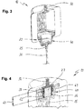
- the status of the disconnector device 10 known from fig. 2 is shown in a state after operation of the disconnector device 10.
- the movable member 40 has been propelled by the developing gas pressure from the operating disconnector unit 25 together with the second terminal 35 towards the end 45 of the cavity 20.
- the first terminal 30 and the second terminal 35 are displaced from one another by a predeterminable insulating distance such that the electric conduction path between the first terminal 30 and the second terminal 35 is interrupted. Since the disconnector cartridge 26 has vanished, i.e. its structure was dissolved during the operation of the disconnector unit 25.
- the movable member 40 is located at the end 45 of cavity 20 and secure against any movement back to its initial position by the stop shoulder 22 of the protrusion 48. At the same time, the cavity 20 is effectively closed, with the exception of ventilation openings described further below. Thus, hot solid particles from the operating disconnector unit 25 are kept inside the cavity 20, and thus inside the housing 15.
- the housing is designed to achieve different functions: It defines together with the movable member 40 a confined variable volume of the cavity 20, that makes use of the blasting energy of the disconnector cartridge 26 to provide a pressure build-up, which is suitable to cause a parting speed of the first terminal 30 (fixed) and the second terminal 35 (connected to the propelled movable member and to ground potential 37) which is high enough to interrupt the current in the temporary overvoltage situation. Further, by the retaining of the movable member 40, a subsequent restrike after current zero is avoided. The insulation distance between the first terminal 30 and the second terminal 35 is sufficient to prevent an undesired re-arcing in case of a temporary overvoltage.
- the housing 15 has an opening 55 (see Fig. 2 ) located in the end 45 of the cavity 20.
- the movable member 40 and the opening 55 are adjusted to each other, such that after operation of the disconnector unit 25, a part of the movable member 40 fits into the opening 55 and thereby closes it.
- this is shown in fig. 2 and fig. 3 , while in the latter, the closed status after operation of the disconnector unit is shown.
- the part of the movable member 40 protruding through the opening 55 is visible from an outside of the housing 15 by a human observer.
- at least the part of the movable member 40 protruding through the opening 55 see fig.
- the opening 55 and the tubular section 42 may have a signal color, for example red or orange.
- the inner housing 15 has a plurality of ventilation openings 65 connecting the cavity 20 to the gap 17 outside the inner housing 15.
- the outer housing 16 has a plurality of further ventilation openings 66 connecting the gap 17 to an outside of the disconnector device 10.
- the ventilation openings 65 and the further ventilation openings 66 are displaced against one another such that a labyrinth 67 for the gases from the operating disconnector cartridge 26 is formed on their way out of the cavity 20, i.e. on their gas escape path 68.
- Fig. 5 is a simplified cross-sectional view through the housing unit 14 without the movable member 40 such that the opening 55 at the bottom of the housing unit 14 is visible.
- the ventilation openings 65 as well as the further ventilation openings 66 are slots having a slot-like shape extending in the direction of the longitudinal axis 19.
- the effect of the ventilation openings 65 is that the decrease of the gas pressure inside cavity 20 is promoted, while the movable member 40 moves towards the end 45 of the cavity 20.
- the movable member 40 has the shape of a cup with a protruding rim 50, having a hexagonal cross section at least at a portion with the largest diameter.
- Fig. 2 discloses that the disconnector device 10 encompasses the disconnector cartridge 26 at least partly. In this manner, the volume between the first terminal 30 and the movable member 40 is designed such that is forms a significant part taken up by the disconnector cartridge 26. This ensures a very high acceleration when the movable member 40.
- the first terminal 30 of the disconnector unit 25 is in some embodiments mounted to the housing 15 by screwing. That is, where the first terminal extends through the housing unit 14, the housing has an inner thread fitting an outer thread on the first terminal 30.
- Fig. 6 shows a temporary overvoltage protection assembly 11 with a disconnector device 10 that is electrically connected to a high voltage surge arrester 140.
- a first terminal 141 of the surge arrester 140 is electrically connectable to an electrical grid line 139.
- the first terminal 30 of the disconnector device 10 is electrically connected to a second terminal 142 of the high voltage surge arrester 140.
- the second terminal 35 of the disconnector device 10 is electrically connectable to ground potential 37 via a flexible ground cable 36.
- a bracket 143 is provided for mechanically fastening the temporary overvoltage protection assembly 11 to a structure such as a mast or pylon in an electrically insulated manner.
- the temporary overvoltage protection assembly 11 work as follows. When the surge arrester 140 enters its conductive state once a predetermined threshold current is exceeded due to an over voltage fault, the resulting high current flows from the electrical grid line 139 through the surge arrester 140 and the disconnector device 10 towards ground. While it flows through disconnector unit 25 in an initial state of the temporary overvoltage, the disconnector cartridge 26 operates after a predetermined time span that is determined by the current flowing and the characteristics of the disconnector cartridge 26. Next, the disconnector unit 25 operates, while producing a volume of hot gas as well as some solid residues that are typically very hot. The resulting fast rise of the pressure in the cavity 20 propels the movable member 40 towards the end 45 of the cavity.
- the embodiment of the disconnector device 10 shown in fig. 4 varies to the one shown in fig. 2 only in one detail. Hence, fig.4 and the description relating thereto focus exclusively to the detail. Thus, identical or at least functionally identical elements of that embodiment are provided with the same reference characters as the embodiment shown in fig. 2 .
- the first terminal 30 has a cup-shaped portion 61 for laterally encompassing the disconnector cartridge 26 in the direction of the longitudinal axis 19 at least in part.
- the disconnector cartridge 26 is again a charge comprising a varistor element 27 formed by a SiC-block and a blank cartridge that is designed such that it superheats and operate by igniting the blank cartridge by temperature before the dedicated surge arrester 140 forming a further varistor superheats such that it reaches its thermal limit and fails.
- the SiC-block is provided in a tubular insulation element 28 made of an electrical insulating material. The tubular insulation element 28 prevents that a current can creep along the lateral surface of the SiC-block 27 from the first terminal 30 to the second terminal 35.
- the spark gap 62 created by that measure is shorter in dimension than a thickness 63 of the disconnector cartridge 26 extending in the direction of the longitudinal axis (19).
- the dimension of the cup-shaped portion 61 for laterally encompassing the disconnector cartridge 26 in the direction of the longitudinal axis 19 can be varied according to the demands on the spark gap 62 in order to short circuit the disconnector during impulse voltages in the electrical grid line 139 where the disconnector unit 25 shall not operate. It is not desired that the disconnector unit 25 operates at every temporary overvoltage in the electrical grid line but only in temporary overvoltage lasting longer than a predeterminable time.
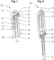
- a second embodiment of a disconnector device 100 is shown and described with respect to fig. 7 and fig. 8 .
- Said second embodiment of a disconnector device 100 has basically the same working principle as the one described with respect to figures 2 and 3 .
- Fig. 7 shows the disconnector device 100 in its pristine state, i.e. before operation whereas fig. 8 shows it in its state after operation.
- the display of the outer housing 16 is there and arranged in the same fashion as shown in fig. 5 but is not displayed in figures 7 and 8 to keep the figures as simple as possible.
- the cavity 20 in the inner housing 15 as well as the movable member 41 have a circular cross section.
- the rim 50 of the movable member 41 is longer in the direction of the longitudinal axis for easing the travel from the first position to an end position.
- the movable member 41 is again cup shaped and encompasses the disconnector cartridge 26 laterally and axially towards the lower end 45 of the cavity 20.
- the tubular section 42 has a smaller diameter than the cup-shaped portion of the movable member 41.
- the diameter of the tubular section 42 and the diameter of the opening 55 are adjusted to each other such that the tubular section 42 can move freely in the opening 55. Again, there is only a small circumferential gap between the opening 55 and the tubular section 42, for example having a size from 0.1 mm to 5 mm, more typically from 0.5 mm to 3.5 mm.
- the cylindrical wall of the inner housing 15 has no ventilation openings 65.
- the gas escape path 68 leads through a first annular gap between the rim 50 of the movable member 41 and through a second annular gap between the tubular section 42 of the movable member 41 and the opening 55 of the housing unit 14.
- hot particles from the operating disconnector unit 25 are again kept inside the cavity 20, and thus inside the housing unit 14 as the first annular gap and the second annular gap form the labyrinth 67.
Landscapes
- Gas-Insulated Switchgears (AREA)
- Emergency Protection Circuit Devices (AREA)
- Arc-Extinguishing Devices That Are Switches (AREA)
Priority Applications (1)
| Application Number | Priority Date | Filing Date | Title |
|---|---|---|---|
| EP21154983.7A EP3840140A1 (fr) | 2016-09-13 | 2017-08-30 | Protection d'un limiteur de surtension avec une meilleure protection contre les défaillances de la surcharge thermique en cas de surtension temporaire ligne dans une grille électrique |
Applications Claiming Priority (1)
| Application Number | Priority Date | Filing Date | Title |
|---|---|---|---|
| LU93206A LU93206B1 (en) | 2016-09-13 | 2016-09-13 | Protection of a surge arrester with a better protection against failure from thermal overload in case of a temporary overvoltage in an electrical grid line |
Related Child Applications (2)
| Application Number | Title | Priority Date | Filing Date |
|---|---|---|---|
| EP21154983.7A Division-Into EP3840140A1 (fr) | 2016-09-13 | 2017-08-30 | Protection d'un limiteur de surtension avec une meilleure protection contre les défaillances de la surcharge thermique en cas de surtension temporaire ligne dans une grille électrique |
| EP21154983.7A Division EP3840140A1 (fr) | 2016-09-13 | 2017-08-30 | Protection d'un limiteur de surtension avec une meilleure protection contre les défaillances de la surcharge thermique en cas de surtension temporaire ligne dans une grille électrique |
Publications (3)
| Publication Number | Publication Date |
|---|---|
| EP3293839A2 true EP3293839A2 (fr) | 2018-03-14 |
| EP3293839A3 EP3293839A3 (fr) | 2018-04-11 |
| EP3293839B1 EP3293839B1 (fr) | 2024-05-22 |
Family
ID=57178451
Family Applications (2)
| Application Number | Title | Priority Date | Filing Date |
|---|---|---|---|
| EP21154983.7A Pending EP3840140A1 (fr) | 2016-09-13 | 2017-08-30 | Protection d'un limiteur de surtension avec une meilleure protection contre les défaillances de la surcharge thermique en cas de surtension temporaire ligne dans une grille électrique |
| EP17188606.2A Active EP3293839B1 (fr) | 2016-09-13 | 2017-08-30 | Protection d'un limiteur de surtension avec une meilleure protection contre les défaillances de la surcharge thermique en cas de surtension temporaire ligne dans une grille électrique |
Family Applications Before (1)
| Application Number | Title | Priority Date | Filing Date |
|---|---|---|---|
| EP21154983.7A Pending EP3840140A1 (fr) | 2016-09-13 | 2017-08-30 | Protection d'un limiteur de surtension avec une meilleure protection contre les défaillances de la surcharge thermique en cas de surtension temporaire ligne dans une grille électrique |
Country Status (4)
| Country | Link |
|---|---|
| US (2) | US11322934B2 (fr) |
| EP (2) | EP3840140A1 (fr) |
| AU (1) | AU2017219085B2 (fr) |
| LU (1) | LU93206B1 (fr) |
Cited By (3)
| Publication number | Priority date | Publication date | Assignee | Title |
|---|---|---|---|---|
| EP3629430A1 (fr) * | 2018-09-28 | 2020-04-01 | ABB Schweiz AG | Limiteur de ligne à entrefer extérieur |
| EP3963684A4 (fr) * | 2019-04-29 | 2023-01-18 | Hubbell Incorporated | Dispositif de déconnexion et assemblage de protection contre les surtensions équipé dudit dispositif |
| EP4078628A4 (fr) * | 2019-12-20 | 2024-01-10 | Hubbell Inc | Parasurtenseur isolé doté de dispositif de déconnexion |
Families Citing this family (4)
| Publication number | Priority date | Publication date | Assignee | Title |
|---|---|---|---|---|
| CN109256760B (zh) * | 2018-09-28 | 2022-05-20 | 李建国 | 一种超长距蜂巢式防雷保护方法 |
| CN111832961B (zh) * | 2020-07-23 | 2023-04-28 | 河南省计量科学研究院 | 电网的高压冲击测量装置及方法 |
| US20220077673A1 (en) | 2020-09-09 | 2022-03-10 | Abb Power Grids Switzerland Ag | Chargeless interrupter device for surge arrester |
| AU2021401413A1 (en) * | 2020-12-18 | 2023-07-06 | Hubbell Incorporated | Spark gap assembly for overvoltage protection and surge arrester |
Family Cites Families (36)
| Publication number | Priority date | Publication date | Assignee | Title |
|---|---|---|---|---|
| US2504438A (en) * | 1944-07-19 | 1950-04-18 | Electric Service Mfg Company | Circuit interrupter |
| GB628155A (en) * | 1947-03-13 | 1949-08-23 | E M P Electric Ltd | Improvements in and relating to lighting arresters |
| GB782902A (en) * | 1954-08-09 | 1957-09-18 | E M P Electric Ltd | Improvements in lightning arresters for electric power lines |
| US3239631A (en) * | 1964-09-29 | 1966-03-08 | Porter Co Inc H K | Lightning arrester separator |
| CH483732A (de) * | 1968-06-12 | 1969-12-31 | Bbc Brown Boveri & Cie | Uberspannungsableiter |
| US3755715A (en) * | 1972-10-11 | 1973-08-28 | Reliable Electric Co | Line protector having arrester and fail-safe circuit bypassing the arrester |
| US4204238A (en) * | 1978-02-06 | 1980-05-20 | General Electric Company | Surge voltage lightning arresters |
| US4577148A (en) * | 1982-12-17 | 1986-03-18 | Westinghouse Electric Corp. | Surge arrester equipped for monitoring functions and method of use |
| US4710847A (en) * | 1986-06-09 | 1987-12-01 | Juri Kortschinski | Current-limiting surge arrester disconnector |
| US4930039A (en) * | 1989-04-18 | 1990-05-29 | Cooper Industries, Inc. | Fail-safe surge arrester |
| CA2038720A1 (fr) | 1990-04-02 | 1991-10-03 | Takeshi Kawamura | Parafoudre |
| US5057810A (en) * | 1991-02-14 | 1991-10-15 | Hubbell Incorporated | Arrester isolator-disconnector |
| US5523916A (en) * | 1994-06-03 | 1996-06-04 | Reliance Comm/Tec Corporation | Surge arrester with thermal overload protection |
| DE19506307A1 (de) * | 1995-02-23 | 1996-08-29 | Abb Management Ag | Vorrichtung zur Anzeige eines fehlerhaften Zustands eines elektrischen Apparates, insbesondere eines Überspannungsableiters |
| GB9522875D0 (en) | 1995-11-08 | 1996-01-10 | Raychem Gmbh | Surge arrester |
| DE19637984A1 (de) * | 1996-09-18 | 1998-03-19 | Asea Brown Boveri | Elektrischer Apparat, insbesondere Überspannungsableiter und System zur Anzeige des Zustands dieses Apparats in einer zentralen Auswertevorrichtung |
| US5952910A (en) | 1997-12-04 | 1999-09-14 | Hubbell Incorporated | Isolator device for arrester |
| DE10025685A1 (de) * | 2000-05-19 | 2001-11-29 | Siemens Ag | Trennschalt-Vorrichtung für einen Hochspannungs-Überspannungsableiter |
| US6876289B2 (en) * | 2003-05-29 | 2005-04-05 | Hubbell Incorporated | Arrester disconnector assembly having a capacitor |
| DE502004004354D1 (de) | 2004-02-19 | 2007-08-30 | Abb Technology Ag | Störlichtbogengeschütztes elektrisches Bauteil |
| DE102005015401B4 (de) * | 2005-01-10 | 2014-03-20 | Dehn + Söhne Gmbh + Co. Kg | Überspannungsableiter mit zwei divergierenden Elektroden und einer zwischen den Elektroden wirkenden Funkenstrecke |
| US7433169B2 (en) * | 2005-12-15 | 2008-10-07 | Raycap Corporation | Overvoltage protection devices including wafer of varistor material |
| US20080068122A1 (en) * | 2006-09-15 | 2008-03-20 | Hubbell Incorporated | Arrester Disconnector Assembly Minimizing Explosive Separation |
| DE102006051166A1 (de) * | 2006-10-25 | 2008-04-30 | Siemens Ag | Abtrennanordnung und Verfahren zum Betätigen einer Abtrennanordnung |
| CN101521065B (zh) | 2008-02-29 | 2012-05-30 | 深圳市安普富诚科技有限公司 | 防爆自动脱离型避雷器 |
| DE102009004317A1 (de) * | 2008-08-22 | 2010-02-25 | Dehn + Söhne Gmbh + Co. Kg | Schnelle Abtrennvorrichtung |
| CN201498291U (zh) * | 2009-07-23 | 2010-06-02 | 江苏新民电力设备有限公司 | 可拆卸式避雷器 |
| US20110018704A1 (en) * | 2009-07-24 | 2011-01-27 | Burrows Zachary M | System, Device and Method for Providing Power Line Communications |
| CN201584650U (zh) * | 2009-12-14 | 2010-09-15 | 西安安捷迅电气有限公司 | 一种多级放电避雷器用脱离器 |
| US8711538B2 (en) * | 2010-10-06 | 2014-04-29 | Jonathan Jay Woodworth | Externally gapped line arrester |
| US8993916B2 (en) * | 2012-12-07 | 2015-03-31 | General Electric Company | Variable venting and damping arc mitigation assemblies and methods of assembly |
| DE102014008366B3 (de) | 2014-06-04 | 2015-10-22 | Dehn + Söhne Gmbh + Co. Kg | Vorrichtung zum thermischen Auslösen oder Abtrennen eines Überspannungsschutzgerätes |
| DE102014215280B3 (de) * | 2014-08-04 | 2015-09-24 | Phoenix Contact Gmbh & Co. Kg | Kombiniertes Überspannungsschutzgerät mit einer integrierten Funkenstrecke |
| WO2017148544A1 (fr) * | 2016-02-29 | 2017-09-08 | Abb Schweiz Ag | Dispositif sectionneur pour parasurtenseur et ensemble de protection comprenant un parasurtenseur connecté à un tel dispositif sectionneur |
| CA3034870C (fr) * | 2016-09-13 | 2023-07-04 | Abb Schweiz Ag | Dispositif sectionneur pour parasurtenseur et ensemble de protection comprenant un parasurtenseur connecte a un tel dispositif sectionneur |
| WO2020223348A1 (fr) * | 2019-04-29 | 2020-11-05 | Hubbell Incorporated | Dispositif de déconnexion et assemblage de protection contre les surtensions équipé dudit dispositif |
-
2016
- 2016-09-13 LU LU93206A patent/LU93206B1/de active IP Right Grant
-
2017
- 2017-08-25 AU AU2017219085A patent/AU2017219085B2/en active Active
- 2017-08-30 EP EP21154983.7A patent/EP3840140A1/fr active Pending
- 2017-08-30 EP EP17188606.2A patent/EP3293839B1/fr active Active
- 2017-09-13 US US15/703,524 patent/US11322934B2/en active Active
-
2022
- 2022-04-20 US US17/724,871 patent/US11682899B2/en active Active
Cited By (8)
| Publication number | Priority date | Publication date | Assignee | Title |
|---|---|---|---|---|
| EP3629430A1 (fr) * | 2018-09-28 | 2020-04-01 | ABB Schweiz AG | Limiteur de ligne à entrefer extérieur |
| WO2020064308A1 (fr) * | 2018-09-28 | 2020-04-02 | Abb Power Grids Switzerland Ag | Dispositif d'arrêt de ligne à entrefer externe |
| CN112789774A (zh) * | 2018-09-28 | 2021-05-11 | Abb电网瑞士股份公司 | 外部间隙线路避雷器 |
| RU2767757C1 (ru) * | 2018-09-28 | 2022-03-21 | Хитачи Энерджи Свитцерланд Аг | Линейный разрядник с внешним искровым промежутком |
| US11322913B2 (en) * | 2018-09-28 | 2022-05-03 | Hitachi Energy Switzerland Ag | Externally gapped line arrester |
| CN112789774B (zh) * | 2018-09-28 | 2022-05-31 | 日立能源瑞士股份公司 | 外部间隙线路避雷器 |
| EP3963684A4 (fr) * | 2019-04-29 | 2023-01-18 | Hubbell Incorporated | Dispositif de déconnexion et assemblage de protection contre les surtensions équipé dudit dispositif |
| EP4078628A4 (fr) * | 2019-12-20 | 2024-01-10 | Hubbell Inc | Parasurtenseur isolé doté de dispositif de déconnexion |
Also Published As
| Publication number | Publication date |
|---|---|
| EP3293839A3 (fr) | 2018-04-11 |
| AU2017219085A1 (en) | 2018-03-29 |
| EP3293839B1 (fr) | 2024-05-22 |
| LU93206B1 (en) | 2018-03-16 |
| AU2017219085B2 (en) | 2022-03-17 |
| US20180076617A1 (en) | 2018-03-15 |
| US11322934B2 (en) | 2022-05-03 |
| US20220247170A1 (en) | 2022-08-04 |
| US11682899B2 (en) | 2023-06-20 |
| EP3840140A1 (fr) | 2021-06-23 |
Similar Documents
| Publication | Publication Date | Title |
|---|---|---|
| US11682899B2 (en) | Protection of a surge arrester with a better protection against failure from thermal overload in case of a temporary overvoltage in an electrical grid line | |
| US10109399B2 (en) | Disconnector device for a surge arrester and a protection assembly comprising a surge arrester connected to such a disconnector device | |
| US10454251B2 (en) | Disconnector device for surge arrester and a protection assembly comprising a surge arrester connected to such a disconnector device | |
| US11721457B2 (en) | Deadfront arrester with disconnector device | |
| US11942777B2 (en) | Disconnector device and overvoltage protection assembly including the same |
Legal Events
| Date | Code | Title | Description |
|---|---|---|---|
| PUAI | Public reference made under article 153(3) epc to a published international application that has entered the european phase |
Free format text: ORIGINAL CODE: 0009012 |
|
| STAA | Information on the status of an ep patent application or granted ep patent |
Free format text: STATUS: THE APPLICATION HAS BEEN PUBLISHED |
|
| PUAL | Search report despatched |
Free format text: ORIGINAL CODE: 0009013 |
|
| AK | Designated contracting states |
Kind code of ref document: A2 Designated state(s): AL AT BE BG CH CY CZ DE DK EE ES FI FR GB GR HR HU IE IS IT LI LT LU LV MC MK MT NL NO PL PT RO RS SE SI SK SM TR |
|
| AX | Request for extension of the european patent |
Extension state: BA ME |
|
| RIN1 | Information on inventor provided before grant (corrected) |
Inventor name: BOESE, RONALD Inventor name: GARIBOLDI, NICOLA Inventor name: ANTELO, JOEL Inventor name: MUGWYLER, REMO |
|
| AK | Designated contracting states |
Kind code of ref document: A3 Designated state(s): AL AT BE BG CH CY CZ DE DK EE ES FI FR GB GR HR HU IE IS IT LI LT LU LV MC MK MT NL NO PL PT RO RS SE SI SK SM TR |
|
| AX | Request for extension of the european patent |
Extension state: BA ME |
|
| RIC1 | Information provided on ipc code assigned before grant |
Ipc: H01T 1/14 20060101AFI20180306BHEP Ipc: H01H 39/00 20060101ALI20180306BHEP |
|
| TPAC | Observations filed by third parties |
Free format text: ORIGINAL CODE: EPIDOSNTIPA |
|
| STAA | Information on the status of an ep patent application or granted ep patent |
Free format text: STATUS: REQUEST FOR EXAMINATION WAS MADE |
|
| 17P | Request for examination filed |
Effective date: 20180928 |
|
| RBV | Designated contracting states (corrected) |
Designated state(s): AL AT BE BG CH CY CZ DE DK EE ES FI FR GB GR HR HU IE IS IT LI LT LU LV MC MK MT NL NO PL PT RO RS SE SI SK SM TR |
|
| STAA | Information on the status of an ep patent application or granted ep patent |
Free format text: STATUS: EXAMINATION IS IN PROGRESS |
|
| 17Q | First examination report despatched |
Effective date: 20181119 |
|
| GRAP | Despatch of communication of intention to grant a patent |
Free format text: ORIGINAL CODE: EPIDOSNIGR1 |
|
| STAA | Information on the status of an ep patent application or granted ep patent |
Free format text: STATUS: GRANT OF PATENT IS INTENDED |
|
| INTG | Intention to grant announced |
Effective date: 20200526 |
|
| RAP1 | Party data changed (applicant data changed or rights of an application transferred) |
Owner name: ABB POWER GRIDS SWITZERLAND AG |
|
| RIN1 | Information on inventor provided before grant (corrected) |
Inventor name: MUGWYLER, REMO Inventor name: ANTELO, JOEL Inventor name: BOESE, RONALD Inventor name: GARIBOLDI, NICOLA |
|
| GRAJ | Information related to disapproval of communication of intention to grant by the applicant or resumption of examination proceedings by the epo deleted |
Free format text: ORIGINAL CODE: EPIDOSDIGR1 |
|
| STAA | Information on the status of an ep patent application or granted ep patent |
Free format text: STATUS: EXAMINATION IS IN PROGRESS |
|
| STAA | Information on the status of an ep patent application or granted ep patent |
Free format text: STATUS: EXAMINATION IS IN PROGRESS |
|
| INTC | Intention to grant announced (deleted) | ||
| STAA | Information on the status of an ep patent application or granted ep patent |
Free format text: STATUS: EXAMINATION IS IN PROGRESS |
|
| RAP3 | Party data changed (applicant data changed or rights of an application transferred) |
Owner name: HITACHI ENERGY SWITZERLAND AG |
|
| P01 | Opt-out of the competence of the unified patent court (upc) registered |
Effective date: 20230527 |
|
| GRAP | Despatch of communication of intention to grant a patent |
Free format text: ORIGINAL CODE: EPIDOSNIGR1 |
|
| STAA | Information on the status of an ep patent application or granted ep patent |
Free format text: STATUS: GRANT OF PATENT IS INTENDED |
|
| RAP1 | Party data changed (applicant data changed or rights of an application transferred) |
Owner name: HITACHI ENERGY LTD |
|
| INTG | Intention to grant announced |
Effective date: 20231207 |
|
| RIN1 | Information on inventor provided before grant (corrected) |
Inventor name: GARIBOLDI, NICOLA Inventor name: MUGWYLER, REMO Inventor name: ANTELO, JOEL Inventor name: BOESE, RONALD |
|
| GRAJ | Information related to disapproval of communication of intention to grant by the applicant or resumption of examination proceedings by the epo deleted |
Free format text: ORIGINAL CODE: EPIDOSDIGR1 |
|
| STAA | Information on the status of an ep patent application or granted ep patent |
Free format text: STATUS: EXAMINATION IS IN PROGRESS |
|
| INTC | Intention to grant announced (deleted) | ||
| GRAP | Despatch of communication of intention to grant a patent |
Free format text: ORIGINAL CODE: EPIDOSNIGR1 |
|
| STAA | Information on the status of an ep patent application or granted ep patent |
Free format text: STATUS: GRANT OF PATENT IS INTENDED |
|
| GRAS | Grant fee paid |
Free format text: ORIGINAL CODE: EPIDOSNIGR3 |
|
| GRAA | (expected) grant |
Free format text: ORIGINAL CODE: 0009210 |
|
| STAA | Information on the status of an ep patent application or granted ep patent |
Free format text: STATUS: THE PATENT HAS BEEN GRANTED |
|
| INTG | Intention to grant announced |
Effective date: 20240402 |
|
| AK | Designated contracting states |
Kind code of ref document: B1 Designated state(s): AL AT BE BG CH CY CZ DE DK EE ES FI FR GB GR HR HU IE IS IT LI LT LU LV MC MK MT NL NO PL PT RO RS SE SI SK SM TR |
|
| REG | Reference to a national code |
Ref country code: GB Ref legal event code: FG4D |