EP3293424B1 - Sealing apparatus - Google Patents
Sealing apparatus Download PDFInfo
- Publication number
- EP3293424B1 EP3293424B1 EP16792625.2A EP16792625A EP3293424B1 EP 3293424 B1 EP3293424 B1 EP 3293424B1 EP 16792625 A EP16792625 A EP 16792625A EP 3293424 B1 EP3293424 B1 EP 3293424B1
- Authority
- EP
- European Patent Office
- Prior art keywords
- sealing apparatus
- grease
- inclined surface
- seal
- axis
- Prior art date
- Legal status (The legal status is an assumption and is not a legal conclusion. Google has not performed a legal analysis and makes no representation as to the accuracy of the status listed.)
- Active
Links
- 238000007789 sealing Methods 0.000 title claims description 66
- 239000004519 grease Substances 0.000 claims description 54
- 239000012530 fluid Substances 0.000 claims description 35
- 239000003921 oil Substances 0.000 claims description 25
- 239000000344 soap Substances 0.000 claims description 23
- 239000002480 mineral oil Substances 0.000 claims description 21
- 239000004215 Carbon black (E152) Substances 0.000 claims description 17
- 229930195733 hydrocarbon Natural products 0.000 claims description 17
- 150000002430 hydrocarbons Chemical class 0.000 claims description 17
- 235000010446 mineral oil Nutrition 0.000 claims description 16
- 239000002199 base oil Substances 0.000 claims description 13
- 239000000428 dust Substances 0.000 claims description 13
- 229910052751 metal Inorganic materials 0.000 claims description 11
- 239000002184 metal Substances 0.000 claims description 11
- 239000002562 thickening agent Substances 0.000 claims description 10
- 150000004696 coordination complex Chemical class 0.000 claims description 4
- 229920013639 polyalphaolefin Polymers 0.000 claims description 4
- 238000002485 combustion reaction Methods 0.000 claims description 3
- 230000002093 peripheral effect Effects 0.000 description 25
- 230000003014 reinforcing effect Effects 0.000 description 16
- 230000000052 comparative effect Effects 0.000 description 8
- -1 fatty acid amines Chemical class 0.000 description 8
- 239000000314 lubricant Substances 0.000 description 8
- 235000014113 dietary fatty acids Nutrition 0.000 description 7
- 239000000194 fatty acid Substances 0.000 description 7
- 229930195729 fatty acid Natural products 0.000 description 7
- 238000010586 diagram Methods 0.000 description 6
- 239000000463 material Substances 0.000 description 6
- 150000003839 salts Chemical class 0.000 description 6
- 239000003963 antioxidant agent Substances 0.000 description 5
- 229910052788 barium Inorganic materials 0.000 description 5
- DSAJWYNOEDNPEQ-UHFFFAOYSA-N barium atom Chemical compound [Ba] DSAJWYNOEDNPEQ-UHFFFAOYSA-N 0.000 description 5
- YCKRFDGAMUMZLT-UHFFFAOYSA-N Fluorine atom Chemical compound [F] YCKRFDGAMUMZLT-UHFFFAOYSA-N 0.000 description 4
- 239000002253 acid Substances 0.000 description 4
- 239000003795 chemical substances by application Substances 0.000 description 4
- 230000000694 effects Effects 0.000 description 4
- 150000004665 fatty acids Chemical class 0.000 description 4
- 239000011737 fluorine Substances 0.000 description 4
- 229910052731 fluorine Inorganic materials 0.000 description 4
- 239000003112 inhibitor Substances 0.000 description 4
- WHXSMMKQMYFTQS-UHFFFAOYSA-N Lithium Chemical compound [Li] WHXSMMKQMYFTQS-UHFFFAOYSA-N 0.000 description 3
- 229920000459 Nitrile rubber Polymers 0.000 description 3
- 229920000800 acrylic rubber Polymers 0.000 description 3
- 238000004132 cross linking Methods 0.000 description 3
- 229920001971 elastomer Polymers 0.000 description 3
- 229910052744 lithium Inorganic materials 0.000 description 3
- 238000005461 lubrication Methods 0.000 description 3
- 229920000058 polyacrylate Polymers 0.000 description 3
- 239000005060 rubber Substances 0.000 description 3
- OYPRJOBELJOOCE-UHFFFAOYSA-N Calcium Chemical compound [Ca] OYPRJOBELJOOCE-UHFFFAOYSA-N 0.000 description 2
- XQVWYOYUZDUNRW-UHFFFAOYSA-N N-Phenyl-1-naphthylamine Chemical class C=1C=CC2=CC=CC=C2C=1NC1=CC=CC=C1 XQVWYOYUZDUNRW-UHFFFAOYSA-N 0.000 description 2
- NBIIXXVUZAFLBC-UHFFFAOYSA-N Phosphoric acid Chemical compound OP(O)(O)=O NBIIXXVUZAFLBC-UHFFFAOYSA-N 0.000 description 2
- NINIDFKCEFEMDL-UHFFFAOYSA-N Sulfur Chemical compound [S] NINIDFKCEFEMDL-UHFFFAOYSA-N 0.000 description 2
- 230000002411 adverse Effects 0.000 description 2
- 239000011575 calcium Substances 0.000 description 2
- 229910052791 calcium Inorganic materials 0.000 description 2
- 150000001875 compounds Chemical class 0.000 description 2
- 238000005260 corrosion Methods 0.000 description 2
- 230000007797 corrosion Effects 0.000 description 2
- 230000007423 decrease Effects 0.000 description 2
- 150000002148 esters Chemical class 0.000 description 2
- 238000011156 evaluation Methods 0.000 description 2
- 125000004435 hydrogen atom Chemical group [H]* 0.000 description 2
- JEIPFZHSYJVQDO-UHFFFAOYSA-N iron(III) oxide Inorganic materials O=[Fe]O[Fe]=O JEIPFZHSYJVQDO-UHFFFAOYSA-N 0.000 description 2
- 239000010687 lubricating oil Substances 0.000 description 2
- 230000007246 mechanism Effects 0.000 description 2
- 238000000034 method Methods 0.000 description 2
- 239000000203 mixture Substances 0.000 description 2
- 230000035515 penetration Effects 0.000 description 2
- 150000002990 phenothiazines Chemical class 0.000 description 2
- 239000004810 polytetrafluoroethylene Substances 0.000 description 2
- 229920001343 polytetrafluoroethylene Polymers 0.000 description 2
- 238000005086 pumping Methods 0.000 description 2
- 239000007787 solid Substances 0.000 description 2
- 239000011593 sulfur Substances 0.000 description 2
- 229910052717 sulfur Inorganic materials 0.000 description 2
- 230000001629 suppression Effects 0.000 description 2
- MDWVSAYEQPLWMX-UHFFFAOYSA-N 4,4'-Methylenebis(2,6-di-tert-butylphenol) Chemical compound CC(C)(C)C1=C(O)C(C(C)(C)C)=CC(CC=2C=C(C(O)=C(C=2)C(C)(C)C)C(C)(C)C)=C1 MDWVSAYEQPLWMX-UHFFFAOYSA-N 0.000 description 1
- 229910052582 BN Inorganic materials 0.000 description 1
- PZNSFCLAULLKQX-UHFFFAOYSA-N Boron nitride Chemical compound N#B PZNSFCLAULLKQX-UHFFFAOYSA-N 0.000 description 1
- NLZUEZXRPGMBCV-UHFFFAOYSA-N Butylhydroxytoluene Chemical compound CC1=CC(C(C)(C)C)=C(O)C(C(C)(C)C)=C1 NLZUEZXRPGMBCV-UHFFFAOYSA-N 0.000 description 1
- KXDHJXZQYSOELW-UHFFFAOYSA-N Carbamic acid Chemical compound NC(O)=O KXDHJXZQYSOELW-UHFFFAOYSA-N 0.000 description 1
- OKTJSMMVPCPJKN-UHFFFAOYSA-N Carbon Chemical compound [C] OKTJSMMVPCPJKN-UHFFFAOYSA-N 0.000 description 1
- 229920000089 Cyclic olefin copolymer Polymers 0.000 description 1
- DGAQECJNVWCQMB-PUAWFVPOSA-M Ilexoside XXIX Chemical compound C[C@@H]1CC[C@@]2(CC[C@@]3(C(=CC[C@H]4[C@]3(CC[C@@H]5[C@@]4(CC[C@@H](C5(C)C)OS(=O)(=O)[O-])C)C)[C@@H]2[C@]1(C)O)C)C(=O)O[C@H]6[C@@H]([C@H]([C@@H]([C@H](O6)CO)O)O)O.[Na+] DGAQECJNVWCQMB-PUAWFVPOSA-M 0.000 description 1
- OFOBLEOULBTSOW-UHFFFAOYSA-N Malonic acid Chemical compound OC(=O)CC(O)=O OFOBLEOULBTSOW-UHFFFAOYSA-N 0.000 description 1
- OAICVXFJPJFONN-UHFFFAOYSA-N Phosphorus Chemical compound [P] OAICVXFJPJFONN-UHFFFAOYSA-N 0.000 description 1
- 229920003171 Poly (ethylene oxide) Polymers 0.000 description 1
- ZLMJMSJWJFRBEC-UHFFFAOYSA-N Potassium Chemical compound [K] ZLMJMSJWJFRBEC-UHFFFAOYSA-N 0.000 description 1
- 239000000654 additive Substances 0.000 description 1
- 150000001298 alcohols Chemical class 0.000 description 1
- 125000001931 aliphatic group Chemical group 0.000 description 1
- 150000004996 alkyl benzenes Chemical class 0.000 description 1
- 150000005215 alkyl ethers Chemical class 0.000 description 1
- 229910052782 aluminium Inorganic materials 0.000 description 1
- XAGFODPZIPBFFR-UHFFFAOYSA-N aluminium Chemical compound [Al] XAGFODPZIPBFFR-UHFFFAOYSA-N 0.000 description 1
- 229910000147 aluminium phosphate Inorganic materials 0.000 description 1
- 150000001408 amides Chemical class 0.000 description 1
- 150000001412 amines Chemical class 0.000 description 1
- 150000001556 benzimidazoles Chemical class 0.000 description 1
- 125000006267 biphenyl group Chemical group 0.000 description 1
- 235000010354 butylated hydroxytoluene Nutrition 0.000 description 1
- 125000004432 carbon atom Chemical group C* 0.000 description 1
- 239000006229 carbon black Substances 0.000 description 1
- 239000010960 cold rolled steel Substances 0.000 description 1
- 238000001816 cooling Methods 0.000 description 1
- 150000002019 disulfides Chemical class 0.000 description 1
- 238000005242 forging Methods 0.000 description 1
- 239000012208 gear oil Substances 0.000 description 1
- 239000010439 graphite Substances 0.000 description 1
- 229910002804 graphite Inorganic materials 0.000 description 1
- 230000001050 lubricating effect Effects 0.000 description 1
- ZQKXQUJXLSSJCH-UHFFFAOYSA-N melamine cyanurate Chemical compound NC1=NC(N)=NC(N)=N1.O=C1NC(=O)NC(=O)N1 ZQKXQUJXLSSJCH-UHFFFAOYSA-N 0.000 description 1
- 238000002156 mixing Methods 0.000 description 1
- CWQXQMHSOZUFJS-UHFFFAOYSA-N molybdenum disulfide Chemical compound S=[Mo]=S CWQXQMHSOZUFJS-UHFFFAOYSA-N 0.000 description 1
- 229910052982 molybdenum disulfide Inorganic materials 0.000 description 1
- 239000012170 montan wax Substances 0.000 description 1
- 239000010705 motor oil Substances 0.000 description 1
- 238000000465 moulding Methods 0.000 description 1
- 239000010702 perfluoropolyether Substances 0.000 description 1
- 239000002530 phenolic antioxidant Substances 0.000 description 1
- 150000003014 phosphoric acid esters Chemical class 0.000 description 1
- OJMIONKXNSYLSR-UHFFFAOYSA-N phosphorous acid Chemical class OP(O)O OJMIONKXNSYLSR-UHFFFAOYSA-N 0.000 description 1
- 239000011574 phosphorus Substances 0.000 description 1
- 229910052698 phosphorus Inorganic materials 0.000 description 1
- 229920001083 polybutene Polymers 0.000 description 1
- 239000011591 potassium Substances 0.000 description 1
- 229910052700 potassium Inorganic materials 0.000 description 1
- 238000002360 preparation method Methods 0.000 description 1
- 229910000077 silane Inorganic materials 0.000 description 1
- 239000011734 sodium Substances 0.000 description 1
- 229910052708 sodium Inorganic materials 0.000 description 1
- 239000010935 stainless steel Substances 0.000 description 1
- 229910001220 stainless steel Inorganic materials 0.000 description 1
- 150000005846 sugar alcohols Polymers 0.000 description 1
- 150000004763 sulfides Chemical class 0.000 description 1
- 150000003464 sulfur compounds Chemical class 0.000 description 1
- 229920003051 synthetic elastomer Polymers 0.000 description 1
- 239000005061 synthetic rubber Substances 0.000 description 1
- 150000004867 thiadiazoles Chemical class 0.000 description 1
- 125000006617 triphenylamine group Chemical class 0.000 description 1
- 238000004073 vulcanization Methods 0.000 description 1
- 239000001993 wax Substances 0.000 description 1
- 239000004711 α-olefin Substances 0.000 description 1
Images

Classifications
-
- F—MECHANICAL ENGINEERING; LIGHTING; HEATING; WEAPONS; BLASTING
- F16—ENGINEERING ELEMENTS AND UNITS; GENERAL MEASURES FOR PRODUCING AND MAINTAINING EFFECTIVE FUNCTIONING OF MACHINES OR INSTALLATIONS; THERMAL INSULATION IN GENERAL
- F16J—PISTONS; CYLINDERS; SEALINGS
- F16J15/00—Sealings
- F16J15/16—Sealings between relatively-moving surfaces
- F16J15/32—Sealings between relatively-moving surfaces with elastic sealings, e.g. O-rings
- F16J15/3204—Sealings between relatively-moving surfaces with elastic sealings, e.g. O-rings with at least one lip
- F16J15/3232—Sealings between relatively-moving surfaces with elastic sealings, e.g. O-rings with at least one lip having two or more lips
-
- C—CHEMISTRY; METALLURGY
- C10—PETROLEUM, GAS OR COKE INDUSTRIES; TECHNICAL GASES CONTAINING CARBON MONOXIDE; FUELS; LUBRICANTS; PEAT
- C10M—LUBRICATING COMPOSITIONS; USE OF CHEMICAL SUBSTANCES EITHER ALONE OR AS LUBRICATING INGREDIENTS IN A LUBRICATING COMPOSITION
- C10M169/00—Lubricating compositions characterised by containing as components a mixture of at least two types of ingredient selected from base-materials, thickeners or additives, covered by the preceding groups, each of these compounds being essential
- C10M169/02—Mixtures of base-materials and thickeners
-
- F—MECHANICAL ENGINEERING; LIGHTING; HEATING; WEAPONS; BLASTING
- F02—COMBUSTION ENGINES; HOT-GAS OR COMBUSTION-PRODUCT ENGINE PLANTS
- F02F—CYLINDERS, PISTONS OR CASINGS, FOR COMBUSTION ENGINES; ARRANGEMENTS OF SEALINGS IN COMBUSTION ENGINES
- F02F11/00—Arrangements of sealings in combustion engines
-
- F—MECHANICAL ENGINEERING; LIGHTING; HEATING; WEAPONS; BLASTING
- F02—COMBUSTION ENGINES; HOT-GAS OR COMBUSTION-PRODUCT ENGINE PLANTS
- F02F—CYLINDERS, PISTONS OR CASINGS, FOR COMBUSTION ENGINES; ARRANGEMENTS OF SEALINGS IN COMBUSTION ENGINES
- F02F7/00—Casings, e.g. crankcases or frames
-
- F—MECHANICAL ENGINEERING; LIGHTING; HEATING; WEAPONS; BLASTING
- F16—ENGINEERING ELEMENTS AND UNITS; GENERAL MEASURES FOR PRODUCING AND MAINTAINING EFFECTIVE FUNCTIONING OF MACHINES OR INSTALLATIONS; THERMAL INSULATION IN GENERAL
- F16J—PISTONS; CYLINDERS; SEALINGS
- F16J15/00—Sealings
- F16J15/16—Sealings between relatively-moving surfaces
- F16J15/32—Sealings between relatively-moving surfaces with elastic sealings, e.g. O-rings
- F16J15/3204—Sealings between relatively-moving surfaces with elastic sealings, e.g. O-rings with at least one lip
-
- F—MECHANICAL ENGINEERING; LIGHTING; HEATING; WEAPONS; BLASTING
- F16—ENGINEERING ELEMENTS AND UNITS; GENERAL MEASURES FOR PRODUCING AND MAINTAINING EFFECTIVE FUNCTIONING OF MACHINES OR INSTALLATIONS; THERMAL INSULATION IN GENERAL
- F16J—PISTONS; CYLINDERS; SEALINGS
- F16J15/00—Sealings
- F16J15/16—Sealings between relatively-moving surfaces
- F16J15/32—Sealings between relatively-moving surfaces with elastic sealings, e.g. O-rings
- F16J15/324—Arrangements for lubrication or cooling of the sealing itself
-
- F—MECHANICAL ENGINEERING; LIGHTING; HEATING; WEAPONS; BLASTING
- F16—ENGINEERING ELEMENTS AND UNITS; GENERAL MEASURES FOR PRODUCING AND MAINTAINING EFFECTIVE FUNCTIONING OF MACHINES OR INSTALLATIONS; THERMAL INSULATION IN GENERAL
- F16J—PISTONS; CYLINDERS; SEALINGS
- F16J15/00—Sealings
- F16J15/16—Sealings between relatively-moving surfaces
- F16J15/32—Sealings between relatively-moving surfaces with elastic sealings, e.g. O-rings
- F16J15/3244—Sealings between relatively-moving surfaces with elastic sealings, e.g. O-rings with hydrodynamic pumping action
-
- C—CHEMISTRY; METALLURGY
- C10—PETROLEUM, GAS OR COKE INDUSTRIES; TECHNICAL GASES CONTAINING CARBON MONOXIDE; FUELS; LUBRICANTS; PEAT
- C10M—LUBRICATING COMPOSITIONS; USE OF CHEMICAL SUBSTANCES EITHER ALONE OR AS LUBRICATING INGREDIENTS IN A LUBRICATING COMPOSITION
- C10M2203/00—Organic non-macromolecular hydrocarbon compounds and hydrocarbon fractions as ingredients in lubricant compositions
- C10M2203/10—Petroleum or coal fractions, e.g. tars, solvents, bitumen
- C10M2203/102—Aliphatic fractions
- C10M2203/1025—Aliphatic fractions used as base material
-
- C—CHEMISTRY; METALLURGY
- C10—PETROLEUM, GAS OR COKE INDUSTRIES; TECHNICAL GASES CONTAINING CARBON MONOXIDE; FUELS; LUBRICANTS; PEAT
- C10M—LUBRICATING COMPOSITIONS; USE OF CHEMICAL SUBSTANCES EITHER ALONE OR AS LUBRICATING INGREDIENTS IN A LUBRICATING COMPOSITION
- C10M2205/00—Organic macromolecular hydrocarbon compounds or fractions, whether or not modified by oxidation as ingredients in lubricant compositions
- C10M2205/02—Organic macromolecular hydrocarbon compounds or fractions, whether or not modified by oxidation as ingredients in lubricant compositions containing acyclic monomers
- C10M2205/028—Organic macromolecular hydrocarbon compounds or fractions, whether or not modified by oxidation as ingredients in lubricant compositions containing acyclic monomers containing aliphatic monomers having more than four carbon atoms
- C10M2205/0285—Organic macromolecular hydrocarbon compounds or fractions, whether or not modified by oxidation as ingredients in lubricant compositions containing acyclic monomers containing aliphatic monomers having more than four carbon atoms used as base material
-
- C—CHEMISTRY; METALLURGY
- C10—PETROLEUM, GAS OR COKE INDUSTRIES; TECHNICAL GASES CONTAINING CARBON MONOXIDE; FUELS; LUBRICANTS; PEAT
- C10M—LUBRICATING COMPOSITIONS; USE OF CHEMICAL SUBSTANCES EITHER ALONE OR AS LUBRICATING INGREDIENTS IN A LUBRICATING COMPOSITION
- C10M2207/00—Organic non-macromolecular hydrocarbon compounds containing hydrogen, carbon and oxygen as ingredients in lubricant compositions
- C10M2207/10—Carboxylix acids; Neutral salts thereof
- C10M2207/12—Carboxylix acids; Neutral salts thereof having carboxyl groups bound to acyclic or cycloaliphatic carbon atoms
- C10M2207/125—Carboxylix acids; Neutral salts thereof having carboxyl groups bound to acyclic or cycloaliphatic carbon atoms having hydrocarbon chains of eight up to twenty-nine carbon atoms, i.e. fatty acids
- C10M2207/1256—Carboxylix acids; Neutral salts thereof having carboxyl groups bound to acyclic or cycloaliphatic carbon atoms having hydrocarbon chains of eight up to twenty-nine carbon atoms, i.e. fatty acids used as thickening agent
-
- C—CHEMISTRY; METALLURGY
- C10—PETROLEUM, GAS OR COKE INDUSTRIES; TECHNICAL GASES CONTAINING CARBON MONOXIDE; FUELS; LUBRICANTS; PEAT
- C10N—INDEXING SCHEME ASSOCIATED WITH SUBCLASS C10M RELATING TO LUBRICATING COMPOSITIONS
- C10N2020/00—Specified physical or chemical properties or characteristics, i.e. function, of component of lubricating compositions
- C10N2020/01—Physico-chemical properties
- C10N2020/02—Viscosity; Viscosity index
-
- C—CHEMISTRY; METALLURGY
- C10—PETROLEUM, GAS OR COKE INDUSTRIES; TECHNICAL GASES CONTAINING CARBON MONOXIDE; FUELS; LUBRICANTS; PEAT
- C10N—INDEXING SCHEME ASSOCIATED WITH SUBCLASS C10M RELATING TO LUBRICATING COMPOSITIONS
- C10N2030/00—Specified physical or chemical properties which is improved by the additive characterising the lubricating composition, e.g. multifunctional additives
- C10N2030/06—Oiliness; Film-strength; Anti-wear; Resistance to extreme pressure
-
- C—CHEMISTRY; METALLURGY
- C10—PETROLEUM, GAS OR COKE INDUSTRIES; TECHNICAL GASES CONTAINING CARBON MONOXIDE; FUELS; LUBRICANTS; PEAT
- C10N—INDEXING SCHEME ASSOCIATED WITH SUBCLASS C10M RELATING TO LUBRICATING COMPOSITIONS
- C10N2030/00—Specified physical or chemical properties which is improved by the additive characterising the lubricating composition, e.g. multifunctional additives
- C10N2030/36—Seal compatibility, e.g. with rubber
-
- C—CHEMISTRY; METALLURGY
- C10—PETROLEUM, GAS OR COKE INDUSTRIES; TECHNICAL GASES CONTAINING CARBON MONOXIDE; FUELS; LUBRICANTS; PEAT
- C10N—INDEXING SCHEME ASSOCIATED WITH SUBCLASS C10M RELATING TO LUBRICATING COMPOSITIONS
- C10N2040/00—Specified use or application for which the lubricating composition is intended
- C10N2040/02—Bearings
-
- C—CHEMISTRY; METALLURGY
- C10—PETROLEUM, GAS OR COKE INDUSTRIES; TECHNICAL GASES CONTAINING CARBON MONOXIDE; FUELS; LUBRICANTS; PEAT
- C10N—INDEXING SCHEME ASSOCIATED WITH SUBCLASS C10M RELATING TO LUBRICATING COMPOSITIONS
- C10N2050/00—Form in which the lubricant is applied to the material being lubricated
- C10N2050/10—Semi-solids; greasy
Definitions
- the present invention relates to a sealing apparatus, and particularly relates to a sealing apparatus suitably usable for an internal combustion engine of a vehicle or a general-purpose machine in a low temperature environment.
- a sealing apparatus has been used in an engine of a vehicle such as an automobile to seal a gap between two mutually relatively rotating members.
- the sealing apparatus is used to seal a gap between a rotating shaft such as a crankshaft and a casing through which this shaft is inserted.
- a seal lip portion of the sealing apparatus contacts the shaft, and then, a sealed space is formed in the casing.
- engine oil as a fluid to be sealed acts as a lubricant.
- the sealed fluid acts as a lubricant to thereby suppress wear of the seal lip portion of the sealing apparatus.
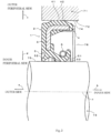
- Fig. 3 is a diagram illustrating a schematic configuration of a conventional sealing apparatus.
- a conventional sealing apparatus 100 at an atmospheric side inclined surface 102 on the opposite side of a sealed fluid side in the seal lip portion 101, a plurality of projections (screw projections 103) extending obliquely with respect to an axis and arranged at equal intervals.
- the screw projections 103 act as a screw pump to prevent the sealed fluid from leaking to an atmospheric side.
- US 2002/0012485 A1 discloses a sealed crankshaft bearing assembly for a two-stroke engine.
- the assembly includes a grease seal disposed between an inner races and an outer race.
- the grease seal includes a rigid support structure generally L-shaped in section, and a flexible sealing member.
- the flexible sealing member has a first and a second circumferential sealing lip as well as a chamber between the two lips that accommodates lubricant therein for lubricating the lips.
- grease or oil is used and the grease seal seals either type of lubricant.
- One specific grease that can be used for lubrication of the bearings is Kliiber Isoflex NB52, no. 004131, available from Klüber in Germany. This grease uses barium complex soap as a thickener and synthetic hydrocarbon oil as type of oil.
- Patent Literature 1 Japanese Patent Application Publication No. 2005-172061
- Patent Literature 2 US 2002/0012485 A1
- the sealed fluid does not flow when the engine starts.
- the sealed fluid does not circulate in the engine and is not supplied to the seal lip portion 101.
- the sealed fluid does not act as the lubricant for the seal lip portion 101, leading to lubrication failure of the seal lip portion 101 and progress in wear of the seal lip portion 101.
- the progress in wear of the seal lip portion 101 may result in wear of the screw projection 103 or a reduction of lip interference, which may deteriorate the pumping performance of the sealing apparatus 100 and may cause leakage of the sealed fluid.
- a sealing apparatus provides a sealing apparatus in accordance with claim 1.
- the sealing apparatus is sealing a gap between two members mutually relatively rotatable about an axis in an internal combustion engine, the sealing apparatus characterized by comprising: an elastic body portion which is an elastic body including an annular attaching portion attached to one of the two members and centered about the axis; and a seal portion in close contact with another of the two members in a manner in which the other of the two members is slidable, wherein the seal portion comprises: an annular seal lip portion centered about the axis; and an annular dust lip centered about the axis on an atmospheric side on an opposite side of a sealed fluid side with respect to the seal lip portion, wherein the seal lip portion comprises a lip tip portion which is an annular projecting body projecting toward the axis, and grease is applied to the seal lip portion, the grease contains at least one of a synthetic hydrocarbon oil and a mineral oil as a base oil and has a low temperature starting torque
- the grease is applied between the lip tip portion and the dust lip.
- the lip tip portion comprises: a sealed fluid side inclined surface which is an inclined surface on the sealed fluid side; an atmospheric side inclined surface which is an inclined surface on the atmospheric side; and a sliding surface contacting the other of the two members between the sealed fluid side inclined surface and the atmospheric side inclined surface in a manner in which the other of the two members is slidable, wherein the grease is applied to at least the sliding surface.
- the grease is applied to at least the sliding surface of the lip tip portion and the atmospheric side inclined surface.
- the grease is applied to a seal lip portion and thus can suppress wear of the seal lip portion due to sliding.
- the grease contains at least one of a synthetic hydrocarbon oil and a mineral oil as a base oil, has a low temperature starting torque of 25 N ⁇ cm or less at -30°C, and thus the fluidity of grease is high even in a low temperature environment. For this reason, in a low temperature environment, the grease is supplied to the sliding surface of the seal lip portion, thus suppressing wear of the seal lip portion in a low temperature environment. The suppression of wear of the seal lip portion can serve to prevent leakage of the sealed fluid.
- grease is applied between the lip tip portion and the dust lip, thus facilitating supply of the grease to the sliding surface of the seal lip portion and suppressing wear of the seal lip portion in a low temperature environment.
- grease is applied to at least the sliding surface of the lip tip portion, thus effectively suppressing wear of the seal lip portion in a low temperature environment.
- grease is applied to at least the sliding surface and an atmospheric side inclined surface.
- Grease is applied to the sliding surface and the grease applied to the atmospheric side inclined surface is supplied to the sliding surface of the seal lip portion, thus more continuously suppressing wear of the sliding surface in a low temperature environment.
- Fig. 1 is a sectional diagram taken along an axis of a sealing apparatus for illustrating a schematic configuration of the sealing apparatus according to an embodiment of the present invention.
- a sealing apparatus 1 includes an elastic body portion 2 made of an annular elastic body and centered about an axis x; and a reinforcing ring 3 made of an annular metal and centered about the axis x.
- the elastic body of the elastic body portion 2 include various rubber materials.
- the various rubber materials include synthetic rubbers such as nitrile rubber (NBR), hydrogenated nitrile rubber (H-NBR), acrylic rubber (ACM), or fluorine rubber (FKM).
- the metal of the reinforcing ring 3 include stainless steel or SPCC (cold rolled steel sheet).
- the sealing apparatus 1 is used to seal a gap between two members mutually relatively rotatable about the axis x.
- the elastic body portion 2 includes an attaching portion 4 fitted in an opening of a portion to be attached such as a casing or housing as one of the two mutually relatively rotatable members; and a seal portion 5 in close contact with an outer peripheral surface of the other of the two members such as a shaft to be inserted into the elastic body portion 2 in a manner in which the outer peripheral surface is slidable.
- the attaching portion 4 is a cylindrical annular portion located on an outer peripheral side of the elastic body portion 2 and centered about the axis x.
- An outer peripheral surface 41 as a peripheral surface on the outer peripheral side of the attaching portion 4 is defined based on an interference portion 42 having a thickness (radial dimension) corresponding to the dimension of the unillustrated opening of the portion to be attached.
- the term "outer side” refers to a direction of arrow a (see Fig. 1 ) in a direction of the axis x
- the term “inner side” refers to a direction of arrow b (see Fig. 1 ) in the direction of the axis x.
- the inner side refers to a direction (sealed fluid side) facing a region where the sealed fluid such as lubricating oil is present
- the outer side refers to a direction (atmospheric side) facing a region where the sealed fluid is not or should not be present
- the term "outer peripheral side” refers to a direction (direction of arrow c in Fig.1 ) away from the axis x in a direction perpendicular to the axis x
- the term “inner peripheral side” refers to a direction (direction of arrow d in Fig.1 ) approaching the axis x.
- the seal portion 5 is a cylindrical annular portion located on the inner peripheral side of the elastic body portion 2 and centered about the axis x.
- the seal portion 5 includes a seal lip portion 51 as illustrated in Fig. 1 .
- the seal portion 5 includes a dust lip portion 52 located on the outer side (atmospheric side) with respect to the seal lip portion 51.
- the dust lip portion 52 is provided to prevent foreign matter such as dust from entering a contact portion between the seal lip portion 51 and a shaft (unillustrated).
- the dust lip portion 52 is an annular member centered about the axis x and extending obliquely from an inner peripheral side end portion of the seal portion 5 toward the outer side in the inner peripheral direction.
- the seal lip portion 51 includes a lip tip portion 53 located on an inner side portion on the inner peripheral side of the seal lip portion 51.
- the lip tip portion 53 is an annular projection body whose shape of the cross section including the axis x (hereinafter may be simply referred to as a cross section) is a wedge shape projecting in the inner peripheral direction and centered about the axis x. More specifically, the lip tip portion 53 includes a sealed fluid side inclined surface 54, a sliding surface 55, and an atmospheric side inclined surface 56 in the order from the inner side (sealed fluid side).
- the above projection body is defined by the above surfaces 54 to 56.
- the sealed fluid side inclined surface 54 is an inclined surface on the sealed fluid side. Specifically, as illustrated in Fig. 1 , the sealed fluid side inclined surface 54 is an annular surface centered about the axis x and a conical surface (tapered surface) extending tapered in the direction of the axis x. The tapered surface of the sealed fluid side inclined surface 54 decreases in diameter as it progresses from the inner side toward the outer side in the direction of the axis x.
- the atmospheric side inclined surface 56 is an inclined surface on the atmospheric side. Specifically, as illustrated in Fig. 1 , the atmospheric side inclined surface 56 is an annular surface centered about the axis x and a conical surface (tapered surface) extending tapered in the direction of the axis x. The tapered surface of the atmospheric side inclined surface 56 increases in diameter as it progresses from the inner side toward the outer side in the direction of the axis x.
- the sliding surface 55 is a cylindrical surface extending between the sealed fluid side inclined surface 54 and the atmospheric side inclined surface 56 contacting the unillustrated shaft in a manner such that the shaft is slidable.
- the atmospheric side inclined surface 56 of the lip tip portion 53 includes a screw projection 57 which has a plurality of projections 58 whose tip ends reach the vicinity of the sliding surface 55.
- the plurality of projections 58 of the screw projection 57 are arranged in parallel with each other at predetermined intervals in the circumferential direction.
- the projections 58 are projections protruding in the inner peripheral direction and extending obliquely with respect to the axis x.
- the shape and size of the projection 58 are conventionally known and are not limited to the above-described shape and size.
- the lip portion 51 includes an annular recessed portion 59 located on an outer peripheral side surface facing the lip tip portion 53.
- an annular spring 6 of the sealing apparatus 1 is accommodated in the recessed portion 59. The spring 6 urges the lip tip portion 53 in the inner peripheral direction.
- the elastic body portion 2 includes a disk portion 21 having a hollow disk shape and centered about the axis x.
- the disk portion 21 connects the attaching portion 4 and the seal portion 5 at each end portion thereof on the outer side.
- the reinforcing ring 3 is an annular member having a substantially L-shaped cross section and centered about the axis x. As illustrated in Fig. 1 , the reinforcing ring 3 is partially covered with the elastic body portion 2 and is integrated with the elastic body portion 2. In the present embodiment, a part of the inner side surface of the reinforcing ring 3 is exposed without being covered with the elastic body portion 2, but a part of the reinforcing ring 3 may be covered with the elastic body portion 2 or the whole of the reinforcing ring 3 may be covered with the elastic body portion 2 as long as the reinforcing ring 3 has a structure capable of reinforcing the elastic body portion 2.
- the reinforcing ring 3 is manufactured by, for example, press working or forging, and most of the elastic body portion 2 is molded with a mold by cross-linking (vulcanization) to be described later. During the cross-linking molding, the reinforcing ring 3 is placed inside the mold, and then the elastic body portion 2 is adhered to the reinforcing ring 3 by cross-linking bonding, and then, the elastic body portion 2 is integrally molded with the reinforcing ring 3.
- cross-linking vulcanization
- grease G is applied to the seal lip portion 51.
- the grease G is applied between the lip tip portion 53 and the dust lip portion 52.
- the grease G may be applied entirely between the lip tip portion 53 and the dust lip portion 52 or may be applied partially between the lip tip portion 53 and the dust lip portion 52.
- the grease G may be applied only to the sliding surface 55 or may be applied only to the sliding surface 55 and the atmospheric side inclined surface 56.
- the grease for use in the present embodiment contains at least one of a synthetic hydrocarbon oil and a mineral oil as a base oil.
- the grease preferably contains a synthetic hydrocarbon oil as the base oil.
- synthetic hydrocarbon oils include poly- ⁇ -olefins, ethylene- ⁇ -olefin copolymers, polybutenes, alkylbenzenes, and alkylnaphthalenes.
- mineral oils include paraffinic mineral oils, olefinic mineral oils and naphthenic mineral oils. These synthetic hydrocarbon oils and mineral oils may be used singly or in mixture.
- the base oil content of the grease is preferably 60 to 90 wt%.
- the grease in addition contains a thickener selected from a group consisting of metal soaps and metal complex soaps.
- the metal soaps include lithium soaps, sodium soaps, potassium soaps, calcium soaps, barium soaps and aluminum soaps.
- the metal complex soaps include lithium complex soaps, calcium complex soaps, and barium complex soaps. These thickeners may be used singly or in mixture.
- the thickener content of the grease is preferably 5 to 50 wt%, and more preferably 10 to 40 wt%.
- the grease may further contain additives such as other thickeners, antioxidants, rust inhibitors, corrosion inhibitors, extreme pressure agents, oiliness agents, solid lubricants, conductivity improvers, and the like, as needed.
- additives such as other thickeners, antioxidants, rust inhibitors, corrosion inhibitors, extreme pressure agents, oiliness agents, solid lubricants, conductivity improvers, and the like, as needed.
- antioxidants examples include phenolic antioxidants such as 2,6-di-tert-butyl-4-methylphenol and 4,4'-methylenebis(2,6-di-tert-butylphenol); amine type antioxidants such as alkyldiphenylamines, triphenylamines, phenyl- ⁇ -naphthylamines, alkylated phenyl- ⁇ -naphthylamines, phenothiazines, alkylated phenothiazines and; furthermore, phosphoric acid type antioxidants, sulfur type antioxidants and the like.
- phenolic antioxidants such as 2,6-di-tert-butyl-4-methylphenol and 4,4'-methylenebis(2,6-di-tert-butylphenol)
- amine type antioxidants such as alkyldiphenylamines, triphenylamines, phenyl- ⁇ -naphthylamines, alkylated phenyl- ⁇ -
- rust inhibitors examples include fatty acids, fatty acid metal salts, fatty acid amines, alkylsulfonic acid metal salts, alkylsulfonic acid amine salts, oxidized paraffins, polyoxyethylene alkyl ethers, and the like.
- corrosion inhibitors examples include penzotriazoles, benzimidazoles, thiadiazoles, and the like.
- extreme pressure agents examples include phosphorus-based compounds such as phosphoric acid esters, phosphorous acid esters, and phosphoric ester amine salts; sulfur compounds such as sulfides and disulfides; sulfur-based metal salts such as dialkyldithiophosphoric acid metal salts and dialkyldithiocarbamic acid metal salts; chlorinated compounds such as chlorinated paraffins and chlorinated diphenyl; and the like.
- oiliness agents examples include fatty acids or esters thereof, higher alcohols, polyhydric alcohols or esters thereof, aliphatic esters, aliphatic amines, fatty acid monoglycerides, a montan wax, an amide-based wax, and the like.
- solid lubricants examples include molybdenum disulfide, carbon black, graphite, boron nitride, silane nitride, melamine cyanurate, and the like.
- the worked penetration of the grease is preferably 265 to 295. Note that the worked penetration is measured at 25°C based on JIS K 2220.
- the low temperature starting torque of the grease is 25 N ⁇ cm or less. Furthermore, the low temperature starting torque of the grease is preferably 12 N ⁇ cm or less. When the low temperature starting torque exceeds 25 N ⁇ cm, the fluidity decreases in a low temperature environment. This leads to insufficient action as the lubricant in an assembled state of the sealing apparatus 1 in a low temperature environment, which is not preferable because this promotes wear of the seal lip portion 51 of the sealing apparatus 1. Note that the low temperature starting torque is measured at -30°C based on JIS K2220.
- the sealing apparatus 1 according to the present embodiment is assumed to be disposed between two mutually relatively rotatable members, namely, a crankcase and a crankshaft of an automobile engine. Specifically, the sealing apparatus 1 is assumed to be disposed in a gap and to seal the gap between a shaft hole of the crankcase and the crankshaft inserted into the shaft hole. Note that the sealing apparatus 1 according to the present invention is not limited to the one disposed between a crankshaft and a crankcase of an automobile engine. The sealing apparatus 1 according to the present invention can be applied to seal a gap between two mutually relatively rotatable members in a vehicle or a general-purpose machine.
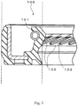
- Fig. 2 is a partial sectional diagram for illustrating the usage state of the sealing apparatus 1 according to the embodiment of the present invention.
- a crankcase 71 includes a shaft hole 72 as a cylindrical opening.
- a crankshaft 73 is inserted into the shaft hole 72.
- the sealing apparatus 1 is attached to a gap 76 and to seal the gap 76 between an inner peripheral surface 74 which is a surface on an inner periphery of the shaft hole 72 and an outer peripheral surface 75 which is a surface of the crankshaft 73. Note that the grease G has been applied to the seal lip portion 51 in advance.
- the sealing apparatus 1 is attached to the crankcase 71 such that the attaching portion 4 is fitted into the shaft hole 72 of the crankcase 71. More specifically, the interference portion 42 of the attaching portion 4 is compressed between the reinforcing ring 3 and the inner peripheral surface 74 of the shaft hole 72, and then the sealing apparatus 1 is fitted and strongly fixed to the crankcase 71.
- the outer peripheral surface 41 of the elastic body portion 2 closely contacts the inner peripheral surface 74 of the shaft hole 72 in a liquid-tight manner.
- the crankshaft 73 is inserted into the seal portion 5, and the lip tip portion 53 (sliding surface 55) of the seal lip portion 51 contacts the outer peripheral surface 75 of the shaft 73.
- the gap 76 is sealed by the fitting of the attaching portion 4 and the contacting of the lip tip portion 53.
- the sealing apparatus 1 of the embodiment of the present invention grease is applied to the seal lip portion 51 and thus the wear of the seal lip portion 51 due to sliding can be suppressed.
- the grease contains at least one of a synthetic hydrocarbon oil and a mineral oil as a base oil and the grease has a low temperature starting torque of 25 N/cm or less, and thus the fluidity of grease is high even in a low temperature environment and the effect of suppressing the wear of the seal lip portion 51 is considerable.
- the suppression of the wear of the seal lip portion 51 can prevent leakage of the sealed fluid.
- the present invention is not limited to the above embodiments of the present invention and may include all aspects included in the concept of the present invention and the scope of the claims.
- the above components may be combined appropriately and selectively to solve at least a part of the above problems and to exert at least a part of the above effects.
- the shape, material, arrangement, size, and the like of each component in the above embodiments can be appropriately changed according to a specific application of the present invention.
- the shapes of the attaching portion 4, the seal portion 5, and the reinforcing ring 3 are not limited to the above shapes.
- a rear differential side oil seal which is an acrylic rubber oil seal having an inner diameter of 37 mm was used as sealing apparatus according to present examples and comparative examples.
- greases used in the sealing apparatus according to the present examples 1 to 3 and the comparative examples 1 to 3 were listed in Table 1 to be described later.
- Lithium soap Li salt of fatty acid monocarboxylic acid having 12 to 24 carbon atoms (it is noted that one contains at least one hydrogen group or one contains no hydrogen group)
- Barium complex soap complex soap of fatty acid dicarboxylic acid and monoaminocarboxylic acid.
- the low temperature starting torque was measured according to JIS K2220 at -30°C.
- Grease was applied to a sliding surface of an acrylic rubber oil seal having an inner diameter of 37 mm and was subjected to a rotation test at -30°C.
- the rotation test was performed in a state in which a lubricating oil (mineral oil gear oil having a viscosity grade of 75 W-90 and a pour point of -23°C) was filled up to the center of the rotating shaft. 100 cycles were repeated, assuming that one cycle refers to a pattern of rotating at a low temperature of -30°C for 10 minutes in the normal rotation direction, then stopping and cooling. Then, the wear width of the sliding surface was observed with a microscope. A wear width of 0.5 mm or less was accepted, and a wear width of more than 0.5 mm was rejected.
- the grease applied to the seal lip portion contains a synthetic hydrocarbon oil as the base oil and has a low temperature starting torque of 25 N ⁇ cm or less, whereby a considerable effect of suppressing the wear of the seal lip portion is exerted even in a low temperature environment of -30°C.
Description
- The present invention relates to a sealing apparatus, and particularly relates to a sealing apparatus suitably usable for an internal combustion engine of a vehicle or a general-purpose machine in a low temperature environment.
- Conventionally, a sealing apparatus has been used in an engine of a vehicle such as an automobile to seal a gap between two mutually relatively rotating members. For example, the sealing apparatus is used to seal a gap between a rotating shaft such as a crankshaft and a casing through which this shaft is inserted.
- When the sealing apparatus is installed in the gap between the shaft and the casing of the engine, a seal lip portion of the sealing apparatus contacts the shaft, and then, a sealed space is formed in the casing. At the contact portion between the seal lip portion of the sealing apparatus and the shaft, engine oil as a fluid to be sealed (hereinafter referred to as a sealed fluid) acts as a lubricant. The sealed fluid acts as a lubricant to thereby suppress wear of the seal lip portion of the sealing apparatus.
-
Fig. 3 is a diagram illustrating a schematic configuration of a conventional sealing apparatus. As illustrated inFig. 3 , in aconventional sealing apparatus 100, at an atmospheric sideinclined surface 102 on the opposite side of a sealed fluid side in theseal lip portion 101, a plurality of projections (screw projections 103) extending obliquely with respect to an axis and arranged at equal intervals. When the shaft is rotated, the screw projections 103 act as a screw pump to prevent the sealed fluid from leaking to an atmospheric side. (For example, see Patent Literature 1). -
US 2002/0012485 A1 discloses a sealed crankshaft bearing assembly for a two-stroke engine. The assembly includes a grease seal disposed between an inner races and an outer race. The grease seal includes a rigid support structure generally L-shaped in section, and a flexible sealing member. The flexible sealing member has a first and a second circumferential sealing lip as well as a chamber between the two lips that accommodates lubricant therein for lubricating the lips. In contrast, for the lubrication of the bearings, grease or oil is used and the grease seal seals either type of lubricant. One specific grease that can be used for lubrication of the bearings is Kliiber Isoflex NB52, no. 004131, available from Klüber in Germany. This grease uses barium complex soap as a thickener and synthetic hydrocarbon oil as type of oil. - Patent Literature 1:
Japanese Patent Application Publication No. 2005-172061 - Patent Literature 2:
US 2002/0012485 A1 - However, in a low temperature environment where the sealed fluid is at a pour point or below, the sealed fluid does not flow when the engine starts. Thus, the sealed fluid does not circulate in the engine and is not supplied to the
seal lip portion 101. Accordingly, the sealed fluid does not act as the lubricant for theseal lip portion 101, leading to lubrication failure of theseal lip portion 101 and progress in wear of theseal lip portion 101. The progress in wear of theseal lip portion 101 may result in wear of the screw projection 103 or a reduction of lip interference, which may deteriorate the pumping performance of thesealing apparatus 100 and may cause leakage of the sealed fluid. - In order to solve such problems, there can be considered a method of changing a sealed fluid for use in a low temperature environment to another sealed fluid having a lower pour point. However, the change of the sealed fluid may adversely affect other mechanisms of the engine, and thus the sealed fluid cannot be easily changed. Alternatively, there can be considered a method of changing the material of the sealing apparatus. However, the change of the material affects various properties such as heat resistance and pumping performance of the sealing apparatus, so it is difficult to change the material while maintaining the required properties of the sealing apparatus. Consequently, there has been a demand for a sealing apparatus capable of improving wear resistance in a low temperature environment while maintaining the required properties of the sealing apparatus without adversely affecting the mechanisms of the engine.
- To solve the above problems, it is an object of the present invention to provide a sealing apparatus capable of suppressing wear of a seal lip portion in a low temperature environment.
- In order to achieve the above object, a sealing apparatus according to the present invention provides a sealing apparatus in accordance with
claim 1. The sealing apparatus is sealing a gap between two members mutually relatively rotatable about an axis in an internal combustion engine, the sealing apparatus characterized by comprising: an elastic body portion which is an elastic body including an annular attaching portion attached to one of the two members and centered about the axis; and a seal portion in close contact with another of the two members in a manner in which the other of the two members is slidable, wherein the seal portion comprises: an annular seal lip portion centered about the axis; and an annular dust lip centered about the axis on an atmospheric side on an opposite side of a sealed fluid side with respect to the seal lip portion, wherein the seal lip portion comprises a lip tip portion which is an annular projecting body projecting toward the axis, and grease is applied to the seal lip portion, the grease contains at least one of a synthetic hydrocarbon oil and a mineral oil as a base oil and has a low temperature starting torque of 25 N/cm or less at -30°C. In accordance with the invention, the grease also contains a thickener selected from a group consisting of metal soaps and metal complex soaps. - In the sealing apparatus according to an aspect of the present invention, the grease is applied between the lip tip portion and the dust lip.
- In the sealing apparatus according to an aspect of the present invention, the lip tip portion comprises: a sealed fluid side inclined surface which is an inclined surface on the sealed fluid side; an atmospheric side inclined surface which is an inclined surface on the atmospheric side; and a sliding surface contacting the other of the two members between the sealed fluid side inclined surface and the atmospheric side inclined surface in a manner in which the other of the two members is slidable, wherein the grease is applied to at least the sliding surface.
- In the sealing apparatus according to an aspect of the present invention, the grease is applied to at least the sliding surface of the lip tip portion and the atmospheric side inclined surface.
- According to a sealing apparatus of the present invention, grease is applied to a seal lip portion and thus can suppress wear of the seal lip portion due to sliding. In particular, the grease contains at least one of a synthetic hydrocarbon oil and a mineral oil as a base oil, has a low temperature starting torque of 25 N▪cm or less at -30°C, and thus the fluidity of grease is high even in a low temperature environment. For this reason, in a low temperature environment, the grease is supplied to the sliding surface of the seal lip portion, thus suppressing wear of the seal lip portion in a low temperature environment. The suppression of wear of the seal lip portion can serve to prevent leakage of the sealed fluid.
- According to a sealing apparatus of the present invention, grease is applied between the lip tip portion and the dust lip, thus facilitating supply of the grease to the sliding surface of the seal lip portion and suppressing wear of the seal lip portion in a low temperature environment.
- According to a sealing apparatus of the present invention, grease is applied to at least the sliding surface of the lip tip portion, thus effectively suppressing wear of the seal lip portion in a low temperature environment.
- According to a sealing apparatus of the present invention, grease is applied to at least the sliding surface and an atmospheric side inclined surface. Grease is applied to the sliding surface and the grease applied to the atmospheric side inclined surface is supplied to the sliding surface of the seal lip portion, thus more continuously suppressing wear of the sliding surface in a low temperature environment.
-
- [
Fig. 1 ] A sectional diagram taken along an axis of a sealing apparatus for illustrating a schematic configuration of the sealing apparatus according to an embodiment of the present invention. - [
Fig. 2 ] A partial sectional diagram for illustrating a usage state of the sealing apparatus according to the embodiment of the present invention. - [
Fig. 3 ] A sectional diagram for illustrating the configuration of a conventional sealing apparatus. - Hereinafter, embodiments of the present invention will be described with reference to the accompanying drawings.
-
Fig. 1 is a sectional diagram taken along an axis of a sealing apparatus for illustrating a schematic configuration of the sealing apparatus according to an embodiment of the present invention. - As illustrated in
Fig. 1 , asealing apparatus 1 according to the embodiment of the present invention includes anelastic body portion 2 made of an annular elastic body and centered about an axis x; and a reinforcingring 3 made of an annular metal and centered about the axis x. Examples of the elastic body of theelastic body portion 2 include various rubber materials. Examples of the various rubber materials include synthetic rubbers such as nitrile rubber (NBR), hydrogenated nitrile rubber (H-NBR), acrylic rubber (ACM), or fluorine rubber (FKM). Examples of the metal of the reinforcingring 3 include stainless steel or SPCC (cold rolled steel sheet). Thesealing apparatus 1 is used to seal a gap between two members mutually relatively rotatable about the axis x. - The
elastic body portion 2 includes an attachingportion 4 fitted in an opening of a portion to be attached such as a casing or housing as one of the two mutually relatively rotatable members; and aseal portion 5 in close contact with an outer peripheral surface of the other of the two members such as a shaft to be inserted into theelastic body portion 2 in a manner in which the outer peripheral surface is slidable. - The attaching
portion 4 is a cylindrical annular portion located on an outer peripheral side of theelastic body portion 2 and centered about the axis x. An outerperipheral surface 41 as a peripheral surface on the outer peripheral side of the attachingportion 4 is defined based on aninterference portion 42 having a thickness (radial dimension) corresponding to the dimension of the unillustrated opening of the portion to be attached. For convenience of description, as used herein, the term "outer side" refers to a direction of arrow a (seeFig. 1 ) in a direction of the axis x, and the term "inner side" refers to a direction of arrow b (seeFig. 1 ) in the direction of the axis x. More specifically, in the usage state, the inner side refers to a direction (sealed fluid side) facing a region where the sealed fluid such as lubricating oil is present, and the outer side refers to a direction (atmospheric side) facing a region where the sealed fluid is not or should not be present. In addition, the term "outer peripheral side" refers to a direction (direction of arrow c inFig.1 ) away from the axis x in a direction perpendicular to the axis x, and the term "inner peripheral side" refers to a direction (direction of arrow d inFig.1 ) approaching the axis x. - The
seal portion 5 is a cylindrical annular portion located on the inner peripheral side of theelastic body portion 2 and centered about the axis x. Theseal portion 5 includes aseal lip portion 51 as illustrated inFig. 1 . Further, theseal portion 5 includes adust lip portion 52 located on the outer side (atmospheric side) with respect to theseal lip portion 51. Thedust lip portion 52 is provided to prevent foreign matter such as dust from entering a contact portion between theseal lip portion 51 and a shaft (unillustrated). As illustrated inFig. 1 , thedust lip portion 52 is an annular member centered about the axis x and extending obliquely from an inner peripheral side end portion of theseal portion 5 toward the outer side in the inner peripheral direction. - As illustrated in
Fig. 1 , theseal lip portion 51 includes alip tip portion 53 located on an inner side portion on the inner peripheral side of theseal lip portion 51. As illustrated inFig. 1 , thelip tip portion 53 is an annular projection body whose shape of the cross section including the axis x (hereinafter may be simply referred to as a cross section) is a wedge shape projecting in the inner peripheral direction and centered about the axis x. More specifically, thelip tip portion 53 includes a sealed fluid side inclinedsurface 54, a slidingsurface 55, and an atmospheric side inclinedsurface 56 in the order from the inner side (sealed fluid side). The above projection body is defined by theabove surfaces 54 to 56. - The sealed fluid side inclined
surface 54 is an inclined surface on the sealed fluid side. Specifically, as illustrated inFig. 1 , the sealed fluid side inclinedsurface 54 is an annular surface centered about the axis x and a conical surface (tapered surface) extending tapered in the direction of the axis x. The tapered surface of the sealed fluid side inclinedsurface 54 decreases in diameter as it progresses from the inner side toward the outer side in the direction of the axis x. - The atmospheric side inclined
surface 56 is an inclined surface on the atmospheric side. Specifically, as illustrated inFig. 1 , the atmospheric side inclinedsurface 56 is an annular surface centered about the axis x and a conical surface (tapered surface) extending tapered in the direction of the axis x. The tapered surface of the atmospheric side inclinedsurface 56 increases in diameter as it progresses from the inner side toward the outer side in the direction of the axis x. - The sliding
surface 55 is a cylindrical surface extending between the sealed fluid side inclinedsurface 54 and the atmospheric side inclinedsurface 56 contacting the unillustrated shaft in a manner such that the shaft is slidable. - The atmospheric side inclined
surface 56 of thelip tip portion 53 includes ascrew projection 57 which has a plurality ofprojections 58 whose tip ends reach the vicinity of the slidingsurface 55. The plurality ofprojections 58 of thescrew projection 57 are arranged in parallel with each other at predetermined intervals in the circumferential direction. Theprojections 58 are projections protruding in the inner peripheral direction and extending obliquely with respect to the axis x. The shape and size of theprojection 58 are conventionally known and are not limited to the above-described shape and size. - Further, the
lip portion 51 includes an annular recessedportion 59 located on an outer peripheral side surface facing thelip tip portion 53. In the recessedportion 59, anannular spring 6 of thesealing apparatus 1 is accommodated. Thespring 6 urges thelip tip portion 53 in the inner peripheral direction. - In addition, as illustrated in
Fig. 1 , theelastic body portion 2 includes adisk portion 21 having a hollow disk shape and centered about the axis x. Thedisk portion 21 connects the attachingportion 4 and theseal portion 5 at each end portion thereof on the outer side. - The reinforcing
ring 3 is an annular member having a substantially L-shaped cross section and centered about the axis x. As illustrated inFig. 1 , the reinforcingring 3 is partially covered with theelastic body portion 2 and is integrated with theelastic body portion 2. In the present embodiment, a part of the inner side surface of the reinforcingring 3 is exposed without being covered with theelastic body portion 2, but a part of the reinforcingring 3 may be covered with theelastic body portion 2 or the whole of the reinforcingring 3 may be covered with theelastic body portion 2 as long as the reinforcingring 3 has a structure capable of reinforcing theelastic body portion 2. - The reinforcing
ring 3 is manufactured by, for example, press working or forging, and most of theelastic body portion 2 is molded with a mold by cross-linking (vulcanization) to be described later. During the cross-linking molding, the reinforcingring 3 is placed inside the mold, and then theelastic body portion 2 is adhered to the reinforcingring 3 by cross-linking bonding, and then, theelastic body portion 2 is integrally molded with the reinforcingring 3. - According to the
sealing apparatus 1 of the present embodiment, grease G is applied to theseal lip portion 51. Specifically, the grease G is applied between thelip tip portion 53 and thedust lip portion 52. The grease G may be applied entirely between thelip tip portion 53 and thedust lip portion 52 or may be applied partially between thelip tip portion 53 and thedust lip portion 52. For example, the grease G may be applied only to the slidingsurface 55 or may be applied only to the slidingsurface 55 and the atmospheric side inclinedsurface 56. - The grease for use in the present embodiment contains at least one of a synthetic hydrocarbon oil and a mineral oil as a base oil. The grease preferably contains a synthetic hydrocarbon oil as the base oil. Examples of synthetic hydrocarbon oils include poly-α-olefins, ethylene-α-olefin copolymers, polybutenes, alkylbenzenes, and alkylnaphthalenes. Examples of mineral oils include paraffinic mineral oils, olefinic mineral oils and naphthenic mineral oils. These synthetic hydrocarbon oils and mineral oils may be used singly or in mixture. The base oil content of the grease is preferably 60 to 90 wt%.
- In accordance with the invention, the grease in addition contains a thickener selected from a group consisting of metal soaps and metal complex soaps. Examples of the metal soaps include lithium soaps, sodium soaps, potassium soaps, calcium soaps, barium soaps and aluminum soaps. Examples of the metal complex soaps include lithium complex soaps, calcium complex soaps, and barium complex soaps. These thickeners may be used singly or in mixture. The thickener content of the grease is preferably 5 to 50 wt%, and more preferably 10 to 40 wt%.
- In addition, the grease may further contain additives such as other thickeners, antioxidants, rust inhibitors, corrosion inhibitors, extreme pressure agents, oiliness agents, solid lubricants, conductivity improvers, and the like, as needed.
- Examples of the antioxidants include phenolic antioxidants such as 2,6-di-tert-butyl-4-methylphenol and 4,4'-methylenebis(2,6-di-tert-butylphenol); amine type antioxidants such as alkyldiphenylamines, triphenylamines, phenyl-α-naphthylamines, alkylated phenyl-α-naphthylamines, phenothiazines, alkylated phenothiazines and; furthermore, phosphoric acid type antioxidants, sulfur type antioxidants and the like.
- Examples of the rust inhibitors include fatty acids, fatty acid metal salts, fatty acid amines, alkylsulfonic acid metal salts, alkylsulfonic acid amine salts, oxidized paraffins, polyoxyethylene alkyl ethers, and the like.
- Examples of the corrosion inhibitors include penzotriazoles, benzimidazoles, thiadiazoles, and the like.
- Examples of the extreme pressure agents include phosphorus-based compounds such as phosphoric acid esters, phosphorous acid esters, and phosphoric ester amine salts; sulfur compounds such as sulfides and disulfides; sulfur-based metal salts such as dialkyldithiophosphoric acid metal salts and dialkyldithiocarbamic acid metal salts; chlorinated compounds such as chlorinated paraffins and chlorinated diphenyl; and the like.
- Examples of the oiliness agents include fatty acids or esters thereof, higher alcohols, polyhydric alcohols or esters thereof, aliphatic esters, aliphatic amines, fatty acid monoglycerides, a montan wax, an amide-based wax, and the like.
- Examples of the solid lubricants include molybdenum disulfide, carbon black, graphite, boron nitride, silane nitride, melamine cyanurate, and the like.
- In addition, the worked penetration of the grease is preferably 265 to 295. Note that the worked penetration is measured at 25°C based on JIS K 2220.
- Further, the low temperature starting torque of the grease is 25 N▪cm or less. Furthermore, the low temperature starting torque of the grease is preferably 12 N▪cm or less. When the low temperature starting torque exceeds 25 N▪cm, the fluidity decreases in a low temperature environment. This leads to insufficient action as the lubricant in an assembled state of the
sealing apparatus 1 in a low temperature environment, which is not preferable because this promotes wear of theseal lip portion 51 of thesealing apparatus 1. Note that the low temperature starting torque is measured at -30°C based on JIS K2220. - In the following, the usage state of the
sealing apparatus 1 having the configuration described above will be described. The sealingapparatus 1 according to the present embodiment is assumed to be disposed between two mutually relatively rotatable members, namely, a crankcase and a crankshaft of an automobile engine. Specifically, the sealingapparatus 1 is assumed to be disposed in a gap and to seal the gap between a shaft hole of the crankcase and the crankshaft inserted into the shaft hole. Note that the sealingapparatus 1 according to the present invention is not limited to the one disposed between a crankshaft and a crankcase of an automobile engine. The sealingapparatus 1 according to the present invention can be applied to seal a gap between two mutually relatively rotatable members in a vehicle or a general-purpose machine. -
Fig. 2 is a partial sectional diagram for illustrating the usage state of thesealing apparatus 1 according to the embodiment of the present invention. - As illustrated in
Fig. 2 , acrankcase 71 includes ashaft hole 72 as a cylindrical opening. Acrankshaft 73 is inserted into theshaft hole 72. The sealingapparatus 1 is attached to agap 76 and to seal thegap 76 between an innerperipheral surface 74 which is a surface on an inner periphery of theshaft hole 72 and an outerperipheral surface 75 which is a surface of thecrankshaft 73. Note that the grease G has been applied to theseal lip portion 51 in advance. - Specifically, the sealing
apparatus 1 is attached to thecrankcase 71 such that the attachingportion 4 is fitted into theshaft hole 72 of thecrankcase 71. More specifically, theinterference portion 42 of the attachingportion 4 is compressed between the reinforcingring 3 and the innerperipheral surface 74 of theshaft hole 72, and then thesealing apparatus 1 is fitted and strongly fixed to thecrankcase 71. The outerperipheral surface 41 of theelastic body portion 2 closely contacts the innerperipheral surface 74 of theshaft hole 72 in a liquid-tight manner. Thecrankshaft 73 is inserted into theseal portion 5, and the lip tip portion 53 (sliding surface 55) of theseal lip portion 51 contacts the outerperipheral surface 75 of theshaft 73. Thegap 76 is sealed by the fitting of the attachingportion 4 and the contacting of thelip tip portion 53. - As described above, according to the
sealing apparatus 1 of the embodiment of the present invention, grease is applied to theseal lip portion 51 and thus the wear of theseal lip portion 51 due to sliding can be suppressed. In particular, the grease contains at least one of a synthetic hydrocarbon oil and a mineral oil as a base oil and the grease has a low temperature starting torque of 25 N/cm or less, and thus the fluidity of grease is high even in a low temperature environment and the effect of suppressing the wear of theseal lip portion 51 is considerable. The suppression of the wear of theseal lip portion 51 can prevent leakage of the sealed fluid. - Hereinbefore, the embodiments of the present invention have been described, but the present invention is not limited to the above embodiments of the present invention and may include all aspects included in the concept of the present invention and the scope of the claims. Further, the above components may be combined appropriately and selectively to solve at least a part of the above problems and to exert at least a part of the above effects. For example, the shape, material, arrangement, size, and the like of each component in the above embodiments can be appropriately changed according to a specific application of the present invention. Specifically, the shapes of the attaching
portion 4, theseal portion 5, and the reinforcingring 3 are not limited to the above shapes. - Hereinafter, examples of the present invention will be described.
- A rear differential side oil seal which is an acrylic rubber oil seal having an inner diameter of 37 mm was used as sealing apparatus according to present examples and comparative examples. In addition, greases used in the sealing apparatus according to the present examples 1 to 3 and the comparative examples 1 to 3 were listed in Table 1 to be described later.
- To be the mixing ratio in Table 1, a base oil and a thickener were mixed and kneaded using a three-roll mill to obtain a uniform grease (examples 1 to 3, comparative examples 1 to 3). Table 1 lists the evaluation results of grease. The content of each component in Table 1 is represented by "wt%".
-
- Synthetic hydrocarbon oil A: poly-α-olefin (kinematic viscosity of 18 mm2/s at 40°C)
- Synthetic hydrocarbon oil B: poly-α-olefin (kinematic viscosity of 30 mm2/s at 40°C)
- Mineral oil A: paraffinic mineral oil (kinematic viscosity of 140 mm2/s at 40°C)
- Mineral oil B: paraffinic mineral oil (kinematic viscosity of 84 mm2/s at 40°C)
- Fluorine oil: perfluoropolyether (kinematic viscosity of 160 mm2/s at 40°C)
- Lithium soap: Li salt of fatty acid monocarboxylic acid having 12 to 24 carbon atoms (it is noted that one contains at least one hydrogen group or one contains no hydrogen group)
Barium complex soap: complex soap of fatty acid dicarboxylic acid and monoaminocarboxylic acid. - The low temperature starting torque was measured according to JIS K2220 at -30°C.
- Grease was applied to a sliding surface of an acrylic rubber oil seal having an inner diameter of 37 mm and was subjected to a rotation test at -30°C. The rotation test was performed in a state in which a lubricating oil (mineral oil gear oil having a viscosity grade of 75 W-90 and a pour point of -23°C) was filled up to the center of the rotating shaft. 100 cycles were repeated, assuming that one cycle refers to a pattern of rotating at a low temperature of -30°C for 10 minutes in the normal rotation direction, then stopping and cooling. Then, the wear width of the sliding surface was observed with a microscope. A wear width of 0.5 mm or less was accepted, and a wear width of more than 0.5 mm was rejected.
[Table 1] Example 1 Example 2 Example 3 Comparative Example 1 Comparative Example 2 Comparative Example 3 Base oil Synthetic hydrocarbon oil A 84 65 Synthetic hydrocarbon oil B 67 84 Mineral oil A 22 Mineral oil B 92 Fluorine oil 75 Thickener Li thium soap 16 13 8 16 Barium complex soap 33 PTFE 25 Low temperature starting torque (N · cm) 8 12 9.8 86 29 8. 8 Wear width (mm) 0. 5 0. 5 0. 4 1. 0 1. 2 0.8 - It was found from Table 1 that the wear was suppressed under a condition at -30°C in the examples 1 to 3 of applying grease containing at least one of a synthetic hydrocarbon oil and a mineral oil as the base oil and having a low temperature starting torque of 25 N/cm or less. Meanwhile, it was found that the wear width of the sliding surface was larger in the comparative examples 1 and 2 where the low temperature starting torque was more than 25 N▪cm. In addition, it was found that the wear width of the sliding surface was large in the comparative example 3 where the low temperature starting torque was 25 N▪cm or less but the grease containing fluorine oil as the base oil (not containing a synthetic hydrocarbon oil or a mineral oil) was used.
- As described above, in the examples 1 to 3 according to the present invention, the grease applied to the seal lip portion contains a synthetic hydrocarbon oil as the base oil and has a low temperature starting torque of 25 N▪cm or less, whereby a considerable effect of suppressing the wear of the seal lip portion is exerted even in a low temperature environment of -30°C.
-
- 1, 100 sealing apparatus
- 2 elastic body portion
- 3 reinforcing ring
- 4 attaching portion
- 5 seal portion
- 6 spring
- 21 disk portion
- 41 outer peripheral surface
- 42 interference portion
- 51, 101 seal lip portion
- 52 dust lip portion
- 53 lip tip portion
- 54 sealed fluid side inclined surface
- 55 sliding surface
- 56, 102 atmospheric side inclined surface
- 57, 103 screw projection
- 58 projection
- 59 recessed portion
- 71 crankcase
- 72 shaft hole
- 73 crankshaft
- 74 inner peripheral surface
- 75 outer peripheral surface
- 76 gap
- x axis
- G grease
Claims (6)
- A sealing apparatus (1) for sealing a gap (76) between two members (71, 73) mutually relatively rotatable about an axis (x) in an internal combustion engine, the sealing apparatus (1) comprising:an elastic body portion (2) which is an elastic body including an annular attaching portion (4) to be attached to one (71) of the two members (71, 73) and centered about the axis (x); and a seal portion (5) to be in close contact with another (73) of the two members (71, 73) in a manner in which the other (71) of the two members (71, 73) is slidable, whereinthe seal portion (5) comprises: an annular seal lip portion (51) centered about the axis (x); and an annular dust lip (52) centered about the axis (x) on an atmospheric side on an opposite side of a sealed fluid side with respect to the seal lip portion (51), whereinthe seal lip portion (51) comprises a lip tip portion (53) which is an annular projecting body projecting toward the axis (x), andgrease is applied to the seal lip portion (51), the grease, so as to suppress wear of the seal lip portion (51) in a low temperature environment, contains at least one of a synthetic hydrocarbon oil and a mineral oil as a base oil as well as at least one selected from a group consisting of metal soaps and metal complex soap as a thickener, and has a low temperature starting torque of 25 N▪cm or less at -30°C.
- The sealing apparatus (1) according to claim 1, characterized in that the grease is applied between the lip tip portion (53) and the dust lip (52).
- The sealing apparatus (1) according to claim 2, characterized in that the lip tip portion (53) comprises: a sealed fluid side inclined surface (54) which is an inclined surface intended to be placed on the sealed fluid side; an atmospheric side inclined surface (56) which is an inclined surface intended to be placed on the atmospheric side; and a sliding surface (55) for contacting the other (73) of the two members (71, 73) between the sealed fluid side inclined surface (54) and the atmospheric side inclined surface (56) in a manner in which the other (73) of the two members (71, 73) is slidable, wherein the grease is applied to at least the sliding surface (55).
- The sealing apparatus (1) according to claim 3, characterized in that the grease is applied to at least the sliding surface (55) of the lip tip portion (53) and the atmospheric side inclined surface (56).
- The sealing apparatus (1) according to one of claims 1 to 4, characterized in that the mineral oil is a paraffinic mineral oil.
- The sealing apparatus (1) according to one of claims 1 to 5, characterized in that the synthetic hydrocarbon oil is poly-α-olefin.
Applications Claiming Priority (2)
| Application Number | Priority Date | Filing Date | Title |
|---|---|---|---|
| JP2015096239 | 2015-05-11 | ||
| PCT/JP2016/063654 WO2016181900A1 (en) | 2015-05-11 | 2016-05-06 | Sealing device |
Publications (3)
| Publication Number | Publication Date |
|---|---|
| EP3293424A1 EP3293424A1 (en) | 2018-03-14 |
| EP3293424A4 EP3293424A4 (en) | 2019-02-13 |
| EP3293424B1 true EP3293424B1 (en) | 2023-02-01 |
Family
ID=57248063
Family Applications (1)
| Application Number | Title | Priority Date | Filing Date |
|---|---|---|---|
| EP16792625.2A Active EP3293424B1 (en) | 2015-05-11 | 2016-05-06 | Sealing apparatus |
Country Status (7)
| Country | Link |
|---|---|
| US (1) | US10605368B2 (en) |
| EP (1) | EP3293424B1 (en) |
| JP (1) | JP6830060B2 (en) |
| CN (1) | CN107532721A (en) |
| CA (1) | CA2985453C (en) |
| RU (1) | RU2673949C1 (en) |
| WO (1) | WO2016181900A1 (en) |
Families Citing this family (5)
| Publication number | Priority date | Publication date | Assignee | Title |
|---|---|---|---|---|
| CN111465788B (en) | 2017-12-27 | 2022-09-20 | Nok株式会社 | Sealing device |
| JP6967155B2 (en) * | 2018-07-24 | 2021-11-17 | Nok株式会社 | Sealing device |
| JP7368936B2 (en) * | 2018-09-27 | 2023-10-25 | 株式会社バルカー | Fitting with seal member |
| US20220018441A1 (en) * | 2019-03-20 | 2022-01-20 | Nok Corporation | Sealing apparatus |
| US20220145936A1 (en) * | 2019-05-08 | 2022-05-12 | Nok Corporation | Sealing device |
Citations (2)
| Publication number | Priority date | Publication date | Assignee | Title |
|---|---|---|---|---|
| CN203823070U (en) * | 2013-11-21 | 2014-09-10 | 无锡恩福油封有限公司 | Oil seal |
| JP2015075180A (en) * | 2013-10-09 | 2015-04-20 | 日本精工株式会社 | Hub unit bearing |
Family Cites Families (13)
| Publication number | Priority date | Publication date | Assignee | Title |
|---|---|---|---|---|
| JPS60184461U (en) * | 1984-05-17 | 1985-12-06 | エヌオーケー株式会社 | oil seal |
| RU2052698C1 (en) * | 1992-04-20 | 1996-01-20 | Юрий Леонидович Кузнецов | Sealing collar |
| US6712519B2 (en) * | 2000-07-28 | 2004-03-30 | Bombardier-Rotax Gmbh | Sealed bearing |
| GB0202841D0 (en) * | 2002-02-07 | 2002-03-27 | Johnson Electric Sa | Blower motor |
| JP2005172061A (en) * | 2003-12-09 | 2005-06-30 | Nok Corp | Sealing device |
| RU74579U1 (en) * | 2008-02-12 | 2008-07-10 | Александр Вячеславович Выборнов | ROD TYPE DRIPPER |
| JP5593677B2 (en) * | 2009-10-29 | 2014-09-24 | 日本精工株式会社 | Grease composition for railway axle bearings and rolling bearings for railway axle support |
| US8969269B2 (en) * | 2011-06-24 | 2015-03-03 | Chevron U.S.A. Inc. | Lubricating grease composition |
| JP5800148B2 (en) * | 2011-12-21 | 2015-10-28 | Nok株式会社 | Engine rear seal |
| JP2013133902A (en) * | 2011-12-27 | 2013-07-08 | Nsk Ltd | Seal device for hub bearing |
| JP2015048904A (en) * | 2013-09-02 | 2015-03-16 | Nok株式会社 | Sealing device |
| JP3189592U (en) * | 2014-01-07 | 2014-03-20 | Nok株式会社 | Oil seal |
| CN104327926A (en) * | 2014-10-25 | 2015-02-04 | 中国石油化工股份有限公司 | Lubricating grease composition for automobile door opening stoppers and preparation method thereof |
-
2016
- 2016-05-06 CN CN201680026154.5A patent/CN107532721A/en active Pending
- 2016-05-06 CA CA2985453A patent/CA2985453C/en active Active
- 2016-05-06 WO PCT/JP2016/063654 patent/WO2016181900A1/en active Application Filing
- 2016-05-06 RU RU2017142762A patent/RU2673949C1/en active
- 2016-05-06 JP JP2017517912A patent/JP6830060B2/en active Active
- 2016-05-06 EP EP16792625.2A patent/EP3293424B1/en active Active
-
2017
- 2017-11-06 US US15/804,171 patent/US10605368B2/en active Active
Patent Citations (2)
| Publication number | Priority date | Publication date | Assignee | Title |
|---|---|---|---|---|
| JP2015075180A (en) * | 2013-10-09 | 2015-04-20 | 日本精工株式会社 | Hub unit bearing |
| CN203823070U (en) * | 2013-11-21 | 2014-09-10 | 无锡恩福油封有限公司 | Oil seal |
Non-Patent Citations (1)
| Title |
|---|
| KLÜBER: "Product Information ISOFLEX TOPAS NB 52, NB 152 - Synthetic rolling and plain bearing greases", 24 November 2011 (2011-11-24), pages 1 - 4, XP055738960, Retrieved from the Internet <URL:http://www.powerlubeind.com/sites/default/files/default_images/downloads/LubeSpec2014/TDS/Kluber/Kluber_Isoflex_Topas_NB_52_NB_152_tds.pdf> [retrieved on 20201012] * |
Also Published As
| Publication number | Publication date |
|---|---|
| WO2016181900A1 (en) | 2016-11-17 |
| EP3293424A4 (en) | 2019-02-13 |
| CN107532721A (en) | 2018-01-02 |
| RU2673949C1 (en) | 2018-12-03 |
| EP3293424A1 (en) | 2018-03-14 |
| CA2985453A1 (en) | 2016-11-17 |
| US10605368B2 (en) | 2020-03-31 |
| JPWO2016181900A1 (en) | 2018-03-08 |
| JP6830060B2 (en) | 2021-02-17 |
| CA2985453C (en) | 2019-09-24 |
| US20180058587A1 (en) | 2018-03-01 |
Similar Documents
| Publication | Publication Date | Title |
|---|---|---|
| US10605368B2 (en) | Sealing apparatus | |
| JP2006258234A (en) | Lubricant sealing device | |
| JP2012097827A (en) | Rolling bearing | |
| JP2013092249A (en) | Ball bearing | |
| JP2015206434A (en) | Seal member for rolling device | |
| JP2018510947A (en) | Grease composition for constant velocity joints | |
| JP2002323053A (en) | Rolling bearing | |
| JP2009127675A (en) | Sealing device | |
| WO2016052596A1 (en) | Rolling bearing | |
| JP7049053B2 (en) | Sealing device | |
| JP5450934B2 (en) | Grease composition | |
| JP2008208174A (en) | Grease composition and rolling apparatus | |
| US11578757B2 (en) | Sealing apparatus and sealing structure | |
| JP2018071603A (en) | Sealing device | |
| JP2010156392A (en) | Rolling bearing | |
| JP2010185516A (en) | Ball screw | |
| JP2008069927A (en) | Lubricant supply method, and guide and manufacturing device equipped therewith | |
| JP2005023954A (en) | Roller bearing | |
| JP4277521B2 (en) | Roller bearing for tenter clip | |
| JP2018071604A (en) | Sealing device | |
| JP2018119651A (en) | Rolling bearing for transmission | |
| JP2007002140A (en) | Grease composition and roller bearing | |
| JP2008095939A (en) | Grease-sealed-type rolling bearing | |
| JP2022155414A (en) | Sealed rolling bearing | |
| JP2005083421A (en) | Rolling bearing |
Legal Events
| Date | Code | Title | Description |
|---|---|---|---|
| STAA | Information on the status of an ep patent application or granted ep patent |
Free format text: STATUS: THE INTERNATIONAL PUBLICATION HAS BEEN MADE |
|
| PUAI | Public reference made under article 153(3) epc to a published international application that has entered the european phase |
Free format text: ORIGINAL CODE: 0009012 |
|
| STAA | Information on the status of an ep patent application or granted ep patent |
Free format text: STATUS: REQUEST FOR EXAMINATION WAS MADE |
|
| 17P | Request for examination filed |
Effective date: 20171205 |
|
| AK | Designated contracting states |
Kind code of ref document: A1 Designated state(s): AL AT BE BG CH CY CZ DE DK EE ES FI FR GB GR HR HU IE IS IT LI LT LU LV MC MK MT NL NO PL PT RO RS SE SI SK SM TR |
|
| AX | Request for extension of the european patent |
Extension state: BA ME |
|
| DAV | Request for validation of the european patent (deleted) | ||
| DAX | Request for extension of the european patent (deleted) | ||
| A4 | Supplementary search report drawn up and despatched |
Effective date: 20190115 |
|
| RIC1 | Information provided on ipc code assigned before grant |
Ipc: F16J 15/324 20160101ALN20190110BHEP Ipc: F02F 7/00 20060101ALI20190110BHEP Ipc: F02F 11/00 20060101ALI20190110BHEP Ipc: F16J 15/3204 20160101AFI20190110BHEP Ipc: C10M 101/00 20060101ALI20190110BHEP Ipc: F16J 15/3244 20160101ALI20190110BHEP Ipc: F16J 15/3212 20160101ALI20190110BHEP |
|
| STAA | Information on the status of an ep patent application or granted ep patent |
Free format text: STATUS: EXAMINATION IS IN PROGRESS |
|
| STAA | Information on the status of an ep patent application or granted ep patent |
Free format text: STATUS: EXAMINATION IS IN PROGRESS |
|
| 17Q | First examination report despatched |
Effective date: 20201019 |
|
| STAA | Information on the status of an ep patent application or granted ep patent |
Free format text: STATUS: EXAMINATION IS IN PROGRESS |
|
| RIC1 | Information provided on ipc code assigned before grant |
Ipc: F16J 15/324 20160101ALN20220630BHEP Ipc: C10N 50/10 20060101ALI20220630BHEP Ipc: C10N 40/02 20060101ALI20220630BHEP Ipc: C10N 30/00 20060101ALI20220630BHEP Ipc: C10N 30/06 20060101ALI20220630BHEP Ipc: C10N 20/02 20060101ALI20220630BHEP Ipc: C10M 169/02 20060101ALI20220630BHEP Ipc: C10M 101/00 20060101ALI20220630BHEP Ipc: F16J 15/3244 20160101ALI20220630BHEP Ipc: F16J 15/3212 20160101ALI20220630BHEP Ipc: F02F 11/00 20060101ALI20220630BHEP Ipc: F02F 7/00 20060101ALI20220630BHEP Ipc: F16J 15/3204 20160101AFI20220630BHEP |
|
| GRAP | Despatch of communication of intention to grant a patent |
Free format text: ORIGINAL CODE: EPIDOSNIGR1 |
|
| STAA | Information on the status of an ep patent application or granted ep patent |
Free format text: STATUS: GRANT OF PATENT IS INTENDED |
|
| INTG | Intention to grant announced |
Effective date: 20220823 |
|
| GRAS | Grant fee paid |
Free format text: ORIGINAL CODE: EPIDOSNIGR3 |
|
| GRAA | (expected) grant |
Free format text: ORIGINAL CODE: 0009210 |
|
| STAA | Information on the status of an ep patent application or granted ep patent |
Free format text: STATUS: THE PATENT HAS BEEN GRANTED |
|
| AK | Designated contracting states |
Kind code of ref document: B1 Designated state(s): AL AT BE BG CH CY CZ DE DK EE ES FI FR GB GR HR HU IE IS IT LI LT LU LV MC MK MT NL NO PL PT RO RS SE SI SK SM TR |
|
| REG | Reference to a national code |
Ref country code: GB Ref legal event code: FG4D |
|
| REG | Reference to a national code |
Ref country code: CH Ref legal event code: EP Ref country code: AT Ref legal event code: REF Ref document number: 1547021 Country of ref document: AT Kind code of ref document: T Effective date: 20230215 |
|
| REG | Reference to a national code |
Ref country code: DE Ref legal event code: R096 Ref document number: 602016077705 Country of ref document: DE |
|
| REG | Reference to a national code |
Ref country code: IE Ref legal event code: FG4D |
|
| REG | Reference to a national code |
Ref country code: LT Ref legal event code: MG9D |
|
| REG | Reference to a national code |
Ref country code: NL Ref legal event code: MP Effective date: 20230201 |
|
| REG | Reference to a national code |
Ref country code: AT Ref legal event code: MK05 Ref document number: 1547021 Country of ref document: AT Kind code of ref document: T Effective date: 20230201 |
|
| PG25 | Lapsed in a contracting state [announced via postgrant information from national office to epo] |
Ref country code: RS Free format text: LAPSE BECAUSE OF FAILURE TO SUBMIT A TRANSLATION OF THE DESCRIPTION OR TO PAY THE FEE WITHIN THE PRESCRIBED TIME-LIMIT Effective date: 20230201 Ref country code: PT Free format text: LAPSE BECAUSE OF FAILURE TO SUBMIT A TRANSLATION OF THE DESCRIPTION OR TO PAY THE FEE WITHIN THE PRESCRIBED TIME-LIMIT Effective date: 20230601 Ref country code: NO Free format text: LAPSE BECAUSE OF FAILURE TO SUBMIT A TRANSLATION OF THE DESCRIPTION OR TO PAY THE FEE WITHIN THE PRESCRIBED TIME-LIMIT Effective date: 20230501 Ref country code: NL Free format text: LAPSE BECAUSE OF FAILURE TO SUBMIT A TRANSLATION OF THE DESCRIPTION OR TO PAY THE FEE WITHIN THE PRESCRIBED TIME-LIMIT Effective date: 20230201 Ref country code: LV Free format text: LAPSE BECAUSE OF FAILURE TO SUBMIT A TRANSLATION OF THE DESCRIPTION OR TO PAY THE FEE WITHIN THE PRESCRIBED TIME-LIMIT Effective date: 20230201 Ref country code: LT Free format text: LAPSE BECAUSE OF FAILURE TO SUBMIT A TRANSLATION OF THE DESCRIPTION OR TO PAY THE FEE WITHIN THE PRESCRIBED TIME-LIMIT Effective date: 20230201 Ref country code: HR Free format text: LAPSE BECAUSE OF FAILURE TO SUBMIT A TRANSLATION OF THE DESCRIPTION OR TO PAY THE FEE WITHIN THE PRESCRIBED TIME-LIMIT Effective date: 20230201 Ref country code: ES Free format text: LAPSE BECAUSE OF FAILURE TO SUBMIT A TRANSLATION OF THE DESCRIPTION OR TO PAY THE FEE WITHIN THE PRESCRIBED TIME-LIMIT Effective date: 20230201 Ref country code: AT Free format text: LAPSE BECAUSE OF FAILURE TO SUBMIT A TRANSLATION OF THE DESCRIPTION OR TO PAY THE FEE WITHIN THE PRESCRIBED TIME-LIMIT Effective date: 20230201 |
|
| PGFP | Annual fee paid to national office [announced via postgrant information from national office to epo] |
Ref country code: FR Payment date: 20230517 Year of fee payment: 8 Ref country code: DE Payment date: 20230531 Year of fee payment: 8 |
|
| PG25 | Lapsed in a contracting state [announced via postgrant information from national office to epo] |
Ref country code: SE Free format text: LAPSE BECAUSE OF FAILURE TO SUBMIT A TRANSLATION OF THE DESCRIPTION OR TO PAY THE FEE WITHIN THE PRESCRIBED TIME-LIMIT Effective date: 20230201 Ref country code: PL Free format text: LAPSE BECAUSE OF FAILURE TO SUBMIT A TRANSLATION OF THE DESCRIPTION OR TO PAY THE FEE WITHIN THE PRESCRIBED TIME-LIMIT Effective date: 20230201 Ref country code: IS Free format text: LAPSE BECAUSE OF FAILURE TO SUBMIT A TRANSLATION OF THE DESCRIPTION OR TO PAY THE FEE WITHIN THE PRESCRIBED TIME-LIMIT Effective date: 20230601 Ref country code: GR Free format text: LAPSE BECAUSE OF FAILURE TO SUBMIT A TRANSLATION OF THE DESCRIPTION OR TO PAY THE FEE WITHIN THE PRESCRIBED TIME-LIMIT Effective date: 20230502 Ref country code: FI Free format text: LAPSE BECAUSE OF FAILURE TO SUBMIT A TRANSLATION OF THE DESCRIPTION OR TO PAY THE FEE WITHIN THE PRESCRIBED TIME-LIMIT Effective date: 20230201 |
|
| PG25 | Lapsed in a contracting state [announced via postgrant information from national office to epo] |
Ref country code: SM Free format text: LAPSE BECAUSE OF FAILURE TO SUBMIT A TRANSLATION OF THE DESCRIPTION OR TO PAY THE FEE WITHIN THE PRESCRIBED TIME-LIMIT Effective date: 20230201 Ref country code: RO Free format text: LAPSE BECAUSE OF FAILURE TO SUBMIT A TRANSLATION OF THE DESCRIPTION OR TO PAY THE FEE WITHIN THE PRESCRIBED TIME-LIMIT Effective date: 20230201 Ref country code: EE Free format text: LAPSE BECAUSE OF FAILURE TO SUBMIT A TRANSLATION OF THE DESCRIPTION OR TO PAY THE FEE WITHIN THE PRESCRIBED TIME-LIMIT Effective date: 20230201 Ref country code: DK Free format text: LAPSE BECAUSE OF FAILURE TO SUBMIT A TRANSLATION OF THE DESCRIPTION OR TO PAY THE FEE WITHIN THE PRESCRIBED TIME-LIMIT Effective date: 20230201 Ref country code: CZ Free format text: LAPSE BECAUSE OF FAILURE TO SUBMIT A TRANSLATION OF THE DESCRIPTION OR TO PAY THE FEE WITHIN THE PRESCRIBED TIME-LIMIT Effective date: 20230201 |
|
| PGFP | Annual fee paid to national office [announced via postgrant information from national office to epo] |
Ref country code: GB Payment date: 20230515 Year of fee payment: 8 |
|
| REG | Reference to a national code |
Ref country code: DE Ref legal event code: R097 Ref document number: 602016077705 Country of ref document: DE |
|
| PG25 | Lapsed in a contracting state [announced via postgrant information from national office to epo] |
Ref country code: SK Free format text: LAPSE BECAUSE OF FAILURE TO SUBMIT A TRANSLATION OF THE DESCRIPTION OR TO PAY THE FEE WITHIN THE PRESCRIBED TIME-LIMIT Effective date: 20230201 |
|
| PLBE | No opposition filed within time limit |
Free format text: ORIGINAL CODE: 0009261 |
|
| STAA | Information on the status of an ep patent application or granted ep patent |
Free format text: STATUS: NO OPPOSITION FILED WITHIN TIME LIMIT |
|
| REG | Reference to a national code |
Ref country code: CH Ref legal event code: PL |
|
| 26N | No opposition filed |
Effective date: 20231103 |
|
| PG25 | Lapsed in a contracting state [announced via postgrant information from national office to epo] |
Ref country code: MC Free format text: LAPSE BECAUSE OF FAILURE TO SUBMIT A TRANSLATION OF THE DESCRIPTION OR TO PAY THE FEE WITHIN THE PRESCRIBED TIME-LIMIT Effective date: 20230201 |
|
| REG | Reference to a national code |
Ref country code: BE Ref legal event code: MM Effective date: 20230531 |
|
| PG25 | Lapsed in a contracting state [announced via postgrant information from national office to epo] |
Ref country code: SI Free format text: LAPSE BECAUSE OF FAILURE TO SUBMIT A TRANSLATION OF THE DESCRIPTION OR TO PAY THE FEE WITHIN THE PRESCRIBED TIME-LIMIT Effective date: 20230201 Ref country code: MC Free format text: LAPSE BECAUSE OF FAILURE TO SUBMIT A TRANSLATION OF THE DESCRIPTION OR TO PAY THE FEE WITHIN THE PRESCRIBED TIME-LIMIT Effective date: 20230201 Ref country code: LU Free format text: LAPSE BECAUSE OF NON-PAYMENT OF DUE FEES Effective date: 20230506 Ref country code: LI Free format text: LAPSE BECAUSE OF NON-PAYMENT OF DUE FEES Effective date: 20230531 Ref country code: CH Free format text: LAPSE BECAUSE OF NON-PAYMENT OF DUE FEES Effective date: 20230531 |
|
| REG | Reference to a national code |
Ref country code: IE Ref legal event code: MM4A |