EP3293306A1 - Hollow twisted wire for operation - Google Patents
Hollow twisted wire for operation Download PDFInfo
- Publication number
- EP3293306A1 EP3293306A1 EP16841186.6A EP16841186A EP3293306A1 EP 3293306 A1 EP3293306 A1 EP 3293306A1 EP 16841186 A EP16841186 A EP 16841186A EP 3293306 A1 EP3293306 A1 EP 3293306A1
- Authority
- EP
- European Patent Office
- Prior art keywords
- stranded wire
- wire line
- hollow stranded
- manipulation
- hollow
- Prior art date
- Legal status (The legal status is an assumption and is not a legal conclusion. Google has not performed a legal analysis and makes no representation as to the accuracy of the status listed.)
- Withdrawn
Links
Images


Classifications
-
- A—HUMAN NECESSITIES
- A61—MEDICAL OR VETERINARY SCIENCE; HYGIENE
- A61B—DIAGNOSIS; SURGERY; IDENTIFICATION
- A61B17/00—Surgical instruments, devices or methods, e.g. tourniquets
- A61B17/32—Surgical cutting instruments
- A61B17/320016—Endoscopic cutting instruments, e.g. arthroscopes, resectoscopes
- A61B17/32002—Endoscopic cutting instruments, e.g. arthroscopes, resectoscopes with continuously rotating, oscillating or reciprocating cutting instruments
-
- A—HUMAN NECESSITIES
- A61—MEDICAL OR VETERINARY SCIENCE; HYGIENE
- A61B—DIAGNOSIS; SURGERY; IDENTIFICATION
- A61B1/00—Instruments for performing medical examinations of the interior of cavities or tubes of the body by visual or photographical inspection, e.g. endoscopes; Illuminating arrangements therefor
- A61B1/00112—Connection or coupling means
- A61B1/00121—Connectors, fasteners and adapters, e.g. on the endoscope handle
-
- D—TEXTILES; PAPER
- D07—ROPES; CABLES OTHER THAN ELECTRIC
- D07B—ROPES OR CABLES IN GENERAL
- D07B1/00—Constructional features of ropes or cables
- D07B1/06—Ropes or cables built-up from metal wires, e.g. of section wires around a hemp core
- D07B1/0673—Ropes or cables built-up from metal wires, e.g. of section wires around a hemp core having a rope configuration
-
- D—TEXTILES; PAPER
- D07—ROPES; CABLES OTHER THAN ELECTRIC
- D07B—ROPES OR CABLES IN GENERAL
- D07B1/00—Constructional features of ropes or cables
- D07B1/06—Ropes or cables built-up from metal wires, e.g. of section wires around a hemp core
- D07B1/0693—Ropes or cables built-up from metal wires, e.g. of section wires around a hemp core having a strand configuration
-
- D—TEXTILES; PAPER
- D07—ROPES; CABLES OTHER THAN ELECTRIC
- D07B—ROPES OR CABLES IN GENERAL
- D07B1/00—Constructional features of ropes or cables
- D07B1/12—Ropes or cables with a hollow core
-
- F—MECHANICAL ENGINEERING; LIGHTING; HEATING; WEAPONS; BLASTING
- F16—ENGINEERING ELEMENTS AND UNITS; GENERAL MEASURES FOR PRODUCING AND MAINTAINING EFFECTIVE FUNCTIONING OF MACHINES OR INSTALLATIONS; THERMAL INSULATION IN GENERAL
- F16C—SHAFTS; FLEXIBLE SHAFTS; ELEMENTS OR CRANKSHAFT MECHANISMS; ROTARY BODIES OTHER THAN GEARING ELEMENTS; BEARINGS
- F16C1/00—Flexible shafts; Mechanical means for transmitting movement in a flexible sheathing
- F16C1/02—Flexible shafts; Mechanical means for transmitting movement in a flexible sheathing for conveying rotary movements
-
- F—MECHANICAL ENGINEERING; LIGHTING; HEATING; WEAPONS; BLASTING
- F16—ENGINEERING ELEMENTS AND UNITS; GENERAL MEASURES FOR PRODUCING AND MAINTAINING EFFECTIVE FUNCTIONING OF MACHINES OR INSTALLATIONS; THERMAL INSULATION IN GENERAL
- F16C—SHAFTS; FLEXIBLE SHAFTS; ELEMENTS OR CRANKSHAFT MECHANISMS; ROTARY BODIES OTHER THAN GEARING ELEMENTS; BEARINGS
- F16C1/00—Flexible shafts; Mechanical means for transmitting movement in a flexible sheathing
- F16C1/10—Means for transmitting linear movement in a flexible sheathing, e.g. "Bowden-mechanisms"
- F16C1/20—Construction of flexible members moved to and fro in the sheathing
-
- A—HUMAN NECESSITIES
- A61—MEDICAL OR VETERINARY SCIENCE; HYGIENE
- A61B—DIAGNOSIS; SURGERY; IDENTIFICATION
- A61B17/00—Surgical instruments, devices or methods, e.g. tourniquets
-
- A—HUMAN NECESSITIES
- A61—MEDICAL OR VETERINARY SCIENCE; HYGIENE
- A61M—DEVICES FOR INTRODUCING MEDIA INTO, OR ONTO, THE BODY; DEVICES FOR TRANSDUCING BODY MEDIA OR FOR TAKING MEDIA FROM THE BODY; DEVICES FOR PRODUCING OR ENDING SLEEP OR STUPOR
- A61M25/00—Catheters; Hollow probes
- A61M25/01—Introducing, guiding, advancing, emplacing or holding catheters
- A61M25/09—Guide wires
- A61M2025/09108—Methods for making a guide wire
-
- A—HUMAN NECESSITIES
- A61—MEDICAL OR VETERINARY SCIENCE; HYGIENE
- A61M—DEVICES FOR INTRODUCING MEDIA INTO, OR ONTO, THE BODY; DEVICES FOR TRANSDUCING BODY MEDIA OR FOR TAKING MEDIA FROM THE BODY; DEVICES FOR PRODUCING OR ENDING SLEEP OR STUPOR
- A61M25/00—Catheters; Hollow probes
- A61M25/01—Introducing, guiding, advancing, emplacing or holding catheters
- A61M25/09—Guide wires
- A61M2025/09133—Guide wires having specific material compositions or coatings; Materials with specific mechanical behaviours, e.g. stiffness, strength to transmit torque
-
- A—HUMAN NECESSITIES
- A61—MEDICAL OR VETERINARY SCIENCE; HYGIENE
- A61M—DEVICES FOR INTRODUCING MEDIA INTO, OR ONTO, THE BODY; DEVICES FOR TRANSDUCING BODY MEDIA OR FOR TAKING MEDIA FROM THE BODY; DEVICES FOR PRODUCING OR ENDING SLEEP OR STUPOR
- A61M25/00—Catheters; Hollow probes
- A61M25/01—Introducing, guiding, advancing, emplacing or holding catheters
- A61M25/09—Guide wires
- A61M2025/09191—Guide wires made of twisted wires
-
- D—TEXTILES; PAPER
- D07—ROPES; CABLES OTHER THAN ELECTRIC
- D07B—ROPES OR CABLES IN GENERAL
- D07B1/00—Constructional features of ropes or cables
- D07B1/06—Ropes or cables built-up from metal wires, e.g. of section wires around a hemp core
- D07B1/0606—Reinforcing cords for rubber or plastic articles
- D07B1/062—Reinforcing cords for rubber or plastic articles the reinforcing cords being characterised by the strand configuration
- D07B1/0633—Reinforcing cords for rubber or plastic articles the reinforcing cords being characterised by the strand configuration having a multiple-layer configuration
-
- D—TEXTILES; PAPER
- D07—ROPES; CABLES OTHER THAN ELECTRIC
- D07B—ROPES OR CABLES IN GENERAL
- D07B1/00—Constructional features of ropes or cables
- D07B1/06—Ropes or cables built-up from metal wires, e.g. of section wires around a hemp core
- D07B1/0606—Reinforcing cords for rubber or plastic articles
- D07B1/0646—Reinforcing cords for rubber or plastic articles comprising longitudinally preformed wires
-
- D—TEXTILES; PAPER
- D07—ROPES; CABLES OTHER THAN ELECTRIC
- D07B—ROPES OR CABLES IN GENERAL
- D07B2201/00—Ropes or cables
- D07B2201/20—Rope or cable components
- D07B2201/2001—Wires or filaments
- D07B2201/2007—Wires or filaments characterised by their longitudinal shape
- D07B2201/2008—Wires or filaments characterised by their longitudinal shape wavy or undulated
-
- D—TEXTILES; PAPER
- D07—ROPES; CABLES OTHER THAN ELECTRIC
- D07B—ROPES OR CABLES IN GENERAL
- D07B2201/00—Ropes or cables
- D07B2201/20—Rope or cable components
- D07B2201/2015—Strands
- D07B2201/2021—Strands characterised by their longitudinal shape
-
- D—TEXTILES; PAPER
- D07—ROPES; CABLES OTHER THAN ELECTRIC
- D07B—ROPES OR CABLES IN GENERAL
- D07B2201/00—Ropes or cables
- D07B2201/20—Rope or cable components
- D07B2201/2015—Strands
- D07B2201/2022—Strands coreless
-
- D—TEXTILES; PAPER
- D07—ROPES; CABLES OTHER THAN ELECTRIC
- D07B—ROPES OR CABLES IN GENERAL
- D07B2201/00—Ropes or cables
- D07B2201/20—Rope or cable components
- D07B2201/2015—Strands
- D07B2201/2038—Strands characterised by the number of wires or filaments
- D07B2201/2039—Strands characterised by the number of wires or filaments three to eight wires or filaments respectively forming a single layer
-
- D—TEXTILES; PAPER
- D07—ROPES; CABLES OTHER THAN ELECTRIC
- D07B—ROPES OR CABLES IN GENERAL
- D07B2201/00—Ropes or cables
- D07B2201/20—Rope or cable components
- D07B2201/2015—Strands
- D07B2201/2038—Strands characterised by the number of wires or filaments
- D07B2201/204—Strands characterised by the number of wires or filaments nine or more wires or filaments respectively forming multiple layers
-
- D—TEXTILES; PAPER
- D07—ROPES; CABLES OTHER THAN ELECTRIC
- D07B—ROPES OR CABLES IN GENERAL
- D07B2201/00—Ropes or cables
- D07B2201/20—Rope or cable components
- D07B2201/2047—Cores
- D07B2201/2052—Cores characterised by their structure
- D07B2201/2063—Cores characterised by their structure being hollow
-
- D—TEXTILES; PAPER
- D07—ROPES; CABLES OTHER THAN ELECTRIC
- D07B—ROPES OR CABLES IN GENERAL
- D07B2205/00—Rope or cable materials
- D07B2205/30—Inorganic materials
- D07B2205/3021—Metals
- D07B2205/3025—Steel
- D07B2205/3028—Stainless steel
-
- D—TEXTILES; PAPER
- D07—ROPES; CABLES OTHER THAN ELECTRIC
- D07B—ROPES OR CABLES IN GENERAL
- D07B2205/00—Rope or cable materials
- D07B2205/30—Inorganic materials
- D07B2205/3021—Metals
- D07B2205/3025—Steel
- D07B2205/3032—Austenite
-
- D—TEXTILES; PAPER
- D07—ROPES; CABLES OTHER THAN ELECTRIC
- D07B—ROPES OR CABLES IN GENERAL
- D07B2207/00—Rope or cable making machines
- D07B2207/40—Machine components
- D07B2207/404—Heat treating devices; Corresponding methods
- D07B2207/4063—Heat treating devices; Corresponding methods for stress relief
-
- D—TEXTILES; PAPER
- D07—ROPES; CABLES OTHER THAN ELECTRIC
- D07B—ROPES OR CABLES IN GENERAL
- D07B2207/00—Rope or cable making machines
- D07B2207/40—Machine components
- D07B2207/4072—Means for mechanically reducing serpentining or mechanically killing of rope
-
- D—TEXTILES; PAPER
- D07—ROPES; CABLES OTHER THAN ELECTRIC
- D07B—ROPES OR CABLES IN GENERAL
- D07B2501/00—Application field
- D07B2501/20—Application field related to ropes or cables
- D07B2501/2084—Mechanical controls, e.g. door lashes
Definitions
- the present invention relates to hollow stranded wire lines, for manipulation, which can be used also for, for example, medical instruments.
- a medical instrument also referred to as a medical device in which a manipulation wire rope or the like is used as one of components
- a medical instrument for example, an endoscope treatment instrument disclosed in JPH8-126648 is known.
- an operation unit being held by hand and a treatment unit provided at its leading end are connected by a manipulation wire rope having torque transmittability.
- An operator inserts the treatment unit into a body cavity of a patient and operates the operation unit, whereby an operating force thereof is transmitted to the treatment unit by the manipulation wire rope.
- the manipulation wire rope allows a pushing force, a pulling force, and a rotational force (torque) to be transmitted from the operation unit to the treatment unit.
- a portion, of a body, to be treated can be subjected to medical treatment.
- the manipulation wire rope is required to have not only transmittability of pushing and pulling force, but also an excellent torque transmittability (rotation followability) according to application of the manipulation wire rope. In a case where a torque transmittability or the like of the manipulation wire rope is insufficient, an operation of the operation unit is not reproduced by the treatment unit. Furthermore, particularly in the field of medical devices, the manipulation wire rope is required to have flexibility according to the diameter of the medical device being reduced.
- JPH6-63142 discloses a coil-shaped pipe used as a catheter for diagnosis and treatment.
- the pipe is formed by a metal wire material being wound into a coil.
- the coils adjacent to each other are in pressure contact with each other by an initial restoring force due to forming of the coil shape.
- This catheter is also required to have flexibility, pushability included in transmittability of pushing and pulling force, torque transmittability, and the like, as described above.
- the present invention is made in view of the aforementioned circumstances, and an object of the present invention is to provide a hollow stranded wire line, for manipulation, having an excellent torque transmittability.
- a hollow stranded wire line for manipulation according to the present invention has a side wire or a side strand which is an outermost layer, the side wire or the side strand having a forming rate that is greater than 100% and not greater than 110%.
- the side wire or the side strand having been formed has a spiral shape in which a flatness that is an aspect ratio obtained by a major axis being divided by a minor axis is not less than 1.01 and not greater than 1.10.
- the forming rate is not less than 101% and not greater than 105%.
- the flatness is not less than 1.01 and not greater than 1.05.
- the hollow stranded wire line for manipulation according to the present invention has an excellent torque transmittability.
- FIG. 1 and FIG. 2 illustrate hollow stranded wire lines for manipulation (hereinafter, each of which is simply referred to also as hollow stranded wire line) according to different embodiments of the present invention.
- Each of the hollow stranded wire lines 2, 10 has a structure in which a plurality of wires are stranded.
- the present invention is not limited to the structures of the embodiments shown in FIG. 1 and FIG. 2 .
- the hollow stranded wire line 2 shown in FIG. 1 has a layer 6 formed from six wires 4, that is, has a stranded structure having one layer formed from six filament wires.
- the hollow stranded wire line 2 has a tunnel-shaped internal space 8.
- the hollow stranded wire line 10 shown in FIG. 2 has two layers that are a lower layer (inner layer) 12 and an upper layer (outer layer) 14.
- the lower layer 12 has a stranded structure, having six wires 16, which has one layer formed from six filament wires.
- the upper layer 14 has a stranded structure, having 12 wires 18, which has one layer formed from 12 filament wires.
- the hollow stranded wire line 10 has a tunnel-shaped internal space 20.
- Side wires 18 having different diameters are used for the hollow stranded wire line 10 such that the transverse cross-sectional shape becomes close to a circular shape.
- the side wires 18 are not limited to such a structure, and all the side wires 18 may have an equal diameter.
- the wire 4, 18 which forms the outermost layer is also called side wire.
- the strand is also called side strand.
- the structures of the hollow stranded wire lines 2, 10 are appropriate.
- the stranded structure is not limited to the structures of the hollow stranded wire lines 2, 10.
- the hollow stranded wire line can be manufactured by using a stranding machine for wire ropes in a manner similar to a stranding manner for a wire rope.
- the first method is a method in which a preformed side wire, side strand, or the like is stranded along a circumference without inserting a core wire and a core strand.
- the hollow stranded wire line is formed.
- the hollow stranded wire line is subjected to post heat treatment.
- the second method is a method in which a preformed side wire, side strand, or the like is stranded along a circumference in a state where a core wire or a core strand is inserted.
- a wire rope is formed.
- the wire rope is subjected to post heat treatment. After the wire rope is cut so as to have a predetermined length, the core wire or the core strand is extracted, to obtain the hollow stranded wire line.
- a process for manufacturing the hollow stranded wire line will be briefly described below. Firstly, wires of the hollow stranded wire line are each adjusted in the wire drawing process step such that a required tensile strength can be obtained. Then, preforming is performed for the side wire or the side strand by a preformer in the wire stranding process step such that required forming rate and flatness can be obtained. In particular, the preforming is performed such that the spiral of the side wire or the side strand has a flattened transverse cross-section.
- the wires or strands are stranded by the stranding machine. In the case of a stranded wire line which does not include a core wire or a core strand ( FIG. 1 , FIG. 2 ), a hollow stranded wire line is formed in the stranding process step.
- the post heat treatment process step for the hollow stranded wire line not batch processing but continuous processing is performed. Specifically, the hollow stranded wire line, to be processed, which passes through a heat treatment furnace is tensioned at an inlet and an outlet of the heat treatment furnace. Thus, the straightness of the hollow stranded wire line is improved. Further, the forming rate and the flatness of the side wire or the side strand are determined. Thus, the hollow stranded wire line is completed.
- a wire rope is completed.
- a 1+6 layer stranded wire rope 22 having one core wire 24, and six side wires 4 which form an outermost layer, is completed.
- the wire rope 22 is cut so as to have a predetermined length, and the core wire 24 is extracted, whereby the hollow stranded wire line 2 as shown in, for example, FIG. 1 is completed.
- the hollow stranded wire lines 2, 10 of the embodiments can be used for a medical instrument.
- the hollow stranded wire line is attached to a medical instrument for manipulation such that, for example, the proximal end portion of the hollow stranded wire line is connected to an operation unit, being held by hand, of the medical instrument, and the leading end portion of the hollow stranded wire line is connected to a treatment unit. Torque and pushing and pulling force applied to the proximal end portion are transmitted to the leading end portion, and the treatment unit is allowed to perform a treatment operation.
- the wire of the hollow stranded wire line 2, 10 is formed from an austenitic stainless steel such as SUS304 and SUS316, a nickel-titanium alloy, or the like. Needless to say, the material of the wire is not limited to such a material.
- the tensile strength of the material of the wire is preferably not less than 2000 MPa, more preferably not less than 2500 MPa, and particularly preferably not less than 2800 MPa.
- a forming rate of the side wire 4, 18 or the side strand which is the outermost layer of the hollow stranded wire line 2, 10, is greater than 100% and not greater than 110%.
- the forming rate is calculated in such a manner that the diameter (waviness diameter) of a spiral shape of the side wire or the side strand in a state where the hollow stranded wire line is disassembled (disentangled), is divided by an actually measured outer diameter of the hollow stranded wire line, and the obtained value is represented by a percentage as the forming rate.
- the forming rate is in the above-described range, the hollow stranded wire line becomes flexible and is easily bent.
- the side wire is less likely to be inserted into the internal space in the stranding process step using the stranding machine.
- the side wire may be inserted into the internal space in the stranding process step.
- the forming rate is greater than 110%, a so-called open structure in which a gap is generated among the wires may be caused, and the diameter of the hollow stranded wire line may not be obtained as desired.
- the forming rate is preferably not less than 101% and preferably not greater than 105%.
- the spiral of the side wire or the side strand is not completely circular but ellipsoidal or oval in some cases. In these cases, the spiral is a so-called flattened spiral.
- the major axis among the major axis and the minor axis is used as the waviness diameter. Also when the major axis is used as the waviness diameter, the hollow stranded wire line 2, 10 is formed such that the forming rate is not greater than 110%. Further, if the minor axis is used as the waviness diameter, the hollow stranded wire line 2, 10 is formed such that the forming rate is greater than 100%.
- the flatness (also referred to as aspect ratio) is preferably not less than 1.01 and preferably not greater than 1.10.
- the flatness represents an aspect ratio, of the above-described flattened spiral of the disentangled side wire or side strand, obtained by dividing the major axis by the minor axis.
- An example of a method for measuring the diameter of the spiral will be described below. On a projector, the disentangled side wire or side strand is rotated around the center axis thereof. In this process, the diameters of the spiral are measured at any plurality of angular positions (for example, five positions).
- the plurality of angular positions are preferably spaced from each other at equiangular intervals.
- the greatest value among the plurality of measured values is determined as the major axis.
- the diameter of the spiral which is measured in the direction obtained by 90° phase rotation around the center axis of the side wire or the side strand being performed from the direction in which the major axis is measured, is determined as the minor axis.
- a plurality of spirals are formed continuously along the axial direction thereof. Therefore, as each diameter in the 90° intersecting direction, an average of a plurality of measured values (for example, at any 10 positions) is adopted.
- the flatness is not less than 1.01, friction between the side wires or between the side strands is further increased, so that an effect of further reducing energy loss in transmission of rotation of the hollow stranded wire line is obtained.
- the flatness is less than 1.01, this advantageous effect cannot be expected.
- the flatness is less than 1.01, friction between an inner layer and an outer layer is increased, and energy loss in transmission of rotation of the hollow stranded wire line may be thus increased.
- the flatness is greater than 1.10, a so-called open structure is caused, and the hollow stranded wire line may be difficult to stably manufacture.
- the flatness is preferably not less than 1.01 and preferably not greater than 1.05.
- a strand angle of the side wire 4, 18 or the side strand of the hollow stranded wire line 2, 10 is preferably not less than 15°.
- the hollow stranded wire line in which the strand angle is not less than 15° becomes more flexible and is easily bent.
- the strand angle is an angle between the wire or the strand, and the center axis of the hollow stranded wire line or the strand. In the description herein, the strand angle is an angle between the side wire or the side strand, and the center axis of the hollow stranded wire line.
- Hollow stranded wire lines, for manipulation, of examples 1 to 9 each having the structure shown in FIG. 1 were obtained.
- Each of the hollow stranded wire lines was a hollow stranded wire line of wires for a medical device.
- a material of each of the wires was SUS304 austenitic stainless steel.
- the outer diameter (cord diameter) of the hollow stranded wire line was 0.7 mm.
- a wire rope was manufactured, and a core wire was extracted from the wire rope, to manufacture the hollow stranded wire line.
- the outer diameter of the core wire of the wire rope during manufacturing of the hollow stranded wire line was 0.25mm.
- the outer diameter of the side wire was 0.23 mm.
- the side wire and the core wire each had the tensile strength of 2800 MPa.
- Each hollow stranded wire line had a stranded structure obtained by a core wire being extracted from the 1+6 layer stranded rope.
- a stranding pitch in each hollow stranded wire line was 5.5 mm.
- the temperature in the heat treatment for the hollow stranded wire line of each of examples 1 to 9 was 500°C.
- the forming rate and the flatness of the side wire of the hollow stranded wire line of each of examples 1 to 9 were as indicated in Table 1 and Table 2.
- a hollow stranded wire line, for manipulation, of comparative example 1 was obtained in the same manner as in example 1 except that the forming rate and the flatness were as indicated in Table 2, and the cord diameter was much greater than 0.7 mm.
- the forming rate of the hollow stranded wire line of comparative example 1 was 115%, and a so-called open structure in which multiple gaps were generated among the wires, was thus caused. Therefore, the cord diameter was much greater than 0.7 mm.
- Such a hollow stranded wire line of comparative example 1 was not suitable as a hollow stranded wire line for manipulation in a medical device, and it was determined that this hollow stranded wire line was not able to be used as a hollow stranded wire line for manipulation in a medical device.
- Comparative example 2 was a hollow stranded wire line for manipulation according to conventional art.
- the hollow stranded wire line, for manipulation, of comparative example 2 was the same as in example 1 except that the forming rate and the flatness were as indicated in Table 2.
- the side wire of the hollow stranded wire line of comparative example 2 was not formed so as to be flattened.
- Torque transmittability is evaluated on the basis of difference, between a rotation angle on the proximal end side (corresponding to the operation unit of a medical instrument) and a rotation angle on the leading end side (corresponding to the treatment unit of the medical instrument), obtained when the proximal end side portion of each hollow stranded wire line was rotated.
- a rotation angle on the proximal end side corresponding to the operation unit of a medical instrument
- a rotation angle on the leading end side corresponding to the treatment unit of the medical instrument
- a dual spiral having the diameter of 200 mm was formed in the hollow stranded wire line of each of examples 1 to 9 and comparative examples 1, 2.
- the dual spiral was formed by using a small-diameter pipe 26 which had a dual spiral shape having the diameter of 200 mm so as to be straight on both end sides.
- a hollow stranded wire line 2 to be tested was inserted into the small-diameter pipe 26.
- a rotational force around the center axis was applied to a proximal end side 2A portion of the hollow stranded wire line 2 to be tested, in a state where the hollow stranded wire line 2 to be tested was inserted in the small-diameter pipe 26. While the rotational force was applied, a rotation angle on the proximal end side 2A of the hollow stranded wire line 2 and a rotation angle on a leading end side 2B thereof were simultaneously measured.
- FIG. 5 shows a graph in which the rotation angle on the proximal end side 2A of the hollow stranded wire line and the rotation angle on the leading end side 2B thereof at the same point of time are associated with each other.
- FIG. 5 is a graph indicating a relationship between an input rotation angle and an output rotation angle in the hollow stranded wire line for manipulation.
- the unit of the angle is degree (°).
- a broken line that extends from the originating point of 0° so as to be tilted by 45° relative to the horizontal axis and the vertical axis represents a straight line that indicates that difference between the rotation angle on the proximal end side 2A and the rotation angle on the leading end side 2B is zero in a range of all the measured angles (range in which the input rotation angle is from 0° to about 720°).
- the difference, to be evaluated for the hollow stranded wire line to be tested, between the rotation angle on the proximal end side 2A and the rotation angle on the leading end side 2B is represented as difference in the vertical axis direction between the 45° titled straight line and the measured value curve in the drawing.
- the difference in the rotation angle corresponds to the rotation angle on the proximal end side.
- the difference in the rotation angle is indicated so as to be greater than the actual one.
- the greatest angular difference among the measured differences in the rotation angle is evaluated.
- the greatest angular difference in the hollow stranded wire line of each of examples 1 to 9 and comparative examples 1, 2 is indicated in Table 1 and Table 2 as an index with the greatest angular difference of comparative example 2 being 100.
- the hollow stranded wire line for manipulation according to the present invention is advantageously used as a hollow stranded wire line for manipulation in a medical instrument.
Landscapes
- Health & Medical Sciences (AREA)
- Life Sciences & Earth Sciences (AREA)
- Surgery (AREA)
- Engineering & Computer Science (AREA)
- General Health & Medical Sciences (AREA)
- Veterinary Medicine (AREA)
- Biomedical Technology (AREA)
- Molecular Biology (AREA)
- Medical Informatics (AREA)
- Public Health (AREA)
- Animal Behavior & Ethology (AREA)
- Heart & Thoracic Surgery (AREA)
- Nuclear Medicine, Radiotherapy & Molecular Imaging (AREA)
- General Engineering & Computer Science (AREA)
- Biophysics (AREA)
- Pathology (AREA)
- Optics & Photonics (AREA)
- Physics & Mathematics (AREA)
- Radiology & Medical Imaging (AREA)
- Oral & Maxillofacial Surgery (AREA)
- Mechanical Engineering (AREA)
- Orthopedic Medicine & Surgery (AREA)
- Ropes Or Cables (AREA)
- Media Introduction/Drainage Providing Device (AREA)
- Surgical Instruments (AREA)
Abstract
Description
- The present invention relates to hollow stranded wire lines, for manipulation, which can be used also for, for example, medical instruments.
- To date, a medical instrument (also referred to as a medical device) in which a manipulation wire rope or the like is used as one of components, has been known. As such a medical instrument, for example, an endoscope treatment instrument disclosed in
JPH8-126648 - The manipulation wire rope is required to have not only transmittability of pushing and pulling force, but also an excellent torque transmittability (rotation followability) according to application of the manipulation wire rope. In a case where a torque transmittability or the like of the manipulation wire rope is insufficient, an operation of the operation unit is not reproduced by the treatment unit. Furthermore, particularly in the field of medical devices, the manipulation wire rope is required to have flexibility according to the diameter of the medical device being reduced.
-
JPH6-63142 -
- Patent Literature 1:
JPH8-126648 - Patent Literature 2:
JPH6-63142 - The present invention is made in view of the aforementioned circumstances, and an object of the present invention is to provide a hollow stranded wire line, for manipulation, having an excellent torque transmittability.
- A hollow stranded wire line for manipulation according to the present invention has a side wire or a side strand which is an outermost layer, the side wire or the side strand having a forming rate that is greater than 100% and not greater than 110%.
- Preferably, the side wire or the side strand having been formed has a spiral shape in which a flatness that is an aspect ratio obtained by a major axis being divided by a minor axis is not less than 1.01 and not greater than 1.10.
- Preferably, the forming rate is not less than 101% and not greater than 105%.
- Preferably, the flatness is not less than 1.01 and not greater than 1.05.
- The hollow stranded wire line for manipulation according to the present invention has an excellent torque transmittability.
-
- [
FIG. 1] FIG. 1 is a perspective view of a part of a hollow stranded wire line for manipulation according to one embodiment of the present invention. - [
FIG. 2] FIG. 2 is a transverse cross-sectional view of a hollow stranded wire line for manipulation according to another embodiment of the present invention. - [
FIG. 3] FIG. 3 is a transverse cross-sectional view of an example of a wire rope in a process of manufacturing the hollow stranded wire line for manipulation inFIG. 1 . - [
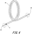
FIG. 4] FIG. 4 is a perspective view illustrating an outline of a torque transmittability evaluation testing method for a hollow stranded wire line for manipulation. - [
FIG. 5] FIG. 5 shows a graph in which a rotation angle on a proximal end side of a hollow stranded wire line for manipulation, and a rotation angle on the leading end side thereof at the same point of time are associated with each other. - The following will describe in detail the present invention based on preferred embodiments with reference where appropriate to the accompanying drawing.
-
FIG. 1 andFIG. 2 illustrate hollow stranded wire lines for manipulation (hereinafter, each of which is simply referred to also as hollow stranded wire line) according to different embodiments of the present invention. Each of the hollow strandedwire lines FIG. 1 andFIG. 2 . - The hollow stranded
wire line 2 shown inFIG. 1 has alayer 6 formed from sixwires 4, that is, has a stranded structure having one layer formed from six filament wires. The hollow strandedwire line 2 has a tunnel-shapedinternal space 8. - The hollow stranded
wire line 10 shown inFIG. 2 has two layers that are a lower layer (inner layer) 12 and an upper layer (outer layer) 14. Thelower layer 12 has a stranded structure, having sixwires 16, which has one layer formed from six filament wires. Theupper layer 14 has a stranded structure, having 12wires 18, which has one layer formed from 12 filament wires. The hollow strandedwire line 10 has a tunnel-shapedinternal space 20.Side wires 18 having different diameters are used for the hollow strandedwire line 10 such that the transverse cross-sectional shape becomes close to a circular shape.
However, theside wires 18 are not limited to such a structure, and all theside wires 18 may have an equal diameter. - The
wire wire lines wire lines - The hollow stranded wire line can be manufactured by using a stranding machine for wire ropes in a manner similar to a stranding manner for a wire rope. In this case, the following two manufacturing methods can be used. The first method is a method in which a preformed side wire, side strand, or the like is stranded along a circumference without inserting a core wire and a core strand. In the stranding process, the hollow stranded wire line is formed. Subsequently, the hollow stranded wire line is subjected to post heat treatment. The second method is a method in which a preformed side wire, side strand, or the like is stranded along a circumference in a state where a core wire or a core strand is inserted. In the stranding process, a wire rope is formed.
Subsequently, the wire rope is subjected to post heat treatment. After the wire rope is cut so as to have a predetermined length, the core wire or the core strand is extracted, to obtain the hollow stranded wire line. - A process for manufacturing the hollow stranded wire line will be briefly described below. Firstly, wires of the hollow stranded wire line are each adjusted in the wire drawing process step such that a required tensile strength can be obtained. Then, preforming is performed for the side wire or the side strand by a preformer in the wire stranding process step such that required forming rate and flatness can be obtained. In particular, the preforming is performed such that the spiral of the side wire or the side strand has a flattened transverse cross-section. The wires or strands are stranded by the stranding machine. In the case of a stranded wire line which does not include a core wire or a core strand (
FIG. 1 ,FIG. 2 ), a hollow stranded wire line is formed in the stranding process step. - In the post heat treatment process step for the hollow stranded wire line, not batch processing but continuous processing is performed. Specifically, the hollow stranded wire line, to be processed, which passes through a heat treatment furnace is tensioned at an inlet and an outlet of the heat treatment furnace. Thus, the straightness of the hollow stranded wire line is improved. Further, the forming rate and the flatness of the side wire or the side strand are determined. Thus, the hollow stranded wire line is completed.
- Meanwhile, in this manufacturing process, in a case where the stranded wire line includes a core wire or a core strand, a wire rope is completed. For example, as shown in
FIG. 3 , a 1+6 layer strandedwire rope 22 having onecore wire 24, and sixside wires 4 which form an outermost layer, is completed. Then, as described above, thewire rope 22 is cut so as to have a predetermined length, and thecore wire 24 is extracted, whereby the hollow strandedwire line 2 as shown in, for example,FIG. 1 is completed. - The hollow stranded
wire lines - In the present embodiment, the wire of the hollow stranded
wire line - A forming rate of the
side wire wire line FIG. 2 , friction between an inner layer and an outer layer is reduced, thereby further reducing energy loss in transmission of rotation of the hollow stranded wire line. It has been found that, by this action, transmission of rotational force from the proximal end to the leading end is facilitated, and torque transmittability is improved. Further, in a case where the forming rate is in the above-described range, also when a subject to be stranded does not include a core wire or a core strand, the side wire is less likely to be inserted into the internal space in the stranding process step using the stranding machine. - However, when the forming rate is not greater than 100%, a force toward the center of the hollow stranded wire line constantly acts on the side wire. Therefore, when the hollow stranded wire line is bent, the transverse cross-section tends to be deformed into an ellipsoidal shape. As a result, transmission of rotation of the hollow stranded wire line may be hindered. Further, in the case of the hollow stranded wire line having a plurality of layers as illustrated in
FIG. 2 , a friction between the inner layer and the outer layer is increased, and energy loss in transmission of rotation of the hollow stranded wire line may be thus increased. Further, in a case where a subject to be stranded does not include a core wire or a core strand, the side wire may be inserted into the internal space in the stranding process step. Meanwhile, when the forming rate is greater than 110%, a so-called open structure in which a gap is generated among the wires may be caused, and the diameter of the hollow stranded wire line may not be obtained as desired. In this viewpoint, the forming rate is preferably not less than 101% and preferably not greater than 105%. - The spiral of the side wire or the side strand is not completely circular but ellipsoidal or oval in some cases. In these cases, the spiral is a so-called flattened spiral. In this case, as the waviness diameter by which the forming rate is determined, the major axis among the major axis and the minor axis is used. Also when the major axis is used as the waviness diameter, the hollow stranded
wire line wire line - In the
side wire wire line - When the flatness is not less than 1.01, friction between the side wires or between the side strands is further increased, so that an effect of further reducing energy loss in transmission of rotation of the hollow stranded wire line is obtained. However, when the flatness is less than 1.01, this advantageous effect cannot be expected. Further, in the case of the hollow stranded wire line having a plurality of layers as shown in
FIG. 2 , when the flatness is less than 1.01, friction between an inner layer and an outer layer is increased, and energy loss in transmission of rotation of the hollow stranded wire line may be thus increased. Meanwhile, when the flatness is greater than 1.10, a so-called open structure is caused, and the hollow stranded wire line may be difficult to stably manufacture. In this viewpoint, the flatness is preferably not less than 1.01 and preferably not greater than 1.05. - As described above, when the forming rate of the side wire or the side strand is in the above-described range, flexibility, bendability, and transmittability of rotational force in the hollow stranded wire line are improved. In addition thereto, it has been found that, when the flatness is in the above-described range, flexibility, bendability, and transmittability of rotational force in the hollow stranded wire line are further improved.
- A strand angle of the
side wire wire line - Hereinafter, effects of the present invention will become apparent according to examples. However, the present invention should not be restrictively construed based on the description of examples.
- Hollow stranded wire lines, for manipulation, of examples 1 to 9 each having the structure shown in
FIG. 1 were obtained. Each of the hollow stranded wire lines was a hollow stranded wire line of wires for a medical device. A material of each of the wires was SUS304 austenitic stainless steel. The outer diameter (cord diameter) of the hollow stranded wire line was 0.7 mm. Firstly, a wire rope was manufactured, and a core wire was extracted from the wire rope, to manufacture the hollow stranded wire line. The outer diameter of the core wire of the wire rope during manufacturing of the hollow stranded wire line was 0.25mm. The outer diameter of the side wire was 0.23 mm. The side wire and the core wire each had the tensile strength of 2800 MPa. Each hollow stranded wire line had a stranded structure obtained by a core wire being extracted from the 1+6 layer stranded rope. A stranding pitch in each hollow stranded wire line was 5.5 mm. The temperature in the heat treatment for the hollow stranded wire line of each of examples 1 to 9 was 500°C. The forming rate and the flatness of the side wire of the hollow stranded wire line of each of examples 1 to 9 were as indicated in Table 1 and Table 2. - A hollow stranded wire line, for manipulation, of comparative example 1 was obtained in the same manner as in example 1 except that the forming rate and the flatness were as indicated in Table 2, and the cord diameter was much greater than 0.7 mm. As indicated in Table 2, the forming rate of the hollow stranded wire line of comparative example 1 was 115%, and a so-called open structure in which multiple gaps were generated among the wires, was thus caused. Therefore, the cord diameter was much greater than 0.7 mm. Such a hollow stranded wire line of comparative example 1 was not suitable as a hollow stranded wire line for manipulation in a medical device, and it was determined that this hollow stranded wire line was not able to be used as a hollow stranded wire line for manipulation in a medical device.
- Comparative example 2 was a hollow stranded wire line for manipulation according to conventional art. The hollow stranded wire line, for manipulation, of comparative example 2 was the same as in example 1 except that the forming rate and the flatness were as indicated in Table 2. The side wire of the hollow stranded wire line of comparative example 2 was not formed so as to be flattened.
-
Table 1 Evaluation of torque transmittability Ex. 1 Ex. 2 Ex. 3 Ex. 4 Ex. 5 Ex. 6 Forming rate (%) 100.5 105 101 101 101 101 Flatness 1.01 1.01 1.00 1.005 1.05 1.01 Torque transmittability (index) 59.0 30.3 56.5 45.2 21.5 19.7 -
Table 2 Evaluation of torque transmittability Ex. 7 Ex. 8 Ex. 9 Comp. Ex. 1 Comp. Ex. 2 Forming rate (%) 102 101 110 115 99 Flatness 1.02 1.10 1.01 1.01 1.00 Torque transmittability (index) 17.3 38.9 47.0 Not usable 100 - Torque transmittability is evaluated on the basis of difference, between a rotation angle on the proximal end side (corresponding to the operation unit of a medical instrument) and a rotation angle on the leading end side (corresponding to the treatment unit of the medical instrument), obtained when the proximal end side portion of each hollow stranded wire line was rotated. For the hollow stranded wire line of each of examples and comparative examples, the following torque transmittability evaluation test was performed.
- A dual spiral having the diameter of 200 mm was formed in the hollow stranded wire line of each of examples 1 to 9 and comparative examples 1, 2. As shown in
FIG. 4 , the dual spiral was formed by using a small-diameter pipe 26 which had a dual spiral shape having the diameter of 200 mm so as to be straight on both end sides. For example, a hollow strandedwire line 2 to be tested was inserted into the small-diameter pipe 26. A rotational force around the center axis was applied to aproximal end side 2A portion of the hollow strandedwire line 2 to be tested, in a state where the hollow strandedwire line 2 to be tested was inserted in the small-diameter pipe 26. While the rotational force was applied, a rotation angle on theproximal end side 2A of the hollow strandedwire line 2 and a rotation angle on aleading end side 2B thereof were simultaneously measured. -
FIG. 5 shows a graph in which the rotation angle on theproximal end side 2A of the hollow stranded wire line and the rotation angle on theleading end side 2B thereof at the same point of time are associated with each other. In other words,FIG. 5 is a graph indicating a relationship between an input rotation angle and an output rotation angle in the hollow stranded wire line for manipulation. The unit of the angle is degree (°). In the graph, a broken line that extends from the originating point of 0° so as to be tilted by 45° relative to the horizontal axis and the vertical axis represents a straight line that indicates that difference between the rotation angle on theproximal end side 2A and the rotation angle on theleading end side 2B is zero in a range of all the measured angles (range in which the input rotation angle is from 0° to about 720°). The difference, to be evaluated for the hollow stranded wire line to be tested, between the rotation angle on theproximal end side 2A and the rotation angle on theleading end side 2B is represented as difference in the vertical axis direction between the 45° titled straight line and the measured value curve in the drawing. The difference in the rotation angle corresponds to the rotation angle on the proximal end side. In the drawing, for easy understanding, the difference in the rotation angle is indicated so as to be greater than the actual one. In the range in which the input rotation angle is from 0° to 720°, the greatest angular difference among the measured differences in the rotation angle is evaluated. - The greatest angular difference in the hollow stranded wire line of each of examples 1 to 9 and comparative examples 1, 2 is indicated in Table 1 and Table 2 as an index with the greatest angular difference of comparative example 2 being 100. The less the greatest angular difference is, the less the value of the index is and the more excellent the torque transmittability is.
- As indicated in Table 1 and Table 2, the evaluation result clearly indicates that the present invention is superior.
- The hollow stranded wire line for manipulation according to the present invention is advantageously used as a hollow stranded wire line for manipulation in a medical instrument.
-
- 2, 10 ··· hollow stranded wire line for manipulation
- 4, 18 ··· side wire
- 6 ··· layer
- 8, 20 ··· internal space
- 12 ··· lower layer (inner layer)
- 14 ··· upper layer (outer layer)
- 16 ··· wire
- 22 ··· -wire rope
- 24 ··· core wire
- 26 ··· small-diameter pipe
Claims (4)
- A hollow stranded wire line for manipulation, the hollow stranded wire line comprising a side wire or a side strand which is an outermost layer, the side wire or the side strand having a forming rate that is greater than 100% and not greater than 110%.
- The hollow stranded wire line, for manipulation, according to claim 1, wherein the side wire or the side strand having been formed has a spiral shape in which a flatness that is an aspect ratio obtained by a major axis being divided by a minor axis is not less than 1.01 and not greater than 1.10.
- The hollow stranded wire line, for manipulation according to claim 1 or 2, wherein the forming rate is not less than 101% and not greater than 105%.
- The hollow stranded wire line, for manipulation, according to claim 2, wherein the flatness is not less than 1.01 and not greater than 1.05.
Applications Claiming Priority (2)
| Application Number | Priority Date | Filing Date | Title |
|---|---|---|---|
| JP2015170511A JP6611237B2 (en) | 2015-08-31 | 2015-08-31 | Hollow stranded wire for operation |
| PCT/JP2016/062748 WO2017038154A1 (en) | 2015-08-31 | 2016-04-22 | Hollow twisted wire for operation |
Publications (2)
| Publication Number | Publication Date |
|---|---|
| EP3293306A1 true EP3293306A1 (en) | 2018-03-14 |
| EP3293306A4 EP3293306A4 (en) | 2019-02-13 |
Family
ID=58187016
Family Applications (1)
| Application Number | Title | Priority Date | Filing Date |
|---|---|---|---|
| EP16841186.6A Withdrawn EP3293306A4 (en) | 2015-08-31 | 2016-04-22 | Hollow twisted wire for operation |
Country Status (6)
| Country | Link |
|---|---|
| US (1) | US10426505B2 (en) |
| EP (1) | EP3293306A4 (en) |
| JP (1) | JP6611237B2 (en) |
| KR (1) | KR20170136587A (en) |
| CN (1) | CN107614787A (en) |
| WO (1) | WO2017038154A1 (en) |
Cited By (2)
| Publication number | Priority date | Publication date | Assignee | Title |
|---|---|---|---|---|
| WO2021014098A1 (en) * | 2019-07-25 | 2021-01-28 | Compagnie Generale Des Etablissements Michelin | Method for separating and reassembling a dual layer assembly |
| US12036830B2 (en) | 2019-07-25 | 2024-07-16 | Compagnie Generale Des Etablissements Michelin | Highly compressible open reinforcing cord |
Families Citing this family (8)
| Publication number | Priority date | Publication date | Assignee | Title |
|---|---|---|---|---|
| JP5870226B1 (en) * | 2015-06-26 | 2016-02-24 | トクセン工業株式会社 | Rope for operation |
| JP5870227B1 (en) * | 2015-06-26 | 2016-02-24 | トクセン工業株式会社 | Rope for operation |
| JP6423374B2 (en) * | 2016-01-07 | 2018-11-14 | トクセン工業株式会社 | Hollow stranded wire for operation |
| JP6340447B1 (en) * | 2017-03-14 | 2018-06-06 | 株式会社三和テスコ | Sludge dewatering device attached to the belt conveyor water washing device |
| EP3636162B1 (en) * | 2018-10-09 | 2023-07-19 | BibbInstruments AB | Biopsy instrument and kit of parts |
| JP7347985B2 (en) * | 2019-08-05 | 2023-09-20 | トクセン工業株式会社 | Hollow stranded wire for electromagnetic shielding |
| CN113430848A (en) * | 2021-05-11 | 2021-09-24 | 盐城荣星制绳有限公司 | Production process of hollow steel wire rope |
| CN114214856B (en) * | 2021-11-01 | 2023-04-14 | 江阴法尔胜住电新材料有限公司 | Method for manufacturing composite steel strand |
Family Cites Families (17)
| Publication number | Priority date | Publication date | Assignee | Title |
|---|---|---|---|---|
| FR2533744A1 (en) | 1982-09-24 | 1984-03-30 | Thomson Jeumont Cables | Bearing neutral conductor for an electrical conductor bundle, method of manufacture and means of implementation. |
| JPS62170594A (en) * | 1986-01-17 | 1987-07-27 | 東京製綱株式会社 | Steel cord for reinforcing rubber |
| JPH0332555Y2 (en) * | 1987-10-16 | 1991-07-10 | ||
| JPH04281081A (en) * | 1991-03-06 | 1992-10-06 | Bridgestone Corp | Metallic cord for reinforcing rubber and tire using the same |
| JPH0663142A (en) | 1991-05-10 | 1994-03-08 | Kobe Steel Ltd | Pipe and catheter for diagnosis and treatment |
| JP2669754B2 (en) | 1991-12-27 | 1997-10-29 | 日本ケーブル・システム株式会社 | Operating rope |
| JPH08126648A (en) | 1994-11-02 | 1996-05-21 | Olympus Optical Co Ltd | Treatment instrument for endoscope |
| DE69517153T2 (en) | 1994-11-02 | 2001-02-01 | Olympus Optical Co., Ltd. | INSTRUMENT WORKING WITH ENDOSCOPE |
| US6881194B2 (en) | 2001-03-21 | 2005-04-19 | Asahi Intec Co., Ltd. | Wire-stranded medical hollow tube, and a medical guide wire |
| JP2002275774A (en) * | 2001-03-21 | 2002-09-25 | Asahi Intecc Co Ltd | Tube body for medical treatment, balloon catheter, and guide wire for medical treatment |
| JP3756086B2 (en) * | 2001-08-10 | 2006-03-15 | 朝日インテック株式会社 | Manufacturing method of medical guide wire |
| JP4704091B2 (en) * | 2005-04-05 | 2011-06-15 | 中央発條株式会社 | Wire rope and control cable |
| JP4497379B2 (en) * | 2006-08-23 | 2010-07-07 | 朝日インテック株式会社 | Medical treatment tool |
| JP4609903B2 (en) | 2008-03-24 | 2011-01-12 | 朝日インテック株式会社 | Medical guidewire |
| JP2011006803A (en) * | 2009-06-24 | 2011-01-13 | Hi-Lex Corporation | Inner cable for transmitting rotating torque, and control cable and door-opening and closing mechanism, using the same |
| JP2011202321A (en) * | 2010-03-26 | 2011-10-13 | Sumitomo Denko Steel Wire Kk | Ring-form metal cord, endless metal belt and method for producing ring-form metal cord |
| JP2012082530A (en) * | 2010-10-06 | 2012-04-26 | Sumitomo Denko Steel Wire Kk | Annular metal cord, endless metal belt having the same and method for manufacturing the same |
-
2015
- 2015-08-31 JP JP2015170511A patent/JP6611237B2/en active Active
-
2016
- 2016-04-22 KR KR1020177032357A patent/KR20170136587A/en active Search and Examination
- 2016-04-22 CN CN201680029896.3A patent/CN107614787A/en active Pending
- 2016-04-22 EP EP16841186.6A patent/EP3293306A4/en not_active Withdrawn
- 2016-04-22 US US15/580,209 patent/US10426505B2/en active Active
- 2016-04-22 WO PCT/JP2016/062748 patent/WO2017038154A1/en active Application Filing
Cited By (6)
| Publication number | Priority date | Publication date | Assignee | Title |
|---|---|---|---|---|
| WO2021014098A1 (en) * | 2019-07-25 | 2021-01-28 | Compagnie Generale Des Etablissements Michelin | Method for separating and reassembling a dual layer assembly |
| FR3099192A1 (en) * | 2019-07-25 | 2021-01-29 | Compagnie Generale Des Etablissements Michelin | Process for splitting and reassembling a two-layer assembly |
| CN114423898A (en) * | 2019-07-25 | 2022-04-29 | 米其林集团总公司 | Method for separating and reassembling double-layer components |
| CN114423898B (en) * | 2019-07-25 | 2024-02-23 | 米其林集团总公司 | Method for separating and reassembling a double-layer assembly |
| US12006626B2 (en) | 2019-07-25 | 2024-06-11 | Compagnie Generale Des Etablissements Michelin | Method for separating and reassembling a dual layer assembly |
| US12036830B2 (en) | 2019-07-25 | 2024-07-16 | Compagnie Generale Des Etablissements Michelin | Highly compressible open reinforcing cord |
Also Published As
| Publication number | Publication date |
|---|---|
| EP3293306A4 (en) | 2019-02-13 |
| CN107614787A (en) | 2018-01-19 |
| WO2017038154A1 (en) | 2017-03-09 |
| US20180161053A1 (en) | 2018-06-14 |
| JP6611237B2 (en) | 2019-11-27 |
| KR20170136587A (en) | 2017-12-11 |
| JP2017048471A (en) | 2017-03-09 |
| US10426505B2 (en) | 2019-10-01 |
Similar Documents
| Publication | Publication Date | Title |
|---|---|---|
| US10426505B2 (en) | Hollow stranded wire line for manipulation | |
| EP3290580B1 (en) | Manipulation rope | |
| EP3312338B1 (en) | Manipulation rope | |
| CN105983168B (en) | Catheter tube | |
| CN104857613A (en) | Guide wire | |
| EP1243283A3 (en) | A wire-stranded hollow tube, a medical tube body and a medical guide wire | |
| EP2881136B1 (en) | Guidewire | |
| JP6665150B2 (en) | Hollow stranded wire | |
| EP2921195A1 (en) | Guide wire | |
| WO2014185527A1 (en) | Process for manufacturing aluminum electric wire | |
| JP2012146591A (en) | Multicore cable, and method of manufacturing the same | |
| JP5999708B2 (en) | Coil body, guide wire including coil body, catheter, and medical treatment instrument | |
| JP6596470B2 (en) | Medical treatment device wire and guide wire | |
| JP2007330288A (en) | Core material or guide wire composed of core material and its manufacturing method | |
| JP6616811B2 (en) | Medical device operation rope | |
| US20160035459A1 (en) | Multi-core cable and method of manufacturing the same | |
| JP6423374B2 (en) | Hollow stranded wire for operation | |
| JP2024055265A (en) | Operation rope | |
| JP2016221231A (en) | Guide wire | |
| JP2019180839A (en) | Method for manufacturing medical coil, medical coil, method for manufacturing endoscope treatment tool and endoscope treatment tool | |
| JP2022190735A (en) | coil body |
Legal Events
| Date | Code | Title | Description |
|---|---|---|---|
| PUAI | Public reference made under article 153(3) epc to a published international application that has entered the european phase |
Free format text: ORIGINAL CODE: 0009012 |
|
| 17P | Request for examination filed |
Effective date: 20171206 |
|
| AK | Designated contracting states |
Kind code of ref document: A1 Designated state(s): AL AT BE BG CH CY CZ DE DK EE ES FI FR GB GR HR HU IE IS IT LI LT LU LV MC MK MT NL NO PL PT RO RS SE SI SK SM TR |
|
| AX | Request for extension of the european patent |
Extension state: BA ME |
|
| DAV | Request for validation of the european patent (deleted) | ||
| DAX | Request for extension of the european patent (deleted) | ||
| A4 | Supplementary search report drawn up and despatched |
Effective date: 20190114 |
|
| RIC1 | Information provided on ipc code assigned before grant |
Ipc: F16C 1/20 20060101ALI20190108BHEP Ipc: A61B 17/00 20060101ALI20190108BHEP Ipc: F16C 1/02 20060101ALI20190108BHEP Ipc: D07B 1/12 20060101AFI20190108BHEP Ipc: D07B 1/06 20060101ALI20190108BHEP |
|
| STAA | Information on the status of an ep patent application or granted ep patent |
Free format text: STATUS: EXAMINATION IS IN PROGRESS |
|
| 17Q | First examination report despatched |
Effective date: 20200513 |
|
| STAA | Information on the status of an ep patent application or granted ep patent |
Free format text: STATUS: THE APPLICATION IS DEEMED TO BE WITHDRAWN |
|
| 18D | Application deemed to be withdrawn |
Effective date: 20200924 |