JP2012082530A - Annular metal cord, endless metal belt having the same and method for manufacturing the same - Google Patents
Annular metal cord, endless metal belt having the same and method for manufacturing the same Download PDFInfo
- Publication number
- JP2012082530A JP2012082530A JP2010226797A JP2010226797A JP2012082530A JP 2012082530 A JP2012082530 A JP 2012082530A JP 2010226797 A JP2010226797 A JP 2010226797A JP 2010226797 A JP2010226797 A JP 2010226797A JP 2012082530 A JP2012082530 A JP 2012082530A
- Authority
- JP
- Japan
- Prior art keywords
- core
- annular
- strand material
- side wire
- strand
- Prior art date
- Legal status (The legal status is an assumption and is not a legal conclusion. Google has not performed a legal analysis and makes no representation as to the accuracy of the status listed.)
- Pending
Links
Images


Classifications
-
- D—TEXTILES; PAPER
- D07—ROPES; CABLES OTHER THAN ELECTRIC
- D07B—ROPES OR CABLES IN GENERAL
- D07B1/00—Constructional features of ropes or cables
- D07B1/06—Ropes or cables built-up from metal wires, e.g. of section wires around a hemp core
- D07B1/0673—Ropes or cables built-up from metal wires, e.g. of section wires around a hemp core having a rope configuration
- D07B1/0686—Ropes or cables built-up from metal wires, e.g. of section wires around a hemp core having a rope configuration characterised by the core design
-
- D—TEXTILES; PAPER
- D07—ROPES; CABLES OTHER THAN ELECTRIC
- D07B—ROPES OR CABLES IN GENERAL
- D07B7/00—Details of, or auxiliary devices incorporated in, rope- or cable-making machines; Auxiliary apparatus associated with such machines
- D07B7/16—Auxiliary apparatus
- D07B7/165—Auxiliary apparatus for making slings
-
- D—TEXTILES; PAPER
- D07—ROPES; CABLES OTHER THAN ELECTRIC
- D07B—ROPES OR CABLES IN GENERAL
- D07B2201/00—Ropes or cables
- D07B2201/10—Rope or cable structures
- D07B2201/1012—Rope or cable structures characterised by their internal structure
- D07B2201/1014—Rope or cable structures characterised by their internal structure characterised by being laid or braided from several sub-ropes or sub-cables, e.g. hawsers
-
- D—TEXTILES; PAPER
- D07—ROPES; CABLES OTHER THAN ELECTRIC
- D07B—ROPES OR CABLES IN GENERAL
- D07B2201/00—Ropes or cables
- D07B2201/20—Rope or cable components
- D07B2201/2047—Cores
- D07B2201/2052—Cores characterised by their structure
-
- D—TEXTILES; PAPER
- D07—ROPES; CABLES OTHER THAN ELECTRIC
- D07B—ROPES OR CABLES IN GENERAL
- D07B7/00—Details of, or auxiliary devices incorporated in, rope- or cable-making machines; Auxiliary apparatus associated with such machines
- D07B7/02—Machine details; Auxiliary devices
- D07B7/025—Preforming the wires or strands prior to closing
Abstract
Description
本発明は、環状金属コード、無端金属ベルト及び環状金属コードの製造方法に関するものである。 The present invention relates to an annular metal cord, an endless metal belt, and a method for producing an annular metal cord.
従来、環状金属コードを製造する方法として、例えば特許文献1,2に記載されているように、ワイヤーロープを構成するストランド材の半分を解撚または切除して取り除いた後に、残ったストランド材を一部環状にしつつその周囲に巻き付けてエンドレス加工することが知られている。
Conventionally, as a method of manufacturing an annular metal cord, for example, as described in
特許文献1に記載されたワイヤーロープの簡易エンドレス加工法は、まず、設計寸法リングの内周長の2倍強の長さをもった6本の素線が撚り合されて構成されたワイヤーロープを用意する。これを3本の素線の撚り合せ線2本に解き別けて内周長と当該内周長より少し長いより代とを有する基糸を形成する。次に、当該3本素線撚り合せ線からなる基糸の一方を用いて、まず設計寸法の基本となるリング部とその組み合わせ部から延出するストランド部を形成する。そのうえ、当該延出するストランド部をリング部に撚り合せながら巻き付けて2本の基糸(6本の素線)が撚り合された状態のエンドレス加工を行う。その後、基糸の撚り合せ端部をロック止めもしくは半かご差しまたは半かご差しとロック止めの組み合わせ処理のいずれかの端部処理をする。
The wire rope simple endless processing method described in
特許文献2に記載されたエンドレススリングは、次のようにして製造されている。まず、所定長さのワイヤーロープの全長にわたって、全本数の1/2のストランドを切除し、ワイヤーロープの全長の1/2の心綱を切除する。残った心綱の両端部を同心に突き合わせたうえ、心綱を切除した側のストランドを、心綱を切除しない側のストランドの切除部に巻き付けて同心状のエンドレスとする。その後、心綱及びストランドの両端部にまたがってスリーブを圧縮加工する。 The endless sling described in Patent Document 2 is manufactured as follows. First, a half of the total number of strands is cut out over the entire length of the wire rope of a predetermined length, and a heart rope of 1/2 of the total length of the wire rope is cut out. The both ends of the remaining heart rope are concentrically butted, and the strand on the side where the heart rope is cut is wound around the cut portion of the strand on which the heart rope is not cut to make a concentric endless. Thereafter, the sleeve is compressed over both ends of the cord and the strand.
特許文献3に記載されたエンドレスリングは、ワイヤーロープの一部を輪状に交差させて輪状部を形成し、ワイヤーロープを前記輪状部の回りに撚り合わせながら所定の回数周回させた後、ワイヤーロープの残り部分を撚り合わせた部分の内部にロープ心として入れ込んで形成する。 The endless ring described in Patent Document 3 forms a ring-shaped part by intersecting a part of the wire rope in a ring shape, and after turning the wire rope around the ring-shaped part a predetermined number of times, the wire rope It is formed by inserting a rope core into the twisted portion of the remaining portion.
特許文献4に記載された環状金属コードは、複数のストランド材同士を撚り合わせた金属コードが解撚されて合計断面積の異なる2つの線材群に分けられ、合計断面積の大きい方のストランド材の群を再使用線材群とし、合計断面積の小さい方のストランド材の群を不使用線材群として、再使用線材群の内の1本のストランド材が、複数周回環状にされつつその環状部分における再使用線材の内の他のストランド材及び不使用線材群の抜けた螺旋状の空隙部に余長部が嵌め入れられて巻き付けられている。 The annular metal cord described in Patent Document 4 is divided into two wire rod groups having different total cross-sectional areas by untwisting a metal cord obtained by twisting a plurality of strand materials, and has a larger total cross-sectional area. A group of strands having a smaller total cross-sectional area as a group of unused wires, and one strand of the group of reused wires being formed into a plurality of loops, The extra length portion is fitted and wound around the spiral void portion from which the other strand material and unused wire group in the reusable wire rod in FIG.
特許文献1,2に記載の環状金属コードは、何れも玉掛け用吊り具であり、所定の曲げや張力などの負荷を繰り返し受けるような使用状況は想定されていないものである。これらの環状金属コードは、ワイヤーロープを横断面でみて円周上のストランド材の本数を一旦半分にして、残ったストランド材の余長を空いている残り半分のスペースに再巻き付けしているものであるため、隣り合うストランド材同士の接触抵抗が弱い。そのため、前記のような繰り返し負荷が加わると撚り緩みが生じやすく、そのまま使用を続けていると最後には破断してしまう。
Each of the annular metal cords described in
さらに、環状に巻き付けた後の端末処理は、特許文献1では端末を撚り合わせた箇所に差し込むかご差しやロック止めであるため、前記のような繰り返し負荷が加わるとこれらの箇所に応力集中が起こり、早期に破断してしまう。また、特許文献2ではスリーブにより両端末を固定するため、その部分だけコード径が太くなり、荷重が環状方向で不均一になる。このように、特許文献1,2に記載の環状金属コードは、継続的な繰り返し負荷に対して耐え得る構造ではない。
Further, since the terminal treatment after the annular winding is a cage insertion or locking by inserting the terminal into the place where the terminal is twisted in
特許文献3に記載の環状金属コードであるエンドレスリングは、ワイヤーロープを輪状部の回りに撚り合わせながら所定の回数周回させることにより、ワイヤーロープ全体を使用して巻き付けることになるが、この場合巻き付けピッチが一巻き毎にばらついてしまい、コード径が太くなり、環状方向で均一な強度が得られない。また、このエンドレスリングも、荷吊り作業に用いられるものであり、所定の曲げや張力などの負荷を繰り返し受けるような使用状況は想定されていないものである。 The endless ring, which is an annular metal cord described in Patent Document 3, is wound using the entire wire rope by winding the wire rope a predetermined number of times while twisting around the ring-shaped portion. The pitch varies for each turn, the cord diameter becomes thick, and a uniform strength cannot be obtained in the annular direction. Further, this endless ring is also used for a load lifting operation, and is not assumed to be used in a state where it repeatedly receives loads such as predetermined bending and tension.
これらのような環状金属コードを無端金属ベルトに用いると、撚り緩みや端末の結合部などの影響で回転負荷が変動し、比較的短期間で破損してしまうおそれがある。 When such an annular metal cord is used for an endless metal belt, the rotational load fluctuates due to the effects of loosening of the twist, the joint portion of the terminal, and the like, and there is a risk of breakage in a relatively short period of time.
また、特許文献4に記載の環状金属コードは、環状のコア部分が無いので、量産する際には個々の環状金属コードの環状径のばらつきが発生することが懸念される。 Moreover, since the cyclic | annular metal cord of patent document 4 does not have a cyclic | annular core part, when mass-producing, it is anxious about the dispersion | variation in the cyclic | annular diameter of each cyclic | annular metal cord generate | occur | produced.
そこで、本発明の目的は、継続的な繰り返し負荷に対しても撚り緩みが生じず巻き付けた形状を維持することができるとともに、環状径のばらつきを抑制することのできる環状金属コード、無端金属ベルト及び環状金属コードの製造方法を提供することにある。 Accordingly, an object of the present invention is to provide an annular metal cord and an endless metal belt capable of maintaining a wound shape without twisting and loosening even with continuous repetitive loads, and capable of suppressing variations in annular diameter. And it is providing the manufacturing method of a cyclic | annular metal cord.
上記課題を解決することのできる本発明に係る環状金属コードは、複数本のコア用ストランド材が撚り合わされたコア用原コードが解撚され、1本の前記コア用ストランド材が、環状にされつつ他のコア用ストランド材の抜けた螺旋状の空隙部に嵌め入れられて環状コアとして形成され、
少なくとも6本の側線用ストランド材が撚り合わされた側線用原コードを解撚した側線用ストランド材が、前記環状コアの周りに環状に複数周巻き付けられるとともに、他の側線用ストランド材の抜けた螺旋状の空隙部に螺旋状に巻き付けられていることを特徴とする。
In the annular metal cord according to the present invention that can solve the above-mentioned problems, the core core cord in which a plurality of core strand materials are twisted together is untwisted, and one core strand material is formed into an annular shape. While being inserted into the spiral void portion from which the other strand material for the core is removed, it is formed as an annular core,
A side wire strand material obtained by untwisting a side wire original cord in which at least six side wire strand materials are twisted together is wound around the annular core in a plurality of circles, and a spiral from which other side wire strand materials are removed. It is characterized by being wound in a spiral shape around the gap.
このような構成の環状金属コードによれば、環状コアが設けられているので、環状金属コードの環状径が環状コアによって決まり、量産する際にも個々の環状金属コードの環状径のばらつきが発生することを抑制できる。また、コア用原コードを解撚して得られた1本のコア用ストランド材を用いて、他のコア用ストランド材の抜けた螺旋状の空隙部に嵌め入れられて環状コアが形成されているので、コア用ストランド材同士の接触抵抗によって環状コアの形状が安定しやすく、環状金属コードの形状も安定する。
また、環状コアの周りには、側線用ストランド材が環状に複数周巻き付けられ、他の側線用ストランド材の抜けた螺旋状の空隙部に螺旋状に巻き付けられているので、側線用ストランド材同士の接触抵抗によって環状金属コードの形状も安定する。隣り合う側線用ストランド材同士の接触抵抗が得られ、側線用ストランド材の全長に亘って側線用ストランド材同士が拘束されるため、繰り返し負荷が加わっても撚り緩みが生じにくい。また、側線用ストランド材同士の接触抵抗によって巻き付け状態が維持されるため、端末処理を簡素なものにすることができる。
According to the annular metal cord having such a configuration, since the annular core is provided, the annular diameter of the annular metal cord is determined by the annular core, and variation in the annular diameter of each annular metal cord occurs even in mass production. Can be suppressed. Further, an annular core is formed by using one core strand material obtained by untwisting the core core cord, and being fitted into a spiral void portion from which another core strand material is removed. Therefore, the shape of the annular core is easily stabilized by the contact resistance between the core strand materials, and the shape of the annular metal cord is also stabilized.
In addition, a plurality of side wire strand materials are wound around the annular core in a ring shape, and are spirally wound around the spiral void portion from which the other side wire strand material is removed. The shape of the annular metal cord is also stabilized by the contact resistance. Contact resistance between adjacent side wire strand materials is obtained, and the side wire strand materials are constrained over the entire length of the side wire strand material, so that twisting and loosening hardly occur even when a repeated load is applied. Moreover, since a winding state is maintained by the contact resistance between the strand materials for side wires, the terminal treatment can be simplified.
本発明に係る環状金属コードにおいて、前記環状コアのコア用ストランド材の両端余長部が、他のコア用ストランド材の抜けた螺旋状の空隙部に嵌め入れられて巻き付けられていることが好ましい。
これにより、コア用ストランド材の両端余長部がコア用ストランド材同士の接触抵抗によって拘束され、環状コアにおけるコア用ストランド材の巻き緩みが生じにくい。
In the annular metal cord according to the present invention, it is preferable that the extra length portions of both ends of the core strand material of the annular core are fitted into and wound around the spiral void portion from which the other core strand material is removed. .
As a result, both end surplus portions of the core strand material are constrained by the contact resistance between the core strand materials, and the winding of the core strand material in the annular core hardly occurs.
本発明に係る環状金属コードにおいて、前記環状コアのコア用ストランド材の一部が樹脂繊維であることが好ましい。
コア用ストランド材に樹脂繊維が含まれることにより、環状コアにおけるコア用ストランド材の摩擦抵抗が増加し、環状コアに引張り張力が加わってもコア用ストランド材同士が滑って巻き付けが緩んでしまうことを防止できる。また、環状コアと側線用ストランド材との摩擦抵抗も増加するので、環状金属コードの形状も安定する。
そして、その樹脂繊維がアラミド繊維であることが更に好ましい。アラミド繊維を用いることで、抗張力も良好である。
In the annular metal cord according to the present invention, it is preferable that a part of the core strand material of the annular core is a resin fiber.
By including resin fibers in the core strand material, the frictional resistance of the core strand material in the annular core increases, and even when tensile tension is applied to the annular core, the core strand material slips and loosens the winding. Can be prevented. Moreover, since the frictional resistance between the annular core and the side wire strand material is increased, the shape of the annular metal cord is also stabilized.
The resin fiber is more preferably an aramid fiber. By using an aramid fiber, the tensile strength is also good.
本発明に係る環状金属コードにおいて、前記環状コアのコア用ストランド材と前記側線用ストランド材の撚り方向が同一方向であることが好ましい。
これにより、環状コアの周りに螺旋状に複数周回巻き付けられた側線用ストランド材の余長を、側線用ストランド材同士の螺旋状の隙間から環状コアに向けて嵌め込んで収容する際、コア用ストランド材の撚り方向に沿って嵌め込むことができ、嵌め込んだ部分の形状も安定しやすい。
In the annular metal cord according to the present invention, it is preferable that the twisting direction of the core strand material of the annular core and the side wire strand material is the same direction.
Thereby, when the extra length of the side wire strand material spirally wound around the annular core is fitted and accommodated from the spiral gap between the side wire strand materials toward the annular core, the core is used. It can be fitted along the twisting direction of the strand material, and the shape of the fitted part is easy to be stabilized.
また、本発明に係る無端金属ベルトは、上記本発明に係る環状金属コードを備えていることが好ましい。
上述の環状金属コードを用いることによって、継続的な繰り返し負荷に対しても環状金属コードの撚り緩みが生じず形状を維持することができるため、破断強度及び耐疲労性に優れた無端金属ベルトを得ることができる。さらに、個々の環状金属コードの環状径のばらつきが少ないため、環状金属コードを複数本用いて無端金属ベルトとする場合に、荷重のばらつきが少なく抑えられ、安定したベルトの走行性が得られ、長寿命化も図ることができる。
The endless metal belt according to the present invention preferably includes the annular metal cord according to the present invention.
By using the above-mentioned annular metal cord, the endless metal belt excellent in breaking strength and fatigue resistance can be maintained because the shape of the annular metal cord can be maintained without twisting and loosening even with continuous repeated loads. Obtainable. Furthermore, since there is little variation in the annular diameter of individual annular metal cords, when using an endless metal belt using a plurality of annular metal cords, variation in load is suppressed to a low level, and stable belt travelability is obtained. Long service life can also be achieved.
また、上記課題を解決することのできる本発明に係る環状金属コードの製造方法は、複数本のコア用ストランド材が撚り合わされたコア用原コードを解撚し、1本の前記コア用ストランド材を、環状にしつつ他のコア用ストランド材の抜けた螺旋状の空隙部に嵌め入れて環状コアとして形成し、
少なくとも6本の側線用ストランド材が撚り合わされた側線用原コードを解撚した側線用ストランド材を、前記環状コアの周りに環状に複数周巻き付けるとともに、他の側線用ストランド材の抜けた螺旋状の空隙部に螺旋状に巻き付けることを特徴とする。
Moreover, the manufacturing method of the cyclic | annular metal cord which concerns on this invention which can solve the said subject untwists the core original cord by which the strand material for several cores was twisted together, and one said strand material for cores Is formed into an annular core by being fitted into a spiral void portion from which other core strand materials are removed while being annular.
A side wire strand material obtained by untwisting a side wire original cord in which at least six side wire strand materials are twisted together is wound around the annular core in a plurality of circles, and a spiral shape from which other side wire strand materials are removed. It is characterized in that it is wound in a spiral shape around the gap portion.
このような構成の環状金属コードの製造方法によれば、環状コアを設けているので、環状金属コードの環状径が環状コアによって決まり、量産する際にも個々の環状金属コードの環状径のばらつきが発生することを抑制できる。また、コア用原コードを解撚して得られた1本のコア用ストランド材を用いて、他のコア用ストランド材の抜けた螺旋状の空隙部に嵌め入れて環状コアを形成するので、コア用ストランド材同士の接触抵抗によって環状コアの形状が安定しやすく、環状金属コードの形状も安定する。
また、環状コアの周りには、側線用ストランド材を環状に複数周巻き付け、他の側線用ストランド材の抜けた螺旋状の空隙部に螺旋状に巻き付けるので、側線用ストランド材同士の接触抵抗によって環状金属コードの形状も安定する。隣り合う側線用ストランド材同士の接触抵抗が得られ、側線用ストランド材の全長に亘って側線用ストランド材同士が拘束されるため、繰り返し負荷が加わっても撚り緩みが生じにくい。また、側線用ストランド材同士の接触抵抗によって巻き付け状態が維持されるため、端末処理を簡素なものにすることができる。
According to the manufacturing method of the annular metal cord having such a configuration, since the annular core is provided, the annular diameter of the annular metal cord is determined by the annular core, and variation in the annular diameter of individual annular metal cords even in mass production Can be prevented from occurring. In addition, since one core strand material obtained by untwisting the core original cord is inserted into the spiral void portion from which the other core strand material is removed, an annular core is formed. The shape of the annular core is easily stabilized by the contact resistance between the core strand materials, and the shape of the annular metal cord is also stabilized.
Also, around the annular core, a plurality of side wire strand materials are wound in a ring shape and wound in a spiral space where other side wire strand materials are removed, so that the contact resistance between the side wire strand materials The shape of the annular metal cord is also stable. Contact resistance between adjacent side wire strand materials is obtained, and the side wire strand materials are constrained over the entire length of the side wire strand material, so that twisting and loosening hardly occur even when a repeated load is applied. Moreover, since a winding state is maintained by the contact resistance between the strand materials for side wires, the terminal treatment can be simplified.
本発明によれば、継続的な繰り返し負荷に対しても撚り緩みが生じず巻き付けた形状を維持することができ、環状径のばらつきを抑制することもできる環状金属コード、無端金属ベルト及び環状金属コードの製造方法を提供することができる。したがって、本発明の環状金属コード及び無端金属ベルトを産業機械に用いれば、当該産業機械を耐久性に優れかつ高品質のものとすることができる。 According to the present invention, an annular metal cord, an endless metal belt, and an annular metal that can maintain a wound shape without causing twist loosening even for continuous repeated loads, and can also suppress variation in the annular diameter. A method for manufacturing a code can be provided. Therefore, when the annular metal cord and the endless metal belt of the present invention are used in an industrial machine, the industrial machine can be excellent in durability and high quality.
以下、添付図面を参照して、本発明の好適な実施形態について詳細に説明する。なお、説明において、同一要素又は同一機能を有する要素には、同一符号を用いることとし、重複する説明は省略する。 Hereinafter, preferred embodiments of the present invention will be described in detail with reference to the accompanying drawings. In the description, the same reference numerals are used for the same elements or elements having the same function, and redundant description is omitted.
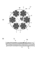
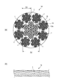
図1は本実施形態に係る環状金属コードの斜視図であり、図2(a)は環状金属コードを示す径方向の断面図であり、同図(b)は環状金属コードの側面図である。
図1及び図2に示すように、環状金属コードC1は、ストランド材を複数本用いて環状に撚り合わせてなるものであって、ストランド材として予め複数の金属素線が撚り合わされた側線用ストランド材1を用いている。
FIG. 1 is a perspective view of an annular metal cord according to the present embodiment, FIG. 2A is a radial sectional view showing the annular metal cord, and FIG. 1B is a side view of the annular metal cord. .
As shown in FIGS. 1 and 2, the annular metal cord C1 is formed by twisting a plurality of strand materials into a ring shape, and a strand for side wires in which a plurality of metal strands are twisted in advance as a strand material.
本実施形態の環状金属コードC1は、予め螺旋状にくせ付けされた1本の側線用ストランド材1を用意し、この側線用ストランド材1を、環状コア11(図2(a)参照)の周囲に、複数周回(本例では6周)巻き付けて形成されている。巻き付けの撚り方向は、例えばZ撚である。この環状金属コードC1を側線用ストランド1の径方向の断面で見ると、6本の側線用ストランド材1が円周状に配置され、その内側に環状コア11のコア用ストランド材12が収容された構造を有している。
The annular metal cord C1 of the present embodiment prepares one side
各側線用ストランド材1は、7本の金属素線10がS撚方向で撚り合わされて(下撚りされて)ストランド材10aとされ、このストランド材10aを7本S撚方向で撚り合わされて(中撚りされて)構成されている。
金属素線10は、例えば、炭素(C)を0.7質量%以上含む高炭素鋼ワイヤからなるものである。0.70質量%以上のCを含む材料を選定することで、金属素線10をより破断強度に優れた鋼線とすることができる。また、金属素線10の表面には、銅合金(例えば、真鍮)または亜鉛のめっき処理が施されていてもよい。なお、金属素線10の材質は、前記のものに限られず、例えば、ピアノ線でもよい。
In each side
The
また、金属素線10の直径は0.03mm以上0.30mm以下の範囲内である。
直径が0.03mm以上0.30mm以下の金属素線10で側線用ストランド材1を形成し、側線用ストランド材1の直径型付け率を金属素線10の直径に適した程度に調整することで、しなやかで適度な螺旋形状を有する側線用ストランド材1を得ることができる。よって、側線用ストランド材1の巻き付けが容易となり、かつ巻き付け後の巻き緩みが生じにくくなる。
Moreover, the diameter of the
By forming the side
なお、直径型付率は、環状金属コードC1の断面直径(1本の側線用ストランド材1が複数周回空隙部に嵌め入れられて6本の側線用ストランド材1が円周状に配置された断面の直径)をDとし、型付けされた側線用ストランド材1の波高さ(自己径含む)をHとすると、「直径型付率(%)=H/D×100」で表される。
It should be noted that the diameter ratio is the cross-sectional diameter of the annular metal cord C1 (one side
側線用ストランド材1同士は、Z撚、つまり側線用ストランド材1を構成する金属素線10の撚り方向とは逆方向に巻き付けられる。すなわち、側線用ストランド材1は、予めZ撚方向の螺旋状にくせ付けされている。一方、側線用ストランド材1自身は、金属素線10をS撚したストランド材10aをさらにS撚した構成であるため、環状金属コードC1はS/S撚構造とZ巻構造を組み合わせたものとなる。金属素線10の撚り方向と、側線用ストランド材1の巻き付け方向とが逆であると、環状金属コードC1の機械的特性に方向性が生じることが抑制されて捩れにくく、表面外観に凹凸の少ない環状金属コードC1を得ることができる。また、環状金属コードC1を環状方向に沿って回転させて使用する場合でも蛇行しにくくなる。
The side
また、側線用ストランド材1は、環状金属コードC1の外周に配置された6本の撚り合わせ中心軸に対して所定の巻き付け角度で巻き付けられている。このため、側線用ストランド材1が乱れなく巻かれ、表面状態が略均一な環状金属コードC1を得ることができる。本実施形態においては、図2(b)に示すように、X方向、すなわち環状金属コードC1の中心軸が延びる方向に対する側線用ストランド材1の巻き付け角度θは、4.5度以上17.0度以下となっている。巻き付け角度θを4.5度以上とすることで、側線用ストランド材1の巻き緩みが生じにくくなる。巻き付け角度θを17.0度以下とすることで、側線用ストランド材1の伸度が過度に大きくなることを防ぐことができる。つまり、側線用ストランド材1の巻き付け角度θを4.5度以上17.0度以下とすることで、適度な伸度を有し、かつしなやかな環状金属コードC1を得ることができる。
Further, the side
環状コア11は、予め螺旋状にくせ付けされた1本のコア用ストランド材12を用意し、このコア用ストランド材12を所定の環状径で1周または2周(本例では1周)巻き付けた後、さらに、その環状にした部分のコア用ストランド材12の螺旋状の空隙部に両端の余長部を嵌め入れて巻き付けたものである。この環状コア11は、コア用ストランド材12の余長部が、コア用ストランド材12自身の螺旋状の空隙部に入り込むように巻き付けられているため、環状径が所定の寸法に安定する。
For the
環状コア11を構成するコア用ストランド材12は、複数本の金属素線を撚り合わせてなるものであり、例えば3本の金属素線12aを撚り合わせたストランド材12bを3本用意し、更にそれら3本を撚り合わせて構成されている。
コア用ストランド材12を構成する金属素線12aは、側線用ストランド材1と同様の材質のものを使用でき、その線径も同等もしくは若干異なるものを使用できる。
The
The
コア用ストランド材12を構成する素線の一部が樹脂繊維からなるものであってもよい。例えば、ストランド材12bの1本が、樹脂繊維を束ねたものに置換されているものでもよい。コア用ストランド材12に樹脂繊維が含まれることにより、環状コア11におけるコア用ストランド材12の摩擦抵抗が増加し、環状コア11に引張り張力が加わってもコア用ストランド材12同士が滑って巻き付けが緩んでしまうことを防止できる。また、環状コア11と側線用ストランド材1との摩擦抵抗も増加するので、環状金属コードC1の形状も安定する。コア用ストランド材12に用いる樹脂繊維としては、アラミド繊維を例示できる。アラミド繊維を用いると抗張力が良好であり、他のストランド材12bや側線用ストランド材1との摩擦抵抗が増加するので好ましい。
A part of the strands constituting the
図3は、側線用ストランド材1の余長部を、側線用ストランド材1を巻き付けた内側に収容した箇所の断面図である。
環状コア11は、螺旋状にくせ付けされたコア用ストランド材12を環状にしたものであるので、その環状方向に沿った螺旋形状を有するとともに、螺旋状の空隙部を有する。環状コア11の周囲に巻き付けられた側線用ストランド材1の両端の余長部は、巻き付けられた側線用ストランド材1同士の隙間から、環状コア11の空隙部に落とし込まれ、環状コア11とともに内部に収容されている。その際、環状コア11のコア用ストランド材12と側線用ストランド材1の撚り方向が同一方向であることが好ましい。例えば、側線用ストランド材1は予めZ撚方向の螺旋状にくせ付けされ、Z撚で巻き付けられている場合には、コア用ストランド材12も予めZ撚方向の螺旋状にくせ付けされたものであるとよい。これにより、環状コア11の周りに螺旋状に複数周回巻き付けられた側線用ストランド材1の余長を、側線用ストランド材1同士の螺旋状の隙間から環状コア11に向けて嵌め込んで収容する際、コア用ストランド材12の撚り方向に沿って嵌め込むことができ、嵌め込んだ部分の形状も安定しやすくなる。
FIG. 3 is a cross-sectional view of a portion where the extra length portion of the side
Since the
側線用ストランド材1の両端の余長部を環状コア11の空隙部に落とし込む箇所では、側線用ストランド材1の両余長部がそれぞれ環状コア11の空隙部に入り込むように、螺旋状にくせ付けされた波の高さが小さくなるように直線化して伸ばされている。また、両余長部が交差した箇所でどちらか一方が他方に2周回巻き付けられてから、環状コア11の空隙部に落とし込まれている。これにより、側線用ストランド材1同士、及び側線用ストランド材1と環状コア11との接触抵抗が大きくなって強力に保持され、両余長部の抜けが防止されている。
At the place where the extra length portions at both ends of the side
なお、環状金属コードC1は、例えば、減圧環境下にて、約280℃で10分間、焼鈍処理を施しても良い。
また、環状金属コードC1の環状方向全域に亘って、側線用ストランド材1同士の境目には接着系樹脂が塗布されていてもよい。これにより、側線用ストランド材1同士を接触抵抗だけでなく樹脂の接着力によっても移動しないように保持できるため、さらに撚り緩みが生じにくくなり、形状が安定する。接着系樹脂は、硬化後も環状金属コードC1の弾性変形に対応して伸縮可能な材質を使用する。
For example, the annular metal cord C1 may be annealed at about 280 ° C. for 10 minutes in a reduced pressure environment.
In addition, an adhesive resin may be applied to the boundary between the side
続いて、環状金属コードC1の製造方法について説明する。
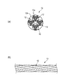
図4は、環状金属コードC1を製造するために用意されたコア用原コードを示す図であり、(a)は径方向の断面図であり、(b)は側面図である。
図4に示すように、金属コード(コア用原コード)13は、S撚した3本の金属素線12aからなるストランド材12bを3本S撚にて撚り合わせてなる4本のコア用ストランド材12を、撚り合せた(上撚りした)撚線構造を有している。上撚り方向はZ撚である。
Then, the manufacturing method of the cyclic | annular metal cord C1 is demonstrated.
4A and 4B are views showing a core core cord prepared for manufacturing the annular metal cord C1, where FIG. 4A is a sectional view in the radial direction and FIG. 4B is a side view.
As shown in FIG. 4, the metal cord (core core cord) 13 is composed of four core strands obtained by twisting three
金属コード13のコア用ストランド材12は、環状金属コードC1の環状コア11を構成するために用いられる。これら4本のコア用ストランド材12は、撚り合わせて金属コード13とする際、コア用ストランド材12を構成する金属素線12aの直径に応じた直径型付け率にてそれぞれ螺旋状の型付けを施しておく。
The
このような金属コード13を解撚して、各コア用ストランド材12に分け、これらコア用ストランド材12の1本を用いて1つの環状コア11を製造する。用いるコア用ストランド材12の一部に樹脂繊維が含まれていてもよい。
金属コード13から取り出した1本のコア用ストランド材12は、図5に示すように、他のコア用ストランド材12が存在していた箇所に螺旋状の空隙部5aが形成されている。この空隙部5aは、金属コード13の他の3本のコア用ストランド材12の断面積の合計の断面積を有している。
Such a
As shown in FIG. 5, one
1本のコア用ストランド材12を、図6(a)に示すように1周(または2周)環状にして、環状にした部分の螺旋状の空隙部5aに両端の余長部12cを巻き付けて嵌め入れ、環状コア11とする。余長部12cを嵌め入れていない箇所(矢視bの箇所)の断面図が図6(b)であり、余長部12cを嵌め入れた箇所(矢視cの箇所)の断面図が図6(c)である。図6(b)に示すように、環状コア11における余長部12cを嵌め入れていない箇所では、断面でみてコア用ストランド材12は1本だけであり、金属コード13のときに撚り合わされていた他の3本のコア用ストランド材12の箇所は空隙部5aとなっている。また、図6(c)に示すように、環状コア11における余長部12cを嵌め入れた箇所では、断面でみてコア用ストランド材12は2本あり、空隙部5aの一部に余長部12cが配置されている。このように形成された環状コア11は、1本のコア用ストランド材12同士が螺旋状に巻き付けられて環状とされているので、環状径等の形状が安定する。
As shown in FIG. 6 (a), one
図7は、環状金属コードC1を製造するために用意された側線用原コードを示す図であり、(a)は径方向の断面図であり、(b)は側面図である。
図7に示すように、金属コード(側線用原コード)14は、S撚した7本の金属素線10からなるストランド材10aを7本S撚にて撚り合わせてなる8本の側線用ストランド材1を、仮コアストランド材(仮コア材)15の周囲に撚り合せた(上撚りした)撚線構造を有している。上撚り方向はZ撚である。仮コアストランド材15は、側線用ストランド材1よりも直径が大きいものであり、例えば、7本の金属素線を撚り合わせてなるストランド材を7本撚り合わせた構造を有する。
FIGS. 7A and 7B are diagrams showing a side wire original cord prepared for manufacturing the annular metal cord C1, where FIG. 7A is a sectional view in the radial direction, and FIG. 7B is a side view.
As shown in FIG. 7, the metal cord (side wire original cord) 14 is composed of eight strands for side wires formed by twisting seven
金属コード14の側線用ストランド材1は、環状金属コードC1を構成するために用いられる。これら8本の側線用ストランド材1は、撚り合わせて金属コード14とする際、側線用ストランド材1を構成する金属素線10の直径に応じた直径型付け率にてそれぞれ螺旋状の型付けを施しておく。
The
金属素線10の直径が0.03mm以上0.14mm以下である場合、可能な限り線径を細くして、ストランド材をしなやかなものとすることができる。その場合には側線用ストランド材1の剛性が低くなるので、側線用ストランド材1の直径型付け率を大きくすることができるが、その反面、撚り合わせの際などに張力がかかると型付けが元に戻りやすい。型付けは、例えば千鳥配列された円筒ピンの間を通過させることにより行うので、型付けが戻りやすいことを見越して無理に直径型付け率を大きくすると、円筒ピンと側線用ストランド材1との摩擦力が大きくなり、型付けされた状態の側線用ストランド材1の真直性が維持できなくなる。そのような側線用ストランド材1を用いて環状金属コードC1を作製しても側線用ストランド材1同士の撚り合わせが安定せず、好ましくない。金属素線10の直径が0.14mm以下である場合には、金属コード14を作製する際に、側線用ストランド材1の螺旋波付け高さの絶対値を大きくするため、図7に示すようにコアストランドの直径D2をストランド材1の直径D3より増径し、その分、側線用ストランド材1の本数を環状金属コード化した時より少なくとも1本増やして(図7では2本増やしている)、側線用ストランド材1の直径型付け率を91%以下とすることで、真直性を維持しやすくし、型付けが戻りにくくしている。また、直径型付け率を70%以上とすることで、側線用ストランド材1の内1本を環状コア11の周囲で自身の螺旋状の空隙部に複数周回数嵌め入れる際に、嵌め入れにくくならない程度の螺旋形状を確保している。
When the diameter of the
このようなことから、金属素線10の直径が0.03mm以上0.14mm以下である場合では、金属コード14の作製においては、使用する仮コア材を増径し、側線用ストランド材1の本数を増やした上で、付与する側線用ストランド材1の直径型付け率を80%前後に設定することが好ましい。これにより、図7の金属コード14を解撚して側線用ストランド材1を取り出すと、側線用ストランド材1の螺旋波付け高さ(自己径含む)が、環状金属コードC1の断面直径を越える程度になる。
Therefore, in the case where the diameter of the
金属素線10の直径が0.15mm以上である場合、側線用ストランド材1の剛性を良好に維持することができ、環状金属コードC1を変形に耐え得るものとすることができる。また、金属素線10の直径が0.30mm以下であるので、側線用ストランド材1の剛性が過度に大きくならずにすむ。したがって、環状金属コードC1は、繰り返し曲げ応力による疲労破断を生じにくくすることができる。
When the diameter of the
金属素線10の直径が0.15mm以上0.30mm以下である場合、金属コード14の作製においては、比較的型付けを施しやすいため、側線用ストランド材1の直径型付け率を100%超にし易い。
When the diameter of the
なお、金属コード14における側線用ストランド材1の本数は、環状金属コードC1の用途に応じて金属素線径を含めた側線用ストランド材1の撚り構造と環状金属コードC1に必要な側線用ストランド材1の本数を決定し、環状金属コードC1に供される側線用ストランド材1の直径型付け率から決められる。金属素線径が比較的細く、直径型付け率を大きくできない場合には、使用する仮コア材を増径するのに加え、金属コード14の側線用ストランド材1の本数を、環状金属コードC1に必要な側線用ストランド材1の周回数より多くする。金属素線径が比較的太く、直径型付け率を大きくできる場合には、金属コード14の側線ストランド材1の本数を、環状金属コードC1に必要な側線用ストランド材1の周回数と同数か、または周回数より少なくする。環状金属コードC1とした状態での側線用ストランド材1の直径型付け率が、101%以上となるように調整することが好ましい。
In addition, the number of the side
このような金属コード14を解撚して、各側線用ストランド材1に分け、これら側線用ストランド材1の1本を用いて1つの環状金属コードC1を製造する。
なお、金属コード14の仮コア材は環状金属コードC1を構成するものではない。そのため、仮コア材として、仮コアストランド材15の代わりに同じ径の軟鋼材のモノフィラメントを1本用いてもよい。
Such a
The temporary core material of the
そして、上記のように金属コード14から取り出した1本の側線用ストランド材1は、図5に示したコア用ストランド材12と同様に、他の側線用ストランド材1が存在していた箇所に螺旋状の空隙部5が形成されている。この空隙部5は、金属コード14の中心の中空部(仮コア材の部分)及び他の7本の側線用ストランド材1の断面積の合計の断面積を有している。
And the one
次いで、図8に示すように、環状コア11の周囲に側線用ストランド材1を複数周回(6周)環状に巻き付けていく。まず側線用ストランド材1の長さの略1/6分の長さを環状にしつつ環状コア11の周囲に巻き付けて、その環状部分1dにおける側線用ストランド材1の螺旋状の空隙部5に側線用ストランド材1の余長部1eを嵌め入れて、さらに複数周回(5周)環状に巻き付けていく。なお、側線用ストランド材1の巻き付けの始端部1fは、予め螺旋状にくせ付けされた波の高さが小さくなるように直線化して伸ばしておくとよい。側線用ストランド材1における空隙部5は、金属素線10の直径型付け率により異なるが、5周環状に巻き付けられる側線用ストランド材1の余長部1eが環状コア11の周囲で側線用ストランド材1自身の空隙部5に嵌め入れられる。巻き付けられた側線用ストランド材1の隣り合う余長部1e同士が径方向に密着された状態となるか、若干の隙間を有して配置される。
Next, as shown in FIG. 8, the side
また、側線用ストランド材1を環状コア11の周囲に所定の複数周回数巻き付けた後、図9に示すように、側線用ストランド材1の余長部1e及び始端部1fを、環状に巻き付けられた側線用ストランド材1同士の内側の空間(環状コア11の空隙部)に嵌め入れる。その際、両余長部(余長部1eと始端部1f)が交差した箇所でどちらか一方を他方に2周回巻き付けてから、余長部1eと始端部1f同士を引っ張る。このようにすると、巻き付けた箇所を直線化させる力が作用し、巻き付けた箇所が環状コア11の空隙部に落とし込まれる。また、始端部1fを直線化して伸ばしておくとよい。これにより、側線用ストランド材1同士、及び側線用ストランド材1と環状コア11との接触抵抗が大きくなって強力に保持され、余長部1e及び始端部1fの抜けが防止される。
Further, after the side
また、余長部1e及び始端部1fの巻き付け回数は、1回でも構わないが、2回以上であると周回されている側線用ストランド材1の間から巻き付け箇所が急角度で内側の空間(環状コア11の空隙部)に入り込み、周囲に螺旋状に巻かれた側線用ストランド材1との接触抵抗が大きくなって強力に保持され、抜けが確実に防止される。
In addition, the number of windings of the
巻き付け箇所を環状コア11の空隙部に落とし込んだ後、側線用ストランド材1同士の間から外に出ている両端末の余長(余長部1e及び始端部1f)を、その側線用ストランド材1同士の隙間に沿って巻き付けつつ環状に沿って移動させながら、環状コア11の空隙部に押し込んでいく。このとき、余長部1e及び始端部1fは、引き伸ばして略直線化されているので、隙間への挿し込みを容易に行うことができる。そして、このように側線用ストランド材1同士の隙間へ余長部1e及び始端部1fを挿し込むと、余長部1e及び始端部1fが6本の側線用ストランド材1の内側に形成されている環状コア11の空隙部に挿し入れられる。なお、余長部1e及び始端部1fを環状コア11の空隙部に落とし込んだ箇所の断面は、図3に示しており、それ以外の箇所の断面は、図2(a)に示している。
After dropping the winding portion into the gap of the
また、巻き付け箇所が側線用ストランド材1同士の間から内側の空間に入り込むので、側線用ストランド材1の始端部1f及び余長部1eを巻き付けた箇所が環状金属コードC1の外周に凸状に残ることがない。両端末の巻き付け箇所が凸状に残っていると、繰り返し曲げのかかる使用状態ではそこに負荷が集中して耐久性が低下するなどの不具合が生じるおそれがあるが、この環状金属コードC1では外周に凸部が存在しないので、そのような不具合は発生せず、環状方向に均一な特性を有し耐久性が良好である。
Moreover, since the winding location enters the inner space from between the side
このように、環状金属コードC1は、環状コア11の周囲に側線用ストランド材1が巻き付けられて構成されているため、その環状径は環状コア11によって決まる。そのため、環状金属コードC1を量産する際にも個々の環状金属コードC1の環状径のばらつきが発生することを抑制できる。また、金属コード13を解撚して得られた1本のコア用ストランド材12を用いて、他のコア用ストランド材12の抜けた螺旋状の空隙部5に嵌め入れて環状コア11を形成するので、コア用ストランド材12同士の接触抵抗によって環状コア11の形状が安定しやすく、環状金属コードC1の形状も安定する。
As described above, the annular metal cord C <b> 1 is formed by winding the side
また、環状コア11の周りには、側線用ストランド材1を環状に複数周巻き付け、他の側線用ストランド材1の抜けた螺旋状の空隙部5に螺旋状に巻き付けるので、側線用ストランド材1同士の接触抵抗によって環状金属コードの形状も安定する。隣り合う側線用ストランド材1同士の接触抵抗が得られ、側線用ストランド材1の全長に亘って側線用ストランド材1同士が拘束されるため、繰り返し負荷が加わっても撚り緩みが生じにくい。また、側線用ストランド材1同士の接触抵抗によって巻き付け状態が維持されるため、端末処理を簡素なものにすることができる。このように本実施形態によれば、継続的な繰り返し負荷に対しても側線用ストランド材1の撚り緩みが生じず、側線用ストランド材1を巻き付けた形状を維持することができる環状金属コードC1を容易に製造することができる。
Further, the side
また、側線用ストランド材1が単線ではなく、複数の金属素線10同士を撚り合わせた線材であるため、側線用ストランド材1表面の凹凸により側線用ストランド材1同士の接触抵抗も大きくなるので、撚り緩みがさらに生じにくくなる。また、環状金属コードC1の柔軟性が向上し、外力に対して均一負荷となりやすいので破断強度の低下を抑制できる。
Moreover, since the side
また、側線用ストランド材1は、金属コード14の状態でZ撚方向の螺旋状の型付けが施されている。そのため側線用ストランド材1同士は、Z撚、つまり側線用ストランド材1を構成する金属素線10の撚り方向(S/S撚構造)とは逆方向に巻き付けられる。すなわち、環状金属コードC1はS/S撚構造とZ巻構造を組み合わせたものとなる。金属素線10の撚り方向と、側線用ストランド材1の巻き付け方向とが逆であるため、環状金属コードC1の機械的特性に方向性が生じることが抑制されて捩れにくく、表面外観に凹凸の少ない環状金属コードC1を得ることができる。また、環状金属コードC1を環状方向に沿って回転させて使用する場合でも蛇行しにくくなる。
Further, the side
また、上記実施形態では、金属コード14を構成する8本の側線用ストランド材1の内の1本を用いて環状金属コードC1を製造したが、残りの7本のそれぞれの側線用ストランド材1についても同様に、前述したように、環状コア11の周りに環状に複数周巻き付けて環状金属コードC1を製造するとよい。これにより、経済性を高めることができる。また、環状コア11の製造についても同様に、金属コード13を構成する4本のコア用ストランド材12のうち、残りの3本をそれぞれ用いて環状コア11をそれぞれ製造するとよい。
Moreover, in the said embodiment, although the cyclic | annular metal cord C1 was manufactured using one of the eight side
なお、上記実施形態では、環状金属コードC1の断面における側線用ストランド材1の本数が6本の場合を例示して説明したが、断面における側線用ストランド材1は、6本に限定されない。側線用ストランド材1の構成も、適宜変更可能である。
In addition, although the said embodiment illustrated and demonstrated the case where the number of the
次に、上述した構成を有する環状金属コードC1を備える無端金属ベルトの一例について説明する。図10は本実施形態に係る無端金属ベルトの使用状態を示す模式的な斜視図である。 Next, an example of an endless metal belt provided with the annular metal cord C1 having the above-described configuration will be described. FIG. 10 is a schematic perspective view showing a use state of the endless metal belt according to the present embodiment.
無端金属ベルトB1は、例えば図10に示されるような、精密機器やその他の産業機械で使用されている減速機30用に用いられる。無端金属ベルトB1は、並行して配列された3本の環状金属コードC1からなり、小径の駆動側プーリ32と大径の被駆動側プーリ34との間の動力伝達を担っている。駆動側プーリ32の回転中心には、駆動用モータ36の駆動軸が接続されている。駆動側プーリ32及び被駆動側プーリ34の外周には各環状金属コードC1を安定的に掛け渡すための円周溝が形成され、無端金属ベルトB1を駆動側プーリ32及び被駆動側プーリ34に掛け渡すことにより、駆動側プーリ32の回転力が無端金属ベルトB1を介して被駆動側プーリ34に伝達される。その際、駆動側プーリ32の回転速度は被駆動側プーリ34にて減速され、駆動側プーリ32のトルクは被駆動側プーリ34にて増大される。被駆動側プーリ34は、例えば図示せぬ他のプーリ等に軸接続され、動力を伝達する。
The endless metal belt B1 is used for a
環状金属コードC1は、先に述べたように破断強度が非常に大きい。また、1本の側線用ストランド材1が、環状コア11の周りに環状に複数周巻き付けられるとともに、他の側線用ストランド材1の抜けた螺旋状の空隙部5に螺旋状に巻き付けられているので、外周に凸部が存在せず、プーリ32,34に巻回することにより、環状金属コードC1自体の自転がなくされる。つまり、自転が生じないので、疲労を抑制することができ、また、環状コア11によって環状金属コードC1毎の環状径のばらつきが小さく抑えられているので、荷重のばらつきが少なく抑えられ、安定したベルトの走行性が得られ、長寿命化も図ることができる。なお、焼鈍処理を施した場合では、側線用ストランド材1の撚り合わせ時の加工歪を除去することができ、さらに耐久性を高めることができる。
The annular metal cord C1 has a very high breaking strength as described above. Further, a
また、本実施形態の無端金属ベルトB1において、駆動側プーリ32及び被駆動側プーリ34に環状金属コードC1がそれぞれ3本ずつ掛け渡される形態としたが、掛け渡される環状金属コードC1の本数はこれに限られない。求められる駆動力またはベルト張力に応じて、環状金属コードC1の本数を調整することが可能である。
In the endless metal belt B1 of the present embodiment, three annular metal cords C1 are stretched over the driving
また、本実施形態は、環状金属コードを、減速機において動力を伝達する無端金属ベルトに適用したものであるが、本発明の環状金属コードは、減速機以外で使用される無端金属ベルトにも適用することができる。例えば、プリンタをはじめとする印刷機において紙送りローラ間の動力伝達を担う無端金属ベルト、一軸ロボットの直行駆動を担う無端金属ベルト、X−Yテーブル機構の駆動や三次元のキャリッジ駆動を担う無端金属ベルト、光学機器や検査機、あるいは測定器内において精密駆動を担う無端金属ベルト、自動車の無段変速機における駆動側プーリ及び被駆動側プーリの間の動力伝達を担う無端金属ベルト等に適用可能である。 In the present embodiment, the annular metal cord is applied to an endless metal belt that transmits power in a reduction gear. However, the annular metal cord of the present invention is also applicable to an endless metal belt that is used other than the reduction gear. Can be applied. For example, an endless metal belt responsible for power transmission between paper feed rollers in a printer such as a printer, an endless metal belt responsible for direct drive of a single-axis robot, an endless metal belt responsible for driving an XY table mechanism or driving a three-dimensional carriage Applicable to metal belts, endless metal belts responsible for precision driving in optical instruments and inspection machines, measuring instruments, endless metal belts responsible for power transmission between driving pulleys and driven pulleys in continuously variable transmissions for automobiles, etc. Is possible.
次に、本発明に係る環状金属コードの実施例について説明する。
上記実施形態のように製造した本発明に係る環状金属コードを実施例とし、環状コアのない環状金属コードを比較例として、耐久試験に供した。また、それぞれの環状径のばらつきも測定した。
Next, examples of the annular metal cord according to the present invention will be described.
An annular metal cord according to the present invention manufactured as in the above embodiment was used as an example, and an annular metal cord without an annular core was used as a comparative example for a durability test. Moreover, the dispersion | variation in each annular diameter was also measured.
(1)3×3×0.09+6×7×7×0.08の環状金属コードの作製
(コア用原コードの作製)
スチールコード用途の直径3.8mmの線材を酸洗皮膜処理した後、乾式伸線機により直径1.8mmまで伸線加工し、加熱、パテンチング、酸洗皮膜処理を行った後、再度乾式伸線機により直径0.55mmまで伸線加工する。これを再加熱、パテンチング、酸洗、水洗した後、直径0.09mmまで伸線加工した金属素線を3リールに巻き取り、再度サプライしてバンチャー型撚線機を用いて7.5mmの撚りピッチでS撚りにて撚り合わせる。この3×0.09の線材を3リールに所定量巻き取り、再度サプライしてバンチャー型撚線機を用いて6.5mmの撚りピッチでS撚りにて撚り合わせる。なお、バンチ撚りの場合、プレフォーム装置を使用しなくても93%前後の直径型付け率になるように調整できる。このストランド材を所定量巻き取ったリールを4リール用意する。4リールのストランド材を4本撚りができるバンチャー型撚線機を用いて15.0mmの撚りピッチでZ撚りにて所定量上撚りして、4×3×3×0.09のコア用原コードとする。
(1) Production of 3 × 3 × 0.09 + 6 × 7 × 7 × 0.08 annular metal cord (production of core cord)
After a 3.8 mm diameter wire rod for steel cord application is pickled, it is drawn to a diameter of 1.8 mm with a dry wire drawing machine, heated, patented, and pickled, then dry drawn again. The wire is drawn to a diameter of 0.55 mm using a machine. After reheating, patenting, pickling and rinsing, the metal wire drawn to a diameter of 0.09 mm is wound on 3 reels, supplied again, and twisted 7.5 mm using a buncher type twisting machine. Twist with S twist at the pitch. A predetermined amount of this 3 × 0.09 wire is wound up on three reels, supplied again, and twisted with an S twist at a 6.5 mm twist pitch using a buncher type twist wire machine. In the case of bunch twisting, the diameter can be adjusted to about 93% without using a preform device. Four reels are prepared by winding a predetermined amount of this strand material. A 4 × 3 × 3 × 0.09 core raw material is obtained by twisting a predetermined amount by Z-twisting at a 15.0 mm twist pitch using a buncher-type twisted wire machine that can twist four 4-reel strands. Code.
(環状コアの作製)
コア用原コードを解撚して得られる4本のコア用ストランド材のうち、1本を使用して、例えば、直径200mmの環状径を形成し、その後、環状にした部分の螺旋状の空隙部5aに両端の余長部12cを巻き付けて嵌め入れ、環状コア11とする。
(Production of annular core)
One of the four core strand materials obtained by untwisting the core core cord is used to form, for example, an annular diameter of 200 mm in diameter, and then the spiral gap in the annular portion The
(側線用ストランド材の作製)
コア用ストランド材の作製と同様に、スチールコード用途の線材から直径0.55mmまで伸線加工した線を、再加熱、パテンチング、酸洗、水洗した後、ブラスめっき(銅めっき、亜鉛めっき後、加熱拡散により合金化)して直径0.55mmのブラスめっき鋼線とする。これを湿式伸線機により直径0.08mmまで伸線加工して金属素線(側線用ストランド材用)とし、これを所定量巻き取ったリールを7リール用意する。この直径0.08mmの金属素線を、7本撚り(1+6の構成)ができるチューブラー型撚線機を用いて3.0mmの撚りピッチでS撚りにて下撚り(子撚り)する。このとき、プレフォーム装置により事前に87%前後の直径型付け率になるように調整する。このストランド材を所定量巻き取ったリールを7リール用意する。子撚りした7本撚りのストランド材を用いて、7本撚り(1+6の構成)ができるチューブラー型撚線機を用いて9.0mmの撚りピッチでS撚りにて中撚り(親撚り)し、側線用ストランド材とする。このとき、プレフォーム装置により事前に87%前後の直径型付け率になるように調整する。このストランド材を所定量巻き取ったリールを8リール用意する。
(Production of strand material for side wires)
Similar to the production of the core strand material, the wire drawn to a diameter of 0.55 mm from the wire material used for the steel cord is reheated, patented, pickled, washed with water, and then subjected to brass plating (copper plating, galvanization, Alloyed by heat diffusion) to obtain a brass-plated steel wire having a diameter of 0.55 mm. This is drawn to a diameter of 0.08 mm by a wet wire drawing machine to form a metal strand (for side wire strand material), and 7 reels are prepared by winding a predetermined amount of this. This metal element wire having a diameter of 0.08 mm is subjected to under-twisting (child-twisting) with S-twisting at a 3.0-mm twisting pitch using a tubular twisting machine capable of seven strands (1 + 6 configuration). At this time, the preform apparatus is adjusted in advance so that the diameter molding rate is about 87%. Seven reels having a predetermined amount of the strand material wound thereon are prepared. Using a twisted strand material that has been twisted 7 strands, using a tubular twisted wire machine that can twist 7 strands (1 + 6 configuration), twist it in an S twist with a twist pitch of 9.0 mm (parent twist). A strand material for side wires is used. At this time, the preform apparatus is adjusted in advance so that the diameter molding rate is about 87%. Eight reels prepared by winding a predetermined amount of the strand material are prepared.
(側線用原コードの仮コア材の作製)
上記の直径0.55mmまで伸線加工した線を、湿式伸線機により直径0.145mmまで伸線加工して金属素線とし、これを所定量巻き取ったリールを7リール用意する。この直径0.145mmの金属素線を、7本撚り(1+6の構成)ができるチューブラー型撚線機を用いて4.5mmの撚りピッチでS撚りにて下撚り(子撚り)する。このとき、プレフォーム装置により事前に87%前後の直径型付け率になるように調整する。このストランド材を所定量巻き取ったリールを7リール用意する。子撚りした7本撚りのストランド材を用いて、7本撚り(1+6の構成)ができるチューブラー型撚線機を用いて14mmの撚りピッチでS撚りにて中撚り(親撚り)し、仮コア材とする。このとき、プレフォーム装置により事前に87%前後の直径型付け率になるように調整する。
(Preparation of temporary core material for side cords)
The wire drawn to a diameter of 0.55 mm is drawn to a diameter of 0.145 mm by a wet wire drawing machine to form a metal strand, and 7 reels are prepared by winding a predetermined amount. This metal element wire having a diameter of 0.145 mm is subjected to under-twisting (child-twisting) with S-twisting at a twisting pitch of 4.5 mm using a tubular twisted wire machine capable of seven strands (1 + 6 configuration). At this time, the preform apparatus is adjusted in advance so that the diameter molding rate is about 87%. Seven reels having a predetermined amount of the strand material wound thereon are prepared. Using a twisted strand material that has been twisted 7 strands, using a tubular twisted wire machine that can perform 7 strands (1 + 6 configuration), the strands are twisted in the S twist at a 14 mm twist pitch (parent twist). Use core material. At this time, the preform apparatus is adjusted in advance so that the diameter molding rate is about 87%.
(側線用原コードの作製)
上記の仮コア材(親撚り)1リールと側線用ストランド材(親撚り)8リールを用いて9本撚り(1+8の構成)ができるチューブラー型撚線機を用いて22.0mmの撚りピッチでZ撚りにて所定量上撚りして、1×7×7×0.145+8×7×7×0.08の側線用原コードとする。なお、プレフォーム装置を用いて事前に89%前後の直径型付け率に調整する。
(Preparation of original cords for side wires)
Twist pitch of 22.0 mm using a tubular twisted wire machine capable of nine strands (1 + 8 configuration) using one reel of the above temporary core material (parent twist) and eight reels of side wire strand material (parent twist). Then, a predetermined amount is twisted by Z twisting to obtain a side wire original cord of 1 × 7 × 7 × 0.145 + 8 × 7 × 7 × 0.08. In addition, it adjusts to the diameter shaping | molding rate of about 89% in advance using a preform apparatus.
(環状金属コードの作製)
上撚りした側線用原コードを、余長分αも含めて必要な環状金属コードの環状径(層心径:Di)の約26倍((Di)π×6+α)の長さで切断した後、全長にわたって解撚し、各側線用ストランド材に分離する。そして、上記環状コア(3×3×0.09)の周りに、上記解撚された側線用ストランド材(7×7×0.08)を6周回移動させながら側線用ストランド材自身の他の側線用ストランド材が抜けた空隙部を埋めるように環状金属コード化する。
(Production of ring metal cord)
After cutting the twisted side wire original cord with a length of about 26 times ((Di) π × 6 + α) of the necessary annular metal cord diameter (layer core diameter: Di) including the extra length α , Untwisting over the entire length and separating into strand materials for each side wire. And while moving the untwisted side wire strand material (7 × 7 × 0.08) around the annular core (3 × 3 × 0.09) 6 times, other side wire strand materials themselves An annular metal cord is formed so as to fill the void from which the side wire strand material is removed.
(端末処理)
環状コアの周囲に巻き付けた側線用ストランド材の巻き付け始端部と巻き付けの終端余長部を必要な長さだけ残して再切断し、始端部及び余長終端部のオーバーラップする螺旋形状を出来るだけ真直化して、端部同士が交差した箇所でどちらか一方を他方に2回巻き付けて引っ張り、巻き付け箇所を側線用ストランド材同士の間から環状コアのある側線用ストランド材同士の内側の空間に入れ込み、収容する。
(Terminal processing)
Re-cut leaving the necessary length of the winding start end of the side wire strand material wound around the annular core and the terminal end surplus length of the winding, so that the spiral shape overlaps the start end and surplus end as much as possible Straighten and pull one of the two ends around the other at the point where the ends intersect each other, pull the winding part into the space between the side line strand materials with the annular core from between the side line strand materials Contain.
このようにして作製した1×3×3×0.09+6×7×7×0.08の環状金属コードを、実施例とする。また、環状コアを無くして6×7×7×0.08の環状金属コードを作製したものを、比較例とする。 A 1 × 3 × 3 × 0.09 + 6 × 7 × 7 × 0.08 annular metal cord produced in this way is taken as an example. Moreover, what produced the 6x7x7x0.08 cyclic | annular metal cord without the cyclic | annular core is made into a comparative example.
(2)耐久試験
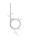
(2−1)耐久試験装置
図11に耐久試験装置を示す。図11に示すように、耐久性試験装置は、駆動モータ51によって回転される駆動プーリ52と、この駆動プーリ52に対して水平方向へ接離可能に支持された従動プーリ53と、従動プーリ53を駆動プーリ52から離間させる方向へ荷重を付与する張力付加部54とを備える。上記実施例、比較例の環状金属コードを試験する際の駆動プーリ52及び従動プーリ53の直径は、23.9mm(架けた環状金属コードの中心で直径25.0mm)とした。
(2) Durability Test (2-1) Durability Test Device FIG. 11 shows a durability test device. As shown in FIG. 11, the durability test apparatus includes a
張力付加部54は、従動プーリ53にロープ55を介して取り付けられた錘56と、ロープ55が掛けられた滑車57とを有し、錘56の荷重によって従動プーリ53が駆動プーリ52から離間される。そして、この張力付加部54では、錘56の重さを調整し、付加張力は、19.5kg(コードの強度の5%前後)とした。
The
(2−2)耐久試験方法
上記の耐久性試験装置の駆動プーリ52と従動プーリ53とに、各環状金属コードを巻き掛けて駆動プーリ52を3500rpmにて回転させ、環状金属コードに繰り返し引っ張り曲げ応力をかけ、環状金属コードの切断、弛み、ワイヤー(素線)の切れ等の不具合の発生の有無及び不具合発生までの耐久回数(換算回数)を調べて評価した。
(2-2) Durability Test Method Each annular metal cord is wound around the
(2−3)耐久試験結果
上記実施例、比較例の環状金属コードにおける耐久試験結果を、次表に示す。
(2-3) Durability Test Results Durability test results on the annular metal cords of the above examples and comparative examples are shown in the following table.
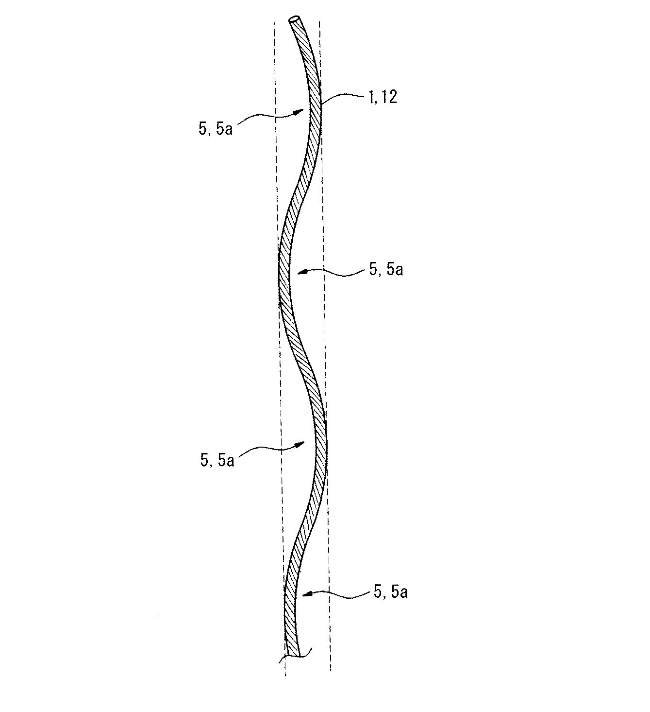
表1に示すように、実施例、比較例ともに、耐え得る繰り返し引っ張り曲げ回数が極めて多くなり、側線用ストランド材の始端部及び終端部の飛び出しもなかった。 As shown in Table 1, in both the examples and the comparative examples, the number of times of repeated bending that can be endured was extremely large, and the start and end portions of the side wire strand material did not protrude.
(3)コード環状径の寸法安定性
実施例、比較例の環状金属コードについて、環状径をそれぞれ目標直径200mmとして20サンプルずつ作製し、円錐台に嵌めてコード環状径を測定し、平均値及び標準偏差を調べた。測定結果を表2に示す。
(3) Dimensional stability of cord annular diameter For the annular metal cords of Examples and Comparative Examples, 20 samples each having an annular diameter of 200 mm were prepared, and fitted to a truncated cone to measure the cord annular diameter. The standard deviation was examined. The measurement results are shown in Table 2.
表2に示すように、平均コード環状径は比較例に対して実施例の方が目標直径200mmに近い値となり、コード環状径標準偏差は比較例に対して実施例の方が小さくなった。すなわち、環状コアを有する実施例の方が、所望の環状径が得られやすく、その環状径のばらつきも小さいことが確認できた。 As shown in Table 2, the average cord annular diameter in the example was closer to the target diameter of 200 mm than the comparative example, and the cord annular diameter standard deviation was smaller in the example than in the comparative example. In other words, it was confirmed that the example having the annular core can easily obtain a desired annular diameter, and the variation in the annular diameter is smaller.
1:側線用ストランド材、5,5a:空隙部、11:環状コア、12:コア用ストランド材、13:コア用原コード、14:側線用原コード、B1:無端金属ベルト、C1:環状金属コード 1: Strand material for side wire, 5, 5a: Cavity, 11: Ring core, 12: Strand material for core, 13: Original cord for core, 14: Original cord for side wire, B1: Endless metal belt, C1: Ring metal code
Claims (7)
少なくとも6本の側線用ストランド材が撚り合わされた側線用原コードを解撚した側線用ストランド材が、前記環状コアの周りに環状に複数周巻き付けられるとともに、他の側線用ストランド材の抜けた螺旋状の空隙部に螺旋状に巻き付けられていることを特徴とする環状金属コード。 A core core cord in which a plurality of core strand materials are twisted together is untwisted, and one core strand material is fitted into a spiral void portion from which another core strand material is removed while being annularly formed. Is formed as an annular core,
A side wire strand material obtained by untwisting a side wire original cord in which at least six side wire strand materials are twisted together is wound around the annular core in a plurality of circles, and a spiral from which other side wire strand materials are removed. An annular metal cord, wherein the annular metal cord is spirally wound around a gap.
前記環状コアのコア用ストランド材の両端余長部が、他のコア用ストランド材の抜けた螺旋状の空隙部に嵌め入れられて巻き付けられていることを特徴とする環状金属コード。 The annular metal cord according to claim 1,
An annular metal cord, wherein both ends of the core strand material of the annular core are wound by being fitted into a spiral void portion from which another core strand material is removed.
前記環状コアのコア用ストランド材の一部が樹脂繊維であることを特徴とする環状金属コード。 The annular metal cord according to claim 1 or 2,
Part of the core strand material of the annular core is a resin fiber.
前記樹脂繊維がアラミド繊維であることを特徴とする環状金属コード。 The annular metal cord according to claim 3,
An annular metal cord, wherein the resin fiber is an aramid fiber.
前記環状コアのコア用ストランド材と前記側線用ストランド材の撚り方向が同一方向であることを特徴とする環状金属コード。 The annular metal cord according to any one of claims 1 to 4,
The annular metal cord, wherein the strand material for the core of the annular core and the strand material for the side wire are twisted in the same direction.
少なくとも6本の側線用ストランド材が撚り合わされた側線用原コードを解撚した側線用ストランド材を、前記環状コアの周りに環状に複数周巻き付けるとともに、他の側線用ストランド材の抜けた螺旋状の空隙部に螺旋状に巻き付けることを特徴とする環状金属コードの製造方法。 Untwisting a core core cord in which a plurality of core strand materials are twisted together, and inserting one core strand material into a spiral void portion from which another core strand material is removed while being circular. Formed as an annular core,
A side wire strand material obtained by untwisting a side wire original cord in which at least six side wire strand materials are twisted together is wound around the annular core in a plurality of circles, and a spiral shape from which other side wire strand materials are removed. A method for producing an annular metal cord, characterized by being wound spirally around a gap portion of the ring.
Priority Applications (1)
| Application Number | Priority Date | Filing Date | Title |
|---|---|---|---|
| JP2010226797A JP2012082530A (en) | 2010-10-06 | 2010-10-06 | Annular metal cord, endless metal belt having the same and method for manufacturing the same |
Applications Claiming Priority (1)
| Application Number | Priority Date | Filing Date | Title |
|---|---|---|---|
| JP2010226797A JP2012082530A (en) | 2010-10-06 | 2010-10-06 | Annular metal cord, endless metal belt having the same and method for manufacturing the same |
Publications (1)
| Publication Number | Publication Date |
|---|---|
| JP2012082530A true JP2012082530A (en) | 2012-04-26 |
Family
ID=46241699
Family Applications (1)
| Application Number | Title | Priority Date | Filing Date |
|---|---|---|---|
| JP2010226797A Pending JP2012082530A (en) | 2010-10-06 | 2010-10-06 | Annular metal cord, endless metal belt having the same and method for manufacturing the same |
Country Status (1)
| Country | Link |
|---|---|
| JP (1) | JP2012082530A (en) |
Cited By (4)
| Publication number | Priority date | Publication date | Assignee | Title |
|---|---|---|---|---|
| JP2014234565A (en) * | 2013-05-31 | 2014-12-15 | 浪速製綱株式会社 | Wire rope |
| WO2016208262A1 (en) * | 2015-06-26 | 2016-12-29 | トクセン工業株式会社 | Operating rope |
| WO2017038154A1 (en) * | 2015-08-31 | 2017-03-09 | トクセン工業株式会社 | Hollow twisted wire for operation |
| CN112981993A (en) * | 2016-06-29 | 2021-06-18 | 东京制纲株式会社 | Synthetic fiber rope, and concrete structure and elongated object each comprising same |
-
2010
- 2010-10-06 JP JP2010226797A patent/JP2012082530A/en active Pending
Cited By (7)
| Publication number | Priority date | Publication date | Assignee | Title |
|---|---|---|---|---|
| JP2014234565A (en) * | 2013-05-31 | 2014-12-15 | 浪速製綱株式会社 | Wire rope |
| WO2016208262A1 (en) * | 2015-06-26 | 2016-12-29 | トクセン工業株式会社 | Operating rope |
| US10683609B2 (en) | 2015-06-26 | 2020-06-16 | Tokusen Kogyo Co., Ltd. | Manipulation rope |
| WO2017038154A1 (en) * | 2015-08-31 | 2017-03-09 | トクセン工業株式会社 | Hollow twisted wire for operation |
| US10426505B2 (en) | 2015-08-31 | 2019-10-01 | Tokusen Kogyo Co., Ltd. | Hollow stranded wire line for manipulation |
| CN112981993A (en) * | 2016-06-29 | 2021-06-18 | 东京制纲株式会社 | Synthetic fiber rope, and concrete structure and elongated object each comprising same |
| CN112981993B (en) * | 2016-06-29 | 2022-12-30 | 东京制纲株式会社 | Synthetic fiber rope, and concrete structure and elongated object each comprising same |
Similar Documents
| Publication | Publication Date | Title |
|---|---|---|
| US3090189A (en) | Elastic wire cables | |
| KR940007709B1 (en) | Steel cord for reinforcing rubber product | |
| JP3686451B2 (en) | Steel cord manufacturing method | |
| JP6548642B2 (en) | Straight monofilament for belt ply | |
| US4566261A (en) | Metallic cable and apparatus for manufacturing the same | |
| JP2012082530A (en) | Annular metal cord, endless metal belt having the same and method for manufacturing the same | |
| JP2011202321A (en) | Ring-form metal cord, endless metal belt and method for producing ring-form metal cord | |
| JP2011132620A (en) | Circular metal cord, endless metal belt and method for producing circular metal cord | |
| JPH05214685A (en) | Reverse strand binding device | |
| WO2010106875A1 (en) | Annular metal cord, endless metal belt and method of producing annular metal cord | |
| CN111535063A (en) | Steel cord, manufacturing method thereof and tire | |
| JP5219244B2 (en) | Steel cord | |
| JP2010249310A (en) | Transmission belt and method for manufacturing the same | |
| WO2010109735A1 (en) | Annular metallic cord, endless metallic belt, and process for producing annular metallic cord | |
| JP2010209504A (en) | Annular metal cord, endless metal belt, and method for producing annular metal cord | |
| JP2009275338A (en) | Annular metal cord, endless metal belt, and method for manufacturing annular metal cord | |
| JP5759846B2 (en) | Stranded ring and method for manufacturing the same | |
| JP2011117090A (en) | Cyclic metal cord, endless metal belt and method for producing cyclic metal cord | |
| JP2009281583A (en) | Transmission belt and its method for manufacturing | |
| EP0040877A1 (en) | Metal wire cord having strands with parallel filaments | |
| CN113846498B (en) | Steel wire rope for elevator with composite rope core structure | |
| JP2001003281A (en) | Production of steel cord and twisting machine therefor | |
| JP3588402B2 (en) | Steel cord for reinforcing rubber articles, method for producing the same, and apparatus for producing the same | |
| JP2011202758A (en) | Driving belt and method of manufacturing the same | |
| JP2018178319A (en) | Steel cord for rubber article reinforcement, manufacturing method thereof, and buncher twisting wire machine |
Legal Events
| Date | Code | Title | Description |
|---|---|---|---|
| RD02 | Notification of acceptance of power of attorney |
Free format text: JAPANESE INTERMEDIATE CODE: A7422 Effective date: 20120502 |