EP3293239B1 - Élément adhésif et ensemble de soupape - Google Patents
Élément adhésif et ensemble de soupape Download PDFInfo
- Publication number
- EP3293239B1 EP3293239B1 EP17190062.4A EP17190062A EP3293239B1 EP 3293239 B1 EP3293239 B1 EP 3293239B1 EP 17190062 A EP17190062 A EP 17190062A EP 3293239 B1 EP3293239 B1 EP 3293239B1
- Authority
- EP
- European Patent Office
- Prior art keywords
- carrier layer
- adhesive
- layer
- adhesive material
- carrier
- Prior art date
- Legal status (The legal status is an assumption and is not a legal conclusion. Google has not performed a legal analysis and makes no representation as to the accuracy of the status listed.)
- Not-in-force
Links
Images


Classifications
-
- C—CHEMISTRY; METALLURGY
- C09—DYES; PAINTS; POLISHES; NATURAL RESINS; ADHESIVES; COMPOSITIONS NOT OTHERWISE PROVIDED FOR; APPLICATIONS OF MATERIALS NOT OTHERWISE PROVIDED FOR
- C09J—ADHESIVES; NON-MECHANICAL ASPECTS OF ADHESIVE PROCESSES IN GENERAL; ADHESIVE PROCESSES NOT PROVIDED FOR ELSEWHERE; USE OF MATERIALS AS ADHESIVES
- C09J5/00—Adhesive processes in general; Adhesive processes not provided for elsewhere, e.g. relating to primers
-
- B—PERFORMING OPERATIONS; TRANSPORTING
- B01—PHYSICAL OR CHEMICAL PROCESSES OR APPARATUS IN GENERAL
- B01L—CHEMICAL OR PHYSICAL LABORATORY APPARATUS FOR GENERAL USE
- B01L3/00—Containers or dishes for laboratory use, e.g. laboratory glassware; Droppers
- B01L3/50—Containers for the purpose of retaining a material to be analysed, e.g. test tubes
- B01L3/502—Containers for the purpose of retaining a material to be analysed, e.g. test tubes with fluid transport, e.g. in multi-compartment structures
- B01L3/5027—Containers for the purpose of retaining a material to be analysed, e.g. test tubes with fluid transport, e.g. in multi-compartment structures by integrated microfluidic structures, i.e. dimensions of channels and chambers are such that surface tension forces are important, e.g. lab-on-a-chip
- B01L3/502707—Containers for the purpose of retaining a material to be analysed, e.g. test tubes with fluid transport, e.g. in multi-compartment structures by integrated microfluidic structures, i.e. dimensions of channels and chambers are such that surface tension forces are important, e.g. lab-on-a-chip characterised by the manufacture of the container or its components
-
- B—PERFORMING OPERATIONS; TRANSPORTING
- B01—PHYSICAL OR CHEMICAL PROCESSES OR APPARATUS IN GENERAL
- B01L—CHEMICAL OR PHYSICAL LABORATORY APPARATUS FOR GENERAL USE
- B01L3/00—Containers or dishes for laboratory use, e.g. laboratory glassware; Droppers
- B01L3/50—Containers for the purpose of retaining a material to be analysed, e.g. test tubes
- B01L3/502—Containers for the purpose of retaining a material to be analysed, e.g. test tubes with fluid transport, e.g. in multi-compartment structures
- B01L3/5027—Containers for the purpose of retaining a material to be analysed, e.g. test tubes with fluid transport, e.g. in multi-compartment structures by integrated microfluidic structures, i.e. dimensions of channels and chambers are such that surface tension forces are important, e.g. lab-on-a-chip
- B01L3/502738—Containers for the purpose of retaining a material to be analysed, e.g. test tubes with fluid transport, e.g. in multi-compartment structures by integrated microfluidic structures, i.e. dimensions of channels and chambers are such that surface tension forces are important, e.g. lab-on-a-chip characterised by integrated valves
-
- C—CHEMISTRY; METALLURGY
- C09—DYES; PAINTS; POLISHES; NATURAL RESINS; ADHESIVES; COMPOSITIONS NOT OTHERWISE PROVIDED FOR; APPLICATIONS OF MATERIALS NOT OTHERWISE PROVIDED FOR
- C09J—ADHESIVES; NON-MECHANICAL ASPECTS OF ADHESIVE PROCESSES IN GENERAL; ADHESIVE PROCESSES NOT PROVIDED FOR ELSEWHERE; USE OF MATERIALS AS ADHESIVES
- C09J7/00—Adhesives in the form of films or foils
- C09J7/20—Adhesives in the form of films or foils characterised by their carriers
- C09J7/22—Plastics; Metallised plastics
- C09J7/26—Porous or cellular plastics
-
- C—CHEMISTRY; METALLURGY
- C09—DYES; PAINTS; POLISHES; NATURAL RESINS; ADHESIVES; COMPOSITIONS NOT OTHERWISE PROVIDED FOR; APPLICATIONS OF MATERIALS NOT OTHERWISE PROVIDED FOR
- C09J—ADHESIVES; NON-MECHANICAL ASPECTS OF ADHESIVE PROCESSES IN GENERAL; ADHESIVE PROCESSES NOT PROVIDED FOR ELSEWHERE; USE OF MATERIALS AS ADHESIVES
- C09J7/00—Adhesives in the form of films or foils
- C09J7/20—Adhesives in the form of films or foils characterised by their carriers
- C09J7/29—Laminated material
-
- F—MECHANICAL ENGINEERING; LIGHTING; HEATING; WEAPONS; BLASTING
- F16—ENGINEERING ELEMENTS AND UNITS; GENERAL MEASURES FOR PRODUCING AND MAINTAINING EFFECTIVE FUNCTIONING OF MACHINES OR INSTALLATIONS; THERMAL INSULATION IN GENERAL
- F16K—VALVES; TAPS; COCKS; ACTUATING-FLOATS; DEVICES FOR VENTING OR AERATING
- F16K99/00—Subject matter not provided for in other groups of this subclass
- F16K99/0001—Microvalves
- F16K99/0034—Operating means specially adapted for microvalves
- F16K99/0042—Electric operating means therefor
- F16K99/0044—Electric operating means therefor using thermo-electric means
-
- B—PERFORMING OPERATIONS; TRANSPORTING
- B01—PHYSICAL OR CHEMICAL PROCESSES OR APPARATUS IN GENERAL
- B01L—CHEMICAL OR PHYSICAL LABORATORY APPARATUS FOR GENERAL USE
- B01L2300/00—Additional constructional details
- B01L2300/08—Geometry, shape and general structure
- B01L2300/0887—Laminated structure
-
- B—PERFORMING OPERATIONS; TRANSPORTING
- B01—PHYSICAL OR CHEMICAL PROCESSES OR APPARATUS IN GENERAL
- B01L—CHEMICAL OR PHYSICAL LABORATORY APPARATUS FOR GENERAL USE
- B01L2400/00—Moving or stopping fluids
- B01L2400/06—Valves, specific forms thereof
- B01L2400/0677—Valves, specific forms thereof phase change valves; Meltable, freezing, dissolvable plugs; Destructible barriers
-
- C—CHEMISTRY; METALLURGY
- C09—DYES; PAINTS; POLISHES; NATURAL RESINS; ADHESIVES; COMPOSITIONS NOT OTHERWISE PROVIDED FOR; APPLICATIONS OF MATERIALS NOT OTHERWISE PROVIDED FOR
- C09J—ADHESIVES; NON-MECHANICAL ASPECTS OF ADHESIVE PROCESSES IN GENERAL; ADHESIVE PROCESSES NOT PROVIDED FOR ELSEWHERE; USE OF MATERIALS AS ADHESIVES
- C09J2301/00—Additional features of adhesives in the form of films or foils
- C09J2301/50—Additional features of adhesives in the form of films or foils characterized by process specific features
- C09J2301/502—Additional features of adhesives in the form of films or foils characterized by process specific features process for debonding adherents
-
- F—MECHANICAL ENGINEERING; LIGHTING; HEATING; WEAPONS; BLASTING
- F16—ENGINEERING ELEMENTS AND UNITS; GENERAL MEASURES FOR PRODUCING AND MAINTAINING EFFECTIVE FUNCTIONING OF MACHINES OR INSTALLATIONS; THERMAL INSULATION IN GENERAL
- F16K—VALVES; TAPS; COCKS; ACTUATING-FLOATS; DEVICES FOR VENTING OR AERATING
- F16K99/00—Subject matter not provided for in other groups of this subclass
- F16K2099/0073—Fabrication methods specifically adapted for microvalves
- F16K2099/008—Multi-layer fabrications
Definitions
- the invention is in the field of mechanics and joining technology and can be used with particular advantage in the field of microfluidics, but also in other fields.
- One of the most common joining techniques for connecting different components is gluing using an adhesive.
- a particular challenge here is to create releasable adhesive connections that can be released again without great effort, and in particular without damaging the connected components.
- a material component is often used that can be inactivated thermally or by radiation, in particular UV radiation.
- an adhesive can be liquefied by the action of temperature in order to break an adhesive connection.
- UV radiation can also make the adhesive brittle in order to break an adhesive bond.
- the swelling or expansion of certain constituents of the adhesive can also be achieved by heating and thereby indirectly loosening the adhesive connection.
- Openings can also be closed by gluing, so that the valve arrangement can be closed by gluing and opened again by loosening the glue.
- the WO 2005/111435 A2 deals with an arrangement for controlling fluid movements in a system of channels by means of microfluidics.
- the present invention is based on the object of creating an adhesive element which is easy to glue and the glueing of which can be solved easily and without problems.
- Claim 14 relates to a valve arrangement in which an adhesive element according to the invention is used.
- the invention relates to an adhesive element for gluing to at least one component surface, with at least one first carrier layer which carries a layer of a first adhesive material at least on a first outside in a first adhesive area and which is permeable to the first adhesive material, and with at least one absorption layer connected to the first carrier layer, the first adhesive material and the first carrier layer being coordinated with one another in such a way that the first adhesive material, when it is in liquid form, is at least partially sucked into the first carrier layer by capillary action, and the absorption layer is designed in this way that it is more heavily wetted by the liquid first adhesive material than the first carrier layer due to the capillary action.
- the first carrier layer can be glued to a component surface by means of the first adhesive material. At least in the first adhesive area, a surface of the first carrier layer is coated with the adhesive material, so that the first adhesive area is available for connection to the component surface. In this way, for example, an opening in the component surface, for example a channel, can be closed by gluing on the first carrier layer.
- the carrier layer can be formed by a solid and stiff material or also by a pliable layer.
- the liquefied first adhesive material wets the carrier layer, it can reach the absorption layer and be absorbed from there, the liquefied adhesive material being absorbed more strongly by the absorption layer than by the carrier layer in the contact area of the absorption layer with the first carrier layer, so that the Adhesive material is conveyed from the carrier layer into the absorption layer and thus away from the first adhesive area.
- the first adhesive material can be liquefied, for example, by increasing the temperature, but also by changing other physical parameters, for example by applying an electrical voltage or a magnetic field to change the viscosity, by the action of ultrasound or the action of UV radiation or another form of radiation.
- the adhesive element has, in addition to the first carrier layer, a second carrier layer which has a layer of a second adhesive material on an outside in a second adhesive area, the second carrier layer being permeable to the second adhesive material, such that the second adhesive material, if it is in liquid form, is at least partially sucked into the second carrier layer by capillary action, an absorption layer being connected to the second carrier layer, which is more wetted by the second adhesive material in liquefied form than the second carrier layer.
- the first and / or the second carrier layer can be designed to be porous or consist of a porous material, the pores being at least partially open. This can be achieved, for example, by using foamed, open-pored materials. Instead of bubble-like cavities, as in the case of a foamed material, channels (capillary channels) can also be provided in the material of one or more of the layers mentioned in order to achieve a capillary effect. These channels can be created during the production of the materials or also introduced or opened later.
- One or more of the layers can also be produced by sintering, for example.
- the material of which the carrier layer consists or the carrier layers and / or absorption layer (s) consist should in any case form a self-supporting framework, and preferably even if it absorbs liquefied adhesive, the layers should not change their volume / thickness.
- the individual layers, carrier layers as well as absorption layers can thus advantageously each have a sponge-like structure, form a self-supporting framework and also have a constant volume when absorbing adhesive.
- carrier layers and / or absorption layers can also consist of a nonwoven material and / or an absorbent fabric, for example a material consisting essentially of fiber sections or containing fiber sections, for example paper, or contain such a material.
- an adhesive element which has several adhesive areas, for example on different sides, for. B. can also be arranged on opposite sides of the adhesive element.
- an adhesive material is provided which can be liquefied and which can then be sucked into the respective carrier layer from the adhesive area. Since both carrier layers are connected with an absorption material, the adhesive material can be sucked further into the absorption layers so that the adhesive areas are largely free of the adhesive material after it has been released.
- the same adhesive material can be used for the two adhesive areas, but different adhesive materials can also be used for the different adhesive areas.
- the material of the carrier layers can also be different.
- a further embodiment of the invention provides that the second carrier layer is connected to the same absorption layer as the first carrier layer.
- the absorption layer can be connected to carrier layers on both sides and sandwiched between them. The absorption layer can then be in the center of the adhesive element and soak up the adhesive material in the liquid state through the carrier layers from different sides.
- a further embodiment of the invention can thus provide that the common absorption layer is arranged between the first carrier layer and the second carrier layer.
- the second carrier layer has the same composition as the first carrier layer, the second carrier layer in particular consisting of the same material as the first carrier layer.
- the nature of the second carrier layer is different from that of the first carrier layer, the second carrier layer in particular consisting of a different material than the first carrier layer.
- the adhesive element When using different carrier layers, the adhesive element can be designed in such a way that it has different adhesive properties in different adhesive areas and that the adhesive material thus has a different effect in the different adhesive areas. Even when the adhesive material liquefies, it can be sucked into the various carrier layers at different speeds and intensities.
- the second adhesive material is identical to the first adhesive material.
- the second adhesive material is different from the first adhesive material.
- the adhesive material can be removed simultaneously in the different adhesive areas, since it is subjected to the same physical conditions and is therefore liquefied at the different points of the adhesive element at approximately the same time. If different adhesive materials are used, then the first adhesive material can be liquefied in a targeted manner and the second adhesive material can be liquefied immediately thereafter or at a time interval later, thus loosening the adhesive points / adhesive areas. In this way, different adhesive points of an adhesive element can be released individually and independently of one another. Thus, only adhesive materials with different melting temperatures or with different physical parameters that lead to liquefaction have to be selected.
- the material of the absorption layer connected to the second carrier layer is different from the material of the absorption layer connected to the first carrier layer. In contrast to this, however, it can also be provided that the material of the absorption layer connected to the second carrier layer is identical to the material of the absorption layer connected to the first carrier layer.
- At least one absorption layer consists of the same material as a carrier layer connected to it and that in particular the absorption layer is distinguished from the carrier layer by a quality parameter, in particular a medium or a smallest or a largest pore size .
- the absorption layer is thus relatively similar to the or at least one carrier layer, but can differ from this in terms of a constitutional parameter which has the effect that the absorption layer is more strongly wetted by the liquefied adhesive material than the carrier layer.
- the material of the absorption layer can, however, be identical to the material of the carrier layer, so that only one other physical parameter, such as the porosity, can vary.
- condition parameter changes within the absorption layer, starting from the boundary to the carrier layer, continuously or in steps with increasing distance from the carrier layer.
- the value of the texture parameter in the absorption layer at the border to the carrier layer corresponds to the corresponding texture parameter in the carrier layer, so that the transition of the texture parameter is constant there.
- an adhesive element can be built up with a combined carrier and absorption layer, the wetting properties of the carrier layer changing with increasing distance from the or an adhesive area in such a way that the wetting with the liquefied adhesive material becomes stronger or the capillary effect becomes stronger, so that the Liquefied adhesive material is sucked by a material or texture gradient away from the adhesive area through some layers into other layers, which have a stronger tendency to be wetted with the adhesive material.
- the carrier material merges into the absorption material continuously or in discrete steps.
- the invention can also relate to a valve arrangement with an opening which is closed or closable by an adhesive element of the type explained above glued to the edge of the opening.
- a valve formed in this way has an opening that can be closed by an adhesive element and later unsealed. The liquefied adhesive material is removed as far as possible from the surface of the component to be bonded during liquefaction, so that openings on the component are not closed by adhesive material residues.
- Figure 1 shows a cross section of a component 3, on the component surface 3a of which an adhesive element 1a, 2a is glued in an adhesive area 8.
- the adhesive element has a first carrier layer 1a and an absorption layer 2a connected to it.
- the first carrier layer 1a carries an adhesive material A on its side facing the component surface 3a in a first adhesive area, ie at least in part of the contact surface between the first carrier layer 1a and the component 3.
- the adhesive material A can also be partially absorbed into the carrier layer 1a , as in Figure 1 is indicated by the partially dotted hatching. It can be provided, for example, that the first carrier layer 1 a is coated with the adhesive material before being glued to the component 3 and then placed on the component 3. Provision can be made for the adhesive material A to be partially liquefied for gluing, for example by the action of heat or by changing another physical parameter which has the effect of reversibly liquefying the adhesive material A.
- the adhesive element 1a, 2a is firmly connected to the component surface 3a.
- the first adhesive material A, the material C of the first carrier layer and the nature of the first carrier layer 1a are matched to one another in such a way that the adhesive material A wets the carrier layer 1a well and, for example, is partially absorbed or sucked into it.
- the first carrier layer 1 a can, for example, be designed to be porous or open-pored fine channels interspersed. The first adhesive material A can then be sucked into the carrier layer 1a by the capillary action.
- An absorption layer 2a is provided on the side of the first carrier layer 1a facing away from the component surface 3a and is at least partially in direct contact with the first carrier layer 1a.
- the absorption layer 2a, its material D and the nature of the absorption layer, for example the porosity, are designed in such a way that the wettability of the absorption layer 2a is greater than the wettability of the first carrier layer 1a. In this way, as soon as the adhesive material A is liquefied, it is practically completely sucked into the carrier layer 1a and transported from there further into the absorption layer 2a.
- Figure 2 This is detailed in Figure 2 shown in cross section, where the first adhesive material A has moved away from the component surface 3a and out of the first adhesive area 8 and is partly in the absorption layer 2a, partly still in the carrier layer 1a in the area labeled 5a.
- Figure 2 represents a transition state, since the adhesive material A is practically completely sucked into the absorption layer 2a due to the good wettability of the latter, as shown in FIG Figure 3 can be seen. There the adhesive material A in the area 5b is practically completely located in the absorption layer 2a.
- the adhesive material has almost completely withdrawn from the first carrier layer 1a, and also from the area between the carrier layer 1a and the component surface 3a (the first adhesive area), so that the adhesive connection between the component surface 3a and the carrier layer 1a is essentially dissolved.
- Figure 3 represented by the gap between the carrier layer 1a and the component surface 3a.
- the adhesive element 1a, 2a By liquefying the adhesive material A, the adhesive element 1a, 2a can thus be removed from the component surface 3a with practically no residue of adhesive material. All sensible physical parameter changes can be selected for the liquefaction of the adhesive material A, whereby for most substances the liquefaction by supplying heat is the easiest possible. However, it can also be influenced by a suitable choice of material the viscosity of a liquid adhesive A can be influenced as desired by magnetic and electric fields.
- the absorption layer 2a is shown separated from the first carrier layer 1a.
- the carrier layer can each consist of a first material C, while the absorption layer consists of a second material D.
- the two materials C and D can, however, also be identical, only the nature, for example the porosity, being selected differently in the first carrier layer and the absorption layer. It is decisive that the wettability of the absorption layer with the adhesive material A is greater than or equal to the wettability of the carrier layer 1a. The wettability can practically be described by the so-called spreading parameter.
- the spreading factor should therefore be greater for the absorption layer in connection with the liquefied adhesive material A than for the carrier layer in connection with the liquefied adhesive material.
- the present application speaks of greater or better wettability of the absorption layer with the adhesive material A.
- Figure 4 shows an adhesive element 1a, 2a, 1b glued on both sides to component surfaces 3a, 4a of components 3, 4.
- the adhesive element consists of a first carrier layer 1a, which faces the component 3 and is glued to the component surface 3a, a second carrier layer 1b, which faces the second component 4 and is glued to the component surface 4a, and one between the carrier layers 1a, 1b arranged absorption layer 2a.
- the absorption layer 2a has a better wettability with the adhesive material A than the carrier layers 1a, 1b.
- the carrier layers 1 a, 1 b are partially penetrated / wetted with the adhesive material A.
- the adhesive material A is also located at least in the first adhesive area 8 between the first carrier layer 1a and the component surface 3a and in the second adhesive area 9 between the second carrier layer 1b and the component surface 4a.
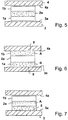
- FIG 5 the state after the complete liquefaction of the adhesive material A and the loosening of the adhesive connections to the components 3 and 4 is shown.
- the carrier layers 1a, 1b are largely free of the adhesive material A which has been absorbed into the absorption layer 2a. Between the carrier layers 1a, 1b and the component surfaces 3a, 4a facing them, the adhesive material A has been removed from the first and second adhesive areas, and the adhesive connections have been released.
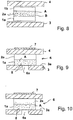
- FIGs 6, 7 , 8th a constellation with two different adhesive materials A, B is shown.
- the adhesive element consisting of the first carrier layer 1a, the second carrier layer 1b and the absorption layer 2a lying between these, is wetted with an adhesive material B in the area of the first carrier layer 1a, while the second carrier layer 1b is wetted with the adhesive material A.
- the first carrier layer 1a is glued to the component surface 3a by means of the adhesive material B
- the second carrier layer 1b is glued to the component surface 4a by means of the adhesive material A.
- the adhesive materials A, B can change into the liquid state in particular at different temperatures. In this way it is possible to first liquefy a first adhesive material, for example the adhesive material A, by controlling the temperature, while the adhesive material B still remains solid.
- a first adhesive material for example the adhesive material A
- the second carrier layer 1b is thus free of adhesive material, and the bond between the second carrier layer 1b and the component surface 4a is released. In this state, the adhesive element 1 a, 1 b, 2 a is still glued to the component 3 on the component surface 3 a.
- the adhesive element 1a, 1b, 2a can also be designed in this case either as a layering of three different substances or the same substances with different properties, the carrier layers 1a, 1b, for example, being made of the same material and being provided with the same composition.
- the material and / or nature of the carrier layers 1a, 1b can also be different.
- the material of the absorption layer 2a can differ from the material of one or both carrier layers 1a, 1b, but the material of the absorption layer 2a can also be identical to at least one of the carrier layers 1a, 1b. In this case, the nature, for example the porosity, of the absorption layer 2a must differ from that of the carrier layers 1a, 1b.
- a gradual transition between the carrier layer 1a, the absorption layer 2a and the carrier layer 1b is formed by material mixing. This can be done by appropriate manufacturing processes and mixing of the manufacturing materials, or only the properties of the various layers can be different and merge into one another through a constant change in parameters. For example, there can be a steady transition in the porosity from the first carrier layer 1a to the middle of the absorption layer 2a and from there to the second carrier layer 1b. This possibility of continuous transitions of properties and / or material mixtures between the different layers is given for all exemplary embodiments.
- Figure 9 shows, as well as the Figures 10 and 11 discloses a valve assembly using an adhesive element, the adhesive element as in FIGS Figures 1 to 3 made of a first carrier layer 1a and an absorption layer 2a consists.
- a channel 6 is formed between the components 3 and 4, a channel opening 6a being provided.
- the channel opening 6a can for example be given by a bore in the component 3.
- the carrier layer 1a of the adhesive element is connected to the component surface 3a by means of an adhesive material A, the adhesive material, for example, being at least partially absorbed in the carrier layer 1a, as indicated by the dots in the cross-sectional illustration.
- the valve arrangement has an actuator 7 which liquefies the adhesive material and which can be mounted on the component 4 as a heating element, for example. If the temperature is increased by means of the actuator 7 in such a way that the adhesive material A liquefies, as in FIG Figure 10 shown, the adhesive material A is sucked into the absorption layer 2a and moves within the carrier layer 1a away from the component surface 3a. After a period of time, as in Figure 11 shown, the adhesive material A is completely or almost completely absorbed in the absorption layer 2a, so that the first carrier layer 1a is practically free of adhesive material, as is the adhesive area between the carrier layer 1a and the component surface 3a. This is due to a gap between the carrier layer 1a and the component surface 3a in FIG Figure 11 indicated.
- the valve arrangement is thus open.
- the temperature can be lowered again so that the adhesive material A remains in the absorption layer 2a and solidifies there, for example.
- the Figures 12 and 13 show another embodiment of a valve arrangement between a component 3 and a component 4, the carrier layer 1a this time being laterally surrounded by two absorption layers 2a, 2b. Both the carrier layer 1a and the absorption layers 2a, 2b extend completely between the first component 3 and the second component 4 and fill the distance between the component surface 3a and the component surface 4a.
- the carrier layer 1a is at least partially wetted with the adhesive material A, at least on its outside in the adhesive area between the carrier layer 1a and the component surface 3a, in particular in the area of the edge of the opening 6a on the component 3.
- the carrier layer 1a is with the adhesive material A. glued to the edge of the channel opening 6a and closes the channel opening 6a.
- a channel is provided between the components 3 and 4, which can be separated from the channel opening 6a by the valve arrangement and can be connected to the channel opening 6a by releasing the adhesive element.
- an actuator 7 is provided which can bring about a temperature increase of the adhesive element 1a, 2a, 2b.
- the actuator is operated and the adhesive material A liquefies, it is drawn into the first carrier layer 1a and further into the absorption layers 2a, 2b.
- the absorption layers 2a, 2b can consist of the same material, but also of different materials, and in both cases have the same or similar properties, but also different properties.
- the adhesive material A is essentially absorbed in one or both of the absorption layers, the carrier layer 1a is largely free of the adhesive material, as is the area between the first carrier layer 1a and the edge area of the channel opening 6a on the component 3 Gap shown between the carrier layer 1a and the component 3 in the area of the edge of the opening 6a.
- a fluid can now flow from the channel opening 6a into the channel / area between the components 3 and 4, so that the valve arrangement is opened by releasing the adhesive bond of the adhesive element 1a, 2a, 2b.
- the adhesive material A has been drawn through the first carrier layer 1a into the absorption layers 2a, 2b with practically no residue, there is no risk of the channel opening 6a being blocked by the liquefied adhesive material A when the adhesive connection is loosened. This is particularly important for very small channel openings 6a, such as when using such valve assemblies in the pharmaceutical sector, for example with metering assemblies, metering pumps, etc., the z. B. can also be implantable.
Landscapes
- Chemical & Material Sciences (AREA)
- Health & Medical Sciences (AREA)
- Organic Chemistry (AREA)
- Dispersion Chemistry (AREA)
- Hematology (AREA)
- General Health & Medical Sciences (AREA)
- Analytical Chemistry (AREA)
- Clinical Laboratory Science (AREA)
- Chemical Kinetics & Catalysis (AREA)
- Engineering & Computer Science (AREA)
- General Engineering & Computer Science (AREA)
- Mechanical Engineering (AREA)
- Adhesives Or Adhesive Processes (AREA)
- Application Of Or Painting With Fluid Materials (AREA)
- Adhesive Tapes (AREA)
Claims (14)
- Elément adhésif (1a, 1b, 2a, 2b) destiné à être collé sur au moins une surface de composant (3a, 4a), doté d'au moins une première couche de support (1a, 1b), qui porte au moins une couche d'un premier matériau adhésif (A, B) sur une première face avant dans une première zone adhésive (8) et qui est perméable au premier matériau adhésif, et doté d'au moins une couche d'absorption (2a, 2b) reliée avec la première couche de support (1a, 1b), où le matériau adhésif et la première couche support sont coordonnés l'un vis-à-vis de l'autre de telle manière que le premier matériau adhésif (A, B), lorsqu'il est présent sous forme liquide, est aspiré au moins partiellement par capillarité dans la première couche support (1a, 1b), et où la couche d'absorption (2a, 2b) est conçue de telle manière, qu'en raison de l'effet capillaire, elle est davantage mouillée par le premier matériau adhésif que la première couche support (1a, 1b).
- Elément adhésif selon la revendication 1, caractérisé en ce qu'il présente, en complément de la première couche de support (1a), une deuxième couche support (1b), qui présente sur une face extérieure dans une deuxième zone adhésive (9) une couche d'un deuxième matériau adhésifs (B), où la deuxième couche support (1b) est perméable pour le deuxième matériau adhésif (B) de sorte que le deuxième matériau adhésif, lorsqu'il se présente sous forme liquide, est aspiré au moins partiellement par capillarité dans la deuxième couche support (1b), où une couche d'absorption (2a, 2b) est reliée avec la deuxième couche support (1b), qui est plus fortement mouillée par le deuxième matériau adhésif (B) sous forme liquide que la deuxième couche support.
- Elément adhésif selon la revendication 2, caractérisé en ce que la deuxième couche support (1b) est reliée avec la même couche d'absorption (2a) que la première couche support.
- Elément adhésif selon la revendication 3, caractérisé en ce que la couche d'absorption (2a) commune est disposée entre la première couche de support (1a) et la deuxième couche support (1b).
- Elément adhésif selon la revendication 2 ou l'une des suivantes, caractérisé en ce que la deuxième couche support (1b) présente la même nature que la première couche support (1a), où la deuxième couche support est en particulier constituée du même matériau que la première couche support.
- Elément adhésif selon l'une des revendications 2 à 4, caractérisé en ce que la nature de la deuxième couche support (1b) est différente de celle de la première couche de support (1a), où la deuxième couche support est en particulier constituée d'un autre matériau que la première couche support.
- Elément adhésif selon la revendication 2 ou de l'une des suivantes, caractérisé en ce que le deuxième matériau adhésif (B) est identique au premier matériau adhésif (A).
- Elément adhésif selon l'une des revendications 2 à 6, caractérisé en ce que le deuxième matériau adhésif (A) est différent du premier matériau adhésif (B).
- Elément adhésif selon la revendication 2 ou de l'une des suivantes, caractérisé en ce que le matériau de la couche d'absorption (2b) reliée avec la deuxième couche support (1b) est différent du matériau de la couche d'absorption (2a) reliée à la première couche de support (1a).
- Elément adhésif selon l'une des revendications 2 à 9, caractérisé en ce que le matériau de la couche d'absorption (2b) reliée avec la deuxième couche support (1b) est identique au matériau de la couche d'absorption (2a) reliée à la première couche de support (1a).
- Elément adhésif selon la revendication 1 ou de l'une des suivantes, caractérisé en ce qu'au moins une couche d'absorption (2a, 2b) est constituée du même matériau qu'une couche support (1a, 1b) reliée avec celle-ci et qu'en particulier la couche d'absorption est différente par un paramètre de structure, notamment une taille de pores moyenne, de la couche support.
- Elément adhésif selon la revendication 11, caractérisé en ce que le paramètre de structure se modifie de manière continue ou par étapes avec un écart croissant par rapport à la couche support dans la couche d'absorption (2a, 2b), en partant de la limite de la couche support (1a, 1b).
- Elément adhésif selon la revendication 12, caractérisé en ce que la valeur du paramètre de structure dans la couche d'absorption (2a, 2b) à la limite de la couche support (1a, 1b) correspond au paramètre équivalent dans la couche support, de sorte que la transition du paramètre de structure s'y effectue de manière continue.
- Système de soupape avec au moins un orifice de canal (6a), qui est fermé par un élément adhésif (1a, 1b, 2a, 2b) selon l'une des revendications 1 à 13 collé sur le bord de l'orifice de canal.
Applications Claiming Priority (1)
| Application Number | Priority Date | Filing Date | Title |
|---|---|---|---|
| DE102016217241.7A DE102016217241A1 (de) | 2016-09-09 | 2016-09-09 | Klebeelement und Ventilanordnung |
Publications (2)
| Publication Number | Publication Date |
|---|---|
| EP3293239A1 EP3293239A1 (fr) | 2018-03-14 |
| EP3293239B1 true EP3293239B1 (fr) | 2020-11-11 |
Family
ID=59901349
Family Applications (1)
| Application Number | Title | Priority Date | Filing Date |
|---|---|---|---|
| EP17190062.4A Not-in-force EP3293239B1 (fr) | 2016-09-09 | 2017-09-08 | Élément adhésif et ensemble de soupape |
Country Status (2)
| Country | Link |
|---|---|
| EP (1) | EP3293239B1 (fr) |
| DE (1) | DE102016217241A1 (fr) |
Family Cites Families (6)
| Publication number | Priority date | Publication date | Assignee | Title |
|---|---|---|---|---|
| FR2856046B1 (fr) | 2003-06-16 | 2005-07-29 | Biomerieux Sa | Microvanne fluidique a ouverture par commande electrique |
| JP5057968B2 (ja) * | 2004-05-10 | 2012-10-24 | ザ エアロスペース コーポレーション | 分離可能な操作モジュールおよび流体保持モジュールを有するマイクロ流体装置 |
| US7694694B2 (en) * | 2004-05-10 | 2010-04-13 | The Aerospace Corporation | Phase-change valve apparatuses |
| KR100738113B1 (ko) | 2006-05-10 | 2007-07-12 | 삼성전자주식회사 | 상전이형 밸브 및 그 제작방법 |
| EP2328694A2 (fr) * | 2008-09-08 | 2011-06-08 | Eastman Chemical Company | Stratifiés de psa lavables |
| GB2467298A (en) * | 2009-01-23 | 2010-07-28 | Univ Dublin City | Multilayer microfluidic device |
-
2016
- 2016-09-09 DE DE102016217241.7A patent/DE102016217241A1/de not_active Ceased
-
2017
- 2017-09-08 EP EP17190062.4A patent/EP3293239B1/fr not_active Not-in-force
Non-Patent Citations (1)
| Title |
|---|
| None * |
Also Published As
| Publication number | Publication date |
|---|---|
| DE102016217241A1 (de) | 2018-03-15 |
| EP3293239A1 (fr) | 2018-03-14 |
Similar Documents
| Publication | Publication Date | Title |
|---|---|---|
| DE602004002407T2 (de) | Mikrofluidventil mit elektrischer öffnungssteuerung | |
| AT511113B1 (de) | Verfahren zur herstellung eines faserverbundbauteils und werkzeuganordnung hierfür | |
| DE1642808C3 (de) | Membranschichtkörper für Flüssigkeitstrenngeräte | |
| EP1452143A2 (fr) | Ciseaux, notamment à usage chirurgical | |
| EP2783752B1 (fr) | Vanne normalment serrée pour composants microfluidiques de couches aux polymères et procédé | |
| DE102009005874A1 (de) | Ventil, insbesondere für ein Bauelement der Mikrofluidtechnik | |
| DE1774321C3 (de) | Verfahren zur Herstellung des Rückspaltes eines Magnetkopfes | |
| DE102008028864B4 (de) | Klebetechnische Anbindung von Faltwabenkernen in Sandwichstrukturen, Vorrichtung sowie Verwendung | |
| DE102008008198A1 (de) | Mehrlagiges faserverstärktes Thermoplast-Flachmaterial sowie Verfahren zu seiner Herstellung | |
| DE102014222818A1 (de) | Elektronik-Sandwichstruktur mit zwei mittels einer Sinterschicht zusammengesinterten Fügepartnern | |
| EP3111115B1 (fr) | Procédé de fabrication d'un élément fonctionnel pour joints plats ainsi qu'élément fonctionnel pour joints plats | |
| DE2038080B2 (de) | Verfahren zum Verkleben von Werk stucken aus Ferrit | |
| DE102008048064A1 (de) | Mikrofluidisches Ventil, mikrofluidische Pumpe, mikrofluidisches System und ein Herstellungsverfahren | |
| EP3293239A1 (fr) | Élément adhésif et ensemble de soupape | |
| DE102012223871B4 (de) | Verfahren für die Vorbereitung eines Halbzeugs aus Fasermaterial auf ein Nasspressverfahren sowie Vorbereitungsvorrichtung für die Vorbereitung eines Halbzeugs aus Fasermaterial auf ein Nasspressverfahren | |
| EP4017697B1 (fr) | Procédé de production d'un composant structurel | |
| DE102009002631A1 (de) | Piezoelektrischer Antrieb und Mikroventil mit einem solchen | |
| DE10335492B4 (de) | Verfahren zum selektiven Verbinden von mikrostrukturierten Teilen | |
| DE19646184A1 (de) | Verfahren zum Herstellen einer Chipkarte und Vorrichtung zum Durchführen des Verfahrens | |
| EP2759751A2 (fr) | Procédé de fabrication d'un clapet anti-retour fermé-normal pour des composants microfluidiques à partir d'un système stratifié polymère et clapet anti-retour | |
| DE102004033440A1 (de) | Mikrostrukturierte Vorrichtung und Verfahren zu ihrer Herstellung | |
| EP1700036B1 (fr) | Micropompe et son procédé de fabrication | |
| EP1663509B1 (fr) | Corps de reglage pour regler la largeur de passage d'un interstice de dosage | |
| AT523450B1 (de) | Durchdringbares Element | |
| DE102020120214B4 (de) | Filterelement mit Klebstoffstreifen |
Legal Events
| Date | Code | Title | Description |
|---|---|---|---|
| PUAI | Public reference made under article 153(3) epc to a published international application that has entered the european phase |
Free format text: ORIGINAL CODE: 0009012 |
|
| STAA | Information on the status of an ep patent application or granted ep patent |
Free format text: STATUS: THE APPLICATION HAS BEEN PUBLISHED |
|
| AK | Designated contracting states |
Kind code of ref document: A1 Designated state(s): AL AT BE BG CH CY CZ DE DK EE ES FI FR GB GR HR HU IE IS IT LI LT LU LV MC MK MT NL NO PL PT RO RS SE SI SK SM TR |
|
| AX | Request for extension of the european patent |
Extension state: BA ME |
|
| STAA | Information on the status of an ep patent application or granted ep patent |
Free format text: STATUS: REQUEST FOR EXAMINATION WAS MADE |
|
| 17P | Request for examination filed |
Effective date: 20180907 |
|
| RBV | Designated contracting states (corrected) |
Designated state(s): AL AT BE BG CH CY CZ DE DK EE ES FI FR GB GR HR HU IE IS IT LI LT LU LV MC MK MT NL NO PL PT RO RS SE SI SK SM TR |
|
| REG | Reference to a national code |
Ref country code: DE Ref legal event code: R079 Ref document number: 502017008126 Country of ref document: DE Free format text: PREVIOUS MAIN CLASS: C09J0007000000 Ipc: C09J0007260000 |
|
| GRAP | Despatch of communication of intention to grant a patent |
Free format text: ORIGINAL CODE: EPIDOSNIGR1 |
|
| STAA | Information on the status of an ep patent application or granted ep patent |
Free format text: STATUS: GRANT OF PATENT IS INTENDED |
|
| RIC1 | Information provided on ipc code assigned before grant |
Ipc: C09J 7/26 20180101AFI20200226BHEP Ipc: B01L 3/00 20060101ALI20200226BHEP Ipc: F16K 99/00 20060101ALI20200226BHEP Ipc: C09J 5/00 20060101ALI20200226BHEP Ipc: C09J 7/29 20180101ALI20200226BHEP |
|
| INTG | Intention to grant announced |
Effective date: 20200319 |
|
| GRAS | Grant fee paid |
Free format text: ORIGINAL CODE: EPIDOSNIGR3 |
|
| GRAA | (expected) grant |
Free format text: ORIGINAL CODE: 0009210 |
|
| STAA | Information on the status of an ep patent application or granted ep patent |
Free format text: STATUS: THE PATENT HAS BEEN GRANTED |
|
| AK | Designated contracting states |
Kind code of ref document: B1 Designated state(s): AL AT BE BG CH CY CZ DE DK EE ES FI FR GB GR HR HU IE IS IT LI LT LU LV MC MK MT NL NO PL PT RO RS SE SI SK SM TR |
|
| REG | Reference to a national code |
Ref country code: GB Ref legal event code: FG4D Free format text: NOT ENGLISH |
|
| REG | Reference to a national code |
Ref country code: CH Ref legal event code: EP |
|
| REG | Reference to a national code |
Ref country code: AT Ref legal event code: REF Ref document number: 1333460 Country of ref document: AT Kind code of ref document: T Effective date: 20201115 |
|
| REG | Reference to a national code |
Ref country code: DE Ref legal event code: R096 Ref document number: 502017008126 Country of ref document: DE |
|
| REG | Reference to a national code |
Ref country code: IE Ref legal event code: FG4D Free format text: LANGUAGE OF EP DOCUMENT: GERMAN |
|
| REG | Reference to a national code |
Ref country code: NL Ref legal event code: MP Effective date: 20201111 |
|
| PG25 | Lapsed in a contracting state [announced via postgrant information from national office to epo] |
Ref country code: GR Free format text: LAPSE BECAUSE OF FAILURE TO SUBMIT A TRANSLATION OF THE DESCRIPTION OR TO PAY THE FEE WITHIN THE PRESCRIBED TIME-LIMIT Effective date: 20210212 Ref country code: FI Free format text: LAPSE BECAUSE OF FAILURE TO SUBMIT A TRANSLATION OF THE DESCRIPTION OR TO PAY THE FEE WITHIN THE PRESCRIBED TIME-LIMIT Effective date: 20201111 Ref country code: RS Free format text: LAPSE BECAUSE OF FAILURE TO SUBMIT A TRANSLATION OF THE DESCRIPTION OR TO PAY THE FEE WITHIN THE PRESCRIBED TIME-LIMIT Effective date: 20201111 Ref country code: PT Free format text: LAPSE BECAUSE OF FAILURE TO SUBMIT A TRANSLATION OF THE DESCRIPTION OR TO PAY THE FEE WITHIN THE PRESCRIBED TIME-LIMIT Effective date: 20210311 Ref country code: NO Free format text: LAPSE BECAUSE OF FAILURE TO SUBMIT A TRANSLATION OF THE DESCRIPTION OR TO PAY THE FEE WITHIN THE PRESCRIBED TIME-LIMIT Effective date: 20210211 |
|
| PG25 | Lapsed in a contracting state [announced via postgrant information from national office to epo] |
Ref country code: SE Free format text: LAPSE BECAUSE OF FAILURE TO SUBMIT A TRANSLATION OF THE DESCRIPTION OR TO PAY THE FEE WITHIN THE PRESCRIBED TIME-LIMIT Effective date: 20201111 Ref country code: BG Free format text: LAPSE BECAUSE OF FAILURE TO SUBMIT A TRANSLATION OF THE DESCRIPTION OR TO PAY THE FEE WITHIN THE PRESCRIBED TIME-LIMIT Effective date: 20210211 Ref country code: LV Free format text: LAPSE BECAUSE OF FAILURE TO SUBMIT A TRANSLATION OF THE DESCRIPTION OR TO PAY THE FEE WITHIN THE PRESCRIBED TIME-LIMIT Effective date: 20201111 Ref country code: PL Free format text: LAPSE BECAUSE OF FAILURE TO SUBMIT A TRANSLATION OF THE DESCRIPTION OR TO PAY THE FEE WITHIN THE PRESCRIBED TIME-LIMIT Effective date: 20201111 Ref country code: IS Free format text: LAPSE BECAUSE OF FAILURE TO SUBMIT A TRANSLATION OF THE DESCRIPTION OR TO PAY THE FEE WITHIN THE PRESCRIBED TIME-LIMIT Effective date: 20210311 |
|
| REG | Reference to a national code |
Ref country code: LT Ref legal event code: MG9D |
|
| PG25 | Lapsed in a contracting state [announced via postgrant information from national office to epo] |
Ref country code: HR Free format text: LAPSE BECAUSE OF FAILURE TO SUBMIT A TRANSLATION OF THE DESCRIPTION OR TO PAY THE FEE WITHIN THE PRESCRIBED TIME-LIMIT Effective date: 20201111 |
|
| PG25 | Lapsed in a contracting state [announced via postgrant information from national office to epo] |
Ref country code: SK Free format text: LAPSE BECAUSE OF FAILURE TO SUBMIT A TRANSLATION OF THE DESCRIPTION OR TO PAY THE FEE WITHIN THE PRESCRIBED TIME-LIMIT Effective date: 20201111 Ref country code: RO Free format text: LAPSE BECAUSE OF FAILURE TO SUBMIT A TRANSLATION OF THE DESCRIPTION OR TO PAY THE FEE WITHIN THE PRESCRIBED TIME-LIMIT Effective date: 20201111 Ref country code: CZ Free format text: LAPSE BECAUSE OF FAILURE TO SUBMIT A TRANSLATION OF THE DESCRIPTION OR TO PAY THE FEE WITHIN THE PRESCRIBED TIME-LIMIT Effective date: 20201111 Ref country code: EE Free format text: LAPSE BECAUSE OF FAILURE TO SUBMIT A TRANSLATION OF THE DESCRIPTION OR TO PAY THE FEE WITHIN THE PRESCRIBED TIME-LIMIT Effective date: 20201111 Ref country code: SM Free format text: LAPSE BECAUSE OF FAILURE TO SUBMIT A TRANSLATION OF THE DESCRIPTION OR TO PAY THE FEE WITHIN THE PRESCRIBED TIME-LIMIT Effective date: 20201111 Ref country code: LT Free format text: LAPSE BECAUSE OF FAILURE TO SUBMIT A TRANSLATION OF THE DESCRIPTION OR TO PAY THE FEE WITHIN THE PRESCRIBED TIME-LIMIT Effective date: 20201111 |
|
| REG | Reference to a national code |
Ref country code: DE Ref legal event code: R097 Ref document number: 502017008126 Country of ref document: DE |
|
| PG25 | Lapsed in a contracting state [announced via postgrant information from national office to epo] |
Ref country code: DK Free format text: LAPSE BECAUSE OF FAILURE TO SUBMIT A TRANSLATION OF THE DESCRIPTION OR TO PAY THE FEE WITHIN THE PRESCRIBED TIME-LIMIT Effective date: 20201111 |
|
| PLBE | No opposition filed within time limit |
Free format text: ORIGINAL CODE: 0009261 |
|
| STAA | Information on the status of an ep patent application or granted ep patent |
Free format text: STATUS: NO OPPOSITION FILED WITHIN TIME LIMIT |
|
| 26N | No opposition filed |
Effective date: 20210812 |
|
| PG25 | Lapsed in a contracting state [announced via postgrant information from national office to epo] |
Ref country code: NL Free format text: LAPSE BECAUSE OF FAILURE TO SUBMIT A TRANSLATION OF THE DESCRIPTION OR TO PAY THE FEE WITHIN THE PRESCRIBED TIME-LIMIT Effective date: 20201111 Ref country code: AL Free format text: LAPSE BECAUSE OF FAILURE TO SUBMIT A TRANSLATION OF THE DESCRIPTION OR TO PAY THE FEE WITHIN THE PRESCRIBED TIME-LIMIT Effective date: 20201111 |
|
| PG25 | Lapsed in a contracting state [announced via postgrant information from national office to epo] |
Ref country code: SI Free format text: LAPSE BECAUSE OF FAILURE TO SUBMIT A TRANSLATION OF THE DESCRIPTION OR TO PAY THE FEE WITHIN THE PRESCRIBED TIME-LIMIT Effective date: 20201111 |
|
| PG25 | Lapsed in a contracting state [announced via postgrant information from national office to epo] |
Ref country code: ES Free format text: LAPSE BECAUSE OF FAILURE TO SUBMIT A TRANSLATION OF THE DESCRIPTION OR TO PAY THE FEE WITHIN THE PRESCRIBED TIME-LIMIT Effective date: 20201111 |
|
| REG | Reference to a national code |
Ref country code: CH Ref legal event code: PL |
|
| REG | Reference to a national code |
Ref country code: BE Ref legal event code: MM Effective date: 20210930 |
|
| PG25 | Lapsed in a contracting state [announced via postgrant information from national office to epo] |
Ref country code: IS Free format text: LAPSE BECAUSE OF FAILURE TO SUBMIT A TRANSLATION OF THE DESCRIPTION OR TO PAY THE FEE WITHIN THE PRESCRIBED TIME-LIMIT Effective date: 20210311 Ref country code: MC Free format text: LAPSE BECAUSE OF FAILURE TO SUBMIT A TRANSLATION OF THE DESCRIPTION OR TO PAY THE FEE WITHIN THE PRESCRIBED TIME-LIMIT Effective date: 20201111 |
|
| PG25 | Lapsed in a contracting state [announced via postgrant information from national office to epo] |
Ref country code: LU Free format text: LAPSE BECAUSE OF NON-PAYMENT OF DUE FEES Effective date: 20210908 Ref country code: IE Free format text: LAPSE BECAUSE OF NON-PAYMENT OF DUE FEES Effective date: 20210908 Ref country code: BE Free format text: LAPSE BECAUSE OF NON-PAYMENT OF DUE FEES Effective date: 20210930 |
|
| PG25 | Lapsed in a contracting state [announced via postgrant information from national office to epo] |
Ref country code: LI Free format text: LAPSE BECAUSE OF NON-PAYMENT OF DUE FEES Effective date: 20210930 Ref country code: CH Free format text: LAPSE BECAUSE OF NON-PAYMENT OF DUE FEES Effective date: 20210930 |
|
| PG25 | Lapsed in a contracting state [announced via postgrant information from national office to epo] |
Ref country code: HU Free format text: LAPSE BECAUSE OF FAILURE TO SUBMIT A TRANSLATION OF THE DESCRIPTION OR TO PAY THE FEE WITHIN THE PRESCRIBED TIME-LIMIT; INVALID AB INITIO Effective date: 20170908 |
|
| P01 | Opt-out of the competence of the unified patent court (upc) registered |
Effective date: 20230524 |
|
| PG25 | Lapsed in a contracting state [announced via postgrant information from national office to epo] |
Ref country code: CY Free format text: LAPSE BECAUSE OF FAILURE TO SUBMIT A TRANSLATION OF THE DESCRIPTION OR TO PAY THE FEE WITHIN THE PRESCRIBED TIME-LIMIT Effective date: 20201111 |
|
| PGFP | Annual fee paid to national office [announced via postgrant information from national office to epo] |
Ref country code: GB Payment date: 20230921 Year of fee payment: 7 |
|
| REG | Reference to a national code |
Ref country code: AT Ref legal event code: MM01 Ref document number: 1333460 Country of ref document: AT Kind code of ref document: T Effective date: 20220908 |
|
| PGFP | Annual fee paid to national office [announced via postgrant information from national office to epo] |
Ref country code: FR Payment date: 20230918 Year of fee payment: 7 Ref country code: DE Payment date: 20230919 Year of fee payment: 7 |
|
| PG25 | Lapsed in a contracting state [announced via postgrant information from national office to epo] |
Ref country code: AT Free format text: LAPSE BECAUSE OF NON-PAYMENT OF DUE FEES Effective date: 20220908 |
|
| PGFP | Annual fee paid to national office [announced via postgrant information from national office to epo] |
Ref country code: IT Payment date: 20230929 Year of fee payment: 7 |
|
| PG25 | Lapsed in a contracting state [announced via postgrant information from national office to epo] |
Ref country code: MK Free format text: LAPSE BECAUSE OF FAILURE TO SUBMIT A TRANSLATION OF THE DESCRIPTION OR TO PAY THE FEE WITHIN THE PRESCRIBED TIME-LIMIT Effective date: 20201111 |
|
| PG25 | Lapsed in a contracting state [announced via postgrant information from national office to epo] |
Ref country code: TR Free format text: LAPSE BECAUSE OF FAILURE TO SUBMIT A TRANSLATION OF THE DESCRIPTION OR TO PAY THE FEE WITHIN THE PRESCRIBED TIME-LIMIT Effective date: 20201111 |
|
| PG25 | Lapsed in a contracting state [announced via postgrant information from national office to epo] |
Ref country code: MT Free format text: LAPSE BECAUSE OF FAILURE TO SUBMIT A TRANSLATION OF THE DESCRIPTION OR TO PAY THE FEE WITHIN THE PRESCRIBED TIME-LIMIT Effective date: 20201111 |
|
| REG | Reference to a national code |
Ref country code: DE Ref legal event code: R119 Ref document number: 502017008126 Country of ref document: DE |
|
| GBPC | Gb: european patent ceased through non-payment of renewal fee |
Effective date: 20240908 |
|
| PG25 | Lapsed in a contracting state [announced via postgrant information from national office to epo] |
Ref country code: DE Free format text: LAPSE BECAUSE OF NON-PAYMENT OF DUE FEES Effective date: 20250401 |
|
| PG25 | Lapsed in a contracting state [announced via postgrant information from national office to epo] |
Ref country code: GB Free format text: LAPSE BECAUSE OF NON-PAYMENT OF DUE FEES Effective date: 20240908 |
|
| PG25 | Lapsed in a contracting state [announced via postgrant information from national office to epo] |
Ref country code: IT Free format text: LAPSE BECAUSE OF NON-PAYMENT OF DUE FEES Effective date: 20240908 |
|
| PG25 | Lapsed in a contracting state [announced via postgrant information from national office to epo] |
Ref country code: FR Free format text: LAPSE BECAUSE OF NON-PAYMENT OF DUE FEES Effective date: 20240930 |