EP3293239B1 - Adhesive element and valve assembly - Google Patents
Adhesive element and valve assembly Download PDFInfo
- Publication number
- EP3293239B1 EP3293239B1 EP17190062.4A EP17190062A EP3293239B1 EP 3293239 B1 EP3293239 B1 EP 3293239B1 EP 17190062 A EP17190062 A EP 17190062A EP 3293239 B1 EP3293239 B1 EP 3293239B1
- Authority
- EP
- European Patent Office
- Prior art keywords
- carrier layer
- adhesive
- layer
- adhesive material
- carrier
- Prior art date
- Legal status (The legal status is an assumption and is not a legal conclusion. Google has not performed a legal analysis and makes no representation as to the accuracy of the status listed.)
- Not-in-force
Links
Images


Classifications
-
- C—CHEMISTRY; METALLURGY
- C09—DYES; PAINTS; POLISHES; NATURAL RESINS; ADHESIVES; COMPOSITIONS NOT OTHERWISE PROVIDED FOR; APPLICATIONS OF MATERIALS NOT OTHERWISE PROVIDED FOR
- C09J—ADHESIVES; NON-MECHANICAL ASPECTS OF ADHESIVE PROCESSES IN GENERAL; ADHESIVE PROCESSES NOT PROVIDED FOR ELSEWHERE; USE OF MATERIALS AS ADHESIVES
- C09J5/00—Adhesive processes in general; Adhesive processes not provided for elsewhere, e.g. relating to primers
-
- B—PERFORMING OPERATIONS; TRANSPORTING
- B01—PHYSICAL OR CHEMICAL PROCESSES OR APPARATUS IN GENERAL
- B01L—CHEMICAL OR PHYSICAL LABORATORY APPARATUS FOR GENERAL USE
- B01L3/00—Containers or dishes for laboratory use, e.g. laboratory glassware; Droppers
- B01L3/50—Containers for the purpose of retaining a material to be analysed, e.g. test tubes
- B01L3/502—Containers for the purpose of retaining a material to be analysed, e.g. test tubes with fluid transport, e.g. in multi-compartment structures
- B01L3/5027—Containers for the purpose of retaining a material to be analysed, e.g. test tubes with fluid transport, e.g. in multi-compartment structures by integrated microfluidic structures, i.e. dimensions of channels and chambers are such that surface tension forces are important, e.g. lab-on-a-chip
- B01L3/502707—Containers for the purpose of retaining a material to be analysed, e.g. test tubes with fluid transport, e.g. in multi-compartment structures by integrated microfluidic structures, i.e. dimensions of channels and chambers are such that surface tension forces are important, e.g. lab-on-a-chip characterised by the manufacture of the container or its components
-
- B—PERFORMING OPERATIONS; TRANSPORTING
- B01—PHYSICAL OR CHEMICAL PROCESSES OR APPARATUS IN GENERAL
- B01L—CHEMICAL OR PHYSICAL LABORATORY APPARATUS FOR GENERAL USE
- B01L3/00—Containers or dishes for laboratory use, e.g. laboratory glassware; Droppers
- B01L3/50—Containers for the purpose of retaining a material to be analysed, e.g. test tubes
- B01L3/502—Containers for the purpose of retaining a material to be analysed, e.g. test tubes with fluid transport, e.g. in multi-compartment structures
- B01L3/5027—Containers for the purpose of retaining a material to be analysed, e.g. test tubes with fluid transport, e.g. in multi-compartment structures by integrated microfluidic structures, i.e. dimensions of channels and chambers are such that surface tension forces are important, e.g. lab-on-a-chip
- B01L3/502738—Containers for the purpose of retaining a material to be analysed, e.g. test tubes with fluid transport, e.g. in multi-compartment structures by integrated microfluidic structures, i.e. dimensions of channels and chambers are such that surface tension forces are important, e.g. lab-on-a-chip characterised by integrated valves
-
- C—CHEMISTRY; METALLURGY
- C09—DYES; PAINTS; POLISHES; NATURAL RESINS; ADHESIVES; COMPOSITIONS NOT OTHERWISE PROVIDED FOR; APPLICATIONS OF MATERIALS NOT OTHERWISE PROVIDED FOR
- C09J—ADHESIVES; NON-MECHANICAL ASPECTS OF ADHESIVE PROCESSES IN GENERAL; ADHESIVE PROCESSES NOT PROVIDED FOR ELSEWHERE; USE OF MATERIALS AS ADHESIVES
- C09J7/00—Adhesives in the form of films or foils
- C09J7/20—Adhesives in the form of films or foils characterised by their carriers
- C09J7/22—Plastics; Metallised plastics
- C09J7/26—Porous or cellular plastics
-
- C—CHEMISTRY; METALLURGY
- C09—DYES; PAINTS; POLISHES; NATURAL RESINS; ADHESIVES; COMPOSITIONS NOT OTHERWISE PROVIDED FOR; APPLICATIONS OF MATERIALS NOT OTHERWISE PROVIDED FOR
- C09J—ADHESIVES; NON-MECHANICAL ASPECTS OF ADHESIVE PROCESSES IN GENERAL; ADHESIVE PROCESSES NOT PROVIDED FOR ELSEWHERE; USE OF MATERIALS AS ADHESIVES
- C09J7/00—Adhesives in the form of films or foils
- C09J7/20—Adhesives in the form of films or foils characterised by their carriers
- C09J7/29—Laminated material
-
- F—MECHANICAL ENGINEERING; LIGHTING; HEATING; WEAPONS; BLASTING
- F16—ENGINEERING ELEMENTS AND UNITS; GENERAL MEASURES FOR PRODUCING AND MAINTAINING EFFECTIVE FUNCTIONING OF MACHINES OR INSTALLATIONS; THERMAL INSULATION IN GENERAL
- F16K—VALVES; TAPS; COCKS; ACTUATING-FLOATS; DEVICES FOR VENTING OR AERATING
- F16K99/00—Subject matter not provided for in other groups of this subclass
- F16K99/0001—Microvalves
- F16K99/0034—Operating means specially adapted for microvalves
- F16K99/0042—Electric operating means therefor
- F16K99/0044—Electric operating means therefor using thermo-electric means
-
- B—PERFORMING OPERATIONS; TRANSPORTING
- B01—PHYSICAL OR CHEMICAL PROCESSES OR APPARATUS IN GENERAL
- B01L—CHEMICAL OR PHYSICAL LABORATORY APPARATUS FOR GENERAL USE
- B01L2300/00—Additional constructional details
- B01L2300/08—Geometry, shape and general structure
- B01L2300/0887—Laminated structure
-
- B—PERFORMING OPERATIONS; TRANSPORTING
- B01—PHYSICAL OR CHEMICAL PROCESSES OR APPARATUS IN GENERAL
- B01L—CHEMICAL OR PHYSICAL LABORATORY APPARATUS FOR GENERAL USE
- B01L2400/00—Moving or stopping fluids
- B01L2400/06—Valves, specific forms thereof
- B01L2400/0677—Valves, specific forms thereof phase change valves; Meltable, freezing, dissolvable plugs; Destructible barriers
-
- C—CHEMISTRY; METALLURGY
- C09—DYES; PAINTS; POLISHES; NATURAL RESINS; ADHESIVES; COMPOSITIONS NOT OTHERWISE PROVIDED FOR; APPLICATIONS OF MATERIALS NOT OTHERWISE PROVIDED FOR
- C09J—ADHESIVES; NON-MECHANICAL ASPECTS OF ADHESIVE PROCESSES IN GENERAL; ADHESIVE PROCESSES NOT PROVIDED FOR ELSEWHERE; USE OF MATERIALS AS ADHESIVES
- C09J2301/00—Additional features of adhesives in the form of films or foils
- C09J2301/50—Additional features of adhesives in the form of films or foils characterized by process specific features
- C09J2301/502—Additional features of adhesives in the form of films or foils characterized by process specific features process for debonding adherents
-
- F—MECHANICAL ENGINEERING; LIGHTING; HEATING; WEAPONS; BLASTING
- F16—ENGINEERING ELEMENTS AND UNITS; GENERAL MEASURES FOR PRODUCING AND MAINTAINING EFFECTIVE FUNCTIONING OF MACHINES OR INSTALLATIONS; THERMAL INSULATION IN GENERAL
- F16K—VALVES; TAPS; COCKS; ACTUATING-FLOATS; DEVICES FOR VENTING OR AERATING
- F16K99/00—Subject matter not provided for in other groups of this subclass
- F16K2099/0073—Fabrication methods specifically adapted for microvalves
- F16K2099/008—Multi-layer fabrications
Definitions
- the invention is in the field of mechanics and joining technology and can be used with particular advantage in the field of microfluidics, but also in other fields.
- One of the most common joining techniques for connecting different components is gluing using an adhesive.
- a particular challenge here is to create releasable adhesive connections that can be released again without great effort, and in particular without damaging the connected components.
- a material component is often used that can be inactivated thermally or by radiation, in particular UV radiation.
- an adhesive can be liquefied by the action of temperature in order to break an adhesive connection.
- UV radiation can also make the adhesive brittle in order to break an adhesive bond.
- the swelling or expansion of certain constituents of the adhesive can also be achieved by heating and thereby indirectly loosening the adhesive connection.
- Openings can also be closed by gluing, so that the valve arrangement can be closed by gluing and opened again by loosening the glue.
- the WO 2005/111435 A2 deals with an arrangement for controlling fluid movements in a system of channels by means of microfluidics.
- the present invention is based on the object of creating an adhesive element which is easy to glue and the glueing of which can be solved easily and without problems.
- Claim 14 relates to a valve arrangement in which an adhesive element according to the invention is used.
- the invention relates to an adhesive element for gluing to at least one component surface, with at least one first carrier layer which carries a layer of a first adhesive material at least on a first outside in a first adhesive area and which is permeable to the first adhesive material, and with at least one absorption layer connected to the first carrier layer, the first adhesive material and the first carrier layer being coordinated with one another in such a way that the first adhesive material, when it is in liquid form, is at least partially sucked into the first carrier layer by capillary action, and the absorption layer is designed in this way that it is more heavily wetted by the liquid first adhesive material than the first carrier layer due to the capillary action.
- the first carrier layer can be glued to a component surface by means of the first adhesive material. At least in the first adhesive area, a surface of the first carrier layer is coated with the adhesive material, so that the first adhesive area is available for connection to the component surface. In this way, for example, an opening in the component surface, for example a channel, can be closed by gluing on the first carrier layer.
- the carrier layer can be formed by a solid and stiff material or also by a pliable layer.
- the liquefied first adhesive material wets the carrier layer, it can reach the absorption layer and be absorbed from there, the liquefied adhesive material being absorbed more strongly by the absorption layer than by the carrier layer in the contact area of the absorption layer with the first carrier layer, so that the Adhesive material is conveyed from the carrier layer into the absorption layer and thus away from the first adhesive area.
- the first adhesive material can be liquefied, for example, by increasing the temperature, but also by changing other physical parameters, for example by applying an electrical voltage or a magnetic field to change the viscosity, by the action of ultrasound or the action of UV radiation or another form of radiation.
- the adhesive element has, in addition to the first carrier layer, a second carrier layer which has a layer of a second adhesive material on an outside in a second adhesive area, the second carrier layer being permeable to the second adhesive material, such that the second adhesive material, if it is in liquid form, is at least partially sucked into the second carrier layer by capillary action, an absorption layer being connected to the second carrier layer, which is more wetted by the second adhesive material in liquefied form than the second carrier layer.
- the first and / or the second carrier layer can be designed to be porous or consist of a porous material, the pores being at least partially open. This can be achieved, for example, by using foamed, open-pored materials. Instead of bubble-like cavities, as in the case of a foamed material, channels (capillary channels) can also be provided in the material of one or more of the layers mentioned in order to achieve a capillary effect. These channels can be created during the production of the materials or also introduced or opened later.
- One or more of the layers can also be produced by sintering, for example.
- the material of which the carrier layer consists or the carrier layers and / or absorption layer (s) consist should in any case form a self-supporting framework, and preferably even if it absorbs liquefied adhesive, the layers should not change their volume / thickness.
- the individual layers, carrier layers as well as absorption layers can thus advantageously each have a sponge-like structure, form a self-supporting framework and also have a constant volume when absorbing adhesive.
- carrier layers and / or absorption layers can also consist of a nonwoven material and / or an absorbent fabric, for example a material consisting essentially of fiber sections or containing fiber sections, for example paper, or contain such a material.
- an adhesive element which has several adhesive areas, for example on different sides, for. B. can also be arranged on opposite sides of the adhesive element.
- an adhesive material is provided which can be liquefied and which can then be sucked into the respective carrier layer from the adhesive area. Since both carrier layers are connected with an absorption material, the adhesive material can be sucked further into the absorption layers so that the adhesive areas are largely free of the adhesive material after it has been released.
- the same adhesive material can be used for the two adhesive areas, but different adhesive materials can also be used for the different adhesive areas.
- the material of the carrier layers can also be different.
- a further embodiment of the invention provides that the second carrier layer is connected to the same absorption layer as the first carrier layer.
- the absorption layer can be connected to carrier layers on both sides and sandwiched between them. The absorption layer can then be in the center of the adhesive element and soak up the adhesive material in the liquid state through the carrier layers from different sides.
- a further embodiment of the invention can thus provide that the common absorption layer is arranged between the first carrier layer and the second carrier layer.
- the second carrier layer has the same composition as the first carrier layer, the second carrier layer in particular consisting of the same material as the first carrier layer.
- the nature of the second carrier layer is different from that of the first carrier layer, the second carrier layer in particular consisting of a different material than the first carrier layer.
- the adhesive element When using different carrier layers, the adhesive element can be designed in such a way that it has different adhesive properties in different adhesive areas and that the adhesive material thus has a different effect in the different adhesive areas. Even when the adhesive material liquefies, it can be sucked into the various carrier layers at different speeds and intensities.
- the second adhesive material is identical to the first adhesive material.
- the second adhesive material is different from the first adhesive material.
- the adhesive material can be removed simultaneously in the different adhesive areas, since it is subjected to the same physical conditions and is therefore liquefied at the different points of the adhesive element at approximately the same time. If different adhesive materials are used, then the first adhesive material can be liquefied in a targeted manner and the second adhesive material can be liquefied immediately thereafter or at a time interval later, thus loosening the adhesive points / adhesive areas. In this way, different adhesive points of an adhesive element can be released individually and independently of one another. Thus, only adhesive materials with different melting temperatures or with different physical parameters that lead to liquefaction have to be selected.
- the material of the absorption layer connected to the second carrier layer is different from the material of the absorption layer connected to the first carrier layer. In contrast to this, however, it can also be provided that the material of the absorption layer connected to the second carrier layer is identical to the material of the absorption layer connected to the first carrier layer.
- At least one absorption layer consists of the same material as a carrier layer connected to it and that in particular the absorption layer is distinguished from the carrier layer by a quality parameter, in particular a medium or a smallest or a largest pore size .
- the absorption layer is thus relatively similar to the or at least one carrier layer, but can differ from this in terms of a constitutional parameter which has the effect that the absorption layer is more strongly wetted by the liquefied adhesive material than the carrier layer.
- the material of the absorption layer can, however, be identical to the material of the carrier layer, so that only one other physical parameter, such as the porosity, can vary.
- condition parameter changes within the absorption layer, starting from the boundary to the carrier layer, continuously or in steps with increasing distance from the carrier layer.
- the value of the texture parameter in the absorption layer at the border to the carrier layer corresponds to the corresponding texture parameter in the carrier layer, so that the transition of the texture parameter is constant there.
- an adhesive element can be built up with a combined carrier and absorption layer, the wetting properties of the carrier layer changing with increasing distance from the or an adhesive area in such a way that the wetting with the liquefied adhesive material becomes stronger or the capillary effect becomes stronger, so that the Liquefied adhesive material is sucked by a material or texture gradient away from the adhesive area through some layers into other layers, which have a stronger tendency to be wetted with the adhesive material.
- the carrier material merges into the absorption material continuously or in discrete steps.
- the invention can also relate to a valve arrangement with an opening which is closed or closable by an adhesive element of the type explained above glued to the edge of the opening.
- a valve formed in this way has an opening that can be closed by an adhesive element and later unsealed. The liquefied adhesive material is removed as far as possible from the surface of the component to be bonded during liquefaction, so that openings on the component are not closed by adhesive material residues.
- Figure 1 shows a cross section of a component 3, on the component surface 3a of which an adhesive element 1a, 2a is glued in an adhesive area 8.
- the adhesive element has a first carrier layer 1a and an absorption layer 2a connected to it.
- the first carrier layer 1a carries an adhesive material A on its side facing the component surface 3a in a first adhesive area, ie at least in part of the contact surface between the first carrier layer 1a and the component 3.
- the adhesive material A can also be partially absorbed into the carrier layer 1a , as in Figure 1 is indicated by the partially dotted hatching. It can be provided, for example, that the first carrier layer 1 a is coated with the adhesive material before being glued to the component 3 and then placed on the component 3. Provision can be made for the adhesive material A to be partially liquefied for gluing, for example by the action of heat or by changing another physical parameter which has the effect of reversibly liquefying the adhesive material A.
- the adhesive element 1a, 2a is firmly connected to the component surface 3a.
- the first adhesive material A, the material C of the first carrier layer and the nature of the first carrier layer 1a are matched to one another in such a way that the adhesive material A wets the carrier layer 1a well and, for example, is partially absorbed or sucked into it.
- the first carrier layer 1 a can, for example, be designed to be porous or open-pored fine channels interspersed. The first adhesive material A can then be sucked into the carrier layer 1a by the capillary action.
- An absorption layer 2a is provided on the side of the first carrier layer 1a facing away from the component surface 3a and is at least partially in direct contact with the first carrier layer 1a.
- the absorption layer 2a, its material D and the nature of the absorption layer, for example the porosity, are designed in such a way that the wettability of the absorption layer 2a is greater than the wettability of the first carrier layer 1a. In this way, as soon as the adhesive material A is liquefied, it is practically completely sucked into the carrier layer 1a and transported from there further into the absorption layer 2a.
- Figure 2 This is detailed in Figure 2 shown in cross section, where the first adhesive material A has moved away from the component surface 3a and out of the first adhesive area 8 and is partly in the absorption layer 2a, partly still in the carrier layer 1a in the area labeled 5a.
- Figure 2 represents a transition state, since the adhesive material A is practically completely sucked into the absorption layer 2a due to the good wettability of the latter, as shown in FIG Figure 3 can be seen. There the adhesive material A in the area 5b is practically completely located in the absorption layer 2a.
- the adhesive material has almost completely withdrawn from the first carrier layer 1a, and also from the area between the carrier layer 1a and the component surface 3a (the first adhesive area), so that the adhesive connection between the component surface 3a and the carrier layer 1a is essentially dissolved.
- Figure 3 represented by the gap between the carrier layer 1a and the component surface 3a.
- the adhesive element 1a, 2a By liquefying the adhesive material A, the adhesive element 1a, 2a can thus be removed from the component surface 3a with practically no residue of adhesive material. All sensible physical parameter changes can be selected for the liquefaction of the adhesive material A, whereby for most substances the liquefaction by supplying heat is the easiest possible. However, it can also be influenced by a suitable choice of material the viscosity of a liquid adhesive A can be influenced as desired by magnetic and electric fields.
- the absorption layer 2a is shown separated from the first carrier layer 1a.
- the carrier layer can each consist of a first material C, while the absorption layer consists of a second material D.
- the two materials C and D can, however, also be identical, only the nature, for example the porosity, being selected differently in the first carrier layer and the absorption layer. It is decisive that the wettability of the absorption layer with the adhesive material A is greater than or equal to the wettability of the carrier layer 1a. The wettability can practically be described by the so-called spreading parameter.
- the spreading factor should therefore be greater for the absorption layer in connection with the liquefied adhesive material A than for the carrier layer in connection with the liquefied adhesive material.
- the present application speaks of greater or better wettability of the absorption layer with the adhesive material A.
- Figure 4 shows an adhesive element 1a, 2a, 1b glued on both sides to component surfaces 3a, 4a of components 3, 4.
- the adhesive element consists of a first carrier layer 1a, which faces the component 3 and is glued to the component surface 3a, a second carrier layer 1b, which faces the second component 4 and is glued to the component surface 4a, and one between the carrier layers 1a, 1b arranged absorption layer 2a.
- the absorption layer 2a has a better wettability with the adhesive material A than the carrier layers 1a, 1b.
- the carrier layers 1 a, 1 b are partially penetrated / wetted with the adhesive material A.
- the adhesive material A is also located at least in the first adhesive area 8 between the first carrier layer 1a and the component surface 3a and in the second adhesive area 9 between the second carrier layer 1b and the component surface 4a.
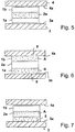
- FIG 5 the state after the complete liquefaction of the adhesive material A and the loosening of the adhesive connections to the components 3 and 4 is shown.
- the carrier layers 1a, 1b are largely free of the adhesive material A which has been absorbed into the absorption layer 2a. Between the carrier layers 1a, 1b and the component surfaces 3a, 4a facing them, the adhesive material A has been removed from the first and second adhesive areas, and the adhesive connections have been released.
- FIGs 6, 7 , 8th a constellation with two different adhesive materials A, B is shown.
- the adhesive element consisting of the first carrier layer 1a, the second carrier layer 1b and the absorption layer 2a lying between these, is wetted with an adhesive material B in the area of the first carrier layer 1a, while the second carrier layer 1b is wetted with the adhesive material A.
- the first carrier layer 1a is glued to the component surface 3a by means of the adhesive material B
- the second carrier layer 1b is glued to the component surface 4a by means of the adhesive material A.
- the adhesive materials A, B can change into the liquid state in particular at different temperatures. In this way it is possible to first liquefy a first adhesive material, for example the adhesive material A, by controlling the temperature, while the adhesive material B still remains solid.
- a first adhesive material for example the adhesive material A
- the second carrier layer 1b is thus free of adhesive material, and the bond between the second carrier layer 1b and the component surface 4a is released. In this state, the adhesive element 1 a, 1 b, 2 a is still glued to the component 3 on the component surface 3 a.
- the adhesive element 1a, 1b, 2a can also be designed in this case either as a layering of three different substances or the same substances with different properties, the carrier layers 1a, 1b, for example, being made of the same material and being provided with the same composition.
- the material and / or nature of the carrier layers 1a, 1b can also be different.
- the material of the absorption layer 2a can differ from the material of one or both carrier layers 1a, 1b, but the material of the absorption layer 2a can also be identical to at least one of the carrier layers 1a, 1b. In this case, the nature, for example the porosity, of the absorption layer 2a must differ from that of the carrier layers 1a, 1b.
- a gradual transition between the carrier layer 1a, the absorption layer 2a and the carrier layer 1b is formed by material mixing. This can be done by appropriate manufacturing processes and mixing of the manufacturing materials, or only the properties of the various layers can be different and merge into one another through a constant change in parameters. For example, there can be a steady transition in the porosity from the first carrier layer 1a to the middle of the absorption layer 2a and from there to the second carrier layer 1b. This possibility of continuous transitions of properties and / or material mixtures between the different layers is given for all exemplary embodiments.
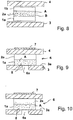
- Figure 9 shows, as well as the Figures 10 and 11 discloses a valve assembly using an adhesive element, the adhesive element as in FIGS Figures 1 to 3 made of a first carrier layer 1a and an absorption layer 2a consists.
- a channel 6 is formed between the components 3 and 4, a channel opening 6a being provided.
- the channel opening 6a can for example be given by a bore in the component 3.
- the carrier layer 1a of the adhesive element is connected to the component surface 3a by means of an adhesive material A, the adhesive material, for example, being at least partially absorbed in the carrier layer 1a, as indicated by the dots in the cross-sectional illustration.
- the valve arrangement has an actuator 7 which liquefies the adhesive material and which can be mounted on the component 4 as a heating element, for example. If the temperature is increased by means of the actuator 7 in such a way that the adhesive material A liquefies, as in FIG Figure 10 shown, the adhesive material A is sucked into the absorption layer 2a and moves within the carrier layer 1a away from the component surface 3a. After a period of time, as in Figure 11 shown, the adhesive material A is completely or almost completely absorbed in the absorption layer 2a, so that the first carrier layer 1a is practically free of adhesive material, as is the adhesive area between the carrier layer 1a and the component surface 3a. This is due to a gap between the carrier layer 1a and the component surface 3a in FIG Figure 11 indicated.
- the valve arrangement is thus open.
- the temperature can be lowered again so that the adhesive material A remains in the absorption layer 2a and solidifies there, for example.
- the Figures 12 and 13 show another embodiment of a valve arrangement between a component 3 and a component 4, the carrier layer 1a this time being laterally surrounded by two absorption layers 2a, 2b. Both the carrier layer 1a and the absorption layers 2a, 2b extend completely between the first component 3 and the second component 4 and fill the distance between the component surface 3a and the component surface 4a.
- the carrier layer 1a is at least partially wetted with the adhesive material A, at least on its outside in the adhesive area between the carrier layer 1a and the component surface 3a, in particular in the area of the edge of the opening 6a on the component 3.
- the carrier layer 1a is with the adhesive material A. glued to the edge of the channel opening 6a and closes the channel opening 6a.
- a channel is provided between the components 3 and 4, which can be separated from the channel opening 6a by the valve arrangement and can be connected to the channel opening 6a by releasing the adhesive element.
- an actuator 7 is provided which can bring about a temperature increase of the adhesive element 1a, 2a, 2b.
- the actuator is operated and the adhesive material A liquefies, it is drawn into the first carrier layer 1a and further into the absorption layers 2a, 2b.
- the absorption layers 2a, 2b can consist of the same material, but also of different materials, and in both cases have the same or similar properties, but also different properties.
- the adhesive material A is essentially absorbed in one or both of the absorption layers, the carrier layer 1a is largely free of the adhesive material, as is the area between the first carrier layer 1a and the edge area of the channel opening 6a on the component 3 Gap shown between the carrier layer 1a and the component 3 in the area of the edge of the opening 6a.
- a fluid can now flow from the channel opening 6a into the channel / area between the components 3 and 4, so that the valve arrangement is opened by releasing the adhesive bond of the adhesive element 1a, 2a, 2b.
- the adhesive material A has been drawn through the first carrier layer 1a into the absorption layers 2a, 2b with practically no residue, there is no risk of the channel opening 6a being blocked by the liquefied adhesive material A when the adhesive connection is loosened. This is particularly important for very small channel openings 6a, such as when using such valve assemblies in the pharmaceutical sector, for example with metering assemblies, metering pumps, etc., the z. B. can also be implantable.
Landscapes
- Chemical & Material Sciences (AREA)
- Health & Medical Sciences (AREA)
- Organic Chemistry (AREA)
- Dispersion Chemistry (AREA)
- Hematology (AREA)
- General Health & Medical Sciences (AREA)
- Analytical Chemistry (AREA)
- Clinical Laboratory Science (AREA)
- Chemical Kinetics & Catalysis (AREA)
- Engineering & Computer Science (AREA)
- General Engineering & Computer Science (AREA)
- Mechanical Engineering (AREA)
- Adhesives Or Adhesive Processes (AREA)
- Application Of Or Painting With Fluid Materials (AREA)
- Adhesive Tapes (AREA)
Description
Die Erfindung liegt auf dem Gebiet der Mechanik und der Fügetechnik und ist mit besonderem Vorteil im Bereich der Mikrofluidik, jedoch auch in anderen Bereichen verwendbar.The invention is in the field of mechanics and joining technology and can be used with particular advantage in the field of microfluidics, but also in other fields.
Eine der verbreitetsten Fügetechniken zur Verbindung verschiedener Bauteile besteht in der Verklebung mittels eines Klebstoffs. Dabei stellt eine besondere Herausforderung dar, lösbare Klebverbindungen zu schaffen, die ohne größeren Aufwand, und insbesondere ohne die verbundenen Bauteile zu beschädigen, wieder lösbar sind.One of the most common joining techniques for connecting different components is gluing using an adhesive. A particular challenge here is to create releasable adhesive connections that can be released again without great effort, and in particular without damaging the connected components.
Oft wird bei einer lösbaren Klebverbindung eine Materialkomponente verwendet, die thermisch oder durch Strahlung, insbesondere UV-Strahlung, inaktiviert werden kann. Beispielsweise kann ein Klebstoff durch Temperatureinwirkung verflüssigt werden, um eine Klebeverbindung aufzulösen. Ein Klebstoff kann auch durch Einwirkung von UV-Strahlung versprödet werden, um eine Klebeverbindung aufzulösen.In the case of a releasable adhesive bond, a material component is often used that can be inactivated thermally or by radiation, in particular UV radiation. For example, an adhesive can be liquefied by the action of temperature in order to break an adhesive connection. One The effect of UV radiation can also make the adhesive brittle in order to break an adhesive bond.
Es kann auch bei einigen Klebstoffen durch Erwärmung das Quellen oder Expandieren bestimmter Bestandteile des Klebers und hierdurch mittelbar das Lösen der Klebeverbindung erreicht werden.With some adhesives, the swelling or expansion of certain constituents of the adhesive can also be achieved by heating and thereby indirectly loosening the adhesive connection.
Mittels Klebens können auch Öffnungen verschlossen werden, so dass Ventilanordnung durch Verkleben geschlossen und durch Lösen des Klebers wieder geöffnet werden können.Openings can also be closed by gluing, so that the valve arrangement can be closed by gluing and opened again by loosening the glue.
Derartige Lösungen sind auch aus der Patentliteratur bekannt. Beispielsweise offenbart die
Aus der
Die
Aus der
Nachteile der bekannten lösbaren Klebeverbindungen sind oft die Stoffauswahl der verwendeten Klebstoffe, die sie beispielsweise für den biomedizinischen oder analytischen Bereich unanwendbar machen. Durch Wärmeeinwirkung lösbare Klebstoffe können beispielsweise quellen, was sie zum Verschluss von Ventilanordnungen ungeeignet macht, oder der verflüssigte Klebstoff kann durch unkontrolliertes Abfließen Kanäle verschließen, so dass beim Lösen der Klebeverbindung mit dem verflüssigten Klebstoff Probleme entstehen.Disadvantages of the known releasable adhesive connections are often the choice of materials for the adhesives used, which make them inapplicable, for example, for the biomedical or analytical field. Adhesives that can be released by the action of heat can swell, for example, which makes them unsuitable for closing valve assemblies, or the liquefied adhesive can close channels through uncontrolled flow, so that problems arise when the adhesive bond is loosened with the liquefied adhesive.
Der vorliegenden Erfindung liegt vor dem Hintergrund des Standes der Technik die Aufgabe zugrunde, ein Klebeelement zu schaffen, das leicht zu verkleben und dessen Verklebung leicht und problemlos zu lösen ist.Against the background of the state of the art, the present invention is based on the object of creating an adhesive element which is easy to glue and the glueing of which can be solved easily and without problems.
Die Aufgabe wird mit den Merkmalen der Erfindung gemäß Patentanspruch 1 gelöst. Die Patentansprüche 2 bis 13 zeigen mögliche Ausgestaltungen.The object is achieved with the features of the invention according to claim 1. Claims 2 to 13 show possible configurations.
Der Patentanspruch 14 bezieht sich auf eine Ventilanordnung, bei der ein erfindungsgemäßes Klebeelement genutzt wird.Claim 14 relates to a valve arrangement in which an adhesive element according to the invention is used.
Demgemäß bezieht sich die Erfindung auf ein Klebeelement zum Verkleben an wenigstens einer Bauteilfläche, mit wenigstens einer ersten Trägerschicht, die zumindest auf einer ersten Außenseite in einem ersten Klebebereich eine Schicht eines ersten Klebermaterials trägt und die für das erste Klebermaterial durchlässig ist, und mit wenigstens einer mit der ersten Trägerschicht verbundenen Absorptionsschicht, wobei das erste Klebermaterial und die erste Trägerschicht derart aufeinander abgestimmt sind, dass das erste Klebermaterial, wenn es in flüssiger Form vorliegt, durch Kapillarwirkung in die erste Trägerschicht zumindest teilweise eingesogen wird, und wobei die Absorptionsschicht derart gestaltet ist, dass sie aufgrund der Kapillarwirkung von dem flüssigen ersten Klebermaterial stärker benetzt wird als die erste Trägerschicht.Accordingly, the invention relates to an adhesive element for gluing to at least one component surface, with at least one first carrier layer which carries a layer of a first adhesive material at least on a first outside in a first adhesive area and which is permeable to the first adhesive material, and with at least one absorption layer connected to the first carrier layer, the first adhesive material and the first carrier layer being coordinated with one another in such a way that the first adhesive material, when it is in liquid form, is at least partially sucked into the first carrier layer by capillary action, and the absorption layer is designed in this way that it is more heavily wetted by the liquid first adhesive material than the first carrier layer due to the capillary action.
Mittels des ersten Klebermaterials kann die erste Trägerschicht an einer Bauteilfläche verklebt werden. Wenigstens in dem ersten Klebebereich ist eine Oberfläche der ersten Trägerschicht mit dem Klebermaterial beschichtet, so dass der erste Klebebereich zur Verbindung mit der Bauteilfläche zur Verfügung steht. Damit kann beispielsweise eine Öffnung in der Bauteilfläche, beispielsweise ein Kanal, durch Aufkleben der ersten Trägerschicht verschlossen werden.The first carrier layer can be glued to a component surface by means of the first adhesive material. At least in the first adhesive area, a surface of the first carrier layer is coated with the adhesive material, so that the first adhesive area is available for connection to the component surface. In this way, for example, an opening in the component surface, for example a channel, can be closed by gluing on the first carrier layer.
Wird das erste Klebermaterial verflüssigt, so benetzt es die poröse erste Trägerschicht und wird durch Kapillarwirkung in diese hineingezogen. Die Trägerschicht kann dabei durch ein festes und steifes Material oder auch durch eine biegeschlaffe Schicht gebildet sein.If the first adhesive material liquefies, it wets the porous first carrier layer and is drawn into it by capillary action. The carrier layer can be formed by a solid and stiff material or also by a pliable layer.
Dadurch, dass das verflüssigte erste Klebermaterial die Trägerschicht benetzt, kann es bis zu der Absorptionsschicht gelangen und von dort aufgesogen werden, wobei im Kontaktbereich der Absorptionsschicht mit der ersten Trägerschicht das verflüssigte Klebermaterial von der Absorptionsschicht stärker aufgesogen wird als von der Trägerschicht, so dass das Klebermaterial von der Trägerschicht in die Absorptionsschicht und damit von dem ersten Klebebereich weg gefördert wird. Dies bedeutet, dass durch Verflüssigung des Klebermaterials dieses vom ersten Klebebereich weg gefördert wird, so dass die Klebeverbindung weitgehend rückstandsfrei gelöst werden kann.Because the liquefied first adhesive material wets the carrier layer, it can reach the absorption layer and be absorbed from there, the liquefied adhesive material being absorbed more strongly by the absorption layer than by the carrier layer in the contact area of the absorption layer with the first carrier layer, so that the Adhesive material is conveyed from the carrier layer into the absorption layer and thus away from the first adhesive area. This means that by liquefying the adhesive material, it is conveyed away from the first adhesive area, so that the adhesive connection can be released largely without leaving any residue.
Die Verflüssigung des ersten Klebermaterials kann dabei beispielsweise durch eine Temperaturerhöhung erfolgen, jedoch auch durch Änderung anderer physikalischer Parameter, wie beispielsweise durch das Anlegen einer elektrischen Spannung oder eines Magnetfeldes zur Änderung der Viskosität, durch die Einwirkung von Ultraschall oder durch das Einwirken einer UV-Strahlung oder einer anderen Strahlungsform.The first adhesive material can be liquefied, for example, by increasing the temperature, but also by changing other physical parameters, for example by applying an electrical voltage or a magnetic field to change the viscosity, by the action of ultrasound or the action of UV radiation or another form of radiation.
Die Erfindung kann auch dadurch verwirklicht werden, dass das Klebeelement zusätzlich zu der ersten Trägerschicht eine zweite Trägerschicht aufweist, die auf einer Außenseite in einem zweiten Klebebereich eine Schicht eines zweiten Klebermaterials aufweist, wobei die zweite Trägerschicht für das zweite Klebermaterial durchlässig ist, derart, dass das zweite Klebermaterial, wenn es in flüssiger Form vorliegt, durch Kapillarwirkung in die zweite Trägerschicht zumindest teilweise eingesogen wird, wobei mit der zweiten Trägerschicht eine Absorptionsschicht verbunden ist, die von dem zweiten Klebermaterial in verflüssigter Form stärker benetzt wird als die zweite Trägerschicht.The invention can also be implemented in that the adhesive element has, in addition to the first carrier layer, a second carrier layer which has a layer of a second adhesive material on an outside in a second adhesive area, the second carrier layer being permeable to the second adhesive material, such that the second adhesive material, if it is in liquid form, is at least partially sucked into the second carrier layer by capillary action, an absorption layer being connected to the second carrier layer, which is more wetted by the second adhesive material in liquefied form than the second carrier layer.
Die erste und/oder die zweite Trägerschicht kann, ebenso wie die Absorptionsschicht oder mehrere Absorptionsschichten, porös ausgestaltet sein oder einem porösen Werkstoff bestehen, wobei die Poren wenigstens teilweise offen sind. Dies kann beispielsweise durch die Verwendung aufgeschäumter, offenporiger Werkstoffe erreicht sein. Anstelle von blasenartigen Hohlräumen, wie bei einem aufgeschäumten Werkstoff, können auch zur Erzielung einer Kapillarwirkung Kanäle (Kapillarkanäle) im Werkstoff einer oder mehrerer der genannten Schichten vorgesehen sein. Diese Kanäle können bei der Herstellung der Werkstoffe erzeugt oder auch später eingebracht oder geöffnet werden.The first and / or the second carrier layer, like the absorption layer or several absorption layers, can be designed to be porous or consist of a porous material, the pores being at least partially open. This can be achieved, for example, by using foamed, open-pored materials. Instead of bubble-like cavities, as in the case of a foamed material, channels (capillary channels) can also be provided in the material of one or more of the layers mentioned in order to achieve a capillary effect. These channels can be created during the production of the materials or also introduced or opened later.
Eine oder mehrere der Schichten können beispielsweise auch durch Sintern hergestellt sein. Wichtig ist in diesem Zusammenhang, dass in der jeweiligen Schicht ein oder mehrere Hohlräume erzeugt werden, die mit einer Schichtoberfläche und insbesondere auch wenigstens teilweise miteinander kommunizieren.One or more of the layers can also be produced by sintering, for example. In this context, it is important that one or more cavities are created in the respective layer, which cavities communicate with a layer surface and in particular also at least partially with one another.
Der Werkstoff, aus dem die Trägerschicht besteht oder die Trägerschichten und/oder Absorptionsschicht(en) bestehen, sollte jedenfalls ein selbsttragendes Gerüst bilden, und vorzugsweise auch dann, wenn er verflüssigten Klebstoff aufnimmt, sollten die Schichten ihr Volumen / ihre Dicke nicht ändern.The material of which the carrier layer consists or the carrier layers and / or absorption layer (s) consist should in any case form a self-supporting framework, and preferably even if it absorbs liquefied adhesive, the layers should not change their volume / thickness.
Die einzelnen Schichten, Trägerschichten wie auch Absorptionsschichten, können somit vorteilhaft jeweils eine schwammartige Struktur aufweisen, ein selbsttragendes Gerüst bilden und auch bei der Aufnahme von Klebstoff volumenkonstant sein.The individual layers, carrier layers as well as absorption layers can thus advantageously each have a sponge-like structure, form a self-supporting framework and also have a constant volume when absorbing adhesive.
Einzelne, mehrere oder alle Trägerschichten und/oder Absorptionsschichten können auch aus einem Vliesmaterial und/oder aus einem saugfähigen Gewebe, beispielsweise einem im wesentlichen aus Faserabschnitten bestehenden oder Faserabschnitte enthaltenden Material, beispielsweise Papier bestehen oder ein solches Material enthalten.Individual, several or all carrier layers and / or absorption layers can also consist of a nonwoven material and / or an absorbent fabric, for example a material consisting essentially of fiber sections or containing fiber sections, for example paper, or contain such a material.
Damit ist ein Klebeelement gebildet, das mehrere Klebebereiche hat, die beispielsweise an unterschiedlichen Seiten, z. B. auch an einander gegenüberliegender Seiten, des Klebeelements angeordnet sein können. In den einzelnen Klebebereichen ist ein Klebermaterial vorgesehen, das verflüssigt werden kann und das dann in die jeweilige Trägerschicht von dem Klebebereich aus eingesogen werden kann. Da beide Trägerschichten mit einem Absorptionsmaterial verbunden sind, kann das Klebermaterial weiter in die Absorptionsschichten eingesogen werden, so dass die Klebebereiche nach dem Lösen des Klebermaterials weitgehend frei von diesem sind.So that an adhesive element is formed which has several adhesive areas, for example on different sides, for. B. can also be arranged on opposite sides of the adhesive element. In the individual adhesive areas, an adhesive material is provided which can be liquefied and which can then be sucked into the respective carrier layer from the adhesive area. Since both carrier layers are connected with an absorption material, the adhesive material can be sucked further into the absorption layers so that the adhesive areas are largely free of the adhesive material after it has been released.
Für die beiden Klebebereiche kann dasselbe Klebermaterial verwendet werden, jedoch können auch unterschiedliche Klebermaterialien für die verschiedenen Klebebereiche eingesetzt werden. Auch das Material der Trägerschichten kann unterschiedlich sein.The same adhesive material can be used for the two adhesive areas, but different adhesive materials can also be used for the different adhesive areas. The material of the carrier layers can also be different.
Eine weitere Ausgestaltung der Erfindung sieht vor, dass die zweite Trägerschicht mit derselben Absorptionsschicht verbunden ist wie die erste Trägerschicht. Beispielsweise kann hierzu die Absorptionsschicht auf ihren beiden Seiten mit Trägerschichten verbunden und sandwichartig zwischen diesen angeordnet sein. Die Absorptionsschicht kann dann im Zentrum des Klebeelements liegen und von den verschiedenen Seiten durch die Trägerschichten hindurch das Klebermaterial im flüssigen Zustand aufsaugen.A further embodiment of the invention provides that the second carrier layer is connected to the same absorption layer as the first carrier layer. For example, for this purpose, the absorption layer can be connected to carrier layers on both sides and sandwiched between them. The absorption layer can then be in the center of the adhesive element and soak up the adhesive material in the liquid state through the carrier layers from different sides.
Eine weitere Ausgestaltung der Erfindung kann somit vorsehen, dass die gemeinsame Absorptionsschicht zwischen der ersten Trägerschicht und der zweiten Trägerschicht angeordnet ist.A further embodiment of the invention can thus provide that the common absorption layer is arranged between the first carrier layer and the second carrier layer.
Es kann auch vorgesehen sein, dass die zweite Trägerschicht dieselbe Beschaffenheit aufweist wie die erste Trägerschicht, wobei die zweite Trägerschicht insbesondere aus demselben Material besteht wie die erste Trägerschicht. Jedoch kann auch vorgesehen sein, dass die Beschaffenheit der zweiten Trägerschicht von der der ersten Trägerschicht verschieden ist, wobei die zweite Trägerschicht insbesondere aus einem anderen Material besteht als die erste Trägerschicht.It can also be provided that the second carrier layer has the same composition as the first carrier layer, the second carrier layer in particular consisting of the same material as the first carrier layer. However, it can also be provided that the nature of the second carrier layer is different from that of the first carrier layer, the second carrier layer in particular consisting of a different material than the first carrier layer.
Bei der Verwendung unterschiedlicher Trägerschichten kann das Klebeelement so ausgeführt werden, dass es in verschiedenen Klebebereichen unterschiedliche Hafteigenschaften hat und dass damit das Klebermaterial in den verschiedenen Klebebereichen unterschiedlich wirkt. Auch beim Verflüssigen des Klebermaterials kann dieses in die verschiedenen Trägerschichten unterschiedlich schnell und intensiv eingesogen werden.When using different carrier layers, the adhesive element can be designed in such a way that it has different adhesive properties in different adhesive areas and that the adhesive material thus has a different effect in the different adhesive areas. Even when the adhesive material liquefies, it can be sucked into the various carrier layers at different speeds and intensities.
Es kann auch beispielsweise vorgesehen sein, dass das zweite Klebermaterial mit dem ersten Klebermaterial identisch ist. Es ist jedoch auch denkbar, dass das zweite Klebermaterial von dem ersten Klebermaterial verschieden ist. In dem erstgenannten Fall kann das Klebermaterial in den verschiedenen Klebebereichen gleichzeitig abgelöst werden, da es denselben physikalischen Bedingungen unterworfen ist und damit an den verschiedenen Stellen des Klebeelements zu etwa derselben Zeit verflüssigt wird. Werden verschiedene Klebermaterialien verwendet, so kann gezielt erst das erste Klebermaterial und unmittelbar danach oder im zeitlichen Abstand später das zweite Klebermaterial verflüssigt und damit die Klebestellen/Klebebereiche gelöst werden. Damit lassen sich verschiedene Klebestellen eines Klebeelements einzeln und unabhängig voneinander lösen. Somit sind lediglich Klebermaterialien mit unterschiedlicher Schmelztemperatur oder mit unterschiedlichen physikalischen Parametern, die zur Verflüssigung führen, auszuwählen.It can also be provided, for example, that the second adhesive material is identical to the first adhesive material. However, it is also conceivable that the second adhesive material is different from the first adhesive material. In the first-mentioned case, the adhesive material can be removed simultaneously in the different adhesive areas, since it is subjected to the same physical conditions and is therefore liquefied at the different points of the adhesive element at approximately the same time. If different adhesive materials are used, then the first adhesive material can be liquefied in a targeted manner and the second adhesive material can be liquefied immediately thereafter or at a time interval later, thus loosening the adhesive points / adhesive areas. In this way, different adhesive points of an adhesive element can be released individually and independently of one another. Thus, only adhesive materials with different melting temperatures or with different physical parameters that lead to liquefaction have to be selected.
Es kann auch vorteilhaft vorgesehen sein, dass das Material der mit der zweiten Trägerschicht verbundenen Absorptionsschicht von dem Material der mit der ersten Trägerschicht verbundenen Absorptionsschicht verschieden ist. Es kann aber im Gegensatz dazu auch vorgesehen sein, dass das Material der mit der zweiten Trägerschicht verbundenen Absorptionsschicht mit dem Material der mit der ersten Trägerschicht verbundenen Absorptionsschicht identisch ist.It can also advantageously be provided that the material of the absorption layer connected to the second carrier layer is different from the material of the absorption layer connected to the first carrier layer. In contrast to this, however, it can also be provided that the material of the absorption layer connected to the second carrier layer is identical to the material of the absorption layer connected to the first carrier layer.
In einer weiteren Ausgestaltung der Erfindung kann beispielsweise vorgesehen sein, dass wenigstens eine Absorptionsschicht aus demselben Material besteht wie eine mit dieser verbundene Trägerschicht und dass insbesondere die Absorptionsschicht durch einen Beschaffenheitsparameter, insbesondere eine mittlere oder eine kleinste oder eine größte Porengröße, von der Trägerschicht unterschieden ist. Damit ist die Absorptionsschicht der oder wenigstens einer Trägerschicht relativ ähnlich, kann sich von dieser jedoch durch einen Beschaffenheitsparameter unterscheiden, der bewirkt, dass die Absorptionsschicht von dem verflüssigten Klebermaterial stärker benetzt wird als die Trägerschicht. Das Material der Absorptionsschicht kann dabei jedoch identisch mit dem Material der Trägerschicht sein, so dass lediglich ein anderer Beschaffenheitsparameter, wie beispielsweise die Porosität, variieren kann.In a further embodiment of the invention it can be provided, for example, that at least one absorption layer consists of the same material as a carrier layer connected to it and that in particular the absorption layer is distinguished from the carrier layer by a quality parameter, in particular a medium or a smallest or a largest pore size . The absorption layer is thus relatively similar to the or at least one carrier layer, but can differ from this in terms of a constitutional parameter which has the effect that the absorption layer is more strongly wetted by the liquefied adhesive material than the carrier layer. The material of the absorption layer can, however, be identical to the material of the carrier layer, so that only one other physical parameter, such as the porosity, can vary.
Dabei kann beispielsweise auch vorgesehen sein, dass der Beschaffenheitsparameter sich innerhalb der Absorptionsschicht, ausgehend von der Grenze zur Trägerschicht, kontinuierlich oder stufenweise mit steigendem Abstand von der Trägerschicht ändert.For example, it can also be provided that the condition parameter changes within the absorption layer, starting from the boundary to the carrier layer, continuously or in steps with increasing distance from the carrier layer.
Es kann auch vorteilhaft vorgesehen sein, dass der Wert des Beschaffenheitsparameters in der Absorptionsschicht an der Grenze zur Trägerschicht dem entsprechenden Beschaffenheitsparameter in der Trägerschicht entspricht, so dass dort der Übergang des Beschaffenheitsparameters stetig ist. Damit kann beispielsweise ein Klebeelement mit einer kombinierten Träger- und Absorptionsschicht aufgebaut werden, wobei die Benetzungseigenschaften der Trägerschicht sich mit wachsendem Abstand von dem oder einem Klebebereich dergestalt ändern, dass die Benetzung mit dem verflüssigten Klebermaterial stärker wird bzw. die Kapillarwirkung stärker wird, so dass das verflüssigte Klebermaterial durch einen Material- oder Beschaffenheitsgradienten vom Klebebereich weg durch einige Schichten hindurch in andere Schichten hineingesogen wird, die eine stärkere Tendenz zur Benetzung mit dem Klebermaterial haben. In diesem Fall kann davon gesprochen werden, dass das Trägermaterial stetig oder in diskreten Schritten in das Absorptionsmaterial übergeht.It can also advantageously be provided that the value of the texture parameter in the absorption layer at the border to the carrier layer corresponds to the corresponding texture parameter in the carrier layer, so that the transition of the texture parameter is constant there. Thus, for example, an adhesive element can be built up with a combined carrier and absorption layer, the wetting properties of the carrier layer changing with increasing distance from the or an adhesive area in such a way that the wetting with the liquefied adhesive material becomes stronger or the capillary effect becomes stronger, so that the Liquefied adhesive material is sucked by a material or texture gradient away from the adhesive area through some layers into other layers, which have a stronger tendency to be wetted with the adhesive material. In this case it can be said that the carrier material merges into the absorption material continuously or in discrete steps.
Die Erfindung kann sich außer auf ein Klebeelement der oben erläuterten Art auch auf eine Ventilanordnung mit einer Öffnung beziehen, die durch ein auf den Rand der Öffnung geklebtes Klebeelement der oben erläuterten Art verschlossen oder verschließbar ist. Ein so gebildetes Ventil weist eine Öffnung auf, die durch ein Klebeelement verschließbar und später entsiegelbar ist.-Das verflüssigte Klebermaterial wird dabei von der Oberfläche des zu verklebenden Bauteils beim Verflüssigen jeweils weitestgehend entfernt, so dass Öffnungen an dem Bauteil nicht durch Klebermaterialrückstände verschlossen werden.In addition to an adhesive element of the type explained above, the invention can also relate to a valve arrangement with an opening which is closed or closable by an adhesive element of the type explained above glued to the edge of the opening. A valve formed in this way has an opening that can be closed by an adhesive element and later unsealed. The liquefied adhesive material is removed as far as possible from the surface of the component to be bonded during liquefaction, so that openings on the component are not closed by adhesive material residues.
Im Folgenden wird die Erfindung anhand von Ausführungsbeispielen in Figuren einer Zeichnung gezeigt und nachfolgend erläutert. Dabei zeigen
- Fig. 1
- ein Klebeelement, das mit einer Bauteilfläche verklebt ist,
- Fig. 2
- das Klebeelement aus
Figur 1 während des Lösens der Verklebung, - Fig. 3
- das Klebeelement aus den
Figuren 1 und 2 nach dem Lösen der Verklebung, - Fign. 4-5
- ein beidseitig mit Bauteilen verklebtes Klebeelement vor und nach dem Lösen der Verklebung,
- Fign. 6 - 8
- ein beidseitig mit Bauteilen verklebtes Klebeelement, das gezielt nacheinander von den verschiedenen Bauteilflächen gelöst wird,
- Fign. 9 - 11
- ein Klebeelement, das innerhalb eines Fluidkanals mit zwei Bauteilflächen verklebt ist (
Figur 9 ), darauf gelöst wird (Figur 10 ) und im gelösten Zustand (Figur 11 ) einen Kanal freigibt, und - Fign. 12 - 13
- ein Klebeelement, das zwischen zwei Bauteilflächen verklebt ist und gemäß der
Figur 12 einen Kanal im verklebten Zustand verschließt und diesen im gelösten Zustand (Figur 13 ) freigibt, wobei das Klebeelement derFiguren 12 und 13 einen anderen Aufbau hat als das in denFiguren 9 - 11 gezeigte Klebeelement.
- Fig. 1
- an adhesive element that is glued to a component surface,
- Fig. 2
- the adhesive element
Figure 1 during the loosening of the bond, - Fig. 3
- the adhesive element from the
Figures 1 and 2 after loosening the bond, - Figs. 4-5
- an adhesive element bonded to components on both sides before and after the bond is released,
- Figs. 6 - 8
- an adhesive element bonded to components on both sides, which is deliberately detached from the various component surfaces one after the other,
- Figs. 9-11
- an adhesive element that is glued to two component surfaces within a fluid channel (
Figure 9 ), then solved (Figure 10 ) and in the released state (Figure 11 ) releases a channel, and - Figs. 12-13
- an adhesive element which is glued between two component surfaces and according to FIG
Figure 12 seals a channel in the bonded state and this in the released stateFigure 13 ) releases, the adhesive element of theFigures 12 and 13 has a different structure than that in theFigures 9-11 shown adhesive element.
In dem verfestigten Zustand des Klebermaterials A ist das Klebeelement 1a, 2a mit der Bauteilfläche 3a fest verbunden.In the solidified state of the adhesive material A, the
Das erste Klebermaterial A, das Material C der ersten Trägerschicht und die Beschaffenheit der ersten Trägerschicht 1a sind derart aufeinander abgestimmt, dass das Klebermaterial A die Trägerschicht 1a gut benetzt und beispielsweise teilweise in diese einzieht bzw. eingesogen wird. Dazu kann die erste Trägerschicht 1a beispielsweise offenporig porös gestaltet oder mit feinen Kanälen durchsetzt sein. Durch die Kapillarwirkung kann dann das erste Klebermaterial A in die Trägerschicht 1a eingesogen werden.The first adhesive material A, the material C of the first carrier layer and the nature of the
Auf der der Bauteilfläche 3a abgewandten Seite der ersten Trägerschicht 1a ist eine Absorptionsschicht 2a vorgesehen und mit der ersten Trägerschicht 1a wenigstens teilweise in unmittelbarem Kontakt. Die Absorptionsschicht 2a, ihr Material D und die Beschaffenheit der Absorptionsschicht, beispielsweise die Porosität, sind derart ausgestaltet, dass die Benetzbarkeit der Absorptionsschicht 2a größer ist als die Benetzbarkeit der ersten Trägerschicht 1a. Auf diese Weise wird, sobald das Klebermaterial A verflüssigt wird, dieses praktisch vollständig in die Trägerschicht 1a hineingesogen und von dort weiter in die Absorptionsschicht 2a hineintransportiert.An
Dies ist im Detail in
Durch Verflüssigung des Klebermaterials A kann somit das Klebeelement 1a, 2a von der Bauteilfläche 3a praktisch ohne Rückstand von Klebermaterial entfernt werden. Es können für die Verflüssigung des Klebermaterials A alle sinnvollen physikalischen Parameteränderungen gewählt werden, wobei für die meisten Stoffe die Verflüssigung durch Wärmezufuhr am einfachsten möglich ist. Es kann jedoch auch bei geeigneter Materialwahl durch Einfluss von magnetischen und elektrischen Feldern die Viskosität eines flüssigen Klebstoffs A wunschgemäß beeinflusst werden.By liquefying the adhesive material A, the
In den
In
In
In den
Die Klebermaterialien A, B können insbesondere bei unterschiedlichen Temperaturen in den flüssigen Zustand übergehen. Auf diese Weise ist es möglich, durch Steuerung der Temperatur zunächst ein erstes Klebermaterial, beispielsweise das Klebermaterial A, zu verflüssigen, während das Klebermaterial B noch fest bleibt. Dieses Beispiel ist in
In
Das Klebeelement 1a, 1b, 2a kann auch in diesem Fall entweder als Schichtung dreier unterschiedlicher Stoffe oder gleicher Stoffe mit unterschiedlicher Beschaffenheit gestaltet sein, wobei die Trägerschichten 1a, 1b beispielsweise aus demselben Material hergestellt sein und mit der gleichen Beschaffenheit versehen sein können. Material und/oder Beschaffenheit der Trägerschichten 1a, 1b können jedoch auch unterschiedlich sein. Das Material der Absorptionsschicht 2a kann sich von dem Material einer oder beider Trägerschichten 1a, 1b unterscheiden, jedoch kann auch das Material der Absorptionsschicht 2a identisch mit wenigstens dem einer der Trägerschichten 1a, 1b sein. In diesem Fall muss sich die Beschaffenheit, beispielsweise die Porosität, der Absorptionsschicht 2a von derjenigen der Trägerschichten 1a, 1b unterscheiden.The
Es kann auch vorgesehen sein, dass durch Materialmischung ein allmählicher Übergang zwischen der Trägerschicht 1a, der Absorptionsschicht 2a und der Trägerschicht 1b gebildet ist. Dies kann durch entsprechende Herstellungsverfahren und Mischung der Herstellungsmaterialien geschehen, oder es können lediglich die Beschaffenheiten der verschiedenen Schichten unterschiedlich sein und durch eine stetige Parameteränderung ineinander übergehen. Beispielsweise kann sich ein stetiger Übergang der Porosität von der ersten Trägerschicht 1a bis in die Mitte der Absorptionsschicht 2a und von dort zur zweiten Trägerschicht 1b ergeben. Diese Möglichkeit der stetigen Übergänge von Beschaffenheiten und/oder Materialmischungen zwischen den verschiedenen Schichten ist für alle Ausführungsbeispiele gegeben.It can also be provided that a gradual transition between the
Die Verklebung des Klebeelementes 1a, 2a mit dem Rand der Kanalöffnung 6a auf der Bauteilfläche 3a ergibt eine Dichtung.The gluing of the
Die Trägerschicht 1a des Klebeelements ist mittels eines Klebermaterials A mit der Bauteilfläche 3a verbunden, wobei das Klebermaterial beispielsweise wenigstens teilweise, wie durch die Punkte in der Querschnittsdarstellung angedeutet, in der Trägerschicht 1a aufgesogen ist.The
Die Ventilanordnung weist einen Aktuator 7 auf, der eine Verflüssigung des Klebermaterials bewirkt und der beispielsweise als Heizelement auf dem Bauteil 4 montiert sein kann. Wird mittels des Aktuators 7 die Temperatur derart erhöht, dass das Klebermaterial A sich verflüssigt, so wird, wie in
Die
Auch im Beispiel der
Wird der Aktuator betätigt und das Klebermaterial A verflüssigt, so wird es in die erste Trägerschicht 1a und weiter in die Absorptionsschichten 2a, 2b gezogen. Die Absorptionsschichten 2a, 2b können dabei aus dem gleichen Material, jedoch auch aus unterschiedlichen Materialien bestehen und in beiden Fällen gleiche oder ähnliche Beschaffenheit, jedoch auch unterschiedliche Beschaffenheit aufweisen.If the actuator is operated and the adhesive material A liquefies, it is drawn into the
Ist, wie in
Dadurch, dass das Klebermaterial A praktisch rückstandsfrei durch die erste Trägerschicht 1a hindurch in die Absorptionsschichten 2a, 2b gezogen worden ist, besteht nicht die Gefahr, die Kanalöffnung 6a durch das verflüssigte Klebermaterial A beim Lösen der Klebeverbindung zu verstopfen. Dies ist insbesondere für sehr kleine Kanalöffnungen 6a wichtig, wie beispielsweise bei der Verwendung derartiger Ventilanordnungen im pharmazeutischen Bereich, beispielsweise bei Dosieranordnungen, Dosierpumpen etc., die z. B. auch implantierbar sein können.Because the adhesive material A has been drawn through the
Claims (14)
- An adhesive element (1a, 1b, 2a, 2b) for bonding to at least one component surface (3a, 4a), comprising at least one first carrier layer (1a, 1b), which carries a layer of a first adhesive material (A, B) at least on a first outer side in a first adhesive region (8) and allows the first adhesive material to pass, and comprising at least one absorption layer (2a, 2b) joined to the first carrier layer (1a, 1b), the adhesive material and the first carrier layer being matched to one another in such a way that the first adhesive material (A, B), when present in liquid form, is at least partially taken up into the first carrier layer (1a, 1b) by capillary action, and the absorption layer (2a, 2b) being configured so as to be wetted more strongly by the liquid first adhesive material than the first carrier layer (1a, 1b) as a result of the capillary action.
- The adhesive element according to claim 1, characterized by comprising, in addition to the first carrier layer (1a), a second carrier layer (1b), which comprises a layer of a second adhesive material (B) on an outer side in a second adhesive region (9), the second carrier layer (1b) allowing the second adhesive material (B) to pass in such a way that the second adhesive material, when present in liquid form, is at least partially taken up into the second carrier layer (1b) by capillary action, and an absorption layer (2a, 2b) being joined to the second carrier layer (1b), which is wetted more strongly by the second adhesive material (B) in liquid form than the second carrier layer.
- The adhesive element according to claim 2, characterized in that the second carrier layer (1b) is joined to the same absorption layer (2a) as the first carrier layer.
- The adhesive element according to claim 3, characterized in that the shared absorption layer (2a) is arranged between the first carrier layer (1a) and the second carrier layer (1b).
- The adhesive element according to claim 2 or any one that follows, characterized in that the second carrier layer (1b) has the same structure as the first carrier layer (1a), the second carrier layer being, in particular, made of the same material as the first carrier layer.
- An adhesive element according to any one of claims 2 to 4, characterized in that the structure of the second carrier layer (1b) is different from that of the first carrier layer (1a), the second carrier layer being, in particular, made of a different material than the first carrier layer.
- The adhesive element according to claim 2 or any one that follows, characterized in that the second adhesive material (B) is identical to the first adhesive material (A).
- An adhesive element according to any one of claims 2 to 6, characterized in that the second adhesive material (A) is different from the first adhesive material (B).
- The adhesive element according to claim 2 or any one that follows, characterized in that the material of the absorption layer (2b) joined to the second carrier layer (1b) is different from the material of the absorption layer (2a) joined to the first carrier layer (1a).
- An adhesive element according to any one of claims 2 to 9, characterized in that the material of the absorption layer (2b) joined to the second carrier layer (1b) is identical to the material of the absorption layer (2a) joined to the first carrier layer (1a).
- The adhesive element according to claim 1 or any one that follows, characterized in that at least one absorption layer (2a, 2b) is made of the same material as a carrier layer (1a, 1b) joined thereto and, in particular, the absorption layer is different from the carrier layer by a structure parameter, in particular a mean pore size.
- The adhesive element according to claim 11, characterized in that the structure parameter within the absorption layer (2a, 2b), proceeding from the boundary to the carrier layer (1a, 1b), changes continuously or incrementally with increasing distance from the carrier layer.
- The adhesive element according to claim 12, characterized in that the value of the structure parameter in the absorption layer (2a, 2b), at the boundary to the carrier layer (1a, 1b), corresponds to the relevant structure parameter in the carrier layer, so that the transition of the structure parameter is continuous there.
- A valve assembly, comprising at least one channel opening (6a), which is closed by an adhesive element (1a, 1b, 2a, 2b) according to any one of claims 1 to 13 which is adhesively bonded to the edge of the channel opening.
Applications Claiming Priority (1)
| Application Number | Priority Date | Filing Date | Title |
|---|---|---|---|
| DE102016217241.7A DE102016217241A1 (en) | 2016-09-09 | 2016-09-09 | Adhesive element and valve assembly |
Publications (2)
| Publication Number | Publication Date |
|---|---|
| EP3293239A1 EP3293239A1 (en) | 2018-03-14 |
| EP3293239B1 true EP3293239B1 (en) | 2020-11-11 |
Family
ID=59901349
Family Applications (1)
| Application Number | Title | Priority Date | Filing Date |
|---|---|---|---|
| EP17190062.4A Not-in-force EP3293239B1 (en) | 2016-09-09 | 2017-09-08 | Adhesive element and valve assembly |
Country Status (2)
| Country | Link |
|---|---|
| EP (1) | EP3293239B1 (en) |
| DE (1) | DE102016217241A1 (en) |
Family Cites Families (6)
| Publication number | Priority date | Publication date | Assignee | Title |
|---|---|---|---|---|
| FR2856046B1 (en) | 2003-06-16 | 2005-07-29 | Biomerieux Sa | FLUIDIC MICROVANNE WITH OPENING BY ELECTRICAL CONTROL |
| JP5057968B2 (en) * | 2004-05-10 | 2012-10-24 | ザ エアロスペース コーポレーション | Microfluidic device having separable operating module and fluid holding module |
| US7694694B2 (en) * | 2004-05-10 | 2010-04-13 | The Aerospace Corporation | Phase-change valve apparatuses |
| KR100738113B1 (en) | 2006-05-10 | 2007-07-12 | 삼성전자주식회사 | Phase transfer valve and its manufacturing method |
| EP2328694A2 (en) * | 2008-09-08 | 2011-06-08 | Eastman Chemical Company | Washable psa laminates |
| GB2467298A (en) * | 2009-01-23 | 2010-07-28 | Univ Dublin City | Multilayer microfluidic device |
-
2016
- 2016-09-09 DE DE102016217241.7A patent/DE102016217241A1/en not_active Ceased
-
2017
- 2017-09-08 EP EP17190062.4A patent/EP3293239B1/en not_active Not-in-force
Non-Patent Citations (1)
| Title |
|---|
| None * |
Also Published As
| Publication number | Publication date |
|---|---|
| DE102016217241A1 (en) | 2018-03-15 |
| EP3293239A1 (en) | 2018-03-14 |
Similar Documents
| Publication | Publication Date | Title |
|---|---|---|
| DE602004002407T2 (en) | MICROFLUID VALVE WITH ELECTRIC OPENING CONTROL | |
| AT511113B1 (en) | METHOD FOR PRODUCING A FIBER COMPOSITE COMPONENT AND TOOL ASSEMBLY THEREFOR | |
| DE1642808C3 (en) | Membrane laminates for liquid separation devices | |
| EP1452143A2 (en) | Scissors, especially for surgical purpose | |
| EP2783752B1 (en) | Normally closed valve for microfluidic components of polymeric multilayers and method | |
| DE102009005874A1 (en) | Valve, in particular for a component of microfluid technology | |
| DE1774321C3 (en) | Method for producing the back gap of a magnetic head | |
| DE102008028864B4 (en) | Adhesive bonding of folded honeycomb cores in sandwich structures, device and use | |
| DE102008008198A1 (en) | Multilayer fiber-reinforced thermoplastic sheet material and method for its production | |
| DE102014222818A1 (en) | Electronic sandwich structure with two joining partners sintered together by means of a sintered layer | |
| EP3111115B1 (en) | Method for producing a functional element for flat seals, and functional element for flat seals | |
| DE2038080B2 (en) | Method for gluing work pieces made of ferrite | |
| DE102008048064A1 (en) | Microfluidic valve, microfluidic pump, microfluidic system and a manufacturing process | |
| EP3293239A1 (en) | Adhesive element and valve assembly | |
| DE102012223871B4 (en) | Method for preparing a semi-finished product made of fiber material for a wet pressing process and preparation device for preparing a semi-finished product made of fiber material for a wet pressing process | |
| EP4017697B1 (en) | Method for producing a structural component | |
| DE102009002631A1 (en) | Piezoelectric actuator and microvalve with such | |
| DE10335492B4 (en) | Method for selectively connecting microstructured parts | |
| DE19646184A1 (en) | Method for producing a chip card and device for carrying out the method | |
| EP2759751A2 (en) | Method for producing a normally closed non-return valve for micro-fluid components comprising a polymer layer system and non-return valve | |
| DE102004033440A1 (en) | Microstructured device and method for its production | |
| EP1700036B1 (en) | Micropump and method for the production thereof | |
| EP1663509B1 (en) | Positioning element for adjusting the operating width of a metering gap | |
| AT523450B1 (en) | Penetrable element | |
| DE102020120214B4 (en) | Filter element with adhesive strips |
Legal Events
| Date | Code | Title | Description |
|---|---|---|---|
| PUAI | Public reference made under article 153(3) epc to a published international application that has entered the european phase |
Free format text: ORIGINAL CODE: 0009012 |
|
| STAA | Information on the status of an ep patent application or granted ep patent |
Free format text: STATUS: THE APPLICATION HAS BEEN PUBLISHED |
|
| AK | Designated contracting states |
Kind code of ref document: A1 Designated state(s): AL AT BE BG CH CY CZ DE DK EE ES FI FR GB GR HR HU IE IS IT LI LT LU LV MC MK MT NL NO PL PT RO RS SE SI SK SM TR |
|
| AX | Request for extension of the european patent |
Extension state: BA ME |
|
| STAA | Information on the status of an ep patent application or granted ep patent |
Free format text: STATUS: REQUEST FOR EXAMINATION WAS MADE |
|
| 17P | Request for examination filed |
Effective date: 20180907 |
|
| RBV | Designated contracting states (corrected) |
Designated state(s): AL AT BE BG CH CY CZ DE DK EE ES FI FR GB GR HR HU IE IS IT LI LT LU LV MC MK MT NL NO PL PT RO RS SE SI SK SM TR |
|
| REG | Reference to a national code |
Ref country code: DE Ref legal event code: R079 Ref document number: 502017008126 Country of ref document: DE Free format text: PREVIOUS MAIN CLASS: C09J0007000000 Ipc: C09J0007260000 |
|
| GRAP | Despatch of communication of intention to grant a patent |
Free format text: ORIGINAL CODE: EPIDOSNIGR1 |
|
| STAA | Information on the status of an ep patent application or granted ep patent |
Free format text: STATUS: GRANT OF PATENT IS INTENDED |
|
| RIC1 | Information provided on ipc code assigned before grant |
Ipc: C09J 7/26 20180101AFI20200226BHEP Ipc: B01L 3/00 20060101ALI20200226BHEP Ipc: F16K 99/00 20060101ALI20200226BHEP Ipc: C09J 5/00 20060101ALI20200226BHEP Ipc: C09J 7/29 20180101ALI20200226BHEP |
|
| INTG | Intention to grant announced |
Effective date: 20200319 |
|
| GRAS | Grant fee paid |
Free format text: ORIGINAL CODE: EPIDOSNIGR3 |
|
| GRAA | (expected) grant |
Free format text: ORIGINAL CODE: 0009210 |
|
| STAA | Information on the status of an ep patent application or granted ep patent |
Free format text: STATUS: THE PATENT HAS BEEN GRANTED |
|
| AK | Designated contracting states |
Kind code of ref document: B1 Designated state(s): AL AT BE BG CH CY CZ DE DK EE ES FI FR GB GR HR HU IE IS IT LI LT LU LV MC MK MT NL NO PL PT RO RS SE SI SK SM TR |
|
| REG | Reference to a national code |
Ref country code: GB Ref legal event code: FG4D Free format text: NOT ENGLISH |
|
| REG | Reference to a national code |
Ref country code: CH Ref legal event code: EP |
|
| REG | Reference to a national code |
Ref country code: AT Ref legal event code: REF Ref document number: 1333460 Country of ref document: AT Kind code of ref document: T Effective date: 20201115 |
|
| REG | Reference to a national code |
Ref country code: DE Ref legal event code: R096 Ref document number: 502017008126 Country of ref document: DE |
|
| REG | Reference to a national code |
Ref country code: IE Ref legal event code: FG4D Free format text: LANGUAGE OF EP DOCUMENT: GERMAN |
|
| REG | Reference to a national code |
Ref country code: NL Ref legal event code: MP Effective date: 20201111 |
|
| PG25 | Lapsed in a contracting state [announced via postgrant information from national office to epo] |
Ref country code: GR Free format text: LAPSE BECAUSE OF FAILURE TO SUBMIT A TRANSLATION OF THE DESCRIPTION OR TO PAY THE FEE WITHIN THE PRESCRIBED TIME-LIMIT Effective date: 20210212 Ref country code: FI Free format text: LAPSE BECAUSE OF FAILURE TO SUBMIT A TRANSLATION OF THE DESCRIPTION OR TO PAY THE FEE WITHIN THE PRESCRIBED TIME-LIMIT Effective date: 20201111 Ref country code: RS Free format text: LAPSE BECAUSE OF FAILURE TO SUBMIT A TRANSLATION OF THE DESCRIPTION OR TO PAY THE FEE WITHIN THE PRESCRIBED TIME-LIMIT Effective date: 20201111 Ref country code: PT Free format text: LAPSE BECAUSE OF FAILURE TO SUBMIT A TRANSLATION OF THE DESCRIPTION OR TO PAY THE FEE WITHIN THE PRESCRIBED TIME-LIMIT Effective date: 20210311 Ref country code: NO Free format text: LAPSE BECAUSE OF FAILURE TO SUBMIT A TRANSLATION OF THE DESCRIPTION OR TO PAY THE FEE WITHIN THE PRESCRIBED TIME-LIMIT Effective date: 20210211 |
|
| PG25 | Lapsed in a contracting state [announced via postgrant information from national office to epo] |
Ref country code: SE Free format text: LAPSE BECAUSE OF FAILURE TO SUBMIT A TRANSLATION OF THE DESCRIPTION OR TO PAY THE FEE WITHIN THE PRESCRIBED TIME-LIMIT Effective date: 20201111 Ref country code: BG Free format text: LAPSE BECAUSE OF FAILURE TO SUBMIT A TRANSLATION OF THE DESCRIPTION OR TO PAY THE FEE WITHIN THE PRESCRIBED TIME-LIMIT Effective date: 20210211 Ref country code: LV Free format text: LAPSE BECAUSE OF FAILURE TO SUBMIT A TRANSLATION OF THE DESCRIPTION OR TO PAY THE FEE WITHIN THE PRESCRIBED TIME-LIMIT Effective date: 20201111 Ref country code: PL Free format text: LAPSE BECAUSE OF FAILURE TO SUBMIT A TRANSLATION OF THE DESCRIPTION OR TO PAY THE FEE WITHIN THE PRESCRIBED TIME-LIMIT Effective date: 20201111 Ref country code: IS Free format text: LAPSE BECAUSE OF FAILURE TO SUBMIT A TRANSLATION OF THE DESCRIPTION OR TO PAY THE FEE WITHIN THE PRESCRIBED TIME-LIMIT Effective date: 20210311 |
|
| REG | Reference to a national code |
Ref country code: LT Ref legal event code: MG9D |
|
| PG25 | Lapsed in a contracting state [announced via postgrant information from national office to epo] |
Ref country code: HR Free format text: LAPSE BECAUSE OF FAILURE TO SUBMIT A TRANSLATION OF THE DESCRIPTION OR TO PAY THE FEE WITHIN THE PRESCRIBED TIME-LIMIT Effective date: 20201111 |
|
| PG25 | Lapsed in a contracting state [announced via postgrant information from national office to epo] |
Ref country code: SK Free format text: LAPSE BECAUSE OF FAILURE TO SUBMIT A TRANSLATION OF THE DESCRIPTION OR TO PAY THE FEE WITHIN THE PRESCRIBED TIME-LIMIT Effective date: 20201111 Ref country code: RO Free format text: LAPSE BECAUSE OF FAILURE TO SUBMIT A TRANSLATION OF THE DESCRIPTION OR TO PAY THE FEE WITHIN THE PRESCRIBED TIME-LIMIT Effective date: 20201111 Ref country code: CZ Free format text: LAPSE BECAUSE OF FAILURE TO SUBMIT A TRANSLATION OF THE DESCRIPTION OR TO PAY THE FEE WITHIN THE PRESCRIBED TIME-LIMIT Effective date: 20201111 Ref country code: EE Free format text: LAPSE BECAUSE OF FAILURE TO SUBMIT A TRANSLATION OF THE DESCRIPTION OR TO PAY THE FEE WITHIN THE PRESCRIBED TIME-LIMIT Effective date: 20201111 Ref country code: SM Free format text: LAPSE BECAUSE OF FAILURE TO SUBMIT A TRANSLATION OF THE DESCRIPTION OR TO PAY THE FEE WITHIN THE PRESCRIBED TIME-LIMIT Effective date: 20201111 Ref country code: LT Free format text: LAPSE BECAUSE OF FAILURE TO SUBMIT A TRANSLATION OF THE DESCRIPTION OR TO PAY THE FEE WITHIN THE PRESCRIBED TIME-LIMIT Effective date: 20201111 |
|
| REG | Reference to a national code |
Ref country code: DE Ref legal event code: R097 Ref document number: 502017008126 Country of ref document: DE |
|
| PG25 | Lapsed in a contracting state [announced via postgrant information from national office to epo] |
Ref country code: DK Free format text: LAPSE BECAUSE OF FAILURE TO SUBMIT A TRANSLATION OF THE DESCRIPTION OR TO PAY THE FEE WITHIN THE PRESCRIBED TIME-LIMIT Effective date: 20201111 |
|
| PLBE | No opposition filed within time limit |
Free format text: ORIGINAL CODE: 0009261 |
|
| STAA | Information on the status of an ep patent application or granted ep patent |
Free format text: STATUS: NO OPPOSITION FILED WITHIN TIME LIMIT |
|
| 26N | No opposition filed |
Effective date: 20210812 |
|
| PG25 | Lapsed in a contracting state [announced via postgrant information from national office to epo] |
Ref country code: NL Free format text: LAPSE BECAUSE OF FAILURE TO SUBMIT A TRANSLATION OF THE DESCRIPTION OR TO PAY THE FEE WITHIN THE PRESCRIBED TIME-LIMIT Effective date: 20201111 Ref country code: AL Free format text: LAPSE BECAUSE OF FAILURE TO SUBMIT A TRANSLATION OF THE DESCRIPTION OR TO PAY THE FEE WITHIN THE PRESCRIBED TIME-LIMIT Effective date: 20201111 |
|
| PG25 | Lapsed in a contracting state [announced via postgrant information from national office to epo] |
Ref country code: SI Free format text: LAPSE BECAUSE OF FAILURE TO SUBMIT A TRANSLATION OF THE DESCRIPTION OR TO PAY THE FEE WITHIN THE PRESCRIBED TIME-LIMIT Effective date: 20201111 |
|
| PG25 | Lapsed in a contracting state [announced via postgrant information from national office to epo] |
Ref country code: ES Free format text: LAPSE BECAUSE OF FAILURE TO SUBMIT A TRANSLATION OF THE DESCRIPTION OR TO PAY THE FEE WITHIN THE PRESCRIBED TIME-LIMIT Effective date: 20201111 |
|
| REG | Reference to a national code |
Ref country code: CH Ref legal event code: PL |
|
| REG | Reference to a national code |
Ref country code: BE Ref legal event code: MM Effective date: 20210930 |
|
| PG25 | Lapsed in a contracting state [announced via postgrant information from national office to epo] |
Ref country code: IS Free format text: LAPSE BECAUSE OF FAILURE TO SUBMIT A TRANSLATION OF THE DESCRIPTION OR TO PAY THE FEE WITHIN THE PRESCRIBED TIME-LIMIT Effective date: 20210311 Ref country code: MC Free format text: LAPSE BECAUSE OF FAILURE TO SUBMIT A TRANSLATION OF THE DESCRIPTION OR TO PAY THE FEE WITHIN THE PRESCRIBED TIME-LIMIT Effective date: 20201111 |
|
| PG25 | Lapsed in a contracting state [announced via postgrant information from national office to epo] |
Ref country code: LU Free format text: LAPSE BECAUSE OF NON-PAYMENT OF DUE FEES Effective date: 20210908 Ref country code: IE Free format text: LAPSE BECAUSE OF NON-PAYMENT OF DUE FEES Effective date: 20210908 Ref country code: BE Free format text: LAPSE BECAUSE OF NON-PAYMENT OF DUE FEES Effective date: 20210930 |
|
| PG25 | Lapsed in a contracting state [announced via postgrant information from national office to epo] |
Ref country code: LI Free format text: LAPSE BECAUSE OF NON-PAYMENT OF DUE FEES Effective date: 20210930 Ref country code: CH Free format text: LAPSE BECAUSE OF NON-PAYMENT OF DUE FEES Effective date: 20210930 |
|
| PG25 | Lapsed in a contracting state [announced via postgrant information from national office to epo] |
Ref country code: HU Free format text: LAPSE BECAUSE OF FAILURE TO SUBMIT A TRANSLATION OF THE DESCRIPTION OR TO PAY THE FEE WITHIN THE PRESCRIBED TIME-LIMIT; INVALID AB INITIO Effective date: 20170908 |
|
| P01 | Opt-out of the competence of the unified patent court (upc) registered |
Effective date: 20230524 |
|
| PG25 | Lapsed in a contracting state [announced via postgrant information from national office to epo] |
Ref country code: CY Free format text: LAPSE BECAUSE OF FAILURE TO SUBMIT A TRANSLATION OF THE DESCRIPTION OR TO PAY THE FEE WITHIN THE PRESCRIBED TIME-LIMIT Effective date: 20201111 |
|
| PGFP | Annual fee paid to national office [announced via postgrant information from national office to epo] |
Ref country code: GB Payment date: 20230921 Year of fee payment: 7 |
|
| REG | Reference to a national code |
Ref country code: AT Ref legal event code: MM01 Ref document number: 1333460 Country of ref document: AT Kind code of ref document: T Effective date: 20220908 |
|
| PGFP | Annual fee paid to national office [announced via postgrant information from national office to epo] |
Ref country code: FR Payment date: 20230918 Year of fee payment: 7 Ref country code: DE Payment date: 20230919 Year of fee payment: 7 |
|
| PG25 | Lapsed in a contracting state [announced via postgrant information from national office to epo] |
Ref country code: AT Free format text: LAPSE BECAUSE OF NON-PAYMENT OF DUE FEES Effective date: 20220908 |
|
| PGFP | Annual fee paid to national office [announced via postgrant information from national office to epo] |
Ref country code: IT Payment date: 20230929 Year of fee payment: 7 |
|
| PG25 | Lapsed in a contracting state [announced via postgrant information from national office to epo] |
Ref country code: MK Free format text: LAPSE BECAUSE OF FAILURE TO SUBMIT A TRANSLATION OF THE DESCRIPTION OR TO PAY THE FEE WITHIN THE PRESCRIBED TIME-LIMIT Effective date: 20201111 |
|
| PG25 | Lapsed in a contracting state [announced via postgrant information from national office to epo] |
Ref country code: TR Free format text: LAPSE BECAUSE OF FAILURE TO SUBMIT A TRANSLATION OF THE DESCRIPTION OR TO PAY THE FEE WITHIN THE PRESCRIBED TIME-LIMIT Effective date: 20201111 |
|
| PG25 | Lapsed in a contracting state [announced via postgrant information from national office to epo] |
Ref country code: MT Free format text: LAPSE BECAUSE OF FAILURE TO SUBMIT A TRANSLATION OF THE DESCRIPTION OR TO PAY THE FEE WITHIN THE PRESCRIBED TIME-LIMIT Effective date: 20201111 |
|
| REG | Reference to a national code |
Ref country code: DE Ref legal event code: R119 Ref document number: 502017008126 Country of ref document: DE |
|
| GBPC | Gb: european patent ceased through non-payment of renewal fee |
Effective date: 20240908 |
|
| PG25 | Lapsed in a contracting state [announced via postgrant information from national office to epo] |
Ref country code: DE Free format text: LAPSE BECAUSE OF NON-PAYMENT OF DUE FEES Effective date: 20250401 |
|
| PG25 | Lapsed in a contracting state [announced via postgrant information from national office to epo] |
Ref country code: GB Free format text: LAPSE BECAUSE OF NON-PAYMENT OF DUE FEES Effective date: 20240908 |
|
| PG25 | Lapsed in a contracting state [announced via postgrant information from national office to epo] |
Ref country code: IT Free format text: LAPSE BECAUSE OF NON-PAYMENT OF DUE FEES Effective date: 20240908 |
|
| PG25 | Lapsed in a contracting state [announced via postgrant information from national office to epo] |
Ref country code: FR Free format text: LAPSE BECAUSE OF NON-PAYMENT OF DUE FEES Effective date: 20240930 |