EP3292990B1 - 3d printer - Google Patents
3d printer Download PDFInfo
- Publication number
- EP3292990B1 EP3292990B1 EP16789651.3A EP16789651A EP3292990B1 EP 3292990 B1 EP3292990 B1 EP 3292990B1 EP 16789651 A EP16789651 A EP 16789651A EP 3292990 B1 EP3292990 B1 EP 3292990B1
- Authority
- EP
- European Patent Office
- Prior art keywords
- heating unit
- ink
- injection nozzle
- printer according
- unit
- Prior art date
- Legal status (The legal status is an assumption and is not a legal conclusion. Google has not performed a legal analysis and makes no representation as to the accuracy of the status listed.)
- Active
Links
- 238000010438 heat treatment Methods 0.000 claims description 79
- 238000002347 injection Methods 0.000 claims description 50
- 239000007924 injection Substances 0.000 claims description 50
- 239000000758 substrate Substances 0.000 claims description 33
- 230000005672 electromagnetic field Effects 0.000 claims description 18
- 230000006698 induction Effects 0.000 claims description 10
- 239000006249 magnetic particle Substances 0.000 claims description 9
- 235000012771 pancakes Nutrition 0.000 claims description 6
- 230000009977 dual effect Effects 0.000 claims description 3
- 239000000976 ink Substances 0.000 description 82
- 239000000203 mixture Substances 0.000 description 32
- 229920005989 resin Polymers 0.000 description 15
- 239000011347 resin Substances 0.000 description 15
- 239000002122 magnetic nanoparticle Substances 0.000 description 13
- 239000000178 monomer Substances 0.000 description 12
- 229920001187 thermosetting polymer Polymers 0.000 description 12
- 239000000919 ceramic Substances 0.000 description 10
- 238000001723 curing Methods 0.000 description 10
- 239000002245 particle Substances 0.000 description 9
- PXHVJJICTQNCMI-UHFFFAOYSA-N Nickel Chemical compound [Ni] PXHVJJICTQNCMI-UHFFFAOYSA-N 0.000 description 8
- 239000002923 metal particle Substances 0.000 description 8
- 238000000034 method Methods 0.000 description 7
- 239000004634 thermosetting polymer Substances 0.000 description 7
- 239000003431 cross linking reagent Substances 0.000 description 6
- 238000010146 3D printing Methods 0.000 description 5
- XEEYBQQBJWHFJM-UHFFFAOYSA-N iron Substances [Fe] XEEYBQQBJWHFJM-UHFFFAOYSA-N 0.000 description 5
- 238000001029 thermal curing Methods 0.000 description 5
- 239000000956 alloy Substances 0.000 description 4
- 239000003795 chemical substances by application Substances 0.000 description 4
- 239000011651 chromium Substances 0.000 description 4
- 238000010586 diagram Methods 0.000 description 4
- 229910044991 metal oxide Inorganic materials 0.000 description 4
- 150000004706 metal oxides Chemical class 0.000 description 4
- 239000010936 titanium Substances 0.000 description 4
- 239000000654 additive Substances 0.000 description 3
- 229910045601 alloy Inorganic materials 0.000 description 3
- 229910017052 cobalt Inorganic materials 0.000 description 3
- 239000010941 cobalt Substances 0.000 description 3
- GUTLYIVDDKVIGB-UHFFFAOYSA-N cobalt atom Chemical compound [Co] GUTLYIVDDKVIGB-UHFFFAOYSA-N 0.000 description 3
- 230000004927 fusion Effects 0.000 description 3
- 230000001939 inductive effect Effects 0.000 description 3
- 229910052759 nickel Inorganic materials 0.000 description 3
- 229920000642 polymer Polymers 0.000 description 3
- 229910000859 α-Fe Inorganic materials 0.000 description 3
- 239000004925 Acrylic resin Substances 0.000 description 2
- 229920000178 Acrylic resin Polymers 0.000 description 2
- VYZAMTAEIAYCRO-UHFFFAOYSA-N Chromium Chemical compound [Cr] VYZAMTAEIAYCRO-UHFFFAOYSA-N 0.000 description 2
- 229910018979 CoPt Inorganic materials 0.000 description 2
- 229910005335 FePt Inorganic materials 0.000 description 2
- 229910052688 Gadolinium Inorganic materials 0.000 description 2
- PEEHTFAAVSWFBL-UHFFFAOYSA-N Maleimide Chemical compound O=C1NC(=O)C=C1 PEEHTFAAVSWFBL-UHFFFAOYSA-N 0.000 description 2
- ISWSIDIOOBJBQZ-UHFFFAOYSA-N Phenol Chemical compound OC1=CC=CC=C1 ISWSIDIOOBJBQZ-UHFFFAOYSA-N 0.000 description 2
- 229910052772 Samarium Inorganic materials 0.000 description 2
- XUIMIQQOPSSXEZ-UHFFFAOYSA-N Silicon Chemical compound [Si] XUIMIQQOPSSXEZ-UHFFFAOYSA-N 0.000 description 2
- RTAQQCXQSZGOHL-UHFFFAOYSA-N Titanium Chemical compound [Ti] RTAQQCXQSZGOHL-UHFFFAOYSA-N 0.000 description 2
- 229910052782 aluminium Inorganic materials 0.000 description 2
- XAGFODPZIPBFFR-UHFFFAOYSA-N aluminium Chemical compound [Al] XAGFODPZIPBFFR-UHFFFAOYSA-N 0.000 description 2
- 229910052804 chromium Inorganic materials 0.000 description 2
- 238000004132 cross linking Methods 0.000 description 2
- 230000000694 effects Effects 0.000 description 2
- 239000003822 epoxy resin Substances 0.000 description 2
- SZVJSHCCFOBDDC-UHFFFAOYSA-N ferrosoferric oxide Chemical compound O=[Fe]O[Fe]O[Fe]=O SZVJSHCCFOBDDC-UHFFFAOYSA-N 0.000 description 2
- 239000000835 fiber Substances 0.000 description 2
- UIWYJDYFSGRHKR-UHFFFAOYSA-N gadolinium atom Chemical compound [Gd] UIWYJDYFSGRHKR-UHFFFAOYSA-N 0.000 description 2
- JEIPFZHSYJVQDO-UHFFFAOYSA-N iron(III) oxide Inorganic materials O=[Fe]O[Fe]=O JEIPFZHSYJVQDO-UHFFFAOYSA-N 0.000 description 2
- 229910052751 metal Inorganic materials 0.000 description 2
- 239000002184 metal Substances 0.000 description 2
- 150000001247 metal acetylides Chemical class 0.000 description 2
- 229910021645 metal ion Inorganic materials 0.000 description 2
- 150000004767 nitrides Chemical class 0.000 description 2
- 229920003986 novolac Polymers 0.000 description 2
- 239000005011 phenolic resin Substances 0.000 description 2
- 229920000647 polyepoxide Polymers 0.000 description 2
- 239000000843 powder Substances 0.000 description 2
- 238000007639 printing Methods 0.000 description 2
- KZUNJOHGWZRPMI-UHFFFAOYSA-N samarium atom Chemical compound [Sm] KZUNJOHGWZRPMI-UHFFFAOYSA-N 0.000 description 2
- VSZWPYCFIRKVQL-UHFFFAOYSA-N selanylidenegallium;selenium Chemical compound [Se].[Se]=[Ga].[Se]=[Ga] VSZWPYCFIRKVQL-UHFFFAOYSA-N 0.000 description 2
- 229910052710 silicon Inorganic materials 0.000 description 2
- 239000010703 silicon Substances 0.000 description 2
- 239000000243 solution Substances 0.000 description 2
- 239000002904 solvent Substances 0.000 description 2
- 229920001169 thermoplastic Polymers 0.000 description 2
- 229910052719 titanium Inorganic materials 0.000 description 2
- 229910052727 yttrium Inorganic materials 0.000 description 2
- VWQVUPCCIRVNHF-UHFFFAOYSA-N yttrium atom Chemical compound [Y] VWQVUPCCIRVNHF-UHFFFAOYSA-N 0.000 description 2
- 239000011701 zinc Substances 0.000 description 2
- 229910002518 CoFe2O4 Inorganic materials 0.000 description 1
- 229910017163 MnFe2O4 Inorganic materials 0.000 description 1
- 229910018605 Ni—Zn Inorganic materials 0.000 description 1
- HCHKCACWOHOZIP-UHFFFAOYSA-N Zinc Chemical compound [Zn] HCHKCACWOHOZIP-UHFFFAOYSA-N 0.000 description 1
- 150000008065 acid anhydrides Chemical class 0.000 description 1
- 230000000996 additive effect Effects 0.000 description 1
- 230000002776 aggregation Effects 0.000 description 1
- 238000004220 aggregation Methods 0.000 description 1
- -1 aliphatic amines Chemical class 0.000 description 1
- 229920003180 amino resin Polymers 0.000 description 1
- 150000004982 aromatic amines Chemical class 0.000 description 1
- 125000000751 azo group Chemical group [*]N=N[*] 0.000 description 1
- 230000008901 benefit Effects 0.000 description 1
- 229910010293 ceramic material Inorganic materials 0.000 description 1
- 230000008859 change Effects 0.000 description 1
- 239000000470 constituent Substances 0.000 description 1
- 239000011258 core-shell material Substances 0.000 description 1
- 238000005336 cracking Methods 0.000 description 1
- XLJMAIOERFSOGZ-UHFFFAOYSA-M cyanate Chemical compound [O-]C#N XLJMAIOERFSOGZ-UHFFFAOYSA-M 0.000 description 1
- 238000005516 engineering process Methods 0.000 description 1
- 230000005307 ferromagnetism Effects 0.000 description 1
- 150000002432 hydroperoxides Chemical class 0.000 description 1
- 150000002460 imidazoles Chemical class 0.000 description 1
- 239000010954 inorganic particle Substances 0.000 description 1
- 229910052742 iron Inorganic materials 0.000 description 1
- 230000005389 magnetism Effects 0.000 description 1
- WPBNNNQJVZRUHP-UHFFFAOYSA-L manganese(2+);methyl n-[[2-(methoxycarbonylcarbamothioylamino)phenyl]carbamothioyl]carbamate;n-[2-(sulfidocarbothioylamino)ethyl]carbamodithioate Chemical compound [Mn+2].[S-]C(=S)NCCNC([S-])=S.COC(=O)NC(=S)NC1=CC=CC=C1NC(=S)NC(=O)OC WPBNNNQJVZRUHP-UHFFFAOYSA-L 0.000 description 1
- 239000000463 material Substances 0.000 description 1
- 238000002844 melting Methods 0.000 description 1
- 230000008018 melting Effects 0.000 description 1
- 229910001092 metal group alloy Inorganic materials 0.000 description 1
- 239000003094 microcapsule Substances 0.000 description 1
- 230000004048 modification Effects 0.000 description 1
- 238000012986 modification Methods 0.000 description 1
- 230000003287 optical effect Effects 0.000 description 1
- 150000001451 organic peroxides Chemical class 0.000 description 1
- 238000000016 photochemical curing Methods 0.000 description 1
- 229920006122 polyamide resin Polymers 0.000 description 1
- 230000008569 process Effects 0.000 description 1
- 238000005245 sintering Methods 0.000 description 1
- 150000003512 tertiary amines Chemical class 0.000 description 1
- 229920006337 unsaturated polyester resin Polymers 0.000 description 1
- 229910052725 zinc Inorganic materials 0.000 description 1
Images


Classifications
-
- B—PERFORMING OPERATIONS; TRANSPORTING
- B29—WORKING OF PLASTICS; WORKING OF SUBSTANCES IN A PLASTIC STATE IN GENERAL
- B29C—SHAPING OR JOINING OF PLASTICS; SHAPING OF MATERIAL IN A PLASTIC STATE, NOT OTHERWISE PROVIDED FOR; AFTER-TREATMENT OF THE SHAPED PRODUCTS, e.g. REPAIRING
- B29C64/00—Additive manufacturing, i.e. manufacturing of three-dimensional [3D] objects by additive deposition, additive agglomeration or additive layering, e.g. by 3D printing, stereolithography or selective laser sintering
- B29C64/20—Apparatus for additive manufacturing; Details thereof or accessories therefor
- B29C64/295—Heating elements
-
- B—PERFORMING OPERATIONS; TRANSPORTING
- B29—WORKING OF PLASTICS; WORKING OF SUBSTANCES IN A PLASTIC STATE IN GENERAL
- B29C—SHAPING OR JOINING OF PLASTICS; SHAPING OF MATERIAL IN A PLASTIC STATE, NOT OTHERWISE PROVIDED FOR; AFTER-TREATMENT OF THE SHAPED PRODUCTS, e.g. REPAIRING
- B29C64/00—Additive manufacturing, i.e. manufacturing of three-dimensional [3D] objects by additive deposition, additive agglomeration or additive layering, e.g. by 3D printing, stereolithography or selective laser sintering
- B29C64/20—Apparatus for additive manufacturing; Details thereof or accessories therefor
- B29C64/205—Means for applying layers
-
- B—PERFORMING OPERATIONS; TRANSPORTING
- B29—WORKING OF PLASTICS; WORKING OF SUBSTANCES IN A PLASTIC STATE IN GENERAL
- B29C—SHAPING OR JOINING OF PLASTICS; SHAPING OF MATERIAL IN A PLASTIC STATE, NOT OTHERWISE PROVIDED FOR; AFTER-TREATMENT OF THE SHAPED PRODUCTS, e.g. REPAIRING
- B29C64/00—Additive manufacturing, i.e. manufacturing of three-dimensional [3D] objects by additive deposition, additive agglomeration or additive layering, e.g. by 3D printing, stereolithography or selective laser sintering
- B29C64/10—Processes of additive manufacturing
- B29C64/106—Processes of additive manufacturing using only liquids or viscous materials, e.g. depositing a continuous bead of viscous material
- B29C64/112—Processes of additive manufacturing using only liquids or viscous materials, e.g. depositing a continuous bead of viscous material using individual droplets, e.g. from jetting heads
-
- B—PERFORMING OPERATIONS; TRANSPORTING
- B29—WORKING OF PLASTICS; WORKING OF SUBSTANCES IN A PLASTIC STATE IN GENERAL
- B29C—SHAPING OR JOINING OF PLASTICS; SHAPING OF MATERIAL IN A PLASTIC STATE, NOT OTHERWISE PROVIDED FOR; AFTER-TREATMENT OF THE SHAPED PRODUCTS, e.g. REPAIRING
- B29C64/00—Additive manufacturing, i.e. manufacturing of three-dimensional [3D] objects by additive deposition, additive agglomeration or additive layering, e.g. by 3D printing, stereolithography or selective laser sintering
- B29C64/10—Processes of additive manufacturing
- B29C64/165—Processes of additive manufacturing using a combination of solid and fluid materials, e.g. a powder selectively bound by a liquid binder, catalyst, inhibitor or energy absorber
-
- B—PERFORMING OPERATIONS; TRANSPORTING
- B29—WORKING OF PLASTICS; WORKING OF SUBSTANCES IN A PLASTIC STATE IN GENERAL
- B29C—SHAPING OR JOINING OF PLASTICS; SHAPING OF MATERIAL IN A PLASTIC STATE, NOT OTHERWISE PROVIDED FOR; AFTER-TREATMENT OF THE SHAPED PRODUCTS, e.g. REPAIRING
- B29C64/00—Additive manufacturing, i.e. manufacturing of three-dimensional [3D] objects by additive deposition, additive agglomeration or additive layering, e.g. by 3D printing, stereolithography or selective laser sintering
- B29C64/20—Apparatus for additive manufacturing; Details thereof or accessories therefor
- B29C64/205—Means for applying layers
- B29C64/209—Heads; Nozzles
-
- B—PERFORMING OPERATIONS; TRANSPORTING
- B29—WORKING OF PLASTICS; WORKING OF SUBSTANCES IN A PLASTIC STATE IN GENERAL
- B29C—SHAPING OR JOINING OF PLASTICS; SHAPING OF MATERIAL IN A PLASTIC STATE, NOT OTHERWISE PROVIDED FOR; AFTER-TREATMENT OF THE SHAPED PRODUCTS, e.g. REPAIRING
- B29C64/00—Additive manufacturing, i.e. manufacturing of three-dimensional [3D] objects by additive deposition, additive agglomeration or additive layering, e.g. by 3D printing, stereolithography or selective laser sintering
- B29C64/30—Auxiliary operations or equipment
- B29C64/386—Data acquisition or data processing for additive manufacturing
- B29C64/393—Data acquisition or data processing for additive manufacturing for controlling or regulating additive manufacturing processes
-
- B—PERFORMING OPERATIONS; TRANSPORTING
- B33—ADDITIVE MANUFACTURING TECHNOLOGY
- B33Y—ADDITIVE MANUFACTURING, i.e. MANUFACTURING OF THREE-DIMENSIONAL [3-D] OBJECTS BY ADDITIVE DEPOSITION, ADDITIVE AGGLOMERATION OR ADDITIVE LAYERING, e.g. BY 3-D PRINTING, STEREOLITHOGRAPHY OR SELECTIVE LASER SINTERING
- B33Y30/00—Apparatus for additive manufacturing; Details thereof or accessories therefor
-
- B—PERFORMING OPERATIONS; TRANSPORTING
- B33—ADDITIVE MANUFACTURING TECHNOLOGY
- B33Y—ADDITIVE MANUFACTURING, i.e. MANUFACTURING OF THREE-DIMENSIONAL [3-D] OBJECTS BY ADDITIVE DEPOSITION, ADDITIVE AGGLOMERATION OR ADDITIVE LAYERING, e.g. BY 3-D PRINTING, STEREOLITHOGRAPHY OR SELECTIVE LASER SINTERING
- B33Y50/00—Data acquisition or data processing for additive manufacturing
- B33Y50/02—Data acquisition or data processing for additive manufacturing for controlling or regulating additive manufacturing processes
-
- B—PERFORMING OPERATIONS; TRANSPORTING
- B33—ADDITIVE MANUFACTURING TECHNOLOGY
- B33Y—ADDITIVE MANUFACTURING, i.e. MANUFACTURING OF THREE-DIMENSIONAL [3-D] OBJECTS BY ADDITIVE DEPOSITION, ADDITIVE AGGLOMERATION OR ADDITIVE LAYERING, e.g. BY 3-D PRINTING, STEREOLITHOGRAPHY OR SELECTIVE LASER SINTERING
- B33Y70/00—Materials specially adapted for additive manufacturing
- B33Y70/10—Composites of different types of material, e.g. mixtures of ceramics and polymers or mixtures of metals and biomaterials
-
- B—PERFORMING OPERATIONS; TRANSPORTING
- B29—WORKING OF PLASTICS; WORKING OF SUBSTANCES IN A PLASTIC STATE IN GENERAL
- B29C—SHAPING OR JOINING OF PLASTICS; SHAPING OF MATERIAL IN A PLASTIC STATE, NOT OTHERWISE PROVIDED FOR; AFTER-TREATMENT OF THE SHAPED PRODUCTS, e.g. REPAIRING
- B29C35/00—Heating, cooling or curing, e.g. crosslinking or vulcanising; Apparatus therefor
- B29C35/02—Heating or curing, e.g. crosslinking or vulcanizing during moulding, e.g. in a mould
- B29C35/08—Heating or curing, e.g. crosslinking or vulcanizing during moulding, e.g. in a mould by wave energy or particle radiation
- B29C35/0805—Heating or curing, e.g. crosslinking or vulcanizing during moulding, e.g. in a mould by wave energy or particle radiation using electromagnetic radiation
- B29C2035/0811—Heating or curing, e.g. crosslinking or vulcanizing during moulding, e.g. in a mould by wave energy or particle radiation using electromagnetic radiation using induction
-
- B—PERFORMING OPERATIONS; TRANSPORTING
- B29—WORKING OF PLASTICS; WORKING OF SUBSTANCES IN A PLASTIC STATE IN GENERAL
- B29K—INDEXING SCHEME ASSOCIATED WITH SUBCLASSES B29B, B29C OR B29D, RELATING TO MOULDING MATERIALS OR TO MATERIALS FOR MOULDS, REINFORCEMENTS, FILLERS OR PREFORMED PARTS, e.g. INSERTS
- B29K2505/00—Use of metals, their alloys or their compounds, as filler
-
- B—PERFORMING OPERATIONS; TRANSPORTING
- B29—WORKING OF PLASTICS; WORKING OF SUBSTANCES IN A PLASTIC STATE IN GENERAL
- B29K—INDEXING SCHEME ASSOCIATED WITH SUBCLASSES B29B, B29C OR B29D, RELATING TO MOULDING MATERIALS OR TO MATERIALS FOR MOULDS, REINFORCEMENTS, FILLERS OR PREFORMED PARTS, e.g. INSERTS
- B29K2509/00—Use of inorganic materials not provided for in groups B29K2503/00 - B29K2507/00, as filler
- B29K2509/02—Ceramics
-
- B—PERFORMING OPERATIONS; TRANSPORTING
- B29—WORKING OF PLASTICS; WORKING OF SUBSTANCES IN A PLASTIC STATE IN GENERAL
- B29K—INDEXING SCHEME ASSOCIATED WITH SUBCLASSES B29B, B29C OR B29D, RELATING TO MOULDING MATERIALS OR TO MATERIALS FOR MOULDS, REINFORCEMENTS, FILLERS OR PREFORMED PARTS, e.g. INSERTS
- B29K2995/00—Properties of moulding materials, reinforcements, fillers, preformed parts or moulds
- B29K2995/0003—Properties of moulding materials, reinforcements, fillers, preformed parts or moulds having particular electrical or magnetic properties, e.g. piezoelectric
- B29K2995/0008—Magnetic or paramagnetic
Definitions
- the present invention relates to a 3D printer.
- a 3D printer is a printer that outputs objects three-dimensionally and has various printing methods depending on materials of inks.
- thermoplastic polymer fiber As the 3D printing method, for example, a method of melting and extruding an ink through a heated print head using a thermoplastic polymer fiber as the ink, or a method of photo-curing an ink through a laser using a photo-curable resin as the ink has been used.
- thermoplastic polymer fiber when the thermoplastic polymer fiber is used as the ink, there is a disadvantage that the resolution is low, and when the photo-curable resin is used as the ink, the resolution is high, but since the optical equipment must be used, there is a disadvantage that the volume of the apparatus becomes large.
- US 2010/0171792 A1 describes method in which a direct write ink is applied onto a region of a substrate, and an inductive heating arrangement is positioned adjacent to said region and supplied with an electrical current to heat said region by electromagnetic inductive effects, thereby fixing the direct write ink.
- a 3D printer comprising one or more coil structures positioned behind an injection nozzle and provided so as to be capable of forming a focused alternating electromagnetic field in a region on which the ink is applied.
- a 3D printer comprising an ink tank for storing an ink comprising magnetic particles, an injection nozzle connected to the ink tank and for injecting the ink, a substrate on which the injected ink is deposited, a heating unit provided so as to heat the ink coated onto the substrate by means of induction heating and to be positioned behind the injection nozzle based on the direction of carriage of the injection nozzle, a carriage unit for carrying the injection nozzle and the heating unit, and a control unit for controlling the heating unit and the carriage unit.
- the heating unit is provided to apply an external alternating electromagnetic field to the ink deposited on the substrate.
- the heating unit may be provided to form a focused alternating electromagnetic field on the ink deposited on the substrate.
- the heating unit comprises two coil structures.
- the coil structure may have a cylindrical shape (solenoid), a spiral shape, or a pancake shape.
- the coil structure may have a circular or rectangular coil shape.
- the heating unit comprises two coil structures disposed on both sides of the rear, respectively, based on the injection nozzle. At this time, the heating unit is provided to apply the external alternating electromagnetic field to the ink positioned in the space between the two coil structures.
- the heating unit may be disposed to be located at the same height as the injection nozzle, and the heating unit may be disposed to be located at a height different from the injection nozzle.
- the heating unit may be disposed so as to be located about 1 mm below the injection nozzle.
- the heating unit may be provided so that the center line of the nozzle head in the injection nozzle is located between the two coil structures.
- the heating unit may be provided such that the two coil structures are symmetrically arranged along the center line of the nozzle head in the injection nozzle.
- the nozzle head of the injection nozzle may have a diameter of 100 ⁇ m or less, and preferably 10 to 50 ⁇ m.
- the two coil structures may be provided in a Helmholtz type, a bi-conical type, or a dual pancake type.
- the carriage unit may be provided to carry the heating unit and the injection nozzle integrally.
- the carriage unit may be provided to carry the heating unit and the injection nozzle individually.
- the carriage unit may be provided to carry the heating unit and the injection nozzle at speeds different from each other.
- the carriage unit may be provided to adjust the relative position of the heating unit with respect to the substrate.
- At least one of the heating unit and the substrate may be provided so as to be movable up and down.
- the heating unit may be provided so as to be movable up and down with respect to the substrate.
- the carriage unit may be provided to adjust the interval between the substrate and the injection nozzle.
- the injection nozzle may be provided so as to be movable up and down with respect to the substrate.
- control unit may be provided to operate the heating unit while applying the ink.
- control unit may be provided to operate the heating unit after a predetermined time has elapsed from the application of the ink.
- the magnetic particles may comprise metal particles, metal oxides, or alloy particles, having magnetism.
- the ink may comprise single molecules, oligomers, or polymers, including a thermosetting group.
- the ink may comprise a thermosetting polymer.
- the ink may comprise ceramic particles, where the ceramic particles may comprise one or more oxides, nitrides, or carbides selected from the group consisting of silicon (Si), aluminum (Al), titanium (Ti), and zirconium (Zr).
- the 3D printer related to at least one embodiment of the present invention has the following effects.
- the 3D printer is capable of generating thermal curing or thermal fusion of an ink (or ink composition) through induction heating and is provided so as to be capable of forming a focused alternating electromagnetic field in a region on which the ink is applied.
- the 3D printer is provided so that the interval between at least one of an interval between the injection nozzle and the substrate and an interval between the heating unit and the substrate is adjustable, and capable of continuously 3D printing.
- Figure 1 is a configuration diagram showing a 3D printer related to one embodiment of the present invention
- Figures 2 to 5 are conceptual diagrams showing various embodiments of the heating unit related to the present invention.
- the ink may mean hereby an ink composition that can be thermally fused or thermally cured by induction heating, and the term such as ink or ink composition may be used together in the same sense.
- the 3D printer (1) also comprises a substrate (20) on which the injected ink is deposited and a heating unit (50) provided so as to heat the ink coated onto the substrate (20) through induction heating and to be positioned behind the injection nozzle (40) based on the direction of carriage of the injection nozzle (40).
- the 3D printer (1) also comprises a carriage unit (60) for carrying the injection nozzle (40) and the heating unit (50).
- the 3D printer (1) also comprises a control unit (70) for controlling the heating unit (50) and the carriage unit (50).
- the heating unit (50) is provided to apply an external alternating electromagnetic field to the ink composition (C) deposited on the substrate (20). Specifically, the ink composition (C) can be heated while the induction heating is generated by the electromagnetic field.
- thermosetting resin in the ink composition (C), the thermosetting resin can be cured or the metal particles can be thermally fused, depending on the composition, whereby the three-dimensional printing can proceed.
- the ink injected from the injection nozzle (40) is indicated by the letter I and the ink heated through the heating unit (50) is indicated by the letter C.
- the external alternating electromagnetic field may have a frequency of 100 kHz to 1 GHz and a current of 5 A to 500 A.
- the ink composition can be completely cured within about 10 seconds to 1 hour.
- the heating unit (50) may be provided to form a focused alternating electromagnetic field on the ink composition (C) deposited on the substrate (20).
- the heating unit (50) comprises two coil structures.
- the coil structure may have various structures such as a circular shape, a polygonal shape, and a spiral shape.
- the coil structure can be used for surface heating, inner surface heating, flat plate heating, and the like.
- the shape and number of the coil structure, and the arrangement between the coil structures can be variously determined.
- the coil structure may have a cylindrical shape, a spiral shape, or a pancake shape.
- the coil structure may have a circular or rectangular coil shape.
- the heating unit (50) may be disposed adjacent to the injection nozzle (40).
- the heating unit (50) is also provided to be positioned behind the injection nozzle (40), based on the direction of carriage of the injection nozzle (40). Specifically, as the heating unit (50) is provided at the rear of the direction of carriage of the injection nozzle (40), the injection of the ink through the injection nozzle (40) and the heating of the ink through the heating unit (50) can be performed simultaneously or sequentially.
- the carriage unit (60) may be provided to carry the heating unit (50) and the injection nozzle (40) integrally. At this time, the heating unit (50) and the injection nozzle (40) can be carried at the same speed. Alternatively, the carriage unit (60) may be provided to carry the heating unit (50) and the injection nozzle (40) individually. At this time, the heating unit (50) and the injection nozzle (40) may be provided to be carried at speeds different from each other.
- the carriage unit may comprise a driving source such as a motor and may be constituted by a known element used for carrying the ink nozzle in the printer technology field.
- the carriage unit (60) may be provided to adjust the interval between the substrate (20) and the heating unit (50).
- the heating unit (50) may be provided so as to be movable up and down with respect to the substrate (20).
- the substrate (20) may be provided so as to be movable up and down with respect to the heating unit (50). That is, the carriage unit (60) may be provided to adjust the relative position of the heating unit (50) with respect to the substrate (20), and at least one of the heating unit (50) and the substrate (20) may be provided to be movable up and down.
- the carriage unit (60) may be provided to adjust the interval between the substrate (20) and the injection nozzle (40).
- control unit (70) may be provided to operate the heating unit (50) while applying the ink (I).
- control unit (70) may be provided to operate the heating unit (50) after a predetermined time has elapsed from the application of the ink.
- the heating unit (150) may comprise two coil structures (151, 152) disposed on both sides of the rear, respectively, base on the injection nozzle (40).
- the heating unit (150) may be provided to apply an external alternating electromagnetic field to the ink positioned in the space between the two coil structures (151, 152).
- the heating unit (150) may also be provided so that the center line (L) of the nozzle head in the injection nozzle (40) is located between the two coil structures (151, 152).
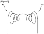
- the two coil structures (151, 152) may be provided in the Helmholtz type (see Figure 3 ), the dual pancake type (see Figure 4 ), or the bi-conical type (see Figure 5 ).
- the magnetic particles may comprise metal particles, metal oxides, ferrite, or alloy particles, having ferromagnetism.
- the magnetic particles may comprise magnetic nanoparticles.
- the ink composition (I) may comprise a thermosetting polymer and magnetic nanoparticles.
- a magnetic field is formed in the magnetic nanoparticles, whereby the thermosetting polymer can be cured by the generated heat. Therefore, the ink composition (I) can also be cured only by applying an external alternating electromagnetic field instead of curing by the direct heat.
- the kind of monomers or oligomers in the thermosetting polymer is not particularly limited, but one or more selected from the group consisting of a monomer of an epoxy resin, a monomer of a phenol resin, a monomer of an amino resin, a monomer of an unsaturated polyester resin, a monomer of an acrylic resin, a monomer of a maleimide resin and a monomer of a cyanate resin can be used, and preferably one or more selected from the group consisting of a monomer of an epoxy resin, a monomer of an acrylic resin and a monomer of a maleimide resin can be used.
- the monomer or oligomer of the thermosetting polymer may also be contained in an amount of 80 to 99 parts by weight, relative to the total weight of the ink composition.
- the magnetic nanoparticles have a diameter of 1 to 999 nm, preferably a diameter of 30 to 300 nm, more preferably a diameter of 50 to 100 nm, and still more preferably a diameter of 50 to 60 nm.
- the magnetic nanoparticles may be one or more selected from the group consisting of Fe 3 O 4 , Fe 2 O 3 , MnFe 2 O 4 , CoFe 2 O 4 , Fe, CoPt, and FePt.
- the ink composition (I) may comprise 80 to 99 parts by weight of the thermosetting polymer and 1 to 20 parts by weight of the magnetic nanoparticles, relative to the total weight. If the content of the magnetic nanoparticles is less than 1 part by weight, the time for curing the ink composition becomes longer, and if the content of the magnetic nanoparticles exceeds 20 parts by weight, the color of the cured resin may become much darker due to blackish magnetic nanoparticles. Also, as an aggregation phenomenon of the magnetic nanoparticles may occur, voids in the cured resin may also be caused, whereby cracking may also be caused.
- the ink composition may further comprise one or more selected from the group consisting of a curing agent and a cross-linking agent.
- a curing agent is not particularly limited, but for example, one or more selected from the group consisting of organic peroxides, hydroperoxides, azo compounds, imidazoles, aliphatic amines, aromatic amines, tertiary amines, polyamide resins, phenol resins and acid anhydrides can be used.
- the curing agent may be included in an amount of 1 to 10 parts by weight, and preferably 1 to 5 parts by weight, relative to the total weight of the ink composition.
- the content of the curing agent is less than 1 part by weight, it may take a long time to completely cure the ink composition, and if it is more than 10 parts by weight, a large amount of polymer having a short chain length may be generated to reduce thermal stability of the cured resin.
- the kind of the cross-linking agent is not particularly limited, but for example, one or more selected from the group consisting of phenol novolac resins, phenol alkyl resins, allylated phenol novolac resins and microcapsule type cross-linking agent can be used.
- the cross-linking agent By further using the cross-linking agent, hardness and thermal stability of the ink composition can be increased.
- the cross-linking agent may be included in an amount of 1 to 10 parts by weight, relative to the total weight of the ink composition, where if the content of the cross-linking agent is less than 1 part by weight, cross-linking is not sufficiently carried out and thus the polymer may be melted at a high temperature and flow, and expansion due to the solvent may occur, and if it is more than 10 parts by weight, cross-linking is excessively large and thus the cured resin may be in a fragile state.
- the injection nozzle (40) connected to the ink tank (10) and the heating unit (50) for applying an external alternating electromagnetic field to the ink composition so as to form thermal curing can constitute the printer head (30).
- the above-described carriage unit (60) adjusts the relative position of the printer head (30) with respect to the substrate (20).
- control unit (70) is provided to control the carriage unit (60) and the print head (30). Also, the control unit (70) can control to form the injection of the ink composition (I) and the generation of the external alternating electromagnetic field simultaneously.
- the carriage unit (60) may be configured as a conventional carriage unit for carrying the nozzle head from the printer.
- the carriage unit (60) may comprise a rail part according to the injection trajectory and one or more motors for moving the printer head (30) on the rail part.
- the carriage unit (60) may comprise one or more motors (e.g., step motors) for raising and lowering the printer head (30) and/or the substrate (20).
- the ink composition related to the present invention may comprise micro-sized metal particles and additives (for example, organic components).
- the metal particles are thermally fused through induction heating, so that the 3D printing may proceed.
- the ink composition may also comprise a thermosetting resin and magnetic nanoparticles (thermosetting resin ink), or may also comprise metal particles and additives (metallic ink).
- thermosetting resin ink the thermosetting polymer is included as the main component, based on the total weight of the ink composition, and the magnetic nanoparticles are included as the auxiliary component, whereas in the case of the metallic ink, micro-sized metal particles are included as the main component.
- the metallic ink it is possible to remove additive components through the process of thermally fusing metal particles via induction heating.
- the magnetic particles may comprise metal oxide, ferrite or alloy particles.
- the metal oxide may also comprise one or more oxides selected from the group consisting of iron (Fe), cobalt (Co), nickel (Ni), chromium (Cr), yttrium (Y), samarium (Sm) and gadolinium (Gd).
- the ferrite comprises MO ⁇ Fe 2 O 3 , where M may be a divalent metal ion.
- the divalent metal ion may comprise manganese, iron, cobalt, nickel or zinc.
- the alloy particles may comprise FePt, CoPt, Ni-Zn or Mn-Zn.
- the ink may comprise ceramic particles.
- the ceramic may comprise one or more oxides, nitrides, or carbides selected from the group consisting of silicon (Si), aluminum (Al), titanium (Ti) and zirconium (Zr).
- the ink may comprise inorganic particles and ceramic particles, having a core-shell structure.
- the shell may comprise ceramic.
- the core may comprise magnetic particles or a metal powder and the core may comprise one or more oxides selected from the group consisting of iron (Fe), cobalt (Co), nickel (Ni), chromium (Cr), yttrium (Y), samarium (Sm) and gadolinium (Gd).
- the composition may comprise a ceramic sol solvent.
- the composition may be a ceramic sol solution.
- the uniform thermal curing can be performed by generating heat from the magnetic particles or the metal powder uniformly dispersed in the composition, and the strength of the finally cured product can be increased by accompanying the curing of the ceramic particles together with the curing of the ceramic sol.
- the curing may be performed by sintering between the ceramic materials, without being limited thereto, and the curing of the composition may proceed with the curable resin as described below.
- the 3D printer related to the present invention is capable of generating thermal curing or thermal fusion of an ink (or ink composition) through induction heating and is provided so as to be capable of forming a focused alternating electromagnetic field in a region on which the ink is applied.
Landscapes
- Chemical & Material Sciences (AREA)
- Engineering & Computer Science (AREA)
- Materials Engineering (AREA)
- Manufacturing & Machinery (AREA)
- Physics & Mathematics (AREA)
- Mechanical Engineering (AREA)
- Optics & Photonics (AREA)
- Ceramic Engineering (AREA)
- Civil Engineering (AREA)
- Composite Materials (AREA)
- Structural Engineering (AREA)
Description
- The present invention relates to a 3D printer.
- This application claims the benefit of priority based on
Korean Patent Application No. 10-2015-0063861 filed on May 7, 2015 Korean Patent Application No. 10-2016-0056080 filed on May 9, 2016 - A 3D printer is a printer that outputs objects three-dimensionally and has various printing methods depending on materials of inks.
- As the 3D printing method, for example, a method of melting and extruding an ink through a heated print head using a thermoplastic polymer fiber as the ink, or a method of photo-curing an ink through a laser using a photo-curable resin as the ink has been used. However, when the thermoplastic polymer fiber is used as the ink, there is a disadvantage that the resolution is low, and when the photo-curable resin is used as the ink, the resolution is high, but since the optical equipment must be used, there is a disadvantage that the volume of the apparatus becomes large.
- In addition, there is a problem that 3D inks are produced in accordance with each printing method, so that there is little interchangeability.
-
US 2010/0171792 A1 describes method in which a direct write ink is applied onto a region of a substrate, and an inductive heating arrangement is positioned adjacent to said region and supplied with an electrical current to heat said region by electromagnetic inductive effects, thereby fixing the direct write ink. - It is an object to be solved by the present invention to provide a 3D printer capable of inducing thermal curing or thermal fusion of inks through induction heating.
- Also, it is another object to be solved by the present invention to provide a 3D printer comprising one or more coil structures positioned behind an injection nozzle and provided so as to be capable of forming a focused alternating electromagnetic field in a region on which the ink is applied.
- Also, it is another object to be solved by the present invention to provide a 3D printer capable of adjusting at least one of an interval between an injection nozzle and a substrate and an interval between a heating unit and the substrate, and continuously performing 3D printing.
- To solve the above-described objects, according to one aspect of the present invention, there is provided a 3D printer comprising an ink tank for storing an ink comprising magnetic particles, an injection nozzle connected to the ink tank and for injecting the ink, a substrate on which the injected ink is deposited, a heating unit provided so as to heat the ink coated onto the substrate by means of induction heating and to be positioned behind the injection nozzle based on the direction of carriage of the injection nozzle, a carriage unit for carrying the injection nozzle and the heating unit, and a control unit for controlling the heating unit and the carriage unit.
- In addition, the heating unit is provided to apply an external alternating electromagnetic field to the ink deposited on the substrate.
- Furthermore, the heating unit may be provided to form a focused alternating electromagnetic field on the ink deposited on the substrate.
- Also, the heating unit comprises two coil structures.
- Also, the coil structure may have a cylindrical shape (solenoid), a spiral shape, or a pancake shape.
- Also, the coil structure may have a circular or rectangular coil shape.
- Also, the heating unit comprises two coil structures disposed on both sides of the rear, respectively, based on the injection nozzle. At this time, the heating unit is provided to apply the external alternating electromagnetic field to the ink positioned in the space between the two coil structures.
- Also, the heating unit may be disposed to be located at the same height as the injection nozzle, and the heating unit may be disposed to be located at a height different from the injection nozzle. For example, the heating unit may be disposed so as to be located about 1 mm below the injection nozzle.
- Also, the heating unit may be provided so that the center line of the nozzle head in the injection nozzle is located between the two coil structures. In particular, the heating unit may be provided such that the two coil structures are symmetrically arranged along the center line of the nozzle head in the injection nozzle.
- Also, the nozzle head of the injection nozzle may have a diameter of 100 µm or less, and preferably 10 to 50 µm.
- Also, the two coil structures may be provided in a Helmholtz type, a bi-conical type, or a dual pancake type.
- Also, the carriage unit may be provided to carry the heating unit and the injection nozzle integrally.
- Also, the carriage unit may be provided to carry the heating unit and the injection nozzle individually.
- Also, the carriage unit may be provided to carry the heating unit and the injection nozzle at speeds different from each other.
- Also, the carriage unit may be provided to adjust the relative position of the heating unit with respect to the substrate.
- Also, at least one of the heating unit and the substrate may be provided so as to be movable up and down. For example, the heating unit may be provided so as to be movable up and down with respect to the substrate.
- Also, the carriage unit may be provided to adjust the interval between the substrate and the injection nozzle. For example, the injection nozzle may be provided so as to be movable up and down with respect to the substrate.
- Also, the control unit may be provided to operate the heating unit while applying the ink. Alternatively, the control unit may be provided to operate the heating unit after a predetermined time has elapsed from the application of the ink.
- Also, the magnetic particles may comprise metal particles, metal oxides, or alloy particles, having magnetism.
- Also, the ink may comprise single molecules, oligomers, or polymers, including a thermosetting group. For example, the ink may comprise a thermosetting polymer.
- Also, the ink may comprise ceramic particles, where the ceramic particles may comprise one or more oxides, nitrides, or carbides selected from the group consisting of silicon (Si), aluminum (Al), titanium (Ti), and zirconium (Zr).
- As described above, the 3D printer related to at least one embodiment of the present invention has the following effects.
- The 3D printer is capable of generating thermal curing or thermal fusion of an ink (or ink composition) through induction heating and is provided so as to be capable of forming a focused alternating electromagnetic field in a region on which the ink is applied.
- In addition, the 3D printer is provided so that the interval between at least one of an interval between the injection nozzle and the substrate and an interval between the heating unit and the substrate is adjustable, and capable of continuously 3D printing.
-
-
Figure 1 is a configuration diagram showing a 3D printer related to one embodiment of the present invention. -
Figures 2 to 5 are conceptual diagrams showing various embodiments of the heating unit related to the present invention. - Hereinafter, a 3D printer according to one embodiment of the present invention will be described in detail with reference to the accompanying drawings.
- In addition, the same or similar reference numerals are given to the same or corresponding components regardless of reference numerals, of which redundant explanations will be omitted, and for convenience of explanation, the size and shape of each constituent member as shown may be exaggerated or reduced.
-
Figure 1 is a configuration diagram showing a 3D printer related to one embodiment of the present invention, andFigures 2 to 5 are conceptual diagrams showing various embodiments of the heating unit related to the present invention. - The ink may mean hereby an ink composition that can be thermally fused or thermally cured by induction heating, and the term such as ink or ink composition may be used together in the same sense.
- Referring to
Figure 1 , the 3D printer (1) related to one embodiment of the present invention comprises an ink tank (10) in which an ink (I) containing magnetic particles is stored and an injection nozzle (40) connected to the ink tank (10) and for injecting the ink. The 3D printer (1) also comprises a substrate (20) on which the injected ink is deposited and a heating unit (50) provided so as to heat the ink coated onto the substrate (20) through induction heating and to be positioned behind the injection nozzle (40) based on the direction of carriage of the injection nozzle (40). The 3D printer (1) also comprises a carriage unit (60) for carrying the injection nozzle (40) and the heating unit (50). The 3D printer (1) also comprises a control unit (70) for controlling the heating unit (50) and the carriage unit (50). - In addition, the heating unit (50) is provided to apply an external alternating electromagnetic field to the ink composition (C) deposited on the substrate (20). Specifically, the ink composition (C) can be heated while the induction heating is generated by the electromagnetic field.
- Here, as described below, in the ink composition (C), the thermosetting resin can be cured or the metal particles can be thermally fused, depending on the composition, whereby the three-dimensional printing can proceed. Referring to
Figure 1 , for convenience of explanation, the ink injected from the injection nozzle (40) is indicated by the letter I and the ink heated through the heating unit (50) is indicated by the letter C. - Also, the external alternating electromagnetic field may have a frequency of 100 kHz to 1 GHz and a current of 5 A to 500 A. When the frequency and the current are applied within the above range, the ink composition can be completely cured within about 10 seconds to 1 hour.
- Referring to
Figure 1 , the heating unit (50) may be provided to form a focused alternating electromagnetic field on the ink composition (C) deposited on the substrate (20). In addition, the heating unit (50) comprises two coil structures. Here, the coil structure may have various structures such as a circular shape, a polygonal shape, and a spiral shape. Furthermore, the coil structure can be used for surface heating, inner surface heating, flat plate heating, and the like. Also, the shape and number of the coil structure, and the arrangement between the coil structures can be variously determined. For example, the coil structure may have a cylindrical shape, a spiral shape, or a pancake shape. Also, the coil structure may have a circular or rectangular coil shape. - In addition, the heating unit (50) may be disposed adjacent to the injection nozzle (40). The heating unit (50) is also provided to be positioned behind the injection nozzle (40), based on the direction of carriage of the injection nozzle (40). Specifically, as the heating unit (50) is provided at the rear of the direction of carriage of the injection nozzle (40), the injection of the ink through the injection nozzle (40) and the heating of the ink through the heating unit (50) can be performed simultaneously or sequentially.
- In the above arrangement, the carriage unit (60) may be provided to carry the heating unit (50) and the injection nozzle (40) integrally. At this time, the heating unit (50) and the injection nozzle (40) can be carried at the same speed. Alternatively, the carriage unit (60) may be provided to carry the heating unit (50) and the injection nozzle (40) individually. At this time, the heating unit (50) and the injection nozzle (40) may be provided to be carried at speeds different from each other. The carriage unit may comprise a driving source such as a motor and may be constituted by a known element used for carrying the ink nozzle in the printer technology field.
- Meanwhile, the carriage unit (60) may be provided to adjust the interval between the substrate (20) and the heating unit (50). For example, the heating unit (50) may be provided so as to be movable up and down with respect to the substrate (20). Alternatively, the substrate (20) may be provided so as to be movable up and down with respect to the heating unit (50). That is, the carriage unit (60) may be provided to adjust the relative position of the heating unit (50) with respect to the substrate (20), and at least one of the heating unit (50) and the substrate (20) may be provided to be movable up and down. In addition, the carriage unit (60) may be provided to adjust the interval between the substrate (20) and the injection nozzle (40).
- Furthermore, the control unit (70) may be provided to operate the heating unit (50) while applying the ink (I). Alternatively, the control unit (70) may be provided to operate the heating unit (50) after a predetermined time has elapsed from the application of the ink.
- Referring to
Figure 2 , the heating unit (150) may comprise two coil structures (151, 152) disposed on both sides of the rear, respectively, base on the injection nozzle (40). In addition, the heating unit (150) may be provided to apply an external alternating electromagnetic field to the ink positioned in the space between the two coil structures (151, 152). The heating unit (150) may also be provided so that the center line (L) of the nozzle head in the injection nozzle (40) is located between the two coil structures (151, 152). For example, the two coil structures (151, 152) may be provided in the Helmholtz type (seeFigure 3 ), the dual pancake type (seeFigure 4 ), or the bi-conical type (seeFigure 5 ). - Hereinafter, the ink (ink composition) as described hereby will be specifically described.
- The magnetic particles may comprise metal particles, metal oxides, ferrite, or alloy particles, having ferromagnetism.
- In addition, the magnetic particles may comprise magnetic nanoparticles.
- For example, the ink composition (I) may comprise a thermosetting polymer and magnetic nanoparticles. By applying an external alternating electromagnetic field to the ink composition (I), a magnetic field is formed in the magnetic nanoparticles, whereby the thermosetting polymer can be cured by the generated heat. Therefore, the ink composition (I) can also be cured only by applying an external alternating electromagnetic field instead of curing by the direct heat.
- Furthermore, the kind of monomers or oligomers in the thermosetting polymer is not particularly limited, but one or more selected from the group consisting of a monomer of an epoxy resin, a monomer of a phenol resin, a monomer of an amino resin, a monomer of an unsaturated polyester resin, a monomer of an acrylic resin, a monomer of a maleimide resin and a monomer of a cyanate resin can be used, and preferably one or more selected from the group consisting of a monomer of an epoxy resin, a monomer of an acrylic resin and a monomer of a maleimide resin can be used.
- The monomer or oligomer of the thermosetting polymer may also be contained in an amount of 80 to 99 parts by weight, relative to the total weight of the ink composition.
- On the other hand, the magnetic nanoparticles have a diameter of 1 to 999 nm, preferably a diameter of 30 to 300 nm, more preferably a diameter of 50 to 100 nm, and still more preferably a diameter of 50 to 60 nm. Here, if the diameter of the magnetic nanoparticles exceeds the nano size, the ink composition may not be able to ensure dispersibility. In addition, the magnetic nanoparticles may be one or more selected from the group consisting of Fe3O4, Fe2O3, MnFe2O4, CoFe2O4, Fe, CoPt, and FePt.
- In addition, the ink composition (I) may comprise 80 to 99 parts by weight of the thermosetting polymer and 1 to 20 parts by weight of the magnetic nanoparticles, relative to the total weight. If the content of the magnetic nanoparticles is less than 1 part by weight, the time for curing the ink composition becomes longer, and if the content of the magnetic nanoparticles exceeds 20 parts by weight, the color of the cured resin may become much darker due to blackish magnetic nanoparticles. Also, as an aggregation phenomenon of the magnetic nanoparticles may occur, voids in the cured resin may also be caused, whereby cracking may also be caused.
- Furthermore, the ink composition may further comprise one or more selected from the group consisting of a curing agent and a cross-linking agent. The type of the curing agent is not particularly limited, but for example, one or more selected from the group consisting of organic peroxides, hydroperoxides, azo compounds, imidazoles, aliphatic amines, aromatic amines, tertiary amines, polyamide resins, phenol resins and acid anhydrides can be used. The curing agent may be included in an amount of 1 to 10 parts by weight, and preferably 1 to 5 parts by weight, relative to the total weight of the ink composition. If the content of the curing agent is less than 1 part by weight, it may take a long time to completely cure the ink composition, and if it is more than 10 parts by weight, a large amount of polymer having a short chain length may be generated to reduce thermal stability of the cured resin.
- Also, the kind of the cross-linking agent is not particularly limited, but for example, one or more selected from the group consisting of phenol novolac resins, phenol alkyl resins, allylated phenol novolac resins and microcapsule type cross-linking agent can be used. By further using the cross-linking agent, hardness and thermal stability of the ink composition can be increased. The cross-linking agent may be included in an amount of 1 to 10 parts by weight, relative to the total weight of the ink composition, where if the content of the cross-linking agent is less than 1 part by weight, cross-linking is not sufficiently carried out and thus the polymer may be melted at a high temperature and flow, and expansion due to the solvent may occur, and if it is more than 10 parts by weight, cross-linking is excessively large and thus the cured resin may be in a fragile state.
- Meanwhile, the injection nozzle (40) connected to the ink tank (10) and the heating unit (50) for applying an external alternating electromagnetic field to the ink composition so as to form thermal curing can constitute the printer head (30). At this time, the above-described carriage unit (60) adjusts the relative position of the printer head (30) with respect to the substrate (20).
- In addition, the control unit (70) is provided to control the carriage unit (60) and the print head (30). Also, the control unit (70) can control to form the injection of the ink composition (I) and the generation of the external alternating electromagnetic field simultaneously.
- The carriage unit (60) may be configured as a conventional carriage unit for carrying the nozzle head from the printer. For example, the carriage unit (60) may comprise a rail part according to the injection trajectory and one or more motors for moving the printer head (30) on the rail part. In addition, the carriage unit (60) may comprise one or more motors (e.g., step motors) for raising and lowering the printer head (30) and/or the substrate (20).
- In addition, the ink composition related to the present invention may comprise micro-sized metal particles and additives (for example, organic components). In this case, the metal particles are thermally fused through induction heating, so that the 3D printing may proceed. To summarize, the ink composition may also comprise a thermosetting resin and magnetic nanoparticles (thermosetting resin ink), or may also comprise metal particles and additives (metallic ink). In the case of the thermosetting resin ink, the thermosetting polymer is included as the main component, based on the total weight of the ink composition, and the magnetic nanoparticles are included as the auxiliary component, whereas in the case of the metallic ink, micro-sized metal particles are included as the main component. Particularly, in the case of the metallic ink, it is possible to remove additive components through the process of thermally fusing metal particles via induction heating.
- Furthermore, the magnetic particles may comprise metal oxide, ferrite or alloy particles. The metal oxide may also comprise one or more oxides selected from the group consisting of iron (Fe), cobalt (Co), nickel (Ni), chromium (Cr), yttrium (Y), samarium (Sm) and gadolinium (Gd). Also, the ferrite comprises MO·Fe2O3, where M may be a divalent metal ion. In addition, the divalent metal ion may comprise manganese, iron, cobalt, nickel or zinc. Also, the alloy particles may comprise FePt, CoPt, Ni-Zn or Mn-Zn.
- Also, the ink may comprise ceramic particles. Specifically, the ceramic may comprise one or more oxides, nitrides, or carbides selected from the group consisting of silicon (Si), aluminum (Al), titanium (Ti) and zirconium (Zr). In addition, the ink may comprise inorganic particles and ceramic particles, having a core-shell structure. At this time, the shell may comprise ceramic. Also, the core may comprise magnetic particles or a metal powder and the core may comprise one or more oxides selected from the group consisting of iron (Fe), cobalt (Co), nickel (Ni), chromium (Cr), yttrium (Y), samarium (Sm) and gadolinium (Gd).
- In addition, the composition may comprise a ceramic sol solvent. Accordingly, the composition may be a ceramic sol solution. In this case, the uniform thermal curing can be performed by generating heat from the magnetic particles or the metal powder uniformly dispersed in the composition, and the strength of the finally cured product can be increased by accompanying the curing of the ceramic particles together with the curing of the ceramic sol. The curing may be performed by sintering between the ceramic materials, without being limited thereto, and the curing of the composition may proceed with the curable resin as described below.
- The preferred embodiments of the present invention as described above are disclosed for illustrative purposes, which can be modified, changed and added within thought and scope of the present invention by those skilled in the art and it will be considered that such modification, change and addition fall within the following claims.
- The 3D printer related to the present invention is capable of generating thermal curing or thermal fusion of an ink (or ink composition) through induction heating and is provided so as to be capable of forming a focused alternating electromagnetic field in a region on which the ink is applied.
Claims (13)
- A 3D printer (1) comprising an ink tank (10) for storing an ink (I) comprising magnetic particles; an injection nozzle (40) connected to the ink tank (10) and for injecting the ink (I);
a substrate (20) on which the injected ink (I) is deposited;
a heating unit (50) provided so as to heat the ink (I) coated onto the substrate (20) by means of induction heating and to be positioned behind the injection nozzle (40) based on the direction of carriage of the injection nozzle (40);
a carriage unit (60) for carrying the injection nozzle (40) and the heating unit (50); and
a control unit (70) for controlling the heating unit (50) and the carriage unit (60),
wherein the heating unit (50) comprises two coil structures (151, 152) disposed on both sides of the rear with respect to the injection nozzle (40), and
wherein the heating unit (50) is provided to apply an external alternating electromagnetic field to the ink (I) positioned in the space between the two coil structures (151, 152). - The 3D printer according to claim 1,
wherein the heating unit (50) is provided so as to apply an external alternating electromagnetic field to the ink (I) deposited on the substrate (20). - The 3D printer according to claim 2,
wherein the heating unit (50) is provided so as to form a focused alternating electromagnetic field on the ink (I) deposited on the substrate (20). - The 3D printer according to claim 1,
wherein the coil structure (151, 152) has a cylindrical shape, a spiral shape, or a pancake shape. - The 3D printer according to claim 1,
wherein the coil structure (151, 152) has a circular or rectangular coil shape. - The 3D printer according to claim 1,
wherein the heating unit (50) is provided so that the center line of the nozzle head in the injection nozzle (40) is located between the two coil structures (151,152). - The 3D printer according to claim 1,
wherein the two coil structures (151, 152) are provided in a Helmholtz type, a bi-conical type, or a dual pancake type. - The 3D printer according to any one of claims 1-7,
wherein the carriage unit (60) is provided to carry the heating unit (50) and the injection nozzle (40) integrally. - The 3D printer according to any one of claims 1-8,
wherein the carriage unit (60) is provided to carry the heating unit (50) and the injection nozzle (40) individually. - The 3D printer according to claim 9,
wherein the carriage unit (60) is provided to carry the heating unit (50) and the injection nozzle (40) at speeds different from each other. - The 3D printer according to any one of claims 1-10,
wherein the carriage unit (60) is provided to adjust the relative position of the heating unit (50) with respect to the substrate (20). - The 3D printer according to claim 11,
wherein at least one of the heating unit (50) and the substrate (20) is provided so as to be movable up and down. - The 3D printer according to any one of claims 1-12,
wherein the carriage unit (60) is provided to adjust the interval between the substrate (20) and the injection nozzle (40).
Applications Claiming Priority (2)
| Application Number | Priority Date | Filing Date | Title |
|---|---|---|---|
| KR20150063861 | 2015-05-07 | ||
| PCT/KR2016/004790 WO2016178545A1 (en) | 2015-05-07 | 2016-05-09 | 3d printer |
Publications (3)
| Publication Number | Publication Date |
|---|---|
| EP3292990A1 EP3292990A1 (en) | 2018-03-14 |
| EP3292990A4 EP3292990A4 (en) | 2019-03-27 |
| EP3292990B1 true EP3292990B1 (en) | 2021-08-11 |
Family
ID=57540601
Family Applications (1)
| Application Number | Title | Priority Date | Filing Date |
|---|---|---|---|
| EP16789651.3A Active EP3292990B1 (en) | 2015-05-07 | 2016-05-09 | 3d printer |
Country Status (5)
| Country | Link |
|---|---|
| US (1) | US10974455B2 (en) |
| EP (1) | EP3292990B1 (en) |
| JP (1) | JP6554740B2 (en) |
| KR (1) | KR101819335B1 (en) |
| CN (1) | CN107614244B (en) |
Families Citing this family (17)
| Publication number | Priority date | Publication date | Assignee | Title |
|---|---|---|---|---|
| JP6641464B2 (en) | 2015-09-25 | 2020-02-05 | エルジー・ケム・リミテッド | Composition for 3D printing |
| EP3354684B1 (en) * | 2015-09-25 | 2021-11-17 | LG Chem, Ltd. | Composition for 3d printing |
| US11872623B2 (en) | 2016-11-04 | 2024-01-16 | Lg Chem, Ltd. | Thermosetting composition |
| KR102089406B1 (en) * | 2017-04-26 | 2020-03-16 | 주식회사 엘지화학 | Nozzle assembly comprising the same and 3-D printer comprising the same |
| KR102171282B1 (en) * | 2017-04-26 | 2020-10-28 | 주식회사 엘지화학 | Nozzle assembly comprising the same and 3-D printer comprising the same |
| KR102524712B1 (en) * | 2017-04-28 | 2023-04-25 | 3디 글래스 솔루션즈 인코포레이티드 | Rf circulator |
| KR102152465B1 (en) * | 2018-10-10 | 2020-09-07 | 한국기계연구원 | Apparatus and method for powder control of 3D printing system |
| CN109333999B (en) * | 2018-11-20 | 2023-12-29 | 青岛科技大学 | Thermosetting polymer additive manufacturing device and method |
| JP7204276B2 (en) | 2018-12-06 | 2023-01-16 | エルジー・ケム・リミテッド | DISCHARGED APPARATUS, FORMING APPARATUS, AND METHOD FOR MANUFACTURING MOLDED BODY |
| CN109483869B (en) * | 2018-12-12 | 2020-10-20 | 哈尔滨工业大学 | Device for on-orbit 4D printing of thermosetting shape memory polymer |
| JP7321624B2 (en) * | 2018-12-25 | 2023-08-07 | エルジー・ケム・リミテッド | Molding apparatus and molded product manufacturing method |
| US20220289935A1 (en) * | 2019-07-11 | 2022-09-15 | Lg Chem, Ltd. | Resin-Filled Material, and the Manufacturing Method Thereof |
| JP7367358B2 (en) * | 2019-07-11 | 2023-10-24 | 大同特殊鋼株式会社 | Bonded magnet manufacturing method |
| EP3875185A1 (en) * | 2020-03-05 | 2021-09-08 | Evonik Operations GmbH | Selective superparamagnetic sintering and corresponding ink |
| KR102215528B1 (en) | 2020-04-16 | 2021-02-16 | 주식회사 웨이브피아 | Nozzle structure using RF heating device for 3D printer |
| EP4094926B1 (en) * | 2021-05-26 | 2024-01-31 | uppolluX GmbH & Co. KG | Device, system and use of same and method for producing a 3d structure |
| KR102570503B1 (en) * | 2021-08-09 | 2023-08-24 | 한양대학교 산학협력단 | Metal 3d printer with vibrating part and heating part |
Family Cites Families (12)
| Publication number | Priority date | Publication date | Assignee | Title |
|---|---|---|---|---|
| JP2000094530A (en) * | 1998-09-25 | 2000-04-04 | Canon Inc | Apparatus and method for shaping |
| US6405095B1 (en) * | 1999-05-25 | 2002-06-11 | Nanotek Instruments, Inc. | Rapid prototyping and tooling system |
| US20040151978A1 (en) * | 2003-01-30 | 2004-08-05 | Huang Wen C. | Method and apparatus for direct-write of functional materials with a controlled orientation |
| US8437104B2 (en) * | 2006-04-06 | 2013-05-07 | Sigma Pro Ltd. Llc | Read/write apparatus and method for a magnetic storage medium comprised of magnetic nanoparticles contained within nanotubes |
| WO2007114895A2 (en) | 2006-04-06 | 2007-10-11 | Z Corporation | Production of three-dimensional objects by use of electromagnetic radiation |
| US8177348B2 (en) * | 2007-06-01 | 2012-05-15 | Bae Systems Plc | Direct write and additive manufacturing processes |
| EP2182787A1 (en) | 2008-10-30 | 2010-05-05 | BAE Systems PLC | Improvements relating to additive manufacturing processes |
| JP2013067036A (en) | 2011-09-21 | 2013-04-18 | Keyence Corp | Three-dimensional shaping apparatus |
| EP2764934B1 (en) * | 2013-02-11 | 2015-06-17 | King Abdulaziz City for Science & Technology (KACST) | Method for manufacturing an element of a plurality of casting mold elements and casting method for manufacturing and system for casting a 3-dimensional object |
| US20140363326A1 (en) * | 2013-06-10 | 2014-12-11 | Grid Logic Incorporated | System and method for additive manufacturing |
| JP2015000476A (en) | 2013-06-13 | 2015-01-05 | コニカミノルタ株式会社 | Three-dimensional molding method and three-dimensional molding device |
| EP2868692B1 (en) * | 2013-11-05 | 2017-10-25 | DSM IP Assets B.V. | Stabilized matrix-filled liquid radiation curable resin compositions for additive fabrication |
-
2016
- 2016-05-09 EP EP16789651.3A patent/EP3292990B1/en active Active
- 2016-05-09 CN CN201680025954.5A patent/CN107614244B/en active Active
- 2016-05-09 JP JP2017554556A patent/JP6554740B2/en active Active
- 2016-05-09 KR KR1020160056080A patent/KR101819335B1/en active IP Right Grant
- 2016-05-09 US US15/569,942 patent/US10974455B2/en active Active
Also Published As
| Publication number | Publication date |
|---|---|
| US10974455B2 (en) | 2021-04-13 |
| EP3292990A1 (en) | 2018-03-14 |
| JP6554740B2 (en) | 2019-08-07 |
| EP3292990A4 (en) | 2019-03-27 |
| US20180154577A1 (en) | 2018-06-07 |
| JP2018515361A (en) | 2018-06-14 |
| KR20160131954A (en) | 2016-11-16 |
| KR101819335B1 (en) | 2018-01-17 |
| CN107614244B (en) | 2020-01-17 |
| CN107614244A (en) | 2018-01-19 |
Similar Documents
| Publication | Publication Date | Title |
|---|---|---|
| EP3292990B1 (en) | 3d printer | |
| WO2016178545A1 (en) | 3d printer | |
| KR102126705B1 (en) | Composition | |
| US10124531B2 (en) | Rapid non-contact energy transfer for additive manufacturing driven high intensity electromagnetic fields | |
| EP3354376B1 (en) | Composition for 3d printing | |
| Shen et al. | UV-assisted direct write of polymer-bonded magnets | |
| US20150183164A1 (en) | Rapid electro-magnetic heating of nozzle in polymer extrusion based deposition for additive manufacturing | |
| JP2013063641A (en) | Method, apparatus and material mixture for direct digital manufacturing of fiber reinforced part | |
| US20130309488A1 (en) | Resin molded body and method of manufacturing same | |
| KR102041811B1 (en) | Composition for 3 dimensional printing | |
| US20210280368A1 (en) | Method for three-dimensional printing of magnetic materials | |
| US20180243826A1 (en) | Three-dimensional modeled-object manufacturing composition and three-dimensional modeled-object manufacturing method | |
| EP3711949A1 (en) | Method and apparatus for manufacturing a magnetic structure | |
| JP2016189462A (en) | Manufacturing method and manufacturing apparatus of anisotropic bonded magnet and anisotropic bonded magnet | |
| US20220388241A1 (en) | Use of Multi-Axis Magnetic fields in Orienting Material Property Enhancing Fibers, including for Strengthening and Joining purposes, in Additive Manufacturing Processes | |
| KR102041812B1 (en) | Thermosetting composition | |
| JP2017075369A (en) | Method for manufacturing three-dimensional molded article and apparatus for manufacturing three-dimensional molded article | |
| Sukhotskiy | Computational Analysis of Liquid Metal Drop-on-Demand Jetting and Solidification Using a Contactless Magnetohydrodynamic Actuator | |
| JP5114126B2 (en) | Magnetic seal member and manufacturing method thereof | |
| KR20230080905A (en) | Nozzle assembly, three-dimensional printer and three-dimensional printing method including the same, and electronic component case manufactured using the same | |
| CN113665099A (en) | Method for producing a component by means of a fuse and device for producing a component | |
| JP2017106082A (en) | Method for manufacturing three-dimensional molded object, apparatus for manufacturing three-dimensional molded object and three-dimensional molded object | |
| US20180243825A1 (en) | Three-dimensional modeled-object manufacturing composition and three-dimensional modeled-object manufacturing method |
Legal Events
| Date | Code | Title | Description |
|---|---|---|---|
| STAA | Information on the status of an ep patent application or granted ep patent |
Free format text: STATUS: THE INTERNATIONAL PUBLICATION HAS BEEN MADE |
|
| PUAI | Public reference made under article 153(3) epc to a published international application that has entered the european phase |
Free format text: ORIGINAL CODE: 0009012 |
|
| STAA | Information on the status of an ep patent application or granted ep patent |
Free format text: STATUS: REQUEST FOR EXAMINATION WAS MADE |
|
| 17P | Request for examination filed |
Effective date: 20171102 |
|
| AK | Designated contracting states |
Kind code of ref document: A1 Designated state(s): AL AT BE BG CH CY CZ DE DK EE ES FI FR GB GR HR HU IE IS IT LI LT LU LV MC MK MT NL NO PL PT RO RS SE SI SK SM TR |
|
| AX | Request for extension of the european patent |
Extension state: BA ME |
|
| DAV | Request for validation of the european patent (deleted) | ||
| DAX | Request for extension of the european patent (deleted) | ||
| A4 | Supplementary search report drawn up and despatched |
Effective date: 20190221 |
|
| RIC1 | Information provided on ipc code assigned before grant |
Ipc: B33Y 30/00 20150101ALI20190215BHEP Ipc: B29K 505/00 20060101ALN20190215BHEP Ipc: B29C 64/393 20170101ALI20190215BHEP Ipc: B29C 64/112 20170101ALI20190215BHEP Ipc: B29C 64/295 20170101AFI20190215BHEP Ipc: B29K 509/02 20060101ALN20190215BHEP Ipc: B33Y 50/02 20150101ALI20190215BHEP Ipc: B33Y 70/00 20150101ALI20190215BHEP Ipc: B33Y 40/00 20150101ALI20190215BHEP |
|
| RIC1 | Information provided on ipc code assigned before grant |
Ipc: B33Y 30/00 20150101ALI20210303BHEP Ipc: B33Y 50/02 20150101ALI20210303BHEP Ipc: B33Y 70/00 20200101ALI20210303BHEP Ipc: B29C 64/393 20170101ALI20210303BHEP Ipc: B29C 64/112 20170101ALI20210303BHEP Ipc: B33Y 40/00 20200101ALI20210303BHEP Ipc: B29C 64/295 20170101AFI20210303BHEP Ipc: B29K 505/00 20060101ALN20210303BHEP Ipc: B29K 509/02 20060101ALN20210303BHEP |
|
| REG | Reference to a national code |
Ref country code: DE Ref legal event code: R079 Ref document number: 602016062075 Country of ref document: DE Free format text: PREVIOUS MAIN CLASS: B29C0067000000 Ipc: B29C0064295000 |
|
| RIC1 | Information provided on ipc code assigned before grant |
Ipc: B29K 509/02 20060101ALN20210309BHEP Ipc: B29K 505/00 20060101ALN20210309BHEP Ipc: B29C 64/393 20170101ALI20210309BHEP Ipc: B33Y 50/02 20150101ALI20210309BHEP Ipc: B33Y 40/00 20200101ALI20210309BHEP Ipc: B33Y 30/00 20150101ALI20210309BHEP Ipc: B33Y 70/00 20200101ALI20210309BHEP Ipc: B29C 64/112 20170101ALI20210309BHEP Ipc: B29C 64/295 20170101AFI20210309BHEP |
|
| GRAP | Despatch of communication of intention to grant a patent |
Free format text: ORIGINAL CODE: EPIDOSNIGR1 |
|
| STAA | Information on the status of an ep patent application or granted ep patent |
Free format text: STATUS: GRANT OF PATENT IS INTENDED |
|
| RIC1 | Information provided on ipc code assigned before grant |
Ipc: B29C 35/08 20060101ALN20210401BHEP Ipc: B29K 509/02 20060101ALN20210401BHEP Ipc: B29K 505/00 20060101ALN20210401BHEP Ipc: B29C 64/393 20170101ALI20210401BHEP Ipc: B33Y 50/02 20150101ALI20210401BHEP Ipc: B33Y 40/00 20200101ALI20210401BHEP Ipc: B33Y 30/00 20150101ALI20210401BHEP Ipc: B33Y 70/00 20200101ALI20210401BHEP Ipc: B29C 64/112 20170101ALI20210401BHEP Ipc: B29C 64/295 20170101AFI20210401BHEP |
|
| RIC1 | Information provided on ipc code assigned before grant |
Ipc: B29C 35/08 20060101ALN20210409BHEP Ipc: B29K 509/02 20060101ALN20210409BHEP Ipc: B29K 505/00 20060101ALN20210409BHEP Ipc: B29C 64/393 20170101ALI20210409BHEP Ipc: B33Y 50/02 20150101ALI20210409BHEP Ipc: B33Y 40/00 20200101ALI20210409BHEP Ipc: B33Y 30/00 20150101ALI20210409BHEP Ipc: B33Y 70/00 20200101ALI20210409BHEP Ipc: B29C 64/112 20170101ALI20210409BHEP Ipc: B29C 64/295 20170101AFI20210409BHEP |
|
| INTG | Intention to grant announced |
Effective date: 20210430 |
|
| GRAS | Grant fee paid |
Free format text: ORIGINAL CODE: EPIDOSNIGR3 |
|
| GRAA | (expected) grant |
Free format text: ORIGINAL CODE: 0009210 |
|
| STAA | Information on the status of an ep patent application or granted ep patent |
Free format text: STATUS: THE PATENT HAS BEEN GRANTED |
|
| AK | Designated contracting states |
Kind code of ref document: B1 Designated state(s): AL AT BE BG CH CY CZ DE DK EE ES FI FR GB GR HR HU IE IS IT LI LT LU LV MC MK MT NL NO PL PT RO RS SE SI SK SM TR |
|
| REG | Reference to a national code |
Ref country code: CH Ref legal event code: EP |
|
| REG | Reference to a national code |
Ref country code: DE Ref legal event code: R096 Ref document number: 602016062075 Country of ref document: DE |
|
| REG | Reference to a national code |
Ref country code: IE Ref legal event code: FG4D Ref country code: AT Ref legal event code: REF Ref document number: 1418945 Country of ref document: AT Kind code of ref document: T Effective date: 20210915 |
|
| REG | Reference to a national code |
Ref country code: LT Ref legal event code: MG9D |
|
| REG | Reference to a national code |
Ref country code: NL Ref legal event code: MP Effective date: 20210811 |
|
| REG | Reference to a national code |
Ref country code: AT Ref legal event code: MK05 Ref document number: 1418945 Country of ref document: AT Kind code of ref document: T Effective date: 20210811 |
|
| PG25 | Lapsed in a contracting state [announced via postgrant information from national office to epo] |
Ref country code: RS Free format text: LAPSE BECAUSE OF FAILURE TO SUBMIT A TRANSLATION OF THE DESCRIPTION OR TO PAY THE FEE WITHIN THE PRESCRIBED TIME-LIMIT Effective date: 20210811 Ref country code: SE Free format text: LAPSE BECAUSE OF FAILURE TO SUBMIT A TRANSLATION OF THE DESCRIPTION OR TO PAY THE FEE WITHIN THE PRESCRIBED TIME-LIMIT Effective date: 20210811 Ref country code: NO Free format text: LAPSE BECAUSE OF FAILURE TO SUBMIT A TRANSLATION OF THE DESCRIPTION OR TO PAY THE FEE WITHIN THE PRESCRIBED TIME-LIMIT Effective date: 20211111 Ref country code: PT Free format text: LAPSE BECAUSE OF FAILURE TO SUBMIT A TRANSLATION OF THE DESCRIPTION OR TO PAY THE FEE WITHIN THE PRESCRIBED TIME-LIMIT Effective date: 20211213 Ref country code: HR Free format text: LAPSE BECAUSE OF FAILURE TO SUBMIT A TRANSLATION OF THE DESCRIPTION OR TO PAY THE FEE WITHIN THE PRESCRIBED TIME-LIMIT Effective date: 20210811 Ref country code: ES Free format text: LAPSE BECAUSE OF FAILURE TO SUBMIT A TRANSLATION OF THE DESCRIPTION OR TO PAY THE FEE WITHIN THE PRESCRIBED TIME-LIMIT Effective date: 20210811 Ref country code: FI Free format text: LAPSE BECAUSE OF FAILURE TO SUBMIT A TRANSLATION OF THE DESCRIPTION OR TO PAY THE FEE WITHIN THE PRESCRIBED TIME-LIMIT Effective date: 20210811 Ref country code: LT Free format text: LAPSE BECAUSE OF FAILURE TO SUBMIT A TRANSLATION OF THE DESCRIPTION OR TO PAY THE FEE WITHIN THE PRESCRIBED TIME-LIMIT Effective date: 20210811 Ref country code: BG Free format text: LAPSE BECAUSE OF FAILURE TO SUBMIT A TRANSLATION OF THE DESCRIPTION OR TO PAY THE FEE WITHIN THE PRESCRIBED TIME-LIMIT Effective date: 20211111 Ref country code: AT Free format text: LAPSE BECAUSE OF FAILURE TO SUBMIT A TRANSLATION OF THE DESCRIPTION OR TO PAY THE FEE WITHIN THE PRESCRIBED TIME-LIMIT Effective date: 20210811 |
|
| PG25 | Lapsed in a contracting state [announced via postgrant information from national office to epo] |
Ref country code: PL Free format text: LAPSE BECAUSE OF FAILURE TO SUBMIT A TRANSLATION OF THE DESCRIPTION OR TO PAY THE FEE WITHIN THE PRESCRIBED TIME-LIMIT Effective date: 20210811 Ref country code: LV Free format text: LAPSE BECAUSE OF FAILURE TO SUBMIT A TRANSLATION OF THE DESCRIPTION OR TO PAY THE FEE WITHIN THE PRESCRIBED TIME-LIMIT Effective date: 20210811 Ref country code: GR Free format text: LAPSE BECAUSE OF FAILURE TO SUBMIT A TRANSLATION OF THE DESCRIPTION OR TO PAY THE FEE WITHIN THE PRESCRIBED TIME-LIMIT Effective date: 20211112 |
|
| PG25 | Lapsed in a contracting state [announced via postgrant information from national office to epo] |
Ref country code: NL Free format text: LAPSE BECAUSE OF FAILURE TO SUBMIT A TRANSLATION OF THE DESCRIPTION OR TO PAY THE FEE WITHIN THE PRESCRIBED TIME-LIMIT Effective date: 20210811 |
|
| PG25 | Lapsed in a contracting state [announced via postgrant information from national office to epo] |
Ref country code: DK Free format text: LAPSE BECAUSE OF FAILURE TO SUBMIT A TRANSLATION OF THE DESCRIPTION OR TO PAY THE FEE WITHIN THE PRESCRIBED TIME-LIMIT Effective date: 20210811 |
|
| REG | Reference to a national code |
Ref country code: DE Ref legal event code: R097 Ref document number: 602016062075 Country of ref document: DE |
|
| PG25 | Lapsed in a contracting state [announced via postgrant information from national office to epo] |
Ref country code: SM Free format text: LAPSE BECAUSE OF FAILURE TO SUBMIT A TRANSLATION OF THE DESCRIPTION OR TO PAY THE FEE WITHIN THE PRESCRIBED TIME-LIMIT Effective date: 20210811 Ref country code: SK Free format text: LAPSE BECAUSE OF FAILURE TO SUBMIT A TRANSLATION OF THE DESCRIPTION OR TO PAY THE FEE WITHIN THE PRESCRIBED TIME-LIMIT Effective date: 20210811 Ref country code: RO Free format text: LAPSE BECAUSE OF FAILURE TO SUBMIT A TRANSLATION OF THE DESCRIPTION OR TO PAY THE FEE WITHIN THE PRESCRIBED TIME-LIMIT Effective date: 20210811 Ref country code: EE Free format text: LAPSE BECAUSE OF FAILURE TO SUBMIT A TRANSLATION OF THE DESCRIPTION OR TO PAY THE FEE WITHIN THE PRESCRIBED TIME-LIMIT Effective date: 20210811 Ref country code: CZ Free format text: LAPSE BECAUSE OF FAILURE TO SUBMIT A TRANSLATION OF THE DESCRIPTION OR TO PAY THE FEE WITHIN THE PRESCRIBED TIME-LIMIT Effective date: 20210811 Ref country code: AL Free format text: LAPSE BECAUSE OF FAILURE TO SUBMIT A TRANSLATION OF THE DESCRIPTION OR TO PAY THE FEE WITHIN THE PRESCRIBED TIME-LIMIT Effective date: 20210811 |
|
| PLBE | No opposition filed within time limit |
Free format text: ORIGINAL CODE: 0009261 |
|
| STAA | Information on the status of an ep patent application or granted ep patent |
Free format text: STATUS: NO OPPOSITION FILED WITHIN TIME LIMIT |
|
| 26N | No opposition filed |
Effective date: 20220512 |
|
| PG25 | Lapsed in a contracting state [announced via postgrant information from national office to epo] |
Ref country code: IT Free format text: LAPSE BECAUSE OF FAILURE TO SUBMIT A TRANSLATION OF THE DESCRIPTION OR TO PAY THE FEE WITHIN THE PRESCRIBED TIME-LIMIT Effective date: 20210811 |
|
| PG25 | Lapsed in a contracting state [announced via postgrant information from national office to epo] |
Ref country code: SI Free format text: LAPSE BECAUSE OF FAILURE TO SUBMIT A TRANSLATION OF THE DESCRIPTION OR TO PAY THE FEE WITHIN THE PRESCRIBED TIME-LIMIT Effective date: 20210811 |
|
| REG | Reference to a national code |
Ref country code: CH Ref legal event code: PL |
|
| REG | Reference to a national code |
Ref country code: BE Ref legal event code: MM Effective date: 20220531 |
|
| PG25 | Lapsed in a contracting state [announced via postgrant information from national office to epo] |
Ref country code: MC Free format text: LAPSE BECAUSE OF FAILURE TO SUBMIT A TRANSLATION OF THE DESCRIPTION OR TO PAY THE FEE WITHIN THE PRESCRIBED TIME-LIMIT Effective date: 20210811 Ref country code: LU Free format text: LAPSE BECAUSE OF NON-PAYMENT OF DUE FEES Effective date: 20220509 Ref country code: LI Free format text: LAPSE BECAUSE OF NON-PAYMENT OF DUE FEES Effective date: 20220531 Ref country code: CH Free format text: LAPSE BECAUSE OF NON-PAYMENT OF DUE FEES Effective date: 20220531 |
|
| PG25 | Lapsed in a contracting state [announced via postgrant information from national office to epo] |
Ref country code: IE Free format text: LAPSE BECAUSE OF NON-PAYMENT OF DUE FEES Effective date: 20220509 |
|
| PG25 | Lapsed in a contracting state [announced via postgrant information from national office to epo] |
Ref country code: BE Free format text: LAPSE BECAUSE OF NON-PAYMENT OF DUE FEES Effective date: 20220531 |
|
| PG25 | Lapsed in a contracting state [announced via postgrant information from national office to epo] |
Ref country code: HU Free format text: LAPSE BECAUSE OF FAILURE TO SUBMIT A TRANSLATION OF THE DESCRIPTION OR TO PAY THE FEE WITHIN THE PRESCRIBED TIME-LIMIT; INVALID AB INITIO Effective date: 20160509 |
|
| PG25 | Lapsed in a contracting state [announced via postgrant information from national office to epo] |
Ref country code: MK Free format text: LAPSE BECAUSE OF FAILURE TO SUBMIT A TRANSLATION OF THE DESCRIPTION OR TO PAY THE FEE WITHIN THE PRESCRIBED TIME-LIMIT Effective date: 20210811 Ref country code: CY Free format text: LAPSE BECAUSE OF FAILURE TO SUBMIT A TRANSLATION OF THE DESCRIPTION OR TO PAY THE FEE WITHIN THE PRESCRIBED TIME-LIMIT Effective date: 20210811 |
|
| PGFP | Annual fee paid to national office [announced via postgrant information from national office to epo] |
Ref country code: GB Payment date: 20240422 Year of fee payment: 9 |
|
| PGFP | Annual fee paid to national office [announced via postgrant information from national office to epo] |
Ref country code: DE Payment date: 20240422 Year of fee payment: 9 |
|
| PGFP | Annual fee paid to national office [announced via postgrant information from national office to epo] |
Ref country code: FR Payment date: 20240423 Year of fee payment: 9 |