EP3292983B1 - Flüssigblasvorrichtung und flüssigsblasformverfahren - Google Patents
Flüssigblasvorrichtung und flüssigsblasformverfahren Download PDFInfo
- Publication number
- EP3292983B1 EP3292983B1 EP16786090.7A EP16786090A EP3292983B1 EP 3292983 B1 EP3292983 B1 EP 3292983B1 EP 16786090 A EP16786090 A EP 16786090A EP 3292983 B1 EP3292983 B1 EP 3292983B1
- Authority
- EP
- European Patent Office
- Prior art keywords
- preform
- blow molding
- support pin
- liquid
- liquid blow
- Prior art date
- Legal status (The legal status is an assumption and is not a legal conclusion. Google has not performed a legal analysis and makes no representation as to the accuracy of the status listed.)
- Active
Links
Images


Classifications
-
- B—PERFORMING OPERATIONS; TRANSPORTING
- B29—WORKING OF PLASTICS; WORKING OF SUBSTANCES IN A PLASTIC STATE IN GENERAL
- B29C—SHAPING OR JOINING OF PLASTICS; SHAPING OF MATERIAL IN A PLASTIC STATE, NOT OTHERWISE PROVIDED FOR; AFTER-TREATMENT OF THE SHAPED PRODUCTS, e.g. REPAIRING
- B29C49/00—Blow-moulding, i.e. blowing a preform or parison to a desired shape within a mould; Apparatus therefor
- B29C49/02—Combined blow-moulding and manufacture of the preform or the parison
- B29C49/06—Injection blow-moulding
-
- B—PERFORMING OPERATIONS; TRANSPORTING
- B29—WORKING OF PLASTICS; WORKING OF SUBSTANCES IN A PLASTIC STATE IN GENERAL
- B29C—SHAPING OR JOINING OF PLASTICS; SHAPING OF MATERIAL IN A PLASTIC STATE, NOT OTHERWISE PROVIDED FOR; AFTER-TREATMENT OF THE SHAPED PRODUCTS, e.g. REPAIRING
- B29C49/00—Blow-moulding, i.e. blowing a preform or parison to a desired shape within a mould; Apparatus therefor
- B29C49/08—Biaxial stretching during blow-moulding
- B29C49/10—Biaxial stretching during blow-moulding using mechanical means for prestretching
- B29C49/12—Stretching rods
-
- B—PERFORMING OPERATIONS; TRANSPORTING
- B29—WORKING OF PLASTICS; WORKING OF SUBSTANCES IN A PLASTIC STATE IN GENERAL
- B29C—SHAPING OR JOINING OF PLASTICS; SHAPING OF MATERIAL IN A PLASTIC STATE, NOT OTHERWISE PROVIDED FOR; AFTER-TREATMENT OF THE SHAPED PRODUCTS, e.g. REPAIRING
- B29C49/00—Blow-moulding, i.e. blowing a preform or parison to a desired shape within a mould; Apparatus therefor
- B29C49/28—Blow-moulding apparatus
-
- B—PERFORMING OPERATIONS; TRANSPORTING
- B29—WORKING OF PLASTICS; WORKING OF SUBSTANCES IN A PLASTIC STATE IN GENERAL
- B29C—SHAPING OR JOINING OF PLASTICS; SHAPING OF MATERIAL IN A PLASTIC STATE, NOT OTHERWISE PROVIDED FOR; AFTER-TREATMENT OF THE SHAPED PRODUCTS, e.g. REPAIRING
- B29C49/00—Blow-moulding, i.e. blowing a preform or parison to a desired shape within a mould; Apparatus therefor
- B29C49/42—Component parts, details or accessories; Auxiliary operations
- B29C49/4273—Auxiliary operations after the blow-moulding operation not otherwise provided for
- B29C49/42808—Filling the article
-
- B—PERFORMING OPERATIONS; TRANSPORTING
- B29—WORKING OF PLASTICS; WORKING OF SUBSTANCES IN A PLASTIC STATE IN GENERAL
- B29C—SHAPING OR JOINING OF PLASTICS; SHAPING OF MATERIAL IN A PLASTIC STATE, NOT OTHERWISE PROVIDED FOR; AFTER-TREATMENT OF THE SHAPED PRODUCTS, e.g. REPAIRING
- B29C49/00—Blow-moulding, i.e. blowing a preform or parison to a desired shape within a mould; Apparatus therefor
- B29C49/42—Component parts, details or accessories; Auxiliary operations
- B29C49/46—Component parts, details or accessories; Auxiliary operations characterised by using particular environment or blow fluids other than air
-
- B—PERFORMING OPERATIONS; TRANSPORTING
- B29—WORKING OF PLASTICS; WORKING OF SUBSTANCES IN A PLASTIC STATE IN GENERAL
- B29C—SHAPING OR JOINING OF PLASTICS; SHAPING OF MATERIAL IN A PLASTIC STATE, NOT OTHERWISE PROVIDED FOR; AFTER-TREATMENT OF THE SHAPED PRODUCTS, e.g. REPAIRING
- B29C49/00—Blow-moulding, i.e. blowing a preform or parison to a desired shape within a mould; Apparatus therefor
- B29C49/02—Combined blow-moulding and manufacture of the preform or the parison
- B29C2049/023—Combined blow-moulding and manufacture of the preform or the parison using inherent heat of the preform, i.e. 1 step blow moulding
-
- B—PERFORMING OPERATIONS; TRANSPORTING
- B29—WORKING OF PLASTICS; WORKING OF SUBSTANCES IN A PLASTIC STATE IN GENERAL
- B29C—SHAPING OR JOINING OF PLASTICS; SHAPING OF MATERIAL IN A PLASTIC STATE, NOT OTHERWISE PROVIDED FOR; AFTER-TREATMENT OF THE SHAPED PRODUCTS, e.g. REPAIRING
- B29C49/00—Blow-moulding, i.e. blowing a preform or parison to a desired shape within a mould; Apparatus therefor
- B29C49/42—Component parts, details or accessories; Auxiliary operations
- B29C49/46—Component parts, details or accessories; Auxiliary operations characterised by using particular environment or blow fluids other than air
- B29C2049/4602—Blowing fluids
- B29C2049/465—Blowing fluids being incompressible
- B29C2049/4664—Blowing fluids being incompressible staying in the final article
-
- B—PERFORMING OPERATIONS; TRANSPORTING
- B29—WORKING OF PLASTICS; WORKING OF SUBSTANCES IN A PLASTIC STATE IN GENERAL
- B29C—SHAPING OR JOINING OF PLASTICS; SHAPING OF MATERIAL IN A PLASTIC STATE, NOT OTHERWISE PROVIDED FOR; AFTER-TREATMENT OF THE SHAPED PRODUCTS, e.g. REPAIRING
- B29C49/00—Blow-moulding, i.e. blowing a preform or parison to a desired shape within a mould; Apparatus therefor
- B29C49/08—Biaxial stretching during blow-moulding
- B29C49/10—Biaxial stretching during blow-moulding using mechanical means for prestretching
- B29C49/12—Stretching rods
- B29C49/1208—Stretching rods using additional means to clamp the preform bottom while stretching the preform
-
- B—PERFORMING OPERATIONS; TRANSPORTING
- B29—WORKING OF PLASTICS; WORKING OF SUBSTANCES IN A PLASTIC STATE IN GENERAL
- B29L—INDEXING SCHEME ASSOCIATED WITH SUBCLASS B29C, RELATING TO PARTICULAR ARTICLES
- B29L2031/00—Other particular articles
- B29L2031/712—Containers; Packaging elements or accessories, Packages
- B29L2031/7158—Bottles
Definitions
- the present disclosure relates to a liquid blow molding method, which blow molds a resin-made preform into a container with a predetermined shape by using liquid.
- Patent Literature 1 As a blow molding apparatus that blow molds a resin-made preform into a container, Patent Literature 1, for example, describes a blow molding apparatus including a mold used for blow molding (hereinafter, called a blow mold), a stretching rod configured to stretch the preform, and a support pin configured to support the bottom of the preform from the outer side of the preform.
- the described blow molding apparatus is configured to stretch the preform in the axial direction by the stretching rod inserted into the preform and to supply pressurized air into the preform to stretch (expand) the preform in the radial direction while supporting the bottom of the preform by the support pin.
- the preform may be blow molded into a container by other existing methods, such as stretching the preform by supplying liquid into the preform (this method being called liquid blow molding).
- this method being called liquid blow molding
- liquid blow molding is adopted to mold a container, there is the problem that the direction in which the preform is stretched and deformed is likely to be unstable due to behavior (e.g., the direction and strength of flow) of the liquid in the preform that has been supplied into the preform.
- JP 2013 208880 A US 2012/091635 A1 , US 2013/106028 A1 and US 4,036,573 A may be helpful for understanding the present invention.
- the temperature of the bottom of the preform is decreased to accelerate curing due to the contact with the support pin. This might cause molding defects, such as failure to stretch the bottom sufficiently during blow molding and failure to achieve a desired container bottom thickness even after molding.
- the blow mold is configured to be closed in the state where the support pin is in contact with the bottom of the preform after the preform is placed in the blow mold, the preform might be deviated from the desired position during mold closing. The result is that a liquid supplying nozzle might contact a mouth or the like of the preform when being displaced downward, thereby causing deformation, damage, or the like to the preform.
- the present disclosure is therefore to propose a liquid blow molding method, which reduces the occurrence of mold defects in liquid blow molding by preventing a partial temperature drop in the preform and misalignment of the preform with respect to the blow mold during liquid blow molding of the preform and by preventing core misalignment at the time of supporting the preform by the support pin.
- the present invention refers to a blow molding method according to claim 1.
- Advantageous embodiments may include features of depending claims.
- An aspect of the present disclosure resides in a liquid blow molding method for liquid blow molding a preform into a container in a blow mold, the preform having been formed in a bottomed tubular shape.
- the liquid blow molding method includes using a liquid blow molding apparatus including a support pin disposed in the blow mold to support a bottom of the preform by the support pin at a time of a molding process and displace the support pin downward in accordance with deformation of the preform caused by liquid blow molding.
- the support pin includes a head configured to support the bottom of the preform from an outer side of the preform and a shaft that is connected to the head and that is displaceable upward and downward in an axial direction of the preform.
- the support pin is configured to define a gap between the head and the bottom of the preform in an ascended position where the preform is placed in the blow mold and where the support pin is displaced upward.
- the gap and a below-neck length that is an axial length from a lower surface of a neck ring to an end of the bottom of the preform satisfy the following formula (A): 0 ⁇ gap ⁇ 0 .44 ⁇ below-neck length
- the preform is stretched in the axial direction by using a stretching rod included in the liquid blow molding apparatus.
- At least one of the support pin and the stretching rod is configured to be always in contact with the bottom of the preform while liquid is supplied into the preform.
- liquid blow molding method which reduces the occurrence of mold defects in liquid blow molding by preventing a partial temperature drop in the preform and misalignment of the preform with respect to the blow mold during liquid blow molding of the preform and by preventing core misalignment of the preform by the support pin.
- a liquid blow molding apparatus configured to mold a beverage container (bottle)
- the present disclosure is not limited to this embodiment.
- a liquid blow molding apparatus according to the present disclosure may be configured to mold a container containing any of a variety of content liquids, such as a cosmetic product, a pharmaceutical product, a detergent, and shampoo.
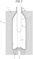
- FIGS. 1 and 2 illustrate an example of a liquid blow molding apparatus configured to stretch a preform into a container by liquid blow molding.
- FIG. 1 illustrates the state where a preform P, which has been preformed in a bottomed tubular shape (test-tube shape) and heated, is attached to a liquid blow molding apparatus 11, and
- FIG. 2 illustrates the state where a container B has been molded by liquid blow molding from the state of FIG. 1 .
- the liquid blow molding apparatus 11 includes, as a blow mold, a main split mold 1 and a bottom mold 3.
- the liquid blow molding apparatus 11 further includes a support pin 5 inside the blow mold.
- the main split mold 1 sandwiches a lower side of a neck ring P2 and an upper end of a trunk P3 of the preform P.
- the illustrated main split mold 1 and the bottom mold 3 are merely illustrative, and other configurations are also considered.
- the main split mold 1 and the bottom mold 3 may be integrated.
- the support pin 5 is disposed in the middle of the bottom mold 3.
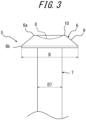
- the support pin 5 includes a head 6, which is configured to support a bottom P4 of the preform P from the outer side of the preform P, and a shaft 7, which is connected to the head 6 and which is displaceable upward and downward in the axial direction of the preform P.
- the head 6 has an upper end 6a, which is configured to support the bottom P4 of the preform P, and a lower end 6b, which is connected to the shaft 7.
- the head 6 is provided in the middle thereof with a concave portion 8, which has a shape corresponding to the bottom P4 of the preform P and which is configured to receive at least a part of the bottom P4 of the preform P.
- the surface of the concave portion 8 is configured to conform to a curved outer surface of the bottom P4 of the preform P.
- the head 6 is further provided, on the outer side of the concave portion 8 in the radial direction, with a umbrella-shaped inclined surface 9, which extends toward the end 6b in a manner such that the inclined surface 9 spreads out like an open fan.
- the head 6 and the shaft 7 may be formed as separate members.
- the shape of the support pin 5 may be altered as appropriate.
- the support pin 5 may have a columnar shape having a flat upper surface or a shape having a convex upper surface.
- the shape of the support pin 5 may confirm to the shape of the bottom P4 of the preform P, this is optional.
- the support pin 5 is configured to define a gap C between the head 6 and the bottom P4 of the preform P in the ascended position where the preform P is placed in the blow mold and where the support pin 5 is displaced upward.
- the support pin 5 comes into contact with the bottom P4 of the preform P to start to support the bottom P4. That is to say, the support pin 5 is configured to support the bottom P4 of the preform P at the time of a molding process (during stretching).
- the support pin 5 is also configured to be displaced downward in accordance with the axial stretching and deformation of the preform P caused by liquid blow molding.
- the preform P is stretched in the axial direction by pushing down the bottom P4 from the inner surface side by displacing the stretching rod R, which is disposed above the blow mold, downward in the axial direction and inserting the stretching rod R into the preform P through the mouth P1.
- the stretching rod R By sandwiching the bottom P4 of the preform P by the stretching rod R and the support pin 5, the effect of preventing core misalignment is enhanced.
- liquid that has been pressurized to a predetermined pressure is supplied into the preform P through the mouth P1 of the preform P while the preform P is being stretched in the axial direction by the stretching rod R.
- the preform P is stretched (expanded) in both the axis and the radial direction and blow molded into the state illustrated in FIG. 2 .
- the preform P may be stretched in the axial and the radial direction and blow molded into the state illustrated in FIG. 2 by supplying liquid that has been pressurized to a predetermined pressure into the preform P.
- the support pin 5 is configured to be displaced downward toward the bottom mold 3 in accordance with the axial deformation (stretching) of the preform P caused by blow molding, that is, in accordance with the pressure of the stretching rod R and the pressure of liquid inside the preform P.
- the liquid blow molding apparatus 11 preferably includes a resistance providing means (which is not illustrated) configured to provide resistance to the preform P when the support pin 5 is displaced downward.
- the resistance providing means may include a servo motor, a hydraulic means, a spring, and an air cylinder.
- the molded container B is formed to have a desired thickness, and molding defects are reduced.
- the preform P may be pinched by the mold during mold closing in the contacting state.
- the liquid supplying nozzle may come into contact with the mouth P1 or the like of the preform P, thereby causing deformation, damage, or the like to the preform P when the preform P is being protruded toward the outer side of mold and when the liquid supplying nozzle is being displaced downward.
- providing the gap C prevents misalignment of the preform P in the axial direction, and accordingly, there is no possibility of the aforementioned pinching of the preform P by the mold and the deformation, damage, or the like to the preform P due to contact with the nozzle.
- providing the head 6 of the support pin 5 with the concave portion 8, which is configured to receive the bottom P4 of the preform P prevents core misalignment in which the center position is deviated in the radial direction when the preform P is stretched.
- providing the head 6 of the support pin 5 with the umbrella-shaped inclined surface 9, which extends to spread out like an open fan prevents the problem that would arise in cases where the support pin 5 is composed only of the shaft 7, that is, the problem that resin may flow around down to (may be caught in) a side surface of the shaft 7, thereby reducing the occurrence of molding defects, such as thickness variation (thickness deviation), breakage, and wrinkles, in the bottom of the container B.
- the gap C is preferably as close to 0 mm as possible, while a variation in dimension of the preform P in molding and a change in dimension of the preform P due to heating are to be taken into consideration.
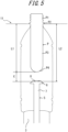
- the gap C is preferably 0.44 times or less the axial length (below-neck length) L1 (mm) (refer to FIG. 5 ) from the neck ring P2 to an end of the bottom P4 in the preform P.
- At least one of the support pin 5 and the stretching rod R is preferably configured to be always in contact with the bottom P4 of the preform P while liquid is being supplied into the preform P.
- the stretching rod R may come off from an inner surface of the bottom P4 of the preform P in the middle of liquid blowing. Even in such cases, core misalignment is prevented by the support pin 5 being always in contact with the bottom P4 of the preform P.
- a content liquid such as a beverage
- a content liquid such as a beverage
- the process of supplying the content liquid to the container B may be omitted, and the production process and the configuration of the blow molding apparatus may be simplified.
- blow molding may be achieved without using the stretching rod R.
- the stretching rod R In cases where the stretching rod R is used, blow liquid is flown to the mouth P1 of the preform P through an area obtained by deducting a sectional area of the stretching rod R from an opening area of the mouth P1 of the preform P.
- the stretching rod R in cases where the stretching rod R is not used, blow liquid is flown through the entire opening area of the mouth P1 of the preform P. Accordingly, the pressurization rate may be increased, and consequently, molding time may be reduced.
- the diameter D of an edge portion of the inclined surface 9 on the side of the end 6b is preferably greater than the diameter D7 of the shaft 7. The above configuration further prevents the problem that resin of the preform P may flow around down to the side surface of the shaft 7.
- the head 6 is preferably provided with an annular flat portion 10, which is formed between the concave portion 8 and the inclined surface 9.
- annular flat portion 10 which is formed between the concave portion 8 and the inclined surface 9.
- the head 6 of the support pin 5 may be shaped in a reversed bowl shape, and the inclined surface 9 may be formed as a curved surface having a curvature whose center lies within the head 6.
- the inclined surface 9 may be formed as a curved surface having a curvature whose center lies outside the head 6.
- the head 6 may be shaped in a shape (truncated pyramidal shape) obtained by removing a top portion from a pyramidal shape as illustrated in FIG. 4C .
- FIG. 4C illustrates a hexagonal pyramid, the number of side surfaces may be determined at will.
- the inclined surface 9 may be shaped like an umbrella gear.
- the concave portion 8 is formed at the center of the head 6 in the aforementioned examples, as illustrated in FIG. 4E , the concave portion 8 may be formed at a position eccentric from the center of the head 6. That is to say, as long as the center axis of the preform P is aligned with the center axes of the concave portion 8 and the shaft 7, the inclined surface 9 may be disposed to be eccentric as illustrated in FIG. 4E .
- Containers B were molded from preforms P by liquid blow molding under different conditions by using the liquid blow molding apparatus 11 according to the present disclosure, and whether the molded containers B had desired dimensions was confirmed.
- Table 1 depicts the volumes (ml) of the molded containers B, axial lengths (below-neck lengths) L1 (mm) (refer to FIG. 5 ) from the neck rings P2 to the ends of the bottoms P4 of the preforms P, the gaps C (mm) between the preforms P and the support pin 5 when the preforms P were placed in the blow mold, lengths L2 (mm) (refer to FIG.
- a draw ratio in the axial direction refers to a ratio between the length L1 before blow molding and the length L2, which is obtained by summing the length L1 and the gap C, and represents how much the preform P is stretched in the axial direction before the preform P comes into contact with the support pin 5.
- the results of Table 1 are defined as "good” when molding into substantially desired dimensions was achieved although a slight variation in dimensions and core misalignment within a range tolerable at the product level occurred and are defined as "very good” when molding at an even higher dimensional accuracy was achieved.
- the present disclosure provides a liquid blow molding method, which reduces mold defects by preventing core misalignment and by preventing a partial temperature drop in the preform and misalignment of the preform with respect to the blow mold during molding of the preform.
Landscapes
- Engineering & Computer Science (AREA)
- Manufacturing & Machinery (AREA)
- Mechanical Engineering (AREA)
- Blow-Moulding Or Thermoforming Of Plastics Or The Like (AREA)
- Moulds For Moulding Plastics Or The Like (AREA)
- Containers Having Bodies Formed In One Piece (AREA)
Claims (3)
- Ein Flüssigblasformverfahren zum Flüssigblasformen eines Vorformlings (P) zu einem Behälter (B) in einem Blasformkörper (1, 3), wobei der Vorformling (P) zu einer röhrenförmigen Form mit Boden geformt worden ist, wobei das Flüssigblasformverfahren Folgendes beinhaltet:Verwenden einer Flüssigblasformvorrichtung (11), die einen Stützstift (5) beinhaltet, der einen Kopf (6) umfasst, der in dem Blasformkörper (1, 3) angeordnet ist,um einen Boden (P4) des Vorformlings (P) durch den Stützstift (5) durch das In-Kontakt-Bringen des Kopfes (6) des Stützstifts (5) und des Bodens (P4) des Vorformlings (P) zu einer Zeit des Lieferns einer Flüssigkeit in den Vorformling (P) in einem Formprozess zu stützen und den Stützstift (5) gemäß der Deformation des Vorformlings (P), die durch Flüssigblasformung bewirkt wird, nach unten zu verschieben, wobeider Kopf (6) des Stützstifts (5) konfiguriert ist, um den Boden (P4) des Vorformlings (P) von einer äußeren Seite des Vorformlings (P) zu stützen und der Stützstift (5) einen Schaft (7) umfasst, der mit dem Kopf (6) verbunden ist und der in einer axialen Richtung des Vorformlings (P) nach oben und nach unten verschoben werden kann,
undder Stützstift (5) konfiguriert ist, um in einer ausgefahrenen Position, in der der Vorformling (P) in dem Blasformkörper (1, 3) platziert ist und in der der Stützstift (5) nach oben verschoben ist, einen Spalt (C) zwischen dem Kopf (6) und dem Boden (P4) des Vorformlings (P) zu definieren,dadurch gekennzeichnet, dassder Spalt (C) und eine Länge (L1) unter dem Hals, die eine axiale Länge von einer unteren Oberfläche eines Halsrings (P2) zu einem Ende des Bodens (P4) des Vorformlings (P) ist, der folgenden Formel (A) genügen:
- Flüssigblasformverfahren gemäß Anspruch 1, wobei der Vorformling (P) durch Verwendung einer Dehnungsstange (R), die in der Flüssigblasformvorrichtung (11) umfasst ist, in der axialen Richtung gedehnt wird.
- Flüssigblasformverfahren gemäß Anspruch 2, wobei mindestens eines von dem Stützstift (5) und der Dehnungsstange (R) konfiguriert ist, um immer in Kontakt mit dem Boden (P4) des Vorformlings (P) zu sein, während Flüssigkeit in den Vorformling (P) geliefert wird.
Applications Claiming Priority (2)
| Application Number | Priority Date | Filing Date | Title |
|---|---|---|---|
| JP2015093369A JP6437379B2 (ja) | 2015-04-30 | 2015-04-30 | 液体ブロー成形装置および液体ブロー成形方法 |
| PCT/JP2016/001350 WO2016174808A1 (ja) | 2015-04-30 | 2016-03-10 | 液体ブロー成形装置および液体ブロー成形方法 |
Publications (3)
| Publication Number | Publication Date |
|---|---|
| EP3292983A1 EP3292983A1 (de) | 2018-03-14 |
| EP3292983A4 EP3292983A4 (de) | 2019-02-20 |
| EP3292983B1 true EP3292983B1 (de) | 2025-01-22 |
Family
ID=57198254
Family Applications (1)
| Application Number | Title | Priority Date | Filing Date |
|---|---|---|---|
| EP16786090.7A Active EP3292983B1 (de) | 2015-04-30 | 2016-03-10 | Flüssigblasvorrichtung und flüssigsblasformverfahren |
Country Status (5)
| Country | Link |
|---|---|
| US (1) | US10654212B2 (de) |
| EP (1) | EP3292983B1 (de) |
| JP (1) | JP6437379B2 (de) |
| CN (1) | CN107683199A (de) |
| WO (1) | WO2016174808A1 (de) |
Families Citing this family (7)
| Publication number | Priority date | Publication date | Assignee | Title |
|---|---|---|---|---|
| FR3076818B1 (fr) * | 2018-01-18 | 2019-12-13 | Sidel Participations | Recipient comprenant un fond voute presentant des bossages de rigidification repartis en bandes annulaires imbriquees |
| DE102018125794A1 (de) * | 2018-10-17 | 2020-04-23 | Krones Ag | Formfüllen mit anschließender Verschließung unter Innendruck |
| CN109454851B (zh) * | 2018-12-13 | 2021-06-01 | 广东星联精密机械有限公司 | 一种轴向双方向定位拉伸中空吹塑成型方法 |
| CN109454855B (zh) * | 2018-12-30 | 2024-04-02 | 广东星联精密机械有限公司 | 一种轴向双方向定位拉伸中空吹塑成型模具 |
| CN110303664A (zh) * | 2019-07-24 | 2019-10-08 | 广东星联精密机械有限公司 | 一种配备加热拉伸系统的吹塑成型模具及方法 |
| JP7693494B2 (ja) * | 2021-09-30 | 2025-06-17 | 株式会社吉野工業所 | 液体入り容器の製造方法 |
| CN115214110B (zh) * | 2022-07-28 | 2026-05-01 | 苏州星贝尔中空成型设备有限公司 | 一种中空吹塑机中的在线旋转瓶口切割装置 |
Family Cites Families (29)
| Publication number | Priority date | Publication date | Assignee | Title |
|---|---|---|---|---|
| US4036573A (en) | 1973-11-14 | 1977-07-19 | Monsanto Company | Stretch blow molding apparatus |
| US3993427A (en) * | 1974-10-11 | 1976-11-23 | Monsanto Company | Movable preform locator and blow air valve apparatus for a blow molding machine |
| DE2742693C2 (de) * | 1977-09-22 | 1983-08-11 | Gildemeister Corpoplast Gmbh, 2000 Hamburg | Maschine zum Blasformen von Hohlkörpern, insbesondere von Flaschen, aus thermoplastischem Kunststoff |
| US4233021A (en) * | 1978-03-30 | 1980-11-11 | Emhart Industries, Inc. | Plastic bottle forming machine |
| JPS58123029U (ja) * | 1982-02-15 | 1983-08-22 | 株式会社吉野工業所 | 2軸延伸ブロ−成形機における底部金型装置 |
| DE3363881D1 (en) * | 1982-04-12 | 1986-07-10 | Siegfried Shankar Roy | Injection blow molding apparatus |
| JPH0681700B2 (ja) * | 1990-09-25 | 1994-10-19 | 東洋製罐株式会社 | 二軸延伸プラスチックボトルの製造方法 |
| US5290506A (en) * | 1991-04-30 | 1994-03-01 | Nissei Asb Machine Co., Ltd. | Process of injection stretch blow molding hollow article having thick-walled bottom |
| JPH0524099A (ja) * | 1991-07-18 | 1993-02-02 | Denki Kagaku Kogyo Kk | 二軸延伸ブロー成形方法及びそのブロー金型 |
| US5403177A (en) * | 1993-07-16 | 1995-04-04 | Jomar Corporation | Injection stretch blow molding machine |
| FR2714631B1 (fr) * | 1993-12-30 | 1996-03-01 | Sidel Sa | Procédé et installation pour la fabrication de récipients, notamment de bouteilles, en matériau thermoplastique. |
| CH692492A5 (fr) * | 1998-03-25 | 2002-07-15 | Tetra Pak Plastics Ltd Tetra P | Machine de moulage par étirage-soufflage. |
| JP4126650B2 (ja) * | 2002-09-30 | 2008-07-30 | 株式会社吉野工業所 | 合成樹脂製壜体 |
| AU2003205489A1 (en) * | 2002-11-05 | 2004-06-07 | Netstal-Maschinen Ag | Method and device for the secondary treatment and the cooling of preforms |
| US9707711B2 (en) * | 2006-04-07 | 2017-07-18 | Graham Packaging Company, L.P. | Container having outwardly blown, invertible deep-set grips |
| JP4863114B2 (ja) * | 2006-10-27 | 2012-01-25 | 東洋製罐株式会社 | レトルト処理済みが確認可能な熱可塑性樹脂容器及びその容器の製造方法 |
| EP2143545A1 (de) * | 2008-07-07 | 2010-01-13 | Nestec S.A. | Verfahren und Vorrichtung zum Abfüllen von flüssigen Lebensmitteln |
| EP2143544A1 (de) * | 2008-07-07 | 2010-01-13 | Nestec S.A. | Verfahren und Vorrichtung zum Abfüllen von flüssigen Lebensmitteln |
| CN102497968B (zh) * | 2008-12-12 | 2014-08-27 | Mht模具及热转子技术股份公司 | 用于预制件的后处理及传递的系统 |
| US9314955B2 (en) * | 2010-10-15 | 2016-04-19 | Discma Ag | Use of optimized piston member for generating peak liquid pressure |
| US8968636B2 (en) * | 2010-10-15 | 2015-03-03 | Discma Ag | Stretch rod system for liquid or hydraulic blow molding |
| FR2975331B1 (fr) * | 2011-05-19 | 2014-03-07 | Sidel Participations | Procede d'etirage soufflage d'un recipient, comprenant une retraction de la tige d'etirage au cours d'une operation de boxage |
| JP5188610B2 (ja) * | 2011-07-13 | 2013-04-24 | 三菱電機株式会社 | 誘導加熱調理器 |
| CN104010792A (zh) * | 2011-10-27 | 2014-08-27 | 阿美科有限责任公司 | 反向拉伸连接杆和正向填充级控制杆 |
| CN104114348A (zh) | 2011-12-26 | 2014-10-22 | 株式会社吉野工业所 | 吹塑成型设备和吹塑成型方法 |
| JP5701809B2 (ja) * | 2012-03-30 | 2015-04-15 | 株式会社吉野工業所 | ブロー成形装置及びブロー成形方法 |
| JP5806929B2 (ja) * | 2011-12-27 | 2015-11-10 | 株式会社吉野工業所 | ブロー成形装置およびブロー成形容器の製造方法 |
| US9610744B2 (en) * | 2011-12-27 | 2017-04-04 | Discma Ag | Blow molding device and a method for manufacturing a container |
| EP3360843B1 (de) * | 2012-03-30 | 2020-07-15 | Discma AG | Verfahren zum setzen eines innenraums eines behälters unter überdruck |
-
2015
- 2015-04-30 JP JP2015093369A patent/JP6437379B2/ja active Active
-
2016
- 2016-03-10 US US15/570,695 patent/US10654212B2/en active Active
- 2016-03-10 EP EP16786090.7A patent/EP3292983B1/de active Active
- 2016-03-10 WO PCT/JP2016/001350 patent/WO2016174808A1/ja not_active Ceased
- 2016-03-10 CN CN201680024955.8A patent/CN107683199A/zh active Pending
Also Published As
| Publication number | Publication date |
|---|---|
| JP6437379B2 (ja) | 2018-12-12 |
| US20180354187A1 (en) | 2018-12-13 |
| JP2016210031A (ja) | 2016-12-15 |
| CN107683199A (zh) | 2018-02-09 |
| EP3292983A1 (de) | 2018-03-14 |
| EP3292983A4 (de) | 2019-02-20 |
| US10654212B2 (en) | 2020-05-19 |
| WO2016174808A1 (ja) | 2016-11-03 |
Similar Documents
| Publication | Publication Date | Title |
|---|---|---|
| EP3292983A1 (de) | Flüssigblasvorrichtung und flüssigsblasformverfahren | |
| CN104136195B (zh) | 吹塑成型装置和容器的制造方法 | |
| RU2577270C2 (ru) | Вытяжное стержневое приспособление для жидкостного или гидравлического формования с раздувом | |
| WO2013099120A1 (ja) | ブロー成形装置およびブロー成形方法 | |
| EP2810763A1 (de) | Blasformvorrichtung | |
| CN109605716B (zh) | 成型模具以及注射成型模具 | |
| KR100189402B1 (ko) | 대형 용기의 연신취입성형방법 | |
| JP6633517B2 (ja) | 液体体積を供与する方法及び関連装置 | |
| CN110549539B (zh) | 对用于泵的引导杆进行制造的方法 | |
| US20200262128A1 (en) | Mold base provided with a central movable insert | |
| JP5567310B2 (ja) | 偏平容器のブロー成形方法 | |
| WO1995029804A1 (en) | Biaxial orientation blow molding method and preform holding jig | |
| EP3290180B1 (de) | Flüssigblasformvorrichtung | |
| CN105682889B (zh) | 吹塑成型装置 | |
| JP6727760B2 (ja) | 中空容器の製造方法及びブロー成形装置 | |
| US10076867B2 (en) | Method and device for the production of an optimized bottom contour on preforms | |
| CN107000262B (zh) | 用于在预制件上制造优化的颈部轮廓的方法和装置 | |
| CN113557114B (zh) | 容器的模具及容器的制造方法 | |
| EP3778185B1 (de) | Blasform und blasformvorrichtung | |
| EP3213901A1 (de) | Vorform für flüssiges blasformen | |
| JP7672757B1 (ja) | 中空成形体の成形方法、これに用いる延伸ロッドおよび射出延伸ブロー成形機 | |
| JP2021024199A (ja) | 多重ボトル製造方法及び多重ボトル用プリフォーム | |
| EP4470750A1 (de) | Thermoplastischer behälter und verfahren zur herstellung des thermoplastischen behälters | |
| JP5814779B2 (ja) | ブロー成形装置およびブロー成形方法 | |
| JP2025542472A (ja) | 延伸ブロー成形によって製造された容器を冷却する方法 |
Legal Events
| Date | Code | Title | Description |
|---|---|---|---|
| STAA | Information on the status of an ep patent application or granted ep patent |
Free format text: STATUS: THE INTERNATIONAL PUBLICATION HAS BEEN MADE |
|
| PUAI | Public reference made under article 153(3) epc to a published international application that has entered the european phase |
Free format text: ORIGINAL CODE: 0009012 |
|
| STAA | Information on the status of an ep patent application or granted ep patent |
Free format text: STATUS: REQUEST FOR EXAMINATION WAS MADE |
|
| 17P | Request for examination filed |
Effective date: 20171121 |
|
| AK | Designated contracting states |
Kind code of ref document: A1 Designated state(s): AL AT BE BG CH CY CZ DE DK EE ES FI FR GB GR HR HU IE IS IT LI LT LU LV MC MK MT NL NO PL PT RO RS SE SI SK SM TR |
|
| AX | Request for extension of the european patent |
Extension state: BA ME |
|
| DAV | Request for validation of the european patent (deleted) | ||
| DAX | Request for extension of the european patent (deleted) | ||
| A4 | Supplementary search report drawn up and despatched |
Effective date: 20190118 |
|
| RIC1 | Information provided on ipc code assigned before grant |
Ipc: B29C 49/46 20060101ALI20190114BHEP Ipc: B29C 49/06 20060101ALI20190114BHEP Ipc: B29C 49/12 20060101AFI20190114BHEP Ipc: B29L 31/00 20060101ALN20190114BHEP |
|
| STAA | Information on the status of an ep patent application or granted ep patent |
Free format text: STATUS: EXAMINATION IS IN PROGRESS |
|
| 17Q | First examination report despatched |
Effective date: 20200812 |
|
| REG | Reference to a national code |
Ref country code: DE Ref legal event code: R079 Free format text: PREVIOUS MAIN CLASS: B29C0049460000 Ipc: B29C0049120000 Ref document number: 602016091017 Country of ref document: DE |
|
| GRAP | Despatch of communication of intention to grant a patent |
Free format text: ORIGINAL CODE: EPIDOSNIGR1 |
|
| STAA | Information on the status of an ep patent application or granted ep patent |
Free format text: STATUS: GRANT OF PATENT IS INTENDED |
|
| RIC1 | Information provided on ipc code assigned before grant |
Ipc: B29L 31/00 20060101ALN20241025BHEP Ipc: B29C 49/06 20060101ALI20241025BHEP Ipc: B29C 49/46 20060101ALI20241025BHEP Ipc: B29C 49/12 20060101AFI20241025BHEP |
|
| INTG | Intention to grant announced |
Effective date: 20241107 |
|
| GRAS | Grant fee paid |
Free format text: ORIGINAL CODE: EPIDOSNIGR3 |
|
| GRAA | (expected) grant |
Free format text: ORIGINAL CODE: 0009210 |
|
| STAA | Information on the status of an ep patent application or granted ep patent |
Free format text: STATUS: THE PATENT HAS BEEN GRANTED |
|
| AK | Designated contracting states |
Kind code of ref document: B1 Designated state(s): AL AT BE BG CH CY CZ DE DK EE ES FI FR GB GR HR HU IE IS IT LI LT LU LV MC MK MT NL NO PL PT RO RS SE SI SK SM TR |
|
| REG | Reference to a national code |
Ref country code: GB Ref legal event code: FG4D |
|
| REG | Reference to a national code |
Ref country code: CH Ref legal event code: EP |
|
| REG | Reference to a national code |
Ref country code: IE Ref legal event code: FG4D |
|
| REG | Reference to a national code |
Ref country code: DE Ref legal event code: R096 Ref document number: 602016091017 Country of ref document: DE |
|
| REG | Reference to a national code |
Ref country code: NL Ref legal event code: MP Effective date: 20250122 |
|
| PG25 | Lapsed in a contracting state [announced via postgrant information from national office to epo] |
Ref country code: NL Free format text: LAPSE BECAUSE OF FAILURE TO SUBMIT A TRANSLATION OF THE DESCRIPTION OR TO PAY THE FEE WITHIN THE PRESCRIBED TIME-LIMIT Effective date: 20250122 |
|
| PG25 | Lapsed in a contracting state [announced via postgrant information from national office to epo] |
Ref country code: RS Free format text: LAPSE BECAUSE OF FAILURE TO SUBMIT A TRANSLATION OF THE DESCRIPTION OR TO PAY THE FEE WITHIN THE PRESCRIBED TIME-LIMIT Effective date: 20250422 |
|
| PG25 | Lapsed in a contracting state [announced via postgrant information from national office to epo] |
Ref country code: FI Free format text: LAPSE BECAUSE OF FAILURE TO SUBMIT A TRANSLATION OF THE DESCRIPTION OR TO PAY THE FEE WITHIN THE PRESCRIBED TIME-LIMIT Effective date: 20250122 |
|
| PG25 | Lapsed in a contracting state [announced via postgrant information from national office to epo] |
Ref country code: PL Free format text: LAPSE BECAUSE OF FAILURE TO SUBMIT A TRANSLATION OF THE DESCRIPTION OR TO PAY THE FEE WITHIN THE PRESCRIBED TIME-LIMIT Effective date: 20250122 |
|
| PGFP | Annual fee paid to national office [announced via postgrant information from national office to epo] |
Ref country code: DE Payment date: 20250331 Year of fee payment: 10 |
|
| PG25 | Lapsed in a contracting state [announced via postgrant information from national office to epo] |
Ref country code: ES Free format text: LAPSE BECAUSE OF FAILURE TO SUBMIT A TRANSLATION OF THE DESCRIPTION OR TO PAY THE FEE WITHIN THE PRESCRIBED TIME-LIMIT Effective date: 20250122 |
|
| REG | Reference to a national code |
Ref country code: LT Ref legal event code: MG9D |
|
| PG25 | Lapsed in a contracting state [announced via postgrant information from national office to epo] |
Ref country code: NO Free format text: LAPSE BECAUSE OF FAILURE TO SUBMIT A TRANSLATION OF THE DESCRIPTION OR TO PAY THE FEE WITHIN THE PRESCRIBED TIME-LIMIT Effective date: 20250422 Ref country code: IS Free format text: LAPSE BECAUSE OF FAILURE TO SUBMIT A TRANSLATION OF THE DESCRIPTION OR TO PAY THE FEE WITHIN THE PRESCRIBED TIME-LIMIT Effective date: 20250522 |
|
| REG | Reference to a national code |
Ref country code: AT Ref legal event code: MK05 Ref document number: 1761167 Country of ref document: AT Kind code of ref document: T Effective date: 20250122 |
|
| PG25 | Lapsed in a contracting state [announced via postgrant information from national office to epo] |
Ref country code: HR Free format text: LAPSE BECAUSE OF FAILURE TO SUBMIT A TRANSLATION OF THE DESCRIPTION OR TO PAY THE FEE WITHIN THE PRESCRIBED TIME-LIMIT Effective date: 20250122 |
|
| PG25 | Lapsed in a contracting state [announced via postgrant information from national office to epo] |
Ref country code: LV Free format text: LAPSE BECAUSE OF FAILURE TO SUBMIT A TRANSLATION OF THE DESCRIPTION OR TO PAY THE FEE WITHIN THE PRESCRIBED TIME-LIMIT Effective date: 20250122 Ref country code: PT Free format text: LAPSE BECAUSE OF FAILURE TO SUBMIT A TRANSLATION OF THE DESCRIPTION OR TO PAY THE FEE WITHIN THE PRESCRIBED TIME-LIMIT Effective date: 20250522 |
|
| PG25 | Lapsed in a contracting state [announced via postgrant information from national office to epo] |
Ref country code: GR Free format text: LAPSE BECAUSE OF FAILURE TO SUBMIT A TRANSLATION OF THE DESCRIPTION OR TO PAY THE FEE WITHIN THE PRESCRIBED TIME-LIMIT Effective date: 20250423 Ref country code: BG Free format text: LAPSE BECAUSE OF FAILURE TO SUBMIT A TRANSLATION OF THE DESCRIPTION OR TO PAY THE FEE WITHIN THE PRESCRIBED TIME-LIMIT Effective date: 20250122 |
|
| PG25 | Lapsed in a contracting state [announced via postgrant information from national office to epo] |
Ref country code: AT Free format text: LAPSE BECAUSE OF FAILURE TO SUBMIT A TRANSLATION OF THE DESCRIPTION OR TO PAY THE FEE WITHIN THE PRESCRIBED TIME-LIMIT Effective date: 20250122 |
|
| PG25 | Lapsed in a contracting state [announced via postgrant information from national office to epo] |
Ref country code: SE Free format text: LAPSE BECAUSE OF FAILURE TO SUBMIT A TRANSLATION OF THE DESCRIPTION OR TO PAY THE FEE WITHIN THE PRESCRIBED TIME-LIMIT Effective date: 20250122 |
|
| PG25 | Lapsed in a contracting state [announced via postgrant information from national office to epo] |
Ref country code: SM Free format text: LAPSE BECAUSE OF FAILURE TO SUBMIT A TRANSLATION OF THE DESCRIPTION OR TO PAY THE FEE WITHIN THE PRESCRIBED TIME-LIMIT Effective date: 20250122 |
|
| PG25 | Lapsed in a contracting state [announced via postgrant information from national office to epo] |
Ref country code: DK Free format text: LAPSE BECAUSE OF FAILURE TO SUBMIT A TRANSLATION OF THE DESCRIPTION OR TO PAY THE FEE WITHIN THE PRESCRIBED TIME-LIMIT Effective date: 20250122 |
|
| PG25 | Lapsed in a contracting state [announced via postgrant information from national office to epo] |
Ref country code: MC Free format text: LAPSE BECAUSE OF FAILURE TO SUBMIT A TRANSLATION OF THE DESCRIPTION OR TO PAY THE FEE WITHIN THE PRESCRIBED TIME-LIMIT Effective date: 20250122 |
|
| PG25 | Lapsed in a contracting state [announced via postgrant information from national office to epo] |
Ref country code: IT Free format text: LAPSE BECAUSE OF FAILURE TO SUBMIT A TRANSLATION OF THE DESCRIPTION OR TO PAY THE FEE WITHIN THE PRESCRIBED TIME-LIMIT Effective date: 20250122 |
|
| PG25 | Lapsed in a contracting state [announced via postgrant information from national office to epo] |
Ref country code: EE Free format text: LAPSE BECAUSE OF FAILURE TO SUBMIT A TRANSLATION OF THE DESCRIPTION OR TO PAY THE FEE WITHIN THE PRESCRIBED TIME-LIMIT Effective date: 20250122 Ref country code: CZ Free format text: LAPSE BECAUSE OF FAILURE TO SUBMIT A TRANSLATION OF THE DESCRIPTION OR TO PAY THE FEE WITHIN THE PRESCRIBED TIME-LIMIT Effective date: 20250122 |
|
| REG | Reference to a national code |
Ref country code: CH Ref legal event code: H13 Free format text: ST27 STATUS EVENT CODE: U-0-0-H10-H13 (AS PROVIDED BY THE NATIONAL OFFICE) Effective date: 20251023 Ref country code: DE Ref legal event code: R097 Ref document number: 602016091017 Country of ref document: DE |
|
| PG25 | Lapsed in a contracting state [announced via postgrant information from national office to epo] |
Ref country code: RO Free format text: LAPSE BECAUSE OF FAILURE TO SUBMIT A TRANSLATION OF THE DESCRIPTION OR TO PAY THE FEE WITHIN THE PRESCRIBED TIME-LIMIT Effective date: 20250122 |
|
| PG25 | Lapsed in a contracting state [announced via postgrant information from national office to epo] |
Ref country code: SK Free format text: LAPSE BECAUSE OF FAILURE TO SUBMIT A TRANSLATION OF THE DESCRIPTION OR TO PAY THE FEE WITHIN THE PRESCRIBED TIME-LIMIT Effective date: 20250122 |
|
| PG25 | Lapsed in a contracting state [announced via postgrant information from national office to epo] |
Ref country code: LU Free format text: LAPSE BECAUSE OF NON-PAYMENT OF DUE FEES Effective date: 20250310 |
|
| PLBE | No opposition filed within time limit |
Free format text: ORIGINAL CODE: 0009261 |
|
| STAA | Information on the status of an ep patent application or granted ep patent |
Free format text: STATUS: NO OPPOSITION FILED WITHIN TIME LIMIT |
|
| REG | Reference to a national code |
Ref country code: BE Ref legal event code: MM Effective date: 20250331 |
|
| GBPC | Gb: european patent ceased through non-payment of renewal fee |
Effective date: 20250422 |
|
| 26N | No opposition filed |
Effective date: 20251023 |
|
| PG25 | Lapsed in a contracting state [announced via postgrant information from national office to epo] |
Ref country code: GB Free format text: LAPSE BECAUSE OF NON-PAYMENT OF DUE FEES Effective date: 20250422 |
|
| PG25 | Lapsed in a contracting state [announced via postgrant information from national office to epo] |
Ref country code: BE Free format text: LAPSE BECAUSE OF NON-PAYMENT OF DUE FEES Effective date: 20250331 |
|
| PG25 | Lapsed in a contracting state [announced via postgrant information from national office to epo] |
Ref country code: CH Free format text: LAPSE BECAUSE OF NON-PAYMENT OF DUE FEES Effective date: 20250331 |
|
| PG25 | Lapsed in a contracting state [announced via postgrant information from national office to epo] |
Ref country code: IE Free format text: LAPSE BECAUSE OF NON-PAYMENT OF DUE FEES Effective date: 20250310 |
|
| PGFP | Annual fee paid to national office [announced via postgrant information from national office to epo] |
Ref country code: FR Payment date: 20260327 Year of fee payment: 11 |