EP3291908B1 - Abscheidevorrichtung zum abscheiden von partikeln aus einem luftstrom - Google Patents
Abscheidevorrichtung zum abscheiden von partikeln aus einem luftstrom Download PDFInfo
- Publication number
- EP3291908B1 EP3291908B1 EP16726511.5A EP16726511A EP3291908B1 EP 3291908 B1 EP3291908 B1 EP 3291908B1 EP 16726511 A EP16726511 A EP 16726511A EP 3291908 B1 EP3291908 B1 EP 3291908B1
- Authority
- EP
- European Patent Office
- Prior art keywords
- air flow
- particles
- separator
- separating
- cyclone separator
- Prior art date
- Legal status (The legal status is an assumption and is not a legal conclusion. Google has not performed a legal analysis and makes no representation as to the accuracy of the status listed.)
- Active
Links
Images
Classifications
-
- B—PERFORMING OPERATIONS; TRANSPORTING
- B01—PHYSICAL OR CHEMICAL PROCESSES OR APPARATUS IN GENERAL
- B01D—SEPARATION
- B01D50/00—Combinations of methods or devices for separating particles from gases or vapours
- B01D50/20—Combinations of devices covered by groups B01D45/00 and B01D46/00
-
- B—PERFORMING OPERATIONS; TRANSPORTING
- B01—PHYSICAL OR CHEMICAL PROCESSES OR APPARATUS IN GENERAL
- B01D—SEPARATION
- B01D45/00—Separating dispersed particles from gases or vapours by gravity, inertia, or centrifugal forces
- B01D45/12—Separating dispersed particles from gases or vapours by gravity, inertia, or centrifugal forces by centrifugal forces
- B01D45/16—Separating dispersed particles from gases or vapours by gravity, inertia, or centrifugal forces by centrifugal forces generated by the winding course of the gas stream, the centrifugal forces being generated solely or partly by mechanical means, e.g. fixed swirl vanes
-
- B—PERFORMING OPERATIONS; TRANSPORTING
- B01—PHYSICAL OR CHEMICAL PROCESSES OR APPARATUS IN GENERAL
- B01D—SEPARATION
- B01D45/00—Separating dispersed particles from gases or vapours by gravity, inertia, or centrifugal forces
- B01D45/18—Cleaning-out devices
-
- B—PERFORMING OPERATIONS; TRANSPORTING
- B04—CENTRIFUGAL APPARATUS OR MACHINES FOR CARRYING-OUT PHYSICAL OR CHEMICAL PROCESSES
- B04C—APPARATUS USING FREE VORTEX FLOW, e.g. CYCLONES
- B04C3/00—Apparatus in which the axial direction of the vortex flow following a screw-thread type line remains unchanged ; Devices in which one of the two discharge ducts returns centrally through the vortex chamber, a reverse-flow vortex being prevented by bulkheads in the central discharge duct
- B04C3/06—Construction of inlets or outlets to the vortex chamber
-
- B—PERFORMING OPERATIONS; TRANSPORTING
- B04—CENTRIFUGAL APPARATUS OR MACHINES FOR CARRYING-OUT PHYSICAL OR CHEMICAL PROCESSES
- B04C—APPARATUS USING FREE VORTEX FLOW, e.g. CYCLONES
- B04C3/00—Apparatus in which the axial direction of the vortex flow following a screw-thread type line remains unchanged ; Devices in which one of the two discharge ducts returns centrally through the vortex chamber, a reverse-flow vortex being prevented by bulkheads in the central discharge duct
- B04C2003/003—Shapes or dimensions of vortex chambers
Definitions
- the invention relates to a rail vehicle with the features specified in the preamble of claim 1.
- Separating devices comprise a cyclone separator, a raw air duct leading to the cyclone separator for supplying a particle laden raw air flow and a clean air duct leading away from the cyclone separator for the purpose of continuing a clean air flow.
- the cyclone separator has a box-shaped separator housing with a plurality of separation cyclones passing through it for separating particles from the raw air flow into the separator housing and a discharge opening for discharging separated particles from the separator housing.
- Such separation devices are for example from the published patent applications DE 10 2005 026 811 A1 and DE 10 2012 011 358 A1 known.
- the raw air stream flowing into the separation cyclones is in each case set in a rotary motion by guide vanes, due to which the entrained particles are accelerated by the experienced centrifugal force in the direction of the pipe walls of the separation cyclones.
- the particles are collected on the pipe walls and removed through discharge windows in lower sections of the pipe walls.
- the cleaned air exits at the other ends of the separation cyclones as clean air flow while the separated particles fall gravitationally from the discharge windows down to the bottom of the separator housing.
- the invention has for its object to provide a rail vehicle of the type mentioned, the separation device with a more compact design cost and maintenance is less than the known separation device.
- the object is achieved by a rail vehicle of the type mentioned above with the features specified in the characterizing part of claim 1.
- the discharge opening is connected to a constriction of a venturi nozzle for sucking off a waste air stream enriched with discharged particles.
- the Venturi nozzle replaces the build-up discharge fan including its connections and control.
- the venturi is connected to the raw air duct via a branched off from this side channel.
- the required for generating the negative pressure in the bottleneck of the Venturi nozzle air flow is here branched off from the raw air flow in an advantageous manner, whereby a separate generation of this air flow can be omitted.
- the raw air flow to be generated thereby becomes somewhat larger, but can be accomplished by a slightly larger sized fan or a slightly higher fan speed; however, it can also be used reserves from a possible oversizing of the fan.
- a separator 1 for separating particles, for example dust or water particles, from a stream of air comprises a known cyclone separator 2.
- the cyclone separator 2 is arranged in the rectangular cross-section of an air duct, which is part of a cooling air system for supplying a machine room of a locomotive with a cooled air flow can be.
- the air channel has a raw air duct 3, through which a laden with particles Rohluftstrom 4 is led to the cyclone separator 2.
- the air duct has a clean air duct 5, through which a clean air flow 6 is led away from the cyclone separator 2.
- the cyclone separator 2 has a box-shaped separator housing 7.
- the separator housing 7 is penetrated by a plurality of aligned in the flow direction, mutually parallel Abscheidezyklonen 8, which are formed for the separation of particles from the raw air stream 4 in the separator housing 7.
- the particles deposited in the separation cyclones 8 fall on a bottom of the separator housing 7, in which a rectangular, the channel cross-section spanning, discharge opening 9 is located.
- Through the discharge opening 9 fallen particles are discharged from the separator housing 7 on the ground.
- branches off upstream of the cyclone 2 a side channel 13 from the raw air duct 3, the cross section of which initially tapers to a constriction 10 and then expanded again to an exhaust duct 14.
- This side channel construction forms a Venturi nozzle 11, the constriction 10 is connected via a discharge nozzle 15 with the discharge opening 9.
- the separation device 1 thus requires less space and is also by avoiding moving parts less maintenance and less susceptible to interference.
Landscapes
- Chemical & Material Sciences (AREA)
- Chemical Kinetics & Catalysis (AREA)
- Cyclones (AREA)
- Separating Particles In Gases By Inertia (AREA)
Description
- Die Erfindung betrifft ein Schienenfahrzeug mit den im Oberbegriff des Patentanspruches 1 angegebenen Merkmalen.
- Abscheidevorrichtungen umfassen einen Zyklonabscheider, einen zum Zyklonabscheider hinführenden Rohluftkanal zur Zuführung eines mit Partikeln beladenen Rohluftstroms und einen vom Zyklonabscheider wegführenden Reinluftkanal zum fortführen eines Reinluftstromes. Der Zyklonabscheider weist ein kastenförmiges Abscheidergehäuse mit einer Mehrzahl an dieses durchsetzenden Abscheidezyklonen zum Abscheiden von Partikeln aus dem Rohluftstrom in das Abscheidergehäuse und eine Austragsöffnung zum Austragen von abgeschiedenen Partikeln aus dem Abscheidergehäuse auf.
- Derartige Abscheidevorrichtungen sind beispielsweise aus den Offenlegungsschriften
DE 10 2005 026 811 A1 undDE 10 2012 011 358 A1 bekannt. Der in die Abscheidezyklone einströmende Rohluftstrom wird dort jeweils durch Leitschaufeln in eine Rotationsbewegung versetzt, aufgrund welcher die mitgeführten Partikel durch die erfahrene Fliehkraft in Richtung Rohrwandungen der Abscheidezyklone beschleunigt werden. Die Partikel werden an den Rohrwandungen gesammelt und durch Austragsfenster in unteren Abschnitten der Rohrwandungen entfernt. Die gereinigte Luft tritt an den anderen Enden der Abscheidezyklone als Reinluftstrom aus, während die abgeschiedenen Partikel schwerkraftgetrieben von den Austragsfenstern nach unten auf den Boden des Abscheidergehäuses fallen. Zum effektiven Abtransport der abgeschiedenen Partikel aus dem Abscheidergehäuse ist es beispielsweise aus der OffenlegungsschriftDE 10 1005 026 811 A1 bekannt, an die Austragsöffnung einen Austragslüfter anzuschließen, der zum Absaugen der Partikel einen Unterdruck an der Austragsöffnung erzeugt und diese über einen mit ausgetragenen Partikeln angereicherten Abluftstrom abzutransportieren. - Der Erfindung liegt die Aufgabe zugrunde, ein Schienenfahrzeug der eingangs genannten Art bereitzustellen, dessen Abscheidevorrichtung bei kompakterer Bauweise kostengünstiger und wartungsärmer als die bekannte Abscheidevorrichtung ist.
- Die Aufgabe wird erfindungsgemäß gelöst durch ein Schienenfahrzeug der eingangs genannten Art mit den im kennzeichnenden Teil des Patentanspruches 1 angegebenen Merkmalen. Die Abscheidevorrichtung zum Reinigen eines Luftstromes einer Kühlluftanlage zur Versorgung des Maschinenraums des Schienenfahrzeugs, insbesondere einer Lokomotive, angewandt. Erfindungsgemäß ist die Austragsöffnung mit einer Engstelle einer Venturidüse zum Absaugen eines mit ausgetragenen Partikeln angereicherten Abluftstroms verbunden. Die Venturidüse ersetzt den aufbauenden Austragslüfter einschließlich dessen Anschlüsse und Ansteuerung. Hierdurch wird die erfindungsgemäße Abscheidevorrichtung kompakter und durch den Wegfall des Austragslüfters auch kostengünstiger. Durch den Entfall des Austragslüfters sinkt die Anzahl beweglicher Teile, wodurch die erfindungsgemäße Abscheidevorrichtung auch wartungsärmer wird. Die Venturidüse ist mit dem Rohluftkanal über einen von diesem abgezweigten Seitenkanal verbunden. Der zum Erzeugen des Unterdruckes in der Engstelle der Venturidüse erforderliche Luftstrom wird hier in vorteilhafter Weise vom Rohluftstrom abgezweigt, wodurch eine gesonderte Erzeugung dieses Luftstroms entfallen kann. Der zu erzeugende Rohluftstrom wird hierdurch zwar etwas größer, kann aber durch einen geringfügig größer dimensionierten Lüfter oder eine etwas höhere Lüfterdrehzahl bewerkstelligt werden; es können allerdings hierfür auch Reserven aus einer möglichen Überdimensionierung des Lüfters genutzt werden.
- Weitere Eigenschaften und Vorteile der erfindungsgemäßen Abscheidevorrichtung ergeben sich aus nachfolgender Beschreibung eines Ausführungsbeispiels anhand der Zeichnungen, in deren
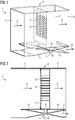
- FIG 1
- eine erfindungsgemäße Abscheidevorrichtung in perspektivischer Darstellung und
- FIG 2
- die Abscheidevorrichtung aus
FIG 1 in einem Längsschnitt - Gemäß
FIG 1 und FIG 2 umfasst eine Abscheidevorrichtung 1 zum Abscheiden von Partikeln, beispielsweise Staub- oder Wasserpartikel, aus einem Luftstrom einen an sich bekannten Zyklonabscheider 2. Der Zyklonabscheider 2 ist im rechteckigen Querschnitt eines Luftkanals angeordnet, der Teil einer Kühlluftanlage zur Versorgung eines Maschinenraums einer Lokomotive mit einem gekühlten Luftstrom sein kann. Der Luftkanal weist einen Rohluftkanal 3 auf, durch den ein mit Partikeln beladener Rohluftstrom 4 zum Zyklonabscheider 2 hingeführt wird. Des Weiteren weist der Luftkanal einen Reinluftkanal 5 auf, durch den ein Reinluftstrom 6 vom Zyklonabscheider 2 weggeführt wird. Der Zyklonabscheider 2 weist ein kastenförmiges Abscheidergehäuse 7 auf. Das Abscheidergehäuse 7 ist von einer Mehrzahl an in Strömungsrichtung ausgerichteten, parallel zueinander angeordneten Abscheidezyklonen 8 durchsetzt, die zum Abscheiden von Partikeln aus dem Rohluftstrom 4 in das Abscheidergehäuse 7 ausgebildet sind. Die in den Abscheidezyklonen 8 abgeschiedenen Partikel fallen auf einen Boden des Abscheidergehäuses 7, in dem sich eine rechteckige, den Kanalquerschnitt überspannende, Austragsöffnung 9 befindet. Durch die Austragsöffnung 9 werden auf den Boden gefallene Partikel aus dem Abscheidergehäuse 7 ausgetragen. Hierzu zweigt stromauf des Zyklonabscheiders 2 ein Seitenkanal 13 vom Rohluftkanal 3 ab, dessen Querschnitt sich zunächst bis zu einer Engstelle 10 verjüngt und anschließend wieder zu einem Abluftkanal 14 erweitert. Diese Seitenkanalkonstruktion bildet eine Venturidüse 11, deren Engstelle 10 über einen Austragsstutzen 15 mit der Austragsöffnung 9 verbunden ist. - Der in den Seitenkanal 13 abgezweigte Teil des Rohluftstromes 4 wird durch die Querschnittsverringerung derart beschleunigt, dass in der Engstelle 10 ein Unterdruck entsteht, durch den die abgeschiedenen Partikel aus dem Abscheidergehäuse 7 mit einem Abluftstrom 12 abgesaugt werden, der die Engstelle 10 über den Abluftkanal 14 verlässt.
- Auf diese Weise wird ein gesonderter Austragslüfter zur Erzeugung eines Unterdrucks am Austragsstutzen 15 ebenso eingespart, wie dessen Anschlüsse und Ansteuerung. Die erfindungsgemäße Abscheidevorrichtung 1 erfordert damit weniger Bauraum und ist auch durch Vermeidung beweglicher Teile wartungsärmer und weniger störanfällig.
Claims (1)
- Schienenfahrzeug, insbesondere Lokomotive, umfassend einen Maschinenraum und eine Kühlluftanlage zur Versorgung des Maschinenraums mit einem gekühlten Luftstrom sowie eine Abscheidevorrichtung (1) zum Abscheiden von Partikeln aus dem Luftstrom, dadurch gekennzeichnet, dass die Abscheidevorrichtung (1) einen Zyklonabscheider (2), einen zum Zyklonabscheider (2) hinführenden Rohluftkanal (3) zur Zuführung eines mit Partikeln beladenen Rohluftstroms (4) und einen vom Zyklonabscheider (2) wegführenden Reinluftkanal (5) zum Abführen eines Reinluftstroms (6) umfasst, wobei der Zyklonabscheider (2) ein kastenförmiges Abscheidergehäuse (7) mit einer Mehrzahl an dieses durchsetzenden Abscheidezyklonen (8) zum Abscheiden von Partikeln aus dem Rohluftstrom (4) in das Abscheidergehäuse (7) und eine Austragsöffnung (9) zum Austragen von abgeschiedenden Partikeln aus dem Abscheidergehäuse (7) aufweist, wobei die Austragsöffnung (9) mit einer Engstelle (10) einer Venturidüse (11) zum Absaugen eines mit ausgetragenen Partikeln angereicherten Abluftstromes (12) verbunden ist, und wobei die Venturidüse (11) mit dem Rohluftkanal (3) über einen von diesem abzweigenden Seitenkanal (13) verbunden ist.
Priority Applications (1)
| Application Number | Priority Date | Filing Date | Title |
|---|---|---|---|
| PL16726511T PL3291908T3 (pl) | 2015-07-01 | 2016-05-25 | Urządzenie oddzielające do oddzielania cząstek ze strumienia powietrza |
Applications Claiming Priority (2)
| Application Number | Priority Date | Filing Date | Title |
|---|---|---|---|
| DE102015212308 | 2015-07-01 | ||
| PCT/EP2016/061741 WO2017001121A1 (de) | 2015-07-01 | 2016-05-25 | Abscheidevorrichtung zum abscheiden von partikeln aus einem luftstrom |
Publications (2)
| Publication Number | Publication Date |
|---|---|
| EP3291908A1 EP3291908A1 (de) | 2018-03-14 |
| EP3291908B1 true EP3291908B1 (de) | 2019-03-06 |
Family
ID=56097088
Family Applications (1)
| Application Number | Title | Priority Date | Filing Date |
|---|---|---|---|
| EP16726511.5A Active EP3291908B1 (de) | 2015-07-01 | 2016-05-25 | Abscheidevorrichtung zum abscheiden von partikeln aus einem luftstrom |
Country Status (6)
| Country | Link |
|---|---|
| US (1) | US10835853B2 (de) |
| EP (1) | EP3291908B1 (de) |
| CN (1) | CN208389572U (de) |
| ES (1) | ES2729069T3 (de) |
| PL (1) | PL3291908T3 (de) |
| WO (1) | WO2017001121A1 (de) |
Families Citing this family (4)
| Publication number | Priority date | Publication date | Assignee | Title |
|---|---|---|---|---|
| DE102018212768A1 (de) * | 2018-07-31 | 2020-02-06 | Siemens Aktiengesellschaft | Verfahren zum Erzeugen einer Bewegungsinformation |
| WO2020046603A1 (en) * | 2018-08-27 | 2020-03-05 | Sierra Nevada Corporation | Low-gravity water capture device with water stabilization |
| DE102020200950A1 (de) * | 2020-01-27 | 2021-07-29 | Deere & Company | Absauganordnung für einen Zentrifugalluftfilter |
| US11938437B2 (en) | 2021-02-04 | 2024-03-26 | Transportation Ip Holdings, Llc | Filter system and method |
Family Cites Families (15)
| Publication number | Priority date | Publication date | Assignee | Title |
|---|---|---|---|---|
| DE837786C (de) | 1949-07-17 | 1952-05-02 | Gertrud Schnuerle | Luftfilter fuer Zweitakt-Geblaese-Motoren |
| US4247313A (en) * | 1979-08-20 | 1981-01-27 | Perry Equipment Corporation | Gas-particulate separator with pulse-jet cleanable filter elements |
| SE416989B (sv) | 1979-11-06 | 1981-02-16 | Saab Scania Ab | Arrangemang for rening av inloppsluft till en forbrenningsmotor |
| US4348057A (en) * | 1980-08-25 | 1982-09-07 | B & J Manufacturing Company | Blower and dust collecting machine and method of operation |
| US4746340A (en) * | 1986-10-28 | 1988-05-24 | Donaldson Company, Inc. | Air cleaner apparatus |
| DE68920912T2 (de) * | 1988-06-02 | 1995-05-24 | Cyclofil Pty Ltd | Wirbelrohr-Abscheider. |
| ZA931264B (en) * | 1992-02-27 | 1993-09-17 | Atomic Energy South Africa | Filtration. |
| US5472463A (en) * | 1994-06-14 | 1995-12-05 | Cummins Engine Company, Inc. | Pressure side integrated air filter and filtering networks for engines |
| DE10354401A1 (de) | 2003-03-14 | 2004-09-23 | Mann + Hummel Gmbh | Luftfilter |
| DE102005026811A1 (de) | 2005-06-09 | 2006-12-14 | Mann + Hummel Gmbh | Staubaustragssystem |
| US7682413B2 (en) | 2006-10-16 | 2010-03-23 | Deere & Company | Air precleaner arrangement for an internal combustion engine comprising two cyclone filters |
| DE202008017059U1 (de) | 2008-12-23 | 2010-05-12 | Mann + Hummel Gmbh | Filtereinrichtung für Brennkraftmaschinen |
| US8425641B2 (en) * | 2010-06-30 | 2013-04-23 | General Electric Company | Inlet air filtration system |
| FR2988307B1 (fr) * | 2012-03-26 | 2014-03-21 | Coutier Moulage Gen Ind | Separateur a cyclone |
| DE102012011358B4 (de) | 2012-06-11 | 2014-03-20 | Mann + Hummel Gmbh | Fliehkraftabscheider und Verfahren zum Herstellen eines Fliehkraftabscheiders |
-
2016
- 2016-05-25 PL PL16726511T patent/PL3291908T3/pl unknown
- 2016-05-25 ES ES16726511T patent/ES2729069T3/es active Active
- 2016-05-25 CN CN201690000960.0U patent/CN208389572U/zh not_active Expired - Fee Related
- 2016-05-25 WO PCT/EP2016/061741 patent/WO2017001121A1/de not_active Ceased
- 2016-05-25 US US15/741,367 patent/US10835853B2/en active Active
- 2016-05-25 EP EP16726511.5A patent/EP3291908B1/de active Active
Non-Patent Citations (1)
| Title |
|---|
| None * |
Also Published As
| Publication number | Publication date |
|---|---|
| WO2017001121A1 (de) | 2017-01-05 |
| CN208389572U (zh) | 2019-01-18 |
| PL3291908T3 (pl) | 2019-08-30 |
| EP3291908A1 (de) | 2018-03-14 |
| US10835853B2 (en) | 2020-11-17 |
| US20190015772A1 (en) | 2019-01-17 |
| ES2729069T3 (es) | 2019-10-30 |
Similar Documents
| Publication | Publication Date | Title |
|---|---|---|
| EP1541278B1 (de) | Zyklonabscheider | |
| DE102008055045A1 (de) | Staubsauger mit Fliehkraftabscheidern | |
| EP3291908B1 (de) | Abscheidevorrichtung zum abscheiden von partikeln aus einem luftstrom | |
| DE202010009611U1 (de) | Schweißrauchabsauganlage | |
| EP2932878B1 (de) | Zwei saugströme erzeugendes reinigungsgerät | |
| WO2018185268A1 (de) | Multizyklonabscheider eines mehrstufen-fluidfilters zur reinigung von gasförmigem fluid und mehrstufen-fluidfilter | |
| DE102015109999B4 (de) | Luftfilteranlage | |
| EP3090101B1 (de) | Saugsystem zur erzeugung eines saugstromes innerhalb einer saugstromleitung | |
| DE112016000194T5 (de) | Windkanalumlauf-Sichtvorrichtung für Schüttmaterial | |
| WO2000018490A1 (de) | Vorrichtung und verfahren zum abtrennen von teilchen aus einem fluid | |
| DE102020128539A1 (de) | Abscheider für Feststoffpartikel | |
| EP0125620A1 (de) | Luftfiltersystem | |
| CH665135A5 (de) | Fliehkraftabscheider. | |
| DE1906295C3 (de) | Entrippvorrichtung für Tabakblätter | |
| DE102006039647B4 (de) | Partikelabscheider | |
| DE112005002244B4 (de) | Klimakompressor mit Filter und Schmutzpartikelabscheider | |
| DE102010035184A1 (de) | Kühlvorrichtung von Kraftfahrzeug mit einer derartigen Kühlvorrichtung | |
| EP3508266B1 (de) | Trockenfilter mit erhöhter abscheideleistung und günstigen abmessungen | |
| WO2006008048A1 (de) | Partikelabscheider | |
| DE102008045613B4 (de) | Anlage zum Aufnehmen, Fördern und Abscheiden von Reststoffen | |
| DE102015110000B4 (de) | Materialvorabscheider | |
| EP2332626B1 (de) | Vorrichtung zum Abscheiden von Verunreinigungen aus einem Luftstrom | |
| DE10311406B4 (de) | Filteranordnung | |
| DE2364963A1 (de) | Geblaesefoerderer | |
| DE202015103277U1 (de) | Luftfilteranlage |
Legal Events
| Date | Code | Title | Description |
|---|---|---|---|
| STAA | Information on the status of an ep patent application or granted ep patent |
Free format text: STATUS: THE INTERNATIONAL PUBLICATION HAS BEEN MADE |
|
| PUAI | Public reference made under article 153(3) epc to a published international application that has entered the european phase |
Free format text: ORIGINAL CODE: 0009012 |
|
| STAA | Information on the status of an ep patent application or granted ep patent |
Free format text: STATUS: REQUEST FOR EXAMINATION WAS MADE |
|
| 17P | Request for examination filed |
Effective date: 20171204 |
|
| AK | Designated contracting states |
Kind code of ref document: A1 Designated state(s): AL AT BE BG CH CY CZ DE DK EE ES FI FR GB GR HR HU IE IS IT LI LT LU LV MC MK MT NL NO PL PT RO RS SE SI SK SM TR |
|
| AX | Request for extension of the european patent |
Extension state: BA ME |
|
| GRAP | Despatch of communication of intention to grant a patent |
Free format text: ORIGINAL CODE: EPIDOSNIGR1 |
|
| STAA | Information on the status of an ep patent application or granted ep patent |
Free format text: STATUS: GRANT OF PATENT IS INTENDED |
|
| DAV | Request for validation of the european patent (deleted) | ||
| DAX | Request for extension of the european patent (deleted) | ||
| INTG | Intention to grant announced |
Effective date: 20180928 |
|
| RAP1 | Party data changed (applicant data changed or rights of an application transferred) |
Owner name: SIEMENS MOBILITY GMBH |
|
| GRAS | Grant fee paid |
Free format text: ORIGINAL CODE: EPIDOSNIGR3 |
|
| GRAA | (expected) grant |
Free format text: ORIGINAL CODE: 0009210 |
|
| STAA | Information on the status of an ep patent application or granted ep patent |
Free format text: STATUS: THE PATENT HAS BEEN GRANTED |
|
| AK | Designated contracting states |
Kind code of ref document: B1 Designated state(s): AL AT BE BG CH CY CZ DE DK EE ES FI FR GB GR HR HU IE IS IT LI LT LU LV MC MK MT NL NO PL PT RO RS SE SI SK SM TR |
|
| REG | Reference to a national code |
Ref country code: GB Ref legal event code: FG4D Free format text: NOT ENGLISH |
|
| REG | Reference to a national code |
Ref country code: CH Ref legal event code: EP Ref country code: AT Ref legal event code: REF Ref document number: 1103789 Country of ref document: AT Kind code of ref document: T Effective date: 20190315 |
|
| REG | Reference to a national code |
Ref country code: DE Ref legal event code: R096 Ref document number: 502016003647 Country of ref document: DE |
|
| REG | Reference to a national code |
Ref country code: IE Ref legal event code: FG4D Free format text: LANGUAGE OF EP DOCUMENT: GERMAN |
|
| REG | Reference to a national code |
Ref country code: NL Ref legal event code: MP Effective date: 20190306 |
|
| REG | Reference to a national code |
Ref country code: LT Ref legal event code: MG4D |
|
| PG25 | Lapsed in a contracting state [announced via postgrant information from national office to epo] |
Ref country code: SE Free format text: LAPSE BECAUSE OF FAILURE TO SUBMIT A TRANSLATION OF THE DESCRIPTION OR TO PAY THE FEE WITHIN THE PRESCRIBED TIME-LIMIT Effective date: 20190306 Ref country code: LT Free format text: LAPSE BECAUSE OF FAILURE TO SUBMIT A TRANSLATION OF THE DESCRIPTION OR TO PAY THE FEE WITHIN THE PRESCRIBED TIME-LIMIT Effective date: 20190306 Ref country code: NO Free format text: LAPSE BECAUSE OF FAILURE TO SUBMIT A TRANSLATION OF THE DESCRIPTION OR TO PAY THE FEE WITHIN THE PRESCRIBED TIME-LIMIT Effective date: 20190606 Ref country code: FI Free format text: LAPSE BECAUSE OF FAILURE TO SUBMIT A TRANSLATION OF THE DESCRIPTION OR TO PAY THE FEE WITHIN THE PRESCRIBED TIME-LIMIT Effective date: 20190306 |
|
| PG25 | Lapsed in a contracting state [announced via postgrant information from national office to epo] |
Ref country code: BG Free format text: LAPSE BECAUSE OF FAILURE TO SUBMIT A TRANSLATION OF THE DESCRIPTION OR TO PAY THE FEE WITHIN THE PRESCRIBED TIME-LIMIT Effective date: 20190606 Ref country code: HR Free format text: LAPSE BECAUSE OF FAILURE TO SUBMIT A TRANSLATION OF THE DESCRIPTION OR TO PAY THE FEE WITHIN THE PRESCRIBED TIME-LIMIT Effective date: 20190306 Ref country code: NL Free format text: LAPSE BECAUSE OF FAILURE TO SUBMIT A TRANSLATION OF THE DESCRIPTION OR TO PAY THE FEE WITHIN THE PRESCRIBED TIME-LIMIT Effective date: 20190306 Ref country code: RS Free format text: LAPSE BECAUSE OF FAILURE TO SUBMIT A TRANSLATION OF THE DESCRIPTION OR TO PAY THE FEE WITHIN THE PRESCRIBED TIME-LIMIT Effective date: 20190306 Ref country code: GR Free format text: LAPSE BECAUSE OF FAILURE TO SUBMIT A TRANSLATION OF THE DESCRIPTION OR TO PAY THE FEE WITHIN THE PRESCRIBED TIME-LIMIT Effective date: 20190607 Ref country code: LV Free format text: LAPSE BECAUSE OF FAILURE TO SUBMIT A TRANSLATION OF THE DESCRIPTION OR TO PAY THE FEE WITHIN THE PRESCRIBED TIME-LIMIT Effective date: 20190306 |
|
| REG | Reference to a national code |
Ref country code: ES Ref legal event code: FG2A Ref document number: 2729069 Country of ref document: ES Kind code of ref document: T3 Effective date: 20191030 |
|
| PG25 | Lapsed in a contracting state [announced via postgrant information from national office to epo] |
Ref country code: RO Free format text: LAPSE BECAUSE OF FAILURE TO SUBMIT A TRANSLATION OF THE DESCRIPTION OR TO PAY THE FEE WITHIN THE PRESCRIBED TIME-LIMIT Effective date: 20190306 Ref country code: SK Free format text: LAPSE BECAUSE OF FAILURE TO SUBMIT A TRANSLATION OF THE DESCRIPTION OR TO PAY THE FEE WITHIN THE PRESCRIBED TIME-LIMIT Effective date: 20190306 Ref country code: PT Free format text: LAPSE BECAUSE OF FAILURE TO SUBMIT A TRANSLATION OF THE DESCRIPTION OR TO PAY THE FEE WITHIN THE PRESCRIBED TIME-LIMIT Effective date: 20190706 Ref country code: AL Free format text: LAPSE BECAUSE OF FAILURE TO SUBMIT A TRANSLATION OF THE DESCRIPTION OR TO PAY THE FEE WITHIN THE PRESCRIBED TIME-LIMIT Effective date: 20190306 Ref country code: EE Free format text: LAPSE BECAUSE OF FAILURE TO SUBMIT A TRANSLATION OF THE DESCRIPTION OR TO PAY THE FEE WITHIN THE PRESCRIBED TIME-LIMIT Effective date: 20190306 |
|
| PG25 | Lapsed in a contracting state [announced via postgrant information from national office to epo] |
Ref country code: SM Free format text: LAPSE BECAUSE OF FAILURE TO SUBMIT A TRANSLATION OF THE DESCRIPTION OR TO PAY THE FEE WITHIN THE PRESCRIBED TIME-LIMIT Effective date: 20190306 |
|
| REG | Reference to a national code |
Ref country code: DE Ref legal event code: R097 Ref document number: 502016003647 Country of ref document: DE |
|
| REG | Reference to a national code |
Ref country code: CH Ref legal event code: PL |
|
| PG25 | Lapsed in a contracting state [announced via postgrant information from national office to epo] |
Ref country code: IS Free format text: LAPSE BECAUSE OF FAILURE TO SUBMIT A TRANSLATION OF THE DESCRIPTION OR TO PAY THE FEE WITHIN THE PRESCRIBED TIME-LIMIT Effective date: 20190706 |
|
| PLBE | No opposition filed within time limit |
Free format text: ORIGINAL CODE: 0009261 |
|
| STAA | Information on the status of an ep patent application or granted ep patent |
Free format text: STATUS: NO OPPOSITION FILED WITHIN TIME LIMIT |
|
| PG25 | Lapsed in a contracting state [announced via postgrant information from national office to epo] |
Ref country code: DK Free format text: LAPSE BECAUSE OF FAILURE TO SUBMIT A TRANSLATION OF THE DESCRIPTION OR TO PAY THE FEE WITHIN THE PRESCRIBED TIME-LIMIT Effective date: 20190306 Ref country code: CH Free format text: LAPSE BECAUSE OF NON-PAYMENT OF DUE FEES Effective date: 20190531 Ref country code: LI Free format text: LAPSE BECAUSE OF NON-PAYMENT OF DUE FEES Effective date: 20190531 Ref country code: MC Free format text: LAPSE BECAUSE OF FAILURE TO SUBMIT A TRANSLATION OF THE DESCRIPTION OR TO PAY THE FEE WITHIN THE PRESCRIBED TIME-LIMIT Effective date: 20190306 |
|
| REG | Reference to a national code |
Ref country code: BE Ref legal event code: MM Effective date: 20190531 |
|
| 26N | No opposition filed |
Effective date: 20191209 |
|
| PG25 | Lapsed in a contracting state [announced via postgrant information from national office to epo] |
Ref country code: LU Free format text: LAPSE BECAUSE OF NON-PAYMENT OF DUE FEES Effective date: 20190525 Ref country code: SI Free format text: LAPSE BECAUSE OF FAILURE TO SUBMIT A TRANSLATION OF THE DESCRIPTION OR TO PAY THE FEE WITHIN THE PRESCRIBED TIME-LIMIT Effective date: 20190306 |
|
| PG25 | Lapsed in a contracting state [announced via postgrant information from national office to epo] |
Ref country code: TR Free format text: LAPSE BECAUSE OF FAILURE TO SUBMIT A TRANSLATION OF THE DESCRIPTION OR TO PAY THE FEE WITHIN THE PRESCRIBED TIME-LIMIT Effective date: 20190306 |
|
| PG25 | Lapsed in a contracting state [announced via postgrant information from national office to epo] |
Ref country code: IE Free format text: LAPSE BECAUSE OF NON-PAYMENT OF DUE FEES Effective date: 20190525 |
|
| PG25 | Lapsed in a contracting state [announced via postgrant information from national office to epo] |
Ref country code: BE Free format text: LAPSE BECAUSE OF NON-PAYMENT OF DUE FEES Effective date: 20190531 |
|
| PGFP | Annual fee paid to national office [announced via postgrant information from national office to epo] |
Ref country code: PL Payment date: 20200518 Year of fee payment: 5 |
|
| GBPC | Gb: european patent ceased through non-payment of renewal fee |
Effective date: 20200525 |
|
| PG25 | Lapsed in a contracting state [announced via postgrant information from national office to epo] |
Ref country code: GB Free format text: LAPSE BECAUSE OF NON-PAYMENT OF DUE FEES Effective date: 20200525 |
|
| PG25 | Lapsed in a contracting state [announced via postgrant information from national office to epo] |
Ref country code: CY Free format text: LAPSE BECAUSE OF FAILURE TO SUBMIT A TRANSLATION OF THE DESCRIPTION OR TO PAY THE FEE WITHIN THE PRESCRIBED TIME-LIMIT Effective date: 20190306 |
|
| PG25 | Lapsed in a contracting state [announced via postgrant information from national office to epo] |
Ref country code: HU Free format text: LAPSE BECAUSE OF FAILURE TO SUBMIT A TRANSLATION OF THE DESCRIPTION OR TO PAY THE FEE WITHIN THE PRESCRIBED TIME-LIMIT; INVALID AB INITIO Effective date: 20160525 Ref country code: MT Free format text: LAPSE BECAUSE OF FAILURE TO SUBMIT A TRANSLATION OF THE DESCRIPTION OR TO PAY THE FEE WITHIN THE PRESCRIBED TIME-LIMIT Effective date: 20190306 |
|
| PG25 | Lapsed in a contracting state [announced via postgrant information from national office to epo] |
Ref country code: MK Free format text: LAPSE BECAUSE OF FAILURE TO SUBMIT A TRANSLATION OF THE DESCRIPTION OR TO PAY THE FEE WITHIN THE PRESCRIBED TIME-LIMIT Effective date: 20190306 |
|
| REG | Reference to a national code |
Ref country code: AT Ref legal event code: MM01 Ref document number: 1103789 Country of ref document: AT Kind code of ref document: T Effective date: 20210525 |
|
| PG25 | Lapsed in a contracting state [announced via postgrant information from national office to epo] |
Ref country code: AT Free format text: LAPSE BECAUSE OF NON-PAYMENT OF DUE FEES Effective date: 20210525 |
|
| PG25 | Lapsed in a contracting state [announced via postgrant information from national office to epo] |
Ref country code: PL Free format text: LAPSE BECAUSE OF NON-PAYMENT OF DUE FEES Effective date: 20210525 |
|
| PGFP | Annual fee paid to national office [announced via postgrant information from national office to epo] |
Ref country code: IT Payment date: 20250527 Year of fee payment: 10 |
|
| PGFP | Annual fee paid to national office [announced via postgrant information from national office to epo] |
Ref country code: FR Payment date: 20250516 Year of fee payment: 10 |
|
| PGFP | Annual fee paid to national office [announced via postgrant information from national office to epo] |
Ref country code: CZ Payment date: 20250520 Year of fee payment: 10 |
|
| REG | Reference to a national code |
Ref country code: DE Ref legal event code: R081 Ref document number: 502016003647 Country of ref document: DE Owner name: SIEMENS MOBILITY GMBH, DE Free format text: FORMER OWNER: SIEMENS MOBILITY GMBH, 81739 MUENCHEN, DE |
|
| PGFP | Annual fee paid to national office [announced via postgrant information from national office to epo] |
Ref country code: ES Payment date: 20250825 Year of fee payment: 10 |
|
| PGFP | Annual fee paid to national office [announced via postgrant information from national office to epo] |
Ref country code: DE Payment date: 20250718 Year of fee payment: 10 |