EP3290976B1 - Modulstruktur - Google Patents
Modulstruktur Download PDFInfo
- Publication number
- EP3290976B1 EP3290976B1 EP15893890.2A EP15893890A EP3290976B1 EP 3290976 B1 EP3290976 B1 EP 3290976B1 EP 15893890 A EP15893890 A EP 15893890A EP 3290976 B1 EP3290976 B1 EP 3290976B1
- Authority
- EP
- European Patent Office
- Prior art keywords
- base
- sidewall
- depression
- rotation shaft
- buckle
- Prior art date
- Legal status (The legal status is an assumption and is not a legal conclusion. Google has not performed a legal analysis and makes no representation as to the accuracy of the status listed.)
- Active
Links
Images




Classifications
-
- G—PHYSICS
- G02—OPTICS
- G02B—OPTICAL ELEMENTS, SYSTEMS OR APPARATUS
- G02B6/00—Light guides; Structural details of arrangements comprising light guides and other optical elements, e.g. couplings
- G02B6/24—Coupling light guides
- G02B6/42—Coupling light guides with opto-electronic elements
- G02B6/4201—Packages, e.g. shape, construction, internal or external details
- G02B6/4219—Mechanical fixtures for holding or positioning the elements relative to each other in the couplings; Alignment methods for the elements, e.g. measuring or observing methods especially used therefor
-
- G—PHYSICS
- G02—OPTICS
- G02B—OPTICAL ELEMENTS, SYSTEMS OR APPARATUS
- G02B6/00—Light guides; Structural details of arrangements comprising light guides and other optical elements, e.g. couplings
- G02B6/24—Coupling light guides
- G02B6/42—Coupling light guides with opto-electronic elements
- G02B6/4201—Packages, e.g. shape, construction, internal or external details
- G02B6/4256—Details of housings
-
- G—PHYSICS
- G02—OPTICS
- G02B—OPTICAL ELEMENTS, SYSTEMS OR APPARATUS
- G02B6/00—Light guides; Structural details of arrangements comprising light guides and other optical elements, e.g. couplings
- G02B6/24—Coupling light guides
- G02B6/42—Coupling light guides with opto-electronic elements
- G02B6/4201—Packages, e.g. shape, construction, internal or external details
- G02B6/4256—Details of housings
- G02B6/426—Details of housings mounting, engaging or coupling of the package to a board, a frame or a panel
- G02B6/4261—Packages with mounting structures to be pluggable or detachable, e.g. having latches or rails
-
- G—PHYSICS
- G02—OPTICS
- G02B—OPTICAL ELEMENTS, SYSTEMS OR APPARATUS
- G02B6/00—Light guides; Structural details of arrangements comprising light guides and other optical elements, e.g. couplings
- G02B6/24—Coupling light guides
- G02B6/26—Optical coupling means
-
- G—PHYSICS
- G02—OPTICS
- G02B—OPTICAL ELEMENTS, SYSTEMS OR APPARATUS
- G02B6/00—Light guides; Structural details of arrangements comprising light guides and other optical elements, e.g. couplings
- G02B6/24—Coupling light guides
- G02B6/42—Coupling light guides with opto-electronic elements
-
- G—PHYSICS
- G02—OPTICS
- G02B—OPTICAL ELEMENTS, SYSTEMS OR APPARATUS
- G02B6/00—Light guides; Structural details of arrangements comprising light guides and other optical elements, e.g. couplings
- G02B6/24—Coupling light guides
- G02B6/42—Coupling light guides with opto-electronic elements
- G02B6/4201—Packages, e.g. shape, construction, internal or external details
- G02B6/4274—Electrical aspects
- G02B6/4277—Protection against electromagnetic interference [EMI], e.g. shielding means
-
- G—PHYSICS
- G02—OPTICS
- G02B—OPTICAL ELEMENTS, SYSTEMS OR APPARATUS
- G02B5/00—Optical elements other than lenses
-
- G—PHYSICS
- G02—OPTICS
- G02B—OPTICAL ELEMENTS, SYSTEMS OR APPARATUS
- G02B6/00—Light guides; Structural details of arrangements comprising light guides and other optical elements, e.g. couplings
- G02B6/24—Coupling light guides
- G02B6/42—Coupling light guides with opto-electronic elements
- G02B6/4201—Packages, e.g. shape, construction, internal or external details
- G02B6/4246—Bidirectionally operating package structures
-
- G—PHYSICS
- G02—OPTICS
- G02B—OPTICAL ELEMENTS, SYSTEMS OR APPARATUS
- G02B6/00—Light guides; Structural details of arrangements comprising light guides and other optical elements, e.g. couplings
- G02B6/24—Coupling light guides
- G02B6/42—Coupling light guides with opto-electronic elements
- G02B6/4292—Coupling light guides with opto-electronic elements the light guide being disconnectable from the opto-electronic element, e.g. mutually self aligning arrangements
-
- H—ELECTRICITY
- H01—ELECTRIC ELEMENTS
- H01R—ELECTRICALLY-CONDUCTIVE CONNECTIONS; STRUCTURAL ASSOCIATIONS OF A PLURALITY OF MUTUALLY-INSULATED ELECTRICAL CONNECTING ELEMENTS; COUPLING DEVICES; CURRENT COLLECTORS
- H01R13/00—Details of coupling devices of the kinds covered by groups H01R12/70 or H01R24/00 - H01R33/00
- H01R13/648—Protective earth or shield arrangements on coupling devices, e.g. anti-static shielding
- H01R13/658—High frequency shielding arrangements, e.g. against EMI [Electro-Magnetic Interference] or EMP [Electro-Magnetic Pulse]
- H01R13/6581—Shield structure
- H01R13/6582—Shield structure with resilient means for engaging mating connector
- H01R13/6583—Shield structure with resilient means for engaging mating connector with separate conductive resilient members between mating shield members
Definitions
- the present invention relates to the optical-electric module field in the field of optical communication, and particularly to a module structure.
- Fig. 1 shows the exploded view of the module structure of the prior art that is provided by the present invention. As shown by Fig.
- a circuit board 430 is placed within a base 600, an outer casing 100 is placed on an upper side of the circuit board 430 and is connected to the base 600, one end of the base is further provided with a brake plate 700 and a bail 800 and a positioning cover 300 for fixing the brake plate 700 and the bail 800 to the base 600, and the top end face of the base 600 is further provided with a latch.
- the latch on the base jacks up a spring leaf of the metal shielding cage and enters a clipping hole on the spring leaf, when the module structure is installed in the metal shielding cage of the system device.
- the bail 800 When the module structure is being uninstalled from the system device, the bail 800 is pulled, the bail 800 turns to drive the brake plate 700 to move toward the spring leaf of the metal shielding cage, and the brake plate 700 jacks the clipping hole on the spring leaf out of the latch on the base 600, and at this point a hand ring 600 is continuously pulled by hand to pull the module structure out along the metal shielding cage in the opposite direction to complete the uninstalling.
- CN101614850A discloses a draw-ring type unlocking device for a photoelectric module in the prior art.
- the device comprises a base, a right-handed torsion spring, a left-handed torsion spring, a brake pad, a draw ring and an outer cover, wherein the middle part of the right-handed torsion spring is provided with a round hole; one end of the right-handed torsion spring is provided with a bending leg, while the other end is provided with a stopping leg; the middle part of the left-handed torsion spring is provided with a round hole; one end of the left-handed torsion spring is provided with a bending leg, while the other end is provided with a stopping leg; the base is provided with a semi-circular groove, and the semi-circular groove is provided with a limitation groove matched with the torsion spring stopping legs; the round holes of the torsion springs are sleeved on the rotary shaft on the inner side of the brake pad; the brake pad is provided with
- the object of the embodiments of the present invention is to provide a module structure, to solve the problems of the prior art that the module structure cannot automatically reset, that the electromagnetic shielding effect is poor and that the assembling will easily scrape the base.
- the present invention provides an optical-electric module structure according to claim 1.
- Fig. 2 shows the exploded view of the module structure that is provided by the embodiments of the present invention.
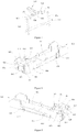
- the present invention provides a module structure, and the module structure comprises a torsional spring 500 that is fixed to a bail 800.
- Fig. 3 shows the perspective view of the assembly wherein the torsional spring is provided on the bail that is provided by the present invention.
- the torsional spring 500 comprises a left torsional spring 501 and a right torsional spring 502 that are symmetrically provided on the bail 800, which are made by bending a linear material that has screw holes.
- Fig. 4 and Fig. 5 respectively show the perspective views of the left torsional spring and the right torsional spring that are provided by the embodiments of the present invention.
- the left torsional spring comprises a first supporting rod 5011, a first screw hole 5013, a first connecting rod 5014 and a second screw hole 5012 that are sequentially connected
- the right torsional spring comprises a second supporting rod 5021, a third screw hole 5023, a second connecting rod 5024 and a fourth screw hole 5022 that are sequentially connected.
- the first supporting rod 5011 and the second supporting rod 5021 are in the form of a straight rod, and the first connecting rod 5014 and the second connecting rod 5024 are in the form of an L-shaped rod.
- the bail 800 is a metal ring that has elasticity, and comprises an upper arm, a lower arm and two sidewalls, and the upper arm comprises a first rotation shaft 801, a third rotation shaft 803, a fourth rotation shaft 804 and a second rotation shaft 802 that are sequentially connected.
- the first rotation shaft 801 and the second rotation shaft 802 are concentric rotation shafts.
- the third rotation shaft 803 and the fourth rotation shaft 804 are concentric rotation shafts, and are provided with a seam 805 therebetween.
- the heights of the third rotation shaft 803 and the fourth rotation shaft 804 are greater than the heights of the first rotation shaft 801 and the second rotation shaft 802, and they are respectively connected to the first rotation shaft 801 and the second rotation shaft 802 by diagonal rods.
- a first side arm 806 and a second side arm 807 are split, the first screw hole 5013 of the left torsional spring 501 is nested outside the first rotation shaft 801, and the second screw hole 5012 is nested outside the third rotation shaft 803 after passing through the L-shaped-rod formed first connecting rod 5014.
- the direction of the first supporting rod 5011 is upwardly inclining and forms an angle of less than 90° with the plane where the bail 800 is located.
- the third screw hole 5023 of the right torsional spring 502 is nested outside the second rotation shaft 802, and the fourth screw hole 5022 is nested outside the fourth rotation shaft 804 after passing through the L-shaped-rod formed second connecting rod 5024.
- the direction of the second supporting rod 5021 is upwardly inclining and forms an angle of less than 90° with the plane where the bail 800 is located.
- Fig. 6 and Fig. 7 show the first perspective view and the second perspective view from two visual angles of the assembly wherein the torsional spring and the brake plate are provided on the bail that is provided by the embodiments of the present invention.
- a brake plate 700 is an elongated structure body that has round holes, and comprises a square brake plate base body, the brake plate base body is connected to sidewalls at the two longer sides, and the sidewalls have concentric round holes in the front.
- the first side arm 806 and the second side arm 807 are split, the third rotation shaft 803 and the fourth rotation shaft 804 are provided in the round holes of the brake plate 700, and, in order to enhance the strength of the bail 800, the seam 805 may be welded after the brake plate 700 is completely assembled.
- the bail 800 When the module structure is being uninstalled from system devices, the bail 800 is pulled, and the bail 800 turns to drive the brake plate 700 and the torsional spring 500 to move toward a spring leaf of a metal shielding cage.
- the first supporting rod 5011 and the second supporting rod 5021 bear a base 600, and the generated torsion force enables the bail to automatically cling to the front end face of the base 600, to enable the bail 800 to automatically reset.
- Fig. 8 and Fig. 9 show the first perspective view and the second perspective view from two visual angles of the base that is provided by the embodiments of the present invention.
- the base 600 is a metal elongated cavity body, and the cavity body 621 contains elements such as a fixture block 200, a detector 410, a laser 420 and a circuit board 430.
- the front end of the cavity body 621 is a two-layer structure.
- a left side and a right side of an upper layer are respectively provided with a first sidewall 609 and a second sidewall 610; an elongated slot 611 whose opening direction is upward and axial direction is the front and back direction is provided between the first sidewall 609 and the second sidewall 610; and a first limiting slot 605 and a second limiting slot 606 that are symmetrical are provided on a lower bottom face of the upper layer, and a first clipping hole 601 and a second clipping hole 602 whose axial directions are the left and right direction are provided on a left side and a right side of the first limiting slot 605 and the second limiting slot 606.
- the first rotation shaft 801 of the bail 800 is placed in the first clipping hole 601, and the second rotation shaft 802 of the bail 800 is placed in the second clipping hole 602; the first limiting slot 605 bears the first supporting rod 5011 of the left torsional spring 501, and the second limiting slot 606 bears the second supporting rod 5021 of the right torsional spring 502; and the brake plate 700 is placed in the elongated slot 611.
- a latch 612 is at the rear of the elongated slot 611; and a first guide slot 603 and a second guide slot 604 whose opening directions are upward are respectively provided behind the first clipping hole 601 and the second clipping hole 602.
- a third depression 613 and a fourth depression 614 that are symmetrical are respectively provided at an upper end and lower end of the sidewall of the base 600 that is adjacent to the front end.
- a fifth depression 615 and a seventh depression 617 are provided behind the third depression 613 and the fourth depression 614 and in the front and back direction of a bottom of a left sidewall of the base 600, and a sixth depression 616 and an eighth depression 618 whose positions respectively correspond to the fifth depression 615 and the seventh depression 617 are provided on a right sidewall.
- a first avoiding slot 619 and a second avoiding slot 620 that are symmetrical are provided on a left rear sidewall and a right rear sidewall of the seventh depression 617 and the eighth depression 618, and the opening directions of the first avoiding slot 619 and the second avoiding slot 620 are upward.
- the embodiments of the module structure that is provided by the present invention further comprise a fixture block 200.
- the fixture block 200 is an elongated structure body that has shielding adhesive, and is provided between the detector 410, the laser 420 and the outer casing 100.
- the shielding adhesive is an elastomer, which results in that the pressures that the detector 410 and the laser 420 bear are elastic force.
- the first embodiment that is provided by the present invention is the first embodiment of the positioning cover that is provided by the present invention.
- Fig. 10 and Fig. 11 respectively show the first perspective view and the second perspective view from two visual angles of the first embodiment of the positioning cover that is provided by the present invention.
- the positioning cover 300 is an irregular metal plate structure body that has inverse clips and a pressure clip, and the positioning cover comprises a square positioning cover base body.
- the positioning cover base body is provided with a third sidewall 301 and a fourth sidewall 302 that extend downwardly from two sides; a fifth inverse clip 306 is provided at a lower horizontal edge of the third sidewall 301, and a sixth inverse clip 307 is provided at a lower horizontal edge of the fourth sidewall 302; a first retaining wall 303 that is perpendicular to the third sidewall 301 is provided at an edge of a front end of the third sidewall 301, and a second retaining wall 304 that is perpendicular to the fourth sidewall 302 is provided at an edge of a front end of the fourth sidewall 302; and a front end of the positioning cover base body extends downwardly to form a screen plate 305, and a rear end extends obliquely downwardly to form a pressure clip 308.
- Fig. 12 shows the exploded view of the combining and assembling between the first embodiment of the positioning cover and the base that is provided by the present invention.
- a first depression 607 and a second depression 608 are respectively provided on lower parts of the first sidewall 609 and the second sidewall 610 at the front end of the base 600 and at the sidewall of the base 600; and the fifth inverse clip 306 is provided in the first depression 607 of the base 600, and the sixth inverse clip 307 is provided in the second depression 608 of the base 600.
- the first retaining wall 303 is provided in the first guide slot 603 of the base 600, for preventing the first rotation shaft 801 of the bail 800 from escaping from the first clipping hole 601 of the base 600
- the second retaining wall 304 is provided in the second guide slot 604 of the base 600, for preventing the second rotation shaft 802 of the bail 800 from escaping from the second clipping hole 602 of the base 600; and the pressure clip 308 presses the brake plate 700 into the elongated slot 611 of the base 600.
- the screen plate 305 forms a closed cavity body with the positioning cover 300 and the base 600 that have been assembled.
- the second embodiment that is provided by the present invention is the second embodiment of the positioning cover that is provided by the present invention.
- Fig. 13 shows the exploded view of the combining and assembling between the second embodiment of the positioning cover and the base that is provided by the present invention
- Fig. 14 shows the perspective view after the completing of the combining and assembling between the second embodiment of the positioning cover and the base that is provided by the present invention.
- the positioning cover base body is provided with a third sidewall 301 and a fourth sidewall 302 that extend downwardly from two sides; a first counterbore 309 and a second counterbore 310 whose axial directions are the left and right direction are respectively provided on the third sidewall 301 and the fourth sidewall 302; a first retaining wall 303 that is perpendicular to the third sidewall 301 is provided at an edge of a front end of the third sidewall 301, and a second retaining wall 304 that is perpendicular to the fourth sidewall 302 is provided at an edge of a front end of the fourth sidewall 302; and a front end of the positioning cover base body extends downwardly to form a screen plate 305, and a rear end extends obliquely downwardly to form a pressure clip 308.
- a first bolt hole 622 and a second bolt hole 623 are respectively provided on the first sidewall 609 and the second sidewall 610 at the front end of the base 600; the first counterbore 309 and the second counterbore 310 respectively correspond to the positions and the sizes of the first bolt hole 622 and the second bolt hole 623, and a first bolt 2000 passes through the first counterbore 309 and the first bolt hole 622, and a second bolt 2001 passes through the second counterbore 310 and the second bolt hole 623, to fix the positioning cover 300 to the base 600.
- the first retaining wall 303 is provided in the first guide slot 603 of the base 600, for preventing the first rotation shaft 801 of the bail 800 from escaping from the first clipping hole 601 of the base 600
- the second retaining wall 304 is provided in the second guide slot 604 of the base 600, for preventing the second rotation shaft 802 of the bail 800 from escaping from the second clipping hole 602 of the base 600
- the pressure clip 308 presses the brake plate 700 onto the base 600
- the screen plate 305 forms a closed cavity body with the positioning cover 300 and the base 600 that have been assembled.
- the third embodiment that is provided by the present invention is the first embodiment of the outer casing that is provided by the present invention.
- Fig. 15 and Fig. 16 respectively show the first perspective view and the second perspective view from two visual angles of the first embodiment of the outer casing that is provided by the present invention.
- the outer casing 100 is an elongated metal plate structure body that comprises a top face 111, a left sidewall and a right sidewall.
- a first inverse clip 101 and a third inverse clip 103 are provided at the lower horizontal edge of the right sidewall of the outer casing
- a second inverse clip 102 and a fourth inverse clip 104 whose positions respectively correspond to the first inverse clip 101 and the third inverse clip 103 are provided at the horizontal edge of the left sidewall
- the inverse clip structures are formed by folding metal plates inwardly, and the number of the inverse clips may be less or more depending on the strength of the structure
- a first elastic presser plate 105 is provided at a vertical edge of the rear end of the right sidewall
- a second elastic presser plate 106 that is symmetrical with the first elastic presser plate 105 is provided at a vertical edge of the rear end of the left sidewall.
- the top face 111 presses the detector 410 and the laser 420 onto the base 600 by pressing the fixture block 200.
- the fourth embodiment that is provided by the present invention is the second embodiment of the outer casing that is provided by the present invention.
- Fig. 17 and Fig. 18 respectively show the first perspective view and the second perspective view from two visual angles of the second embodiment of the outer casing that is provided by the present invention.
- the outer casing 100 is an elongated metal plate structure body that comprises a top face 111, a left sidewall and a right sidewall.
- a first buckle 107 and a third buckle 109 are provided at the lower horizontal edge of the right sidewall of the outer casing, a second buckle 108 and a fourth buckle 110 whose positions respectively correspond to the first buckle 107 and the third buckle 109 are provided at the horizontal edge of the left sidewall, the buckles are protrusion structures that are formed by stamping a metal plate material inwardly, and the number of the buckles may be less or more depending on the strength of the structure; and a first elastic presser plate 105 is provided at a vertical edge of the rear end of the right sidewall, and a second elastic presser plate 106 that is symmetrical with the first elastic presser plate 105 is provided at a vertical edge of the rear end of the left sidewall.
- the top face 111 presses the detector 410 and the laser 420 onto the base 600 by pressing the fixture block 200.
- the fifth embodiment that is provided by the present invention is the first embodiment of the elastic plate that is provided by the present invention.
- Fig. 19 and Fig. 20 respectively show the first perspective view and the second perspective view from two visual angles of the first embodiment of the elastic plate that is provided by the present invention.
- the elastic plate 900 is a metal plate structure body that has an elastic structure, and a seventh inverse clip 901 and an eighth inverse clip 902 are respectively provided at upper horizontal edges of two sidewalls.
- the assembling relations are as follows:
- the elastic plate covers the base 600 from the bottom, the seventh inverse clip 901 is provided in the fourth depression 614 of the base 600, and the eighth inverse clip 902 is provided in the third depression 613 of the base 600, and after the assembling the elastic plate 900 completely covers the third depression 613 and the fourth depression 614 on the side of the base 600, which avoids the problem of the prior art of the exposing of the appearance of the base material that is caused by the scraping to the base during the assembling of the elastic plate 3300.
- the sixth embodiment that is provided by the present invention is the second embodiment of the elastic plate that is provided by the present invention.
- Fig. 21 and Fig. 22 respectively show the first perspective view and the second perspective view from two visual angles of the second embodiment of the elastic plate that is provided by the present invention.
- the elastic plate 900 is a metal plate structure body that has an elastic structure
- a fifth buckle 903 and a sixth buckle 904 are respectively provided on the two sidewalls of the elastic plate 900
- the fifth buckle 903 of the right sidewall and the sixth buckle 904 of the left sidewall are protrusion structures that are formed by stamping a metal plate material inwardly.
- the assembling relations are as follows:
- the elastic plate covers the base 600 from the bottom, the fifth buckle 903 is provided in the third depression 614 of the base 600, and the sixth buckle 904 is provided in the fourth depression 613 of the base 600, and after the assembling the elastic plate 900 completely covers the third depression 613 and the fourth depression 614 on the side of the base 600, which avoids the problem of the prior art of the exposing of the appearance of the base material that is caused by the scraping to the base during the assembling of the elastic plate 3300.
- the installing steps of the installing and uninstalling device for a module structure that is provided by the present invention comprise:
- the installing steps of the module structure that is provided by the present invention comprise:
- Fig. 23 shows the perspective view after the installing is completed of the module structure that is provided by the embodiments of the present invention.
Landscapes
- Physics & Mathematics (AREA)
- General Physics & Mathematics (AREA)
- Optics & Photonics (AREA)
- Engineering & Computer Science (AREA)
- Microelectronics & Electronic Packaging (AREA)
- Electromagnetism (AREA)
- Casings For Electric Apparatus (AREA)
- Connection Of Plates (AREA)
Claims (10)
- Optisch-elektrische Modulstruktur, wobei die optisch-elektrische Modulstruktur eine Verdrehungsfeder (500) umfasst, die an einem Bügel (800) befestigt ist;
wobei die Verdrehungsfeder (500) eine linke Verdrehungsfeder (501) und eine rechte Verdrehungsfeder (502) umfasst, die auf dem Bügel (800) symmetrisch bereitgestellt sind;
dadurch gekennzeichnet, dass die linke Verdrehungsfeder eine erste Stützstange (5011), ein erstes Schraubenloch (5013), eine erste Verbindungsstange (5014) und ein zweites Schraubenloch (5012) umfasst, die aufeinanderfolgend verbunden sind; und
die rechte Verdrehungsfeder eine zweite Stützstange (5021), ein drittes Schraubenloch (5023), eine zweite Verbindungsstange (5024) und ein viertes Schraubenloch (5022) umfasst, die aufeinanderfolgend verbunden sind; und
die Schraubenlöcher (5013, 5012, 5023, 5022) durch Aufwickeln der Feder zum Aufnehmen des Bügels (800) gebildet sind;
die erste Stützstange (5011) und die zweite Stützstange (5021) in der Form einer geraden Stange sind, und die erste Verbindungsstange (5014) und die zweite Verbindungsstange (5024) in der Form einer L-förmigen Stange sind;
das zweite Schraubenloch (5012) außerhalb einer dritten Rotationswelle (803) des Bügels (800) verschachtelt ist, wobei das erste Schraubenloch (5013) außerhalb einer ersten Rotationswelle (801) verschachtelt ist, nachdem es durch die erste Verbindungsstange (5014) geführt ist, und eine Richtung der ersten Stützstange (5011) nach oben geneigt ist und einen Winkel von weniger als 90° mit der Ebene ausbildet, in der sich der Bügel (800) befindet; und
das vierte Schraubenloch (5022) außerhalb einer vierten Rotationswelle (804) des Bügels (800) verschachtelt ist, wobei das dritte Schraubenloch (5023) außerhalb einer zweiten Rotationswelle (802) verschachtelt ist, nachdem es durch die zweite Verbindungsstange (5024) geführt ist, und eine Richtung der zweiten Stützstange (5021) nach oben geneigt ist und einen Winkel von weniger als 90° mit der Ebene ausbildet, in der sich der Bügel (800) befindet; und
der Bügel (800) die erste Rotationswelle (801), die dritte Rotationswelle (803), die vierte Rotationswelle (804) und die zweite Rotationswelle (802) umfasst, die aufeinanderfolgend verbunden sind;
wobei die erste Rotationswelle (801) und die zweite Rotationswelle (802) konzentrische Rotationswellen sind;
die dritte Rotationswelle (803) und die vierte Rotationswelle (804) konzentrische Rotationswellen sind und mit einer Naht (805) dazwischen versehen sind, wobei die Höhen der dritten Rotationswelle (803) und der vierten Rotationswelle (804) über den Höhen der ersten Rotationswelle (801) und der zweiten Rotationswelle (802) liegen, und sie jeweils mit der ersten Rotationswelle (801) und der zweiten Rotationswelle (802) durch Diagonalstangen verbunden sind. - Optisch-elektrische Modulstruktur nach Anspruch 1, dadurch gekennzeichnet, dass die optisch-elektrische Modulstruktur ferner eine Basis (600) umfasst;
wobei die Basis (600) ein länglicher Metallhohlraumkörper ist, und ein vorderes Ende des Hohlraumkörpers (621) eine zweischichtige Struktur ist;
eine linke Seite und eine rechte Seite einer oberen Schicht jeweils mit einer ersten Seitenwand (609) und einer zweiten Seitenwand (610) versehen sind;
ein länglicher Schlitz (611), dessen Öffnungsrichtung nach oben ist und dessen axiale Richtung die vordere und die hintere Richtung ist, zwischen der ersten Seitenwand (609) und der zweiten Seitenwand (610) bereitgestellt ist; und
eine Bremsplatte (700) in dem länglichen Schlitz (611) platziert ist;
ein erster Begrenzungsschlitz (605) und ein zweiter Begrenzungsschlitz (606) auf einer unteren Bodenfläche der oberen Schicht symmetrisch bereitgestellt sind; und
der erste Begrenzungsschlitz (605) die erste Stützstange (5011) der linken Verdrehungsfeder (501) trägt, und der zweite Begrenzungsschlitz (606) die zweite Stützstange (5021) der rechten Verdrehungsfeder (502) trägt;
ein erstes Klemmloch (601) und ein zweites Klemmloch (602), deren axiale Richtungen die linke und die rechte Richtung sind, auf einer linken Seite und einer rechten Seite des ersten Begrenzungsschlitzes (605) und des zweiten Begrenzungsschlitzes (606) bereitgestellt sind; und
die erste Rotationswelle (801) des Bügels (800) in dem ersten Klemmloch (601) platziert ist, und die zweite Rotationswelle (802) des Bügels (800) in dem zweiten Klemmloch (602) platziert ist;
ein erster Führungsschlitz (603) und ein zweiter Führungsschlitz (604), deren Öffnungsrichtungen nach oben sind, jeweils hinter dem ersten Klemmloch (601) und dem zweiten Klemmloch (602) bereitgestellt sind;
eine dritte Vertiefung (613) und eine vierte Vertiefung (614) an den unteren Abschnitten der Seitenwände der Basis (600), die an das vordere Ende angrenzend ist, symmetrisch bereitgestellt sind;
die dritte Vertiefung (613) in dem unteren Abschnitt einer linken Seitenwand der Basis (600) bereitgestellt ist, die vierte Vertiefung (614) in dem unteren Teil einer rechten Seitenwand der Basis (600) bereitgestellt ist und die Position der vierten Vertiefung (614) der dritten Vertiefung (613) entspricht;
eine fünfte Vertiefung (615) und eine siebte Vertiefung (617) hinter der dritten Vertiefung (613) und in Vorder- und Rückrichtung eines Bodens der linken Seitenwand der Basis (600) bereitgestellt sind, und eine sechste Vertiefung (616) und eine achte Vertiefung (618), deren Positionen jeweils der fünften Vertiefung (615) und der siebten Vertiefung (617) entsprechen, an der rechten Seitenwand der Basis (600) bereitgestellt sind; und
ein erster Ausweichschlitz (619) und ein zweiter Ausweichschlitz (620) symmetrisch an den Seitenwänden der Basis (600) bereitgestellt sind;
wobei der erste Ausweichschlitz (619) an der linken Seitenwand der Basis (600) und hinter der siebten Vertiefung (617) bereitgestellt ist, und der zweite Ausweichschlitz (620) an der rechten Seitenwand der Basis (600) und hinter der achten Vertiefung (618) bereitgestellt ist, und die Öffnungsrichtungen des ersten Ausweichschlitzes (619) und des zweiten Ausweichschlitzes (620) nach oben sind. - Optisch-elektrische Modulstruktur nach Anspruch 2, dadurch gekennzeichnet, dass die optisch-elektrische Modulstruktur ferner eine Positionierabdeckung (300) umfasst;
wobei die Positionierabdeckung (300) einen quadratischen Positionierungsabdeckungsbasiskörper umfasst;
der Positionierungsabdeckungsbasiskörper mit einer dritten Seitenwand (301) und einer vierten Seitenwand (302) versehen ist, die sich von zwei Seiten nach unten erstrecken;
eine erste Haltewand (303), die senkrecht zu der dritten Seitenwand (301) ist, an einer Kante eines vorderen Endes der dritten Seitenwand (301) bereitgestellt ist, und eine zweite Haltewand (304), die senkrecht zu der vierten Seitenwand (302) ist, an einer Kante eines vorderen Endes der vierten Seitenwand (302) bereitgestellt ist;
wobei ein vorderes Ende des Positionierungsabdeckungsbasiskörpers sich nach unten erstreckt, um eine Siebplatte (305) auszubilden, und ein hinteres Ende sich schräg nach unten erstreckt, um eine Druckklemme (308) auszubilden;
die dritte Seitenwand (301) an der ersten Seitenwand (609) der Basis (600) haftet und die vierte Seitenwand (302) an der zweiten Seitenwand (610) der Basis (600) haftet;
die erste Haltewand (303) in dem ersten Führungsschlitz (603) der Basis (600) bereitgestellt ist, und die zweite Haltewand (304) in dem zweiten Führungsschlitz (604) der Basis (600) bereitgestellt ist;
wobei die Druckklemme (308) die Bremsplatte (700) in den länglichen Schlitz (611) der Basis (600) drückt; und
die Siebplatte (305) einen geschlossenen Hohlraumraumkörper mit der Positionierungsabdeckung (300) und der Basis (600), die zusammengebaut wurden, ausbildet. - Optisch-elektrische Modulstruktur nach Anspruch 3, dadurch gekennzeichnet, dass eine fünfte inverse Klemme (306) an einer unteren horizontalen Kante der dritten Seitenwand (301) des Positionierungsabdeckungsbasiskörpers und eine sechste inverse Klemme (307) an einer unteren horizontalen Kante der vierten Seitenwand (302) des Positionierungsabdeckungsbasiskörpers bereitgestellt ist;
eine erste Vertiefung (607) und eine zweite Vertiefung (608) jeweils an den unteren Teilen der ersten Seitenwand (609) und der zweiten Seitenwand (610) an dem vorderen Ende der Basis (600) und an der Seitenwand der Basis (600) bereitgestellt sind; und
die fünfte inverse Klemme (306) in der ersten Vertiefung (607) der Basis (600) bereitgestellt ist, und die sechste inverse Klemme (307) in der zweiten Vertiefung (608) der Basis (600) bereitgestellt ist, um die Positionierungsabdeckung (300) an der Basis (600) zu fixieren. - Optisch-elektrische Modulstruktur nach Anspruch 3, dadurch gekennzeichnet, dass eine erste Senkung (309) und eine zweite Senkung (310), deren axiale Richtungen die linke und die rechte Richtung sind, jeweils an der dritten Seitenwand (301) und der vierten Seitenwand (302) des Positionierungsabdeckungsbasiskörpers bereitgestellt sind;
ein erstes Bolzenloch (622) und ein zweites Bolzenloch (623) jeweils an der ersten Seitenwand (609) und der zweiten Seitenwand (610) der Basis (600) an dem vorderen Ende der Basis (600) bereitgestellt sind; und
die erste Senkung (309) und die zweite Senkung (310) jeweils Positionen und Größen des ersten Bolzenlochs (622) und des zweiten Bolzenlochs (623) entsprechen, und ein erster Bolzen (2000) durch die erste Senkung (309) und das erste Bolzenloch (622) führt, und ein zweiter Bolzen (2001) durch die zweite Senkung (310) und das zweite Bolzenloch (623) führt, um die Positionierungsabdeckung (300) an der Basis (600) zu befestigen. - Optisch-elektrische Modulstruktur nach Anspruch 2, dadurch gekennzeichnet, dass die optisch-elektrische Modulstruktur ferner ein Außengehäuse (100) umfasst;
wobei das Außengehäuse (100) ein länglicher Metallplattenstrukturkörper ist, der eine Oberfläche (111), eine linke Seitenwand und eine rechte Seitenwand umfasst, und die Basis (600) bedeckt;
eine erste elastische Druckplatte (105) an einer vertikalen Kante des hinteren Endes der rechten Seitenwand des Außengehäuses (100) bereitgestellt ist, und eine zweite elastische Druckplatte (106), die zu der ersten elastischen Druckplatte (105) symmetrisch ist, an einer vertikalen Kante des hinteren Endes der linken Seitenwand des Außengehäuses (100) bereitgestellt ist. - Optisch-elektrische Modulstruktur nach Anspruch 6, dadurch gekennzeichnet, dass eine erste inverse Klemme (101) und eine dritte inverse Klemme (103) an der unteren horizontalen Kante der rechten Seitenwand des Außengehäuses (100) bereitgestellt sind und eine zweite inverse Klemme (102) und eine vierte inverse Klemme (104), deren Positionen jeweils der ersten inversen Klemme (101) und der dritten inversen Klemme (103) entsprechen, an der horizontalen Kante der linken Seitenwand des Außengehäuses (100) bereitgestellt sind;
wobei die inversen Klemmstrukturen durch Falten von Metallplatten nach innen ausgebildet sind; und
die erste inverse Klemme (101) in der sechsten Vertiefung (616) der Basis (600) bereitgestellt ist, die zweite inverse Klemme (102) in der fünften Vertiefung (615) der Basis (600) bereitgestellt ist, die dritte inverse Klemme (103) in der achten Vertiefung (618) der Basis (600) bereitgestellt ist, und die vierte inverse Klemme (104) in der siebten Vertiefung (617) der Basis (600) bereitgestellt ist, um das Außengehäuse (100) der Basis (600) zusammenzubauen. - Optisch-elektrische Modulstruktur nach Anspruch 6, dadurch gekennzeichnet, dass eine erste Schnalle (107) und eine dritte Schnalle (109) an der unteren horizontalen Kante der rechten Seitenwand des Außengehäuses (100) bereitgestellt sind und eine zweite Schnalle (108) und eine vierte Schnalle (110), deren Positionen jeweils der ersten Schnalle (107) und der dritten Schnalle (109) entsprechen, an der horizontalen Kante der linken Seitenwand des Außengehäuses (100) bereitgestellt sind;
wobei die Schnallen Vorsprungsstrukturen sind, die durch Stanzen eines Metallplattenmaterials nach innen ausgebildet sind; und
die erste Schnalle (107) in der sechsten Vertiefung (616) der Basis (600) bereitgestellt ist, die zweite Schnalle (108) in der fünften Vertiefung (615) der Basis (600) bereitgestellt ist, die dritte Schnalle (109) in der achten Vertiefung (618) der Basis (600) bereitgestellt ist, und die vierte Schnalle (110) in der siebten Vertiefung (617) der Basis (600) bereitgestellt ist, um das Außengehäuse (100) auf der Basis (600) zusammenzubauen. - Optisch-elektrische Modulstruktur nach Anspruch 2, dadurch gekennzeichnet, dass die optisch-elektrische Modulstruktur ferner eine elastische Platte (900) umfasst;
wobei die elastische Platte (900) ein Metallplattenstrukturkörper ist, der eine elastische Struktur aufweist, und wobei eine siebte inverse Klemme (901) und eine achte inverse Klemme (902) jeweils an den oberen horizontalen Kanten von zwei Seitenwänden bereitgestellt sind; und
die elastische Platte (900) die Basis (600) von unten bedeckt, wobei die siebte inverse Klemme (901) in der vierten Vertiefung (614) der Basis (600) bereitgestellt ist, und die achte inverse Klemme (902) in der dritten Vertiefung (613) der Basis (600) bereitgestellt ist. - Optisch-elektrische Modulstruktur nach Anspruch 2, dadurch gekennzeichnet, dass die optisch-elektrische Modulstruktur ferner eine elastische Platte (900) umfasst;
wobei eine fünfte Schnalle (903) und eine sechste Schnalle (904) jeweils an den beiden Seitenwänden der elastischen Platte (900) bereitgestellt sind, und die fünfte Schnalle (903) der rechten Seitenwand und die sechste Schnalle (904) der rechten Seitenwand Vorsprungsstrukturen sind, die durch Stanzen eines Metallplattenmaterials nach innen ausgebildet sind;
wobei die fünfte Schnalle (903) in der dritten Vertiefung (613) der Basis (600) bereitgestellt ist, und die sechste Schnalle (904) in der vierten Vertiefung (614) der Basis (600) bereitgestellt ist.
Applications Claiming Priority (2)
| Application Number | Priority Date | Filing Date | Title |
|---|---|---|---|
| CN201510291772.XA CN104865652B (zh) | 2015-06-01 | 2015-06-01 | 一种模块结构 |
| PCT/CN2015/089299 WO2016192234A1 (zh) | 2015-06-01 | 2015-09-10 | 一种模块结构 |
Publications (3)
| Publication Number | Publication Date |
|---|---|
| EP3290976A1 EP3290976A1 (de) | 2018-03-07 |
| EP3290976A4 EP3290976A4 (de) | 2018-07-11 |
| EP3290976B1 true EP3290976B1 (de) | 2020-10-21 |
Family
ID=53911605
Family Applications (1)
| Application Number | Title | Priority Date | Filing Date |
|---|---|---|---|
| EP15893890.2A Active EP3290976B1 (de) | 2015-06-01 | 2015-09-10 | Modulstruktur |
Country Status (4)
| Country | Link |
|---|---|
| US (1) | US10094991B2 (de) |
| EP (1) | EP3290976B1 (de) |
| CN (1) | CN104865652B (de) |
| WO (1) | WO2016192234A1 (de) |
Families Citing this family (11)
| Publication number | Priority date | Publication date | Assignee | Title |
|---|---|---|---|---|
| CN104865652B (zh) | 2015-06-01 | 2016-08-10 | 武汉电信器件有限公司 | 一种模块结构 |
| CN105954839B (zh) * | 2016-06-28 | 2018-09-28 | 武汉电信器件有限公司 | 一种模块的安装卸载装置及其安装方法 |
| DE102016116926A1 (de) * | 2016-09-09 | 2018-03-15 | Harting Electric Gmbh & Co. Kg | Überspannungsschutzmodul für einen modularen Steckverbinder |
| CN106772831B (zh) * | 2016-11-29 | 2018-09-04 | 武汉电信器件有限公司 | 一种自沉式解锁的光模块及其外壳结构 |
| CN109991704A (zh) * | 2018-01-02 | 2019-07-09 | 台达电子工业股份有限公司 | 光收发模块 |
| CN111224293B (zh) * | 2018-11-23 | 2021-05-14 | 陕西重型汽车有限公司 | 基于车辆非金属接插件的屏蔽保护罩 |
| CN109633836B (zh) * | 2019-01-30 | 2019-11-15 | 深圳市亚派光电器件有限公司 | 拉环及光模块 |
| CN114730053A (zh) * | 2019-12-31 | 2022-07-08 | 华为技术有限公司 | 光模块解锁装置、光模块及光通信设备 |
| CN112346182B (zh) * | 2020-12-10 | 2021-07-06 | 武汉电信器件有限公司 | 一种光模块 |
| CN113325525B (zh) * | 2021-04-09 | 2023-03-10 | 武汉华工正源光子技术有限公司 | 盒体组件及光模块 |
| US12339505B2 (en) * | 2022-09-29 | 2025-06-24 | Pinjack International Llc | Pluggable transceiver module |
Family Cites Families (19)
| Publication number | Priority date | Publication date | Assignee | Title |
|---|---|---|---|---|
| TW343739U (en) * | 1997-09-13 | 1998-10-21 | Transian Technology Co Ltd | An optic adapter with protection feature |
| US6830385B2 (en) * | 2002-09-30 | 2004-12-14 | Hitachi Cable, Ltd. | Package having lock mechanism |
| CN2738478Y (zh) * | 2004-11-11 | 2005-11-02 | 深圳飞通光电股份有限公司 | Sfp光收发一体模块 |
| TWI300859B (en) * | 2005-06-29 | 2008-09-11 | Axcen Photonics Corp | Dustproof and pluggable transceiver |
| CN200966056Y (zh) * | 2006-06-29 | 2007-10-24 | 武汉电信器件有限公司 | 简约式光电模块拉环解锁装置 |
| CN200962597Y (zh) * | 2006-08-30 | 2007-10-17 | 武汉电信器件有限公司 | 热插拔光电模块拉环式解锁复位装置 |
| CN201114062Y (zh) * | 2007-08-13 | 2008-09-10 | 宝得粉末注射成形(常熟)有限公司 | 光电模块用拉环式解锁装置 |
| CN201207501Y (zh) * | 2008-04-30 | 2009-03-11 | 富士康(昆山)电脑接插件有限公司 | 连接器模组 |
| JP2009277410A (ja) | 2008-05-13 | 2009-11-26 | Molex Inc | コネクタ |
| CN101614850A (zh) * | 2009-07-21 | 2009-12-30 | 武汉电信器件有限公司 | 一种光电模块拉环式解锁装置 |
| CN201749224U (zh) * | 2010-03-25 | 2011-02-16 | 武汉蓝丹科技有限公司 | Sfp光收发模块解扣机构 |
| CN102183826B (zh) * | 2011-05-03 | 2012-10-17 | 武汉电信器件有限公司 | 一种模块、用于模块的安装卸载装置 |
| CN203519884U (zh) | 2013-09-23 | 2014-04-02 | 无锡市恒英盛电子科技有限公司 | 一种小型可热插拔光收发一体模块的解锁机构 |
| CN104345414B (zh) * | 2014-10-31 | 2016-08-31 | 武汉电信器件有限公司 | 模块回退式安装卸载装置 |
| CN204441611U (zh) * | 2015-01-23 | 2015-07-01 | 昆山合真和光电科技有限公司 | 具有锁扣与解锁机构的小型可插拔连接器 |
| CN104617445B (zh) | 2015-01-23 | 2017-02-01 | 昆山合真和光电科技有限公司 | 具有锁扣与解锁机构的小型可插拔连接器 |
| CN104614821B (zh) * | 2015-02-14 | 2016-05-04 | 深圳市摩泰光电有限公司 | 压合式解锁装置及其rj45电口sfp模块 |
| CN104865652B (zh) | 2015-06-01 | 2016-08-10 | 武汉电信器件有限公司 | 一种模块结构 |
| CN204666873U (zh) * | 2015-06-01 | 2015-09-23 | 武汉电信器件有限公司 | 一种模块结构 |
-
2015
- 2015-06-01 CN CN201510291772.XA patent/CN104865652B/zh active Active
- 2015-09-10 EP EP15893890.2A patent/EP3290976B1/de active Active
- 2015-09-10 US US15/576,855 patent/US10094991B2/en active Active
- 2015-09-10 WO PCT/CN2015/089299 patent/WO2016192234A1/zh not_active Ceased
Non-Patent Citations (1)
| Title |
|---|
| None * |
Also Published As
| Publication number | Publication date |
|---|---|
| US20180172927A1 (en) | 2018-06-21 |
| EP3290976A1 (de) | 2018-03-07 |
| US10094991B2 (en) | 2018-10-09 |
| EP3290976A4 (de) | 2018-07-11 |
| CN104865652B (zh) | 2016-08-10 |
| WO2016192234A1 (zh) | 2016-12-08 |
| CN104865652A (zh) | 2015-08-26 |
Similar Documents
| Publication | Publication Date | Title |
|---|---|---|
| EP3290976B1 (de) | Modulstruktur | |
| KR101986914B1 (ko) | 휴대용 기기의 액세서리 | |
| US9954316B2 (en) | Module retracting type installing and uninstalling device | |
| KR102382008B1 (ko) | 쉴드 커버 및 그것을 포함하는 전자 장치 | |
| US20120170188A1 (en) | Enclosure of electronic device | |
| KR20180102578A (ko) | 멀티 피스 실드 | |
| US8247707B2 (en) | Shielding assembly | |
| CN108633163A (zh) | 用于电子装置的电路板的避震结构及其电子装置 | |
| US20130279132A1 (en) | Electromagnetic shielding cover | |
| CN108628019A (zh) | 罩安装结构以及显示装置 | |
| TWI492700B (zh) | 壁掛機構 | |
| US9638231B2 (en) | Detachable fixing mechanism and related electronic device | |
| EP2802196A3 (de) | Strahlungsschirmabstand | |
| US20110273067A1 (en) | Enclosure of electronic device with groove | |
| US20120181736A1 (en) | Mounting apparatus for electronic devices | |
| TW201318506A (zh) | 機櫃及固線裝置 | |
| US8936327B2 (en) | Bezel assembly for electronic device | |
| KR102241809B1 (ko) | 디스플레이 장치 및 프레임 부재 | |
| US9007749B2 (en) | Electronic device enclosure | |
| TWM450180U (zh) | 電子裝置殼體 | |
| US7667985B1 (en) | Computer network device and method of assembly | |
| TW201349673A (zh) | 連接器 | |
| JP6115376B2 (ja) | パネル固定構造、及び自動取引装置 | |
| KR101109597B1 (ko) | 디지털 기기용 삼각대 어댑터 및 이를 구비한 삼각대 | |
| CN204517004U (zh) | 转接器 |
Legal Events
| Date | Code | Title | Description |
|---|---|---|---|
| STAA | Information on the status of an ep patent application or granted ep patent |
Free format text: STATUS: THE INTERNATIONAL PUBLICATION HAS BEEN MADE |
|
| PUAI | Public reference made under article 153(3) epc to a published international application that has entered the european phase |
Free format text: ORIGINAL CODE: 0009012 |
|
| STAA | Information on the status of an ep patent application or granted ep patent |
Free format text: STATUS: REQUEST FOR EXAMINATION WAS MADE |
|
| 17P | Request for examination filed |
Effective date: 20171201 |
|
| AK | Designated contracting states |
Kind code of ref document: A1 Designated state(s): AL AT BE BG CH CY CZ DE DK EE ES FI FR GB GR HR HU IE IS IT LI LT LU LV MC MK MT NL NO PL PT RO RS SE SI SK SM TR |
|
| AX | Request for extension of the european patent |
Extension state: BA ME |
|
| A4 | Supplementary search report drawn up and despatched |
Effective date: 20180608 |
|
| RIC1 | Information provided on ipc code assigned before grant |
Ipc: G02B 6/42 20060101AFI20180601BHEP Ipc: H01R 13/633 20060101ALI20180601BHEP |
|
| DAV | Request for validation of the european patent (deleted) | ||
| DAX | Request for extension of the european patent (deleted) | ||
| GRAP | Despatch of communication of intention to grant a patent |
Free format text: ORIGINAL CODE: EPIDOSNIGR1 |
|
| STAA | Information on the status of an ep patent application or granted ep patent |
Free format text: STATUS: GRANT OF PATENT IS INTENDED |
|
| RIC1 | Information provided on ipc code assigned before grant |
Ipc: G02B 6/42 20060101AFI20200408BHEP Ipc: H01R 13/6583 20110101ALI20200408BHEP |
|
| INTG | Intention to grant announced |
Effective date: 20200428 |
|
| RIN1 | Information on inventor provided before grant (corrected) |
Inventor name: SONG, BEILI Inventor name: QUAN, BENQING Inventor name: JIANG, YI Inventor name: GAO, FANRONG |
|
| GRAS | Grant fee paid |
Free format text: ORIGINAL CODE: EPIDOSNIGR3 |
|
| GRAA | (expected) grant |
Free format text: ORIGINAL CODE: 0009210 |
|
| STAA | Information on the status of an ep patent application or granted ep patent |
Free format text: STATUS: THE PATENT HAS BEEN GRANTED |
|
| AK | Designated contracting states |
Kind code of ref document: B1 Designated state(s): AL AT BE BG CH CY CZ DE DK EE ES FI FR GB GR HR HU IE IS IT LI LT LU LV MC MK MT NL NO PL PT RO RS SE SI SK SM TR |
|
| REG | Reference to a national code |
Ref country code: GB Ref legal event code: FG4D |
|
| REG | Reference to a national code |
Ref country code: CH Ref legal event code: EP |
|
| REG | Reference to a national code |
Ref country code: IE Ref legal event code: FG4D |
|
| REG | Reference to a national code |
Ref country code: DE Ref legal event code: R096 Ref document number: 602015060973 Country of ref document: DE |
|
| REG | Reference to a national code |
Ref country code: AT Ref legal event code: REF Ref document number: 1326384 Country of ref document: AT Kind code of ref document: T Effective date: 20201115 |
|
| REG | Reference to a national code |
Ref country code: SE Ref legal event code: TRGR |
|
| REG | Reference to a national code |
Ref country code: AT Ref legal event code: MK05 Ref document number: 1326384 Country of ref document: AT Kind code of ref document: T Effective date: 20201021 |
|
| REG | Reference to a national code |
Ref country code: NL Ref legal event code: MP Effective date: 20201021 |
|
| PG25 | Lapsed in a contracting state [announced via postgrant information from national office to epo] |
Ref country code: RS Free format text: LAPSE BECAUSE OF FAILURE TO SUBMIT A TRANSLATION OF THE DESCRIPTION OR TO PAY THE FEE WITHIN THE PRESCRIBED TIME-LIMIT Effective date: 20201021 Ref country code: PT Free format text: LAPSE BECAUSE OF FAILURE TO SUBMIT A TRANSLATION OF THE DESCRIPTION OR TO PAY THE FEE WITHIN THE PRESCRIBED TIME-LIMIT Effective date: 20210222 Ref country code: FI Free format text: LAPSE BECAUSE OF FAILURE TO SUBMIT A TRANSLATION OF THE DESCRIPTION OR TO PAY THE FEE WITHIN THE PRESCRIBED TIME-LIMIT Effective date: 20201021 Ref country code: NL Free format text: LAPSE BECAUSE OF FAILURE TO SUBMIT A TRANSLATION OF THE DESCRIPTION OR TO PAY THE FEE WITHIN THE PRESCRIBED TIME-LIMIT Effective date: 20201021 Ref country code: NO Free format text: LAPSE BECAUSE OF FAILURE TO SUBMIT A TRANSLATION OF THE DESCRIPTION OR TO PAY THE FEE WITHIN THE PRESCRIBED TIME-LIMIT Effective date: 20210121 Ref country code: GR Free format text: LAPSE BECAUSE OF FAILURE TO SUBMIT A TRANSLATION OF THE DESCRIPTION OR TO PAY THE FEE WITHIN THE PRESCRIBED TIME-LIMIT Effective date: 20210122 |
|
| REG | Reference to a national code |
Ref country code: LT Ref legal event code: MG4D |
|
| PG25 | Lapsed in a contracting state [announced via postgrant information from national office to epo] |
Ref country code: AT Free format text: LAPSE BECAUSE OF FAILURE TO SUBMIT A TRANSLATION OF THE DESCRIPTION OR TO PAY THE FEE WITHIN THE PRESCRIBED TIME-LIMIT Effective date: 20201021 Ref country code: ES Free format text: LAPSE BECAUSE OF FAILURE TO SUBMIT A TRANSLATION OF THE DESCRIPTION OR TO PAY THE FEE WITHIN THE PRESCRIBED TIME-LIMIT Effective date: 20201021 Ref country code: LV Free format text: LAPSE BECAUSE OF FAILURE TO SUBMIT A TRANSLATION OF THE DESCRIPTION OR TO PAY THE FEE WITHIN THE PRESCRIBED TIME-LIMIT Effective date: 20201021 Ref country code: IS Free format text: LAPSE BECAUSE OF FAILURE TO SUBMIT A TRANSLATION OF THE DESCRIPTION OR TO PAY THE FEE WITHIN THE PRESCRIBED TIME-LIMIT Effective date: 20210221 Ref country code: PL Free format text: LAPSE BECAUSE OF FAILURE TO SUBMIT A TRANSLATION OF THE DESCRIPTION OR TO PAY THE FEE WITHIN THE PRESCRIBED TIME-LIMIT Effective date: 20201021 Ref country code: BG Free format text: LAPSE BECAUSE OF FAILURE TO SUBMIT A TRANSLATION OF THE DESCRIPTION OR TO PAY THE FEE WITHIN THE PRESCRIBED TIME-LIMIT Effective date: 20210121 |
|
| PG25 | Lapsed in a contracting state [announced via postgrant information from national office to epo] |
Ref country code: HR Free format text: LAPSE BECAUSE OF FAILURE TO SUBMIT A TRANSLATION OF THE DESCRIPTION OR TO PAY THE FEE WITHIN THE PRESCRIBED TIME-LIMIT Effective date: 20201021 |
|
| REG | Reference to a national code |
Ref country code: DE Ref legal event code: R097 Ref document number: 602015060973 Country of ref document: DE |
|
| PG25 | Lapsed in a contracting state [announced via postgrant information from national office to epo] |
Ref country code: LT Free format text: LAPSE BECAUSE OF FAILURE TO SUBMIT A TRANSLATION OF THE DESCRIPTION OR TO PAY THE FEE WITHIN THE PRESCRIBED TIME-LIMIT Effective date: 20201021 Ref country code: SM Free format text: LAPSE BECAUSE OF FAILURE TO SUBMIT A TRANSLATION OF THE DESCRIPTION OR TO PAY THE FEE WITHIN THE PRESCRIBED TIME-LIMIT Effective date: 20201021 Ref country code: EE Free format text: LAPSE BECAUSE OF FAILURE TO SUBMIT A TRANSLATION OF THE DESCRIPTION OR TO PAY THE FEE WITHIN THE PRESCRIBED TIME-LIMIT Effective date: 20201021 Ref country code: CZ Free format text: LAPSE BECAUSE OF FAILURE TO SUBMIT A TRANSLATION OF THE DESCRIPTION OR TO PAY THE FEE WITHIN THE PRESCRIBED TIME-LIMIT Effective date: 20201021 Ref country code: RO Free format text: LAPSE BECAUSE OF FAILURE TO SUBMIT A TRANSLATION OF THE DESCRIPTION OR TO PAY THE FEE WITHIN THE PRESCRIBED TIME-LIMIT Effective date: 20201021 Ref country code: SK Free format text: LAPSE BECAUSE OF FAILURE TO SUBMIT A TRANSLATION OF THE DESCRIPTION OR TO PAY THE FEE WITHIN THE PRESCRIBED TIME-LIMIT Effective date: 20201021 |
|
| PLBE | No opposition filed within time limit |
Free format text: ORIGINAL CODE: 0009261 |
|
| STAA | Information on the status of an ep patent application or granted ep patent |
Free format text: STATUS: NO OPPOSITION FILED WITHIN TIME LIMIT |
|
| PG25 | Lapsed in a contracting state [announced via postgrant information from national office to epo] |
Ref country code: DK Free format text: LAPSE BECAUSE OF FAILURE TO SUBMIT A TRANSLATION OF THE DESCRIPTION OR TO PAY THE FEE WITHIN THE PRESCRIBED TIME-LIMIT Effective date: 20201021 |
|
| 26N | No opposition filed |
Effective date: 20210722 |
|
| PG25 | Lapsed in a contracting state [announced via postgrant information from national office to epo] |
Ref country code: AL Free format text: LAPSE BECAUSE OF FAILURE TO SUBMIT A TRANSLATION OF THE DESCRIPTION OR TO PAY THE FEE WITHIN THE PRESCRIBED TIME-LIMIT Effective date: 20201021 |
|
| PG25 | Lapsed in a contracting state [announced via postgrant information from national office to epo] |
Ref country code: SI Free format text: LAPSE BECAUSE OF FAILURE TO SUBMIT A TRANSLATION OF THE DESCRIPTION OR TO PAY THE FEE WITHIN THE PRESCRIBED TIME-LIMIT Effective date: 20201021 |
|
| REG | Reference to a national code |
Ref country code: CH Ref legal event code: PL |
|
| REG | Reference to a national code |
Ref country code: BE Ref legal event code: MM Effective date: 20210930 |
|
| GBPC | Gb: european patent ceased through non-payment of renewal fee |
Effective date: 20210910 |
|
| PG25 | Lapsed in a contracting state [announced via postgrant information from national office to epo] |
Ref country code: IS Free format text: LAPSE BECAUSE OF FAILURE TO SUBMIT A TRANSLATION OF THE DESCRIPTION OR TO PAY THE FEE WITHIN THE PRESCRIBED TIME-LIMIT Effective date: 20210221 Ref country code: MC Free format text: LAPSE BECAUSE OF FAILURE TO SUBMIT A TRANSLATION OF THE DESCRIPTION OR TO PAY THE FEE WITHIN THE PRESCRIBED TIME-LIMIT Effective date: 20201021 |
|
| PG25 | Lapsed in a contracting state [announced via postgrant information from national office to epo] |
Ref country code: LU Free format text: LAPSE BECAUSE OF NON-PAYMENT OF DUE FEES Effective date: 20210910 Ref country code: IE Free format text: LAPSE BECAUSE OF NON-PAYMENT OF DUE FEES Effective date: 20210910 Ref country code: GB Free format text: LAPSE BECAUSE OF NON-PAYMENT OF DUE FEES Effective date: 20210910 Ref country code: FR Free format text: LAPSE BECAUSE OF NON-PAYMENT OF DUE FEES Effective date: 20210930 Ref country code: BE Free format text: LAPSE BECAUSE OF NON-PAYMENT OF DUE FEES Effective date: 20210930 |
|
| PG25 | Lapsed in a contracting state [announced via postgrant information from national office to epo] |
Ref country code: LI Free format text: LAPSE BECAUSE OF NON-PAYMENT OF DUE FEES Effective date: 20210930 Ref country code: CH Free format text: LAPSE BECAUSE OF NON-PAYMENT OF DUE FEES Effective date: 20210930 |
|
| PG25 | Lapsed in a contracting state [announced via postgrant information from national office to epo] |
Ref country code: HU Free format text: LAPSE BECAUSE OF FAILURE TO SUBMIT A TRANSLATION OF THE DESCRIPTION OR TO PAY THE FEE WITHIN THE PRESCRIBED TIME-LIMIT; INVALID AB INITIO Effective date: 20150910 |
|
| PG25 | Lapsed in a contracting state [announced via postgrant information from national office to epo] |
Ref country code: CY Free format text: LAPSE BECAUSE OF FAILURE TO SUBMIT A TRANSLATION OF THE DESCRIPTION OR TO PAY THE FEE WITHIN THE PRESCRIBED TIME-LIMIT Effective date: 20201021 |
|
| PG25 | Lapsed in a contracting state [announced via postgrant information from national office to epo] |
Ref country code: MK Free format text: LAPSE BECAUSE OF FAILURE TO SUBMIT A TRANSLATION OF THE DESCRIPTION OR TO PAY THE FEE WITHIN THE PRESCRIBED TIME-LIMIT Effective date: 20201021 |
|
| PG25 | Lapsed in a contracting state [announced via postgrant information from national office to epo] |
Ref country code: TR Free format text: LAPSE BECAUSE OF FAILURE TO SUBMIT A TRANSLATION OF THE DESCRIPTION OR TO PAY THE FEE WITHIN THE PRESCRIBED TIME-LIMIT Effective date: 20201021 |
|
| PG25 | Lapsed in a contracting state [announced via postgrant information from national office to epo] |
Ref country code: MT Free format text: LAPSE BECAUSE OF FAILURE TO SUBMIT A TRANSLATION OF THE DESCRIPTION OR TO PAY THE FEE WITHIN THE PRESCRIBED TIME-LIMIT Effective date: 20201021 |
|
| PGFP | Annual fee paid to national office [announced via postgrant information from national office to epo] |
Ref country code: DE Payment date: 20250821 Year of fee payment: 11 |
|
| PGFP | Annual fee paid to national office [announced via postgrant information from national office to epo] |
Ref country code: IT Payment date: 20250821 Year of fee payment: 11 |
|
| PGFP | Annual fee paid to national office [announced via postgrant information from national office to epo] |
Ref country code: SE Payment date: 20250729 Year of fee payment: 11 |