EP3290827A1 - Abtauen ohne umkehrung des kältemittelkreislaufs - Google Patents
Abtauen ohne umkehrung des kältemittelkreislaufs Download PDFInfo
- Publication number
- EP3290827A1 EP3290827A1 EP16186509.2A EP16186509A EP3290827A1 EP 3290827 A1 EP3290827 A1 EP 3290827A1 EP 16186509 A EP16186509 A EP 16186509A EP 3290827 A1 EP3290827 A1 EP 3290827A1
- Authority
- EP
- European Patent Office
- Prior art keywords
- heat exchanger
- heat
- refrigerant
- heating
- control valve
- Prior art date
- Legal status (The legal status is an assumption and is not a legal conclusion. Google has not performed a legal analysis and makes no representation as to the accuracy of the status listed.)
- Pending
Links
Images


Classifications
-
- F—MECHANICAL ENGINEERING; LIGHTING; HEATING; WEAPONS; BLASTING
- F25—REFRIGERATION OR COOLING; COMBINED HEATING AND REFRIGERATION SYSTEMS; HEAT PUMP SYSTEMS; MANUFACTURE OR STORAGE OF ICE; LIQUEFACTION SOLIDIFICATION OF GASES
- F25B—REFRIGERATION MACHINES, PLANTS OR SYSTEMS; COMBINED HEATING AND REFRIGERATION SYSTEMS; HEAT PUMP SYSTEMS
- F25B13/00—Compression machines, plants or systems, with reversible cycle
-
- F—MECHANICAL ENGINEERING; LIGHTING; HEATING; WEAPONS; BLASTING
- F25—REFRIGERATION OR COOLING; COMBINED HEATING AND REFRIGERATION SYSTEMS; HEAT PUMP SYSTEMS; MANUFACTURE OR STORAGE OF ICE; LIQUEFACTION SOLIDIFICATION OF GASES
- F25B—REFRIGERATION MACHINES, PLANTS OR SYSTEMS; COMBINED HEATING AND REFRIGERATION SYSTEMS; HEAT PUMP SYSTEMS
- F25B30/00—Heat pumps
- F25B30/02—Heat pumps of the compression type
-
- F—MECHANICAL ENGINEERING; LIGHTING; HEATING; WEAPONS; BLASTING
- F24—HEATING; RANGES; VENTILATING
- F24D—DOMESTIC- OR SPACE-HEATING SYSTEMS, e.g. CENTRAL HEATING SYSTEMS; DOMESTIC HOT-WATER SUPPLY SYSTEMS; ELEMENTS OR COMPONENTS THEREFOR
- F24D3/00—Hot-water central heating systems
- F24D3/18—Hot-water central heating systems using heat pumps
-
- F—MECHANICAL ENGINEERING; LIGHTING; HEATING; WEAPONS; BLASTING
- F25—REFRIGERATION OR COOLING; COMBINED HEATING AND REFRIGERATION SYSTEMS; HEAT PUMP SYSTEMS; MANUFACTURE OR STORAGE OF ICE; LIQUEFACTION SOLIDIFICATION OF GASES
- F25B—REFRIGERATION MACHINES, PLANTS OR SYSTEMS; COMBINED HEATING AND REFRIGERATION SYSTEMS; HEAT PUMP SYSTEMS
- F25B41/00—Fluid-circulation arrangements
- F25B41/30—Expansion means; Dispositions thereof
- F25B41/31—Expansion valves
-
- F—MECHANICAL ENGINEERING; LIGHTING; HEATING; WEAPONS; BLASTING
- F25—REFRIGERATION OR COOLING; COMBINED HEATING AND REFRIGERATION SYSTEMS; HEAT PUMP SYSTEMS; MANUFACTURE OR STORAGE OF ICE; LIQUEFACTION SOLIDIFICATION OF GASES
- F25B—REFRIGERATION MACHINES, PLANTS OR SYSTEMS; COMBINED HEATING AND REFRIGERATION SYSTEMS; HEAT PUMP SYSTEMS
- F25B43/00—Arrangements for separating or purifying gases or liquids; Arrangements for vaporising the residuum of liquid refrigerant, e.g. by heat
- F25B43/006—Accumulators
-
- F—MECHANICAL ENGINEERING; LIGHTING; HEATING; WEAPONS; BLASTING
- F25—REFRIGERATION OR COOLING; COMBINED HEATING AND REFRIGERATION SYSTEMS; HEAT PUMP SYSTEMS; MANUFACTURE OR STORAGE OF ICE; LIQUEFACTION SOLIDIFICATION OF GASES
- F25B—REFRIGERATION MACHINES, PLANTS OR SYSTEMS; COMBINED HEATING AND REFRIGERATION SYSTEMS; HEAT PUMP SYSTEMS
- F25B47/00—Arrangements for preventing or removing deposits or corrosion, not provided for in another subclass
- F25B47/02—Defrosting cycles
-
- F—MECHANICAL ENGINEERING; LIGHTING; HEATING; WEAPONS; BLASTING
- F25—REFRIGERATION OR COOLING; COMBINED HEATING AND REFRIGERATION SYSTEMS; HEAT PUMP SYSTEMS; MANUFACTURE OR STORAGE OF ICE; LIQUEFACTION SOLIDIFICATION OF GASES
- F25B—REFRIGERATION MACHINES, PLANTS OR SYSTEMS; COMBINED HEATING AND REFRIGERATION SYSTEMS; HEAT PUMP SYSTEMS
- F25B49/00—Arrangement or mounting of control or safety devices
- F25B49/02—Arrangement or mounting of control or safety devices for compression type machines, plants or systems
-
- F—MECHANICAL ENGINEERING; LIGHTING; HEATING; WEAPONS; BLASTING
- F24—HEATING; RANGES; VENTILATING
- F24D—DOMESTIC- OR SPACE-HEATING SYSTEMS, e.g. CENTRAL HEATING SYSTEMS; DOMESTIC HOT-WATER SUPPLY SYSTEMS; ELEMENTS OR COMPONENTS THEREFOR
- F24D2200/00—Heat sources or energy sources
- F24D2200/16—Waste heat
- F24D2200/24—Refrigeration
-
- F—MECHANICAL ENGINEERING; LIGHTING; HEATING; WEAPONS; BLASTING
- F25—REFRIGERATION OR COOLING; COMBINED HEATING AND REFRIGERATION SYSTEMS; HEAT PUMP SYSTEMS; MANUFACTURE OR STORAGE OF ICE; LIQUEFACTION SOLIDIFICATION OF GASES
- F25B—REFRIGERATION MACHINES, PLANTS OR SYSTEMS; COMBINED HEATING AND REFRIGERATION SYSTEMS; HEAT PUMP SYSTEMS
- F25B2313/00—Compression machines, plants or systems with reversible cycle not otherwise provided for
- F25B2313/003—Indoor unit with water as a heat sink or heat source
-
- F—MECHANICAL ENGINEERING; LIGHTING; HEATING; WEAPONS; BLASTING
- F25—REFRIGERATION OR COOLING; COMBINED HEATING AND REFRIGERATION SYSTEMS; HEAT PUMP SYSTEMS; MANUFACTURE OR STORAGE OF ICE; LIQUEFACTION SOLIDIFICATION OF GASES
- F25B—REFRIGERATION MACHINES, PLANTS OR SYSTEMS; COMBINED HEATING AND REFRIGERATION SYSTEMS; HEAT PUMP SYSTEMS
- F25B2313/00—Compression machines, plants or systems with reversible cycle not otherwise provided for
- F25B2313/004—Outdoor unit with water as a heat sink or heat source
-
- F—MECHANICAL ENGINEERING; LIGHTING; HEATING; WEAPONS; BLASTING
- F25—REFRIGERATION OR COOLING; COMBINED HEATING AND REFRIGERATION SYSTEMS; HEAT PUMP SYSTEMS; MANUFACTURE OR STORAGE OF ICE; LIQUEFACTION SOLIDIFICATION OF GASES
- F25B—REFRIGERATION MACHINES, PLANTS OR SYSTEMS; COMBINED HEATING AND REFRIGERATION SYSTEMS; HEAT PUMP SYSTEMS
- F25B2313/00—Compression machines, plants or systems with reversible cycle not otherwise provided for
- F25B2313/025—Compression machines, plants or systems with reversible cycle not otherwise provided for using multiple outdoor units
- F25B2313/0254—Compression machines, plants or systems with reversible cycle not otherwise provided for using multiple outdoor units in series arrangements
-
- F—MECHANICAL ENGINEERING; LIGHTING; HEATING; WEAPONS; BLASTING
- F25—REFRIGERATION OR COOLING; COMBINED HEATING AND REFRIGERATION SYSTEMS; HEAT PUMP SYSTEMS; MANUFACTURE OR STORAGE OF ICE; LIQUEFACTION SOLIDIFICATION OF GASES
- F25B—REFRIGERATION MACHINES, PLANTS OR SYSTEMS; COMBINED HEATING AND REFRIGERATION SYSTEMS; HEAT PUMP SYSTEMS
- F25B2400/00—General features or devices for refrigeration machines, plants or systems, combined heating and refrigeration systems or heat-pump systems, i.e. not limited to a particular subgroup of F25B
- F25B2400/05—Compression system with heat exchange between particular parts of the system
-
- Y—GENERAL TAGGING OF NEW TECHNOLOGICAL DEVELOPMENTS; GENERAL TAGGING OF CROSS-SECTIONAL TECHNOLOGIES SPANNING OVER SEVERAL SECTIONS OF THE IPC; TECHNICAL SUBJECTS COVERED BY FORMER USPC CROSS-REFERENCE ART COLLECTIONS [XRACs] AND DIGESTS
- Y02—TECHNOLOGIES OR APPLICATIONS FOR MITIGATION OR ADAPTATION AGAINST CLIMATE CHANGE
- Y02B—CLIMATE CHANGE MITIGATION TECHNOLOGIES RELATED TO BUILDINGS, e.g. HOUSING, HOUSE APPLIANCES OR RELATED END-USER APPLICATIONS
- Y02B30/00—Energy efficient heating, ventilation or air conditioning [HVAC]
- Y02B30/12—Hot water central heating systems using heat pumps
-
- Y—GENERAL TAGGING OF NEW TECHNOLOGICAL DEVELOPMENTS; GENERAL TAGGING OF CROSS-SECTIONAL TECHNOLOGIES SPANNING OVER SEVERAL SECTIONS OF THE IPC; TECHNICAL SUBJECTS COVERED BY FORMER USPC CROSS-REFERENCE ART COLLECTIONS [XRACs] AND DIGESTS
- Y02—TECHNOLOGIES OR APPLICATIONS FOR MITIGATION OR ADAPTATION AGAINST CLIMATE CHANGE
- Y02B—CLIMATE CHANGE MITIGATION TECHNOLOGIES RELATED TO BUILDINGS, e.g. HOUSING, HOUSE APPLIANCES OR RELATED END-USER APPLICATIONS
- Y02B30/00—Energy efficient heating, ventilation or air conditioning [HVAC]
- Y02B30/52—Heat recovery pumps, i.e. heat pump based systems or units able to transfer the thermal energy from one area of the premises or part of the facilities to a different one, improving the overall efficiency
Definitions
- the present invention relates to a heat pump appliance, and more particularly to a heat pump appliance capable of defrosting an outdoor heat exchanger coil without reversing a refrigerant cycle.
- Heat pumps are well known and used for heating and/or cooling building interiors and the like.
- a basic heat pump typically has a refrigerant circuit including a compressor, a condenser, an expansion valve, and an evaporator.
- a heat transfer medium (usually called a refrigerant) circulates in the refrigerant circuit to transfer heat from a first location to a second location.
- a refrigerant For an air-to-air heat pump, during a heating mode operation, outdoor air is used as a heat source, an outdoor heat exchanger acts as an evaporator and an indoor heat exchanger acts as a condenser.
- the refrigerant absorbs heat from exterior atmosphere through the evaporator and release heat to interior atmosphere via the condenser.
- Heat pumps are also designed so that operations can be reversed to transfer heat from the interior atmosphere to the exterior atmosphere in a cooling mode.
- Outdoor heat exchangers usually take form of coil type heat exchangers.
- an outdoor heat exchanger that is acting as an evaporator becomes colder than exterior atmosphere.
- moisture in the air gets frozen and turns to ice/frost building up on the coil of the outdoor heat exchanger.
- the formation of ice restricts the airflow across the coil, which causes heat energy absorbed from outdoor air to be reduced, thereby reducing the performance and efficiency of the heat pump appliance.
- the appliance will enter a defrosting mode.
- a common method of defrosting the outdoor coil is known as reversing the operation of the heat pump system from the heating mode to the cooling mode. The effect of such mode reversal is to direct the hot refrigerant discharged by the compressor directly to the outdoor coil to melt the ice until a temperature of the outdoor coil is raised to a predetermined value to ensure removal of all of ice.
- the indoor space heating has to be stopped, in addition, since the interior heat exchanger functions as an evaporator at this time, it extracts heat from interior atmosphere with the result that the interior temperature decreases, which will obviously reduce the interior thermal comfort, also, the temperature on the interior plate-to-plate heat exchanger can be decreased below 0 °C , which may cause a freezing risk of the heat exchanger.
- the temperature on the interior plate-to-plate heat exchanger can be decreased below 0 °C , which may cause a freezing risk of the heat exchanger.
- reversing of the refrigerant cycle inevitably generates a pressure balance, and such pressure balance leads to a big noise, which obviously reduces comfort of users.
- a heat pump appliance including a refrigerant circuit operable in a plurality of modes to transfer heat between an exterior atmosphere and an interior atmosphere via a refrigerant.
- the refrigerant circuit includes a compressor for compressing the refrigerant, a first heat exchanger for transferring heat between the refrigerant and the interior atmosphere, a throttling device for lowering the pressure of the refrigerant, and a second heat exchanger for transferring heat between the refrigerant and the exterior atmosphere.
- the first heat exchanger operates as a condenser to cool the refrigerant in a heating mode and operates as an evaporator to vaporize the refrigerant in a cooling mode
- the second heat exchanger operates as an evaporator in the heating mode.
- the appliance further includes a third heat exchanger connected in the refrigerant circuit and positioned near the second heat exchanger.
- the third heat exchanger is selectively hydraulically communicated with the first heat exchanger for transferring heat released by the refrigerant at the first heat exchanger to the refrigerant at the third heat exchanger in a defrosting mode, thereby pre-heating the refrigerant entering the second heat exchanger.
- the heat energy condensed in the first heat exchanger can be partially used to defrost the coil-type second heat exchanger 14, so there is no need to reverse the refrigerant cycle in the defrosting mode. Accordingly, heating demands of users can be ensured on defrosting, moreover, the freezing risk of the interior plate-to-plate heat exchanger can be reduced, furthermore, the noise generated in reversing of the refrigerant cycle can be avoided.
- the appliance includes a first fluid control valve connected between the first and the third heat exchangers.
- the first fluid control valve is operable to allow a heat exchange fluid leaving form the first heat exchanger where it absorbs heat from the refrigerant to enter the third heat exchanger where it dissipates the absorbed heat to the refrigerant.
- the first fluid control valve is a three-way valve, and it has one port for being connected to a space heating/cooling circuit located outside of the appliance.
- the first fluid control valve is operable to communicate the first heat exchanger with the space heating/cooling circuit in the heating and the cooling modes for heating and cooling the interior atmosphere respectively.
- the appliance includes a second fluid control valve connected between the third heat exchanger and the space heating/cooling circuit to allow the heat exchange fluid leaving from the third heat exchanger to feed to the space heating/cooling circuit in the defrosting mode.
- the second fluid control valve is a three-way valve, and it has one port for being connected to a tank located outside of the appliance.
- the second fluid control valve is operable to hydraulically communicate the third heat exchanger with the tank in the cooling mode for allowing that, the heat exchange fluid absorbs heat dissipated by the refrigerant at the third heat exchanger and then enters the tank to release the heat to fluids stored in the tank.
- the third heat exchanger acts as a condenser in the cooling mode, and the condensation energy released at the third heat exchanger can be used to heat up the fluids within the tank, thereby recovering the heat energy in condensation.
- the appliance includes a second fluid control valve connected to the third heat exchanger, and the second fluid control valve is capable of being connected to a tank located outside of the appliance to allow that, a heat exchange fluid absorbs heat dissipated by the refrigerant at the third heat exchanger and then enters the tank to release the heat to fluids stored in the tank.
- the third heat exchanger acts as a condenser in the cooling mode, and the condensation energy released at the third heat exchanger can be used to heat up the fluids within the tank, thereby recovering the heat energy in condensation.
- the second heat exchanger is equipped with a blower to allow air flow to pass through the second heat exchanger in the heating mode for transferring heat available in the air flow to the refrigerant passing through the second heat exchanger; wherein the blower works at a minimum speed or stops running in the cooling mode.
- the second heat exchanger is equipped with a blower to allow air flow to pass through the second heat exchanger in the heating mode for transferring heat available in the air flow to the refrigerant passing through the second heat exchanger; wherein the blower stops running in the defrosting mode.
- the heat energy obtained by the refrigerant passing through the third heat exchanger can be fully used to melt all of ice formed on the second heat exchanger.
- the second heat exchanger is a coil type heat exchanger
- the first and the third heat exchangers are both plate-to-plate heat exchangers.
- a heat pump appliance 10 is working in a heating mode for heating building interiors.
- the heat pump appliance 10 includes a refrigerant circuit R, a first fluid control valve 16, and a second fluid control valve 171.
- the refrigerant circuit R typically includes a compressor 11, a first heat exchanger 12 operating as a condenser, a throttling device 13, and a second heat exchanger 14 operating as an evaporator.
- the compressor 11 generally uses electrical power to compress a refrigerant from a low pressure gas state to a high pressure gas state thereby increasing the temperature, enthalpy and pressure of the refrigerant.
- the first heat exchanger 12 is placed in an indoor space and it can be a plate-to-plate heat exchanger.
- the refrigerant leaving from the compressor 11 flows through the first heat exchanger 12 for being condensed at a substantially constant pressure to a saturated liquid state.
- a heat exchange fluid such as water is driven by a pump (not shown) to pass through the first heat exchanger 12 to obtain heat from the refrigerant flow.
- the first fluid control valve 16 is a three-way valve connected to the first heat exchanger 12, and it has one port connected to a space heating/cooling circuit 20 located outside of the appliance 10.
- the space heating/cooling circuit 20 can be placed within a building (now shown) and allows hot or cold water acting as the heat transfer medium to pass therethrough for heating or cooling the building interiors.
- the hot heat exchange fluid leaving from the first heat exchanger 12 flows consecutively through a line 81, the first fluid control valve 16, a line 82, the space heating/cooling circuit 20, a line 83 and back to the first heat exchanger 12. During this circulation, the hot heat exchange fluid dissipates heat into the interior atmosphere via the space heating/cooling circuit 20 for heating building interiors.
- the throttling device 13 can take form of an electronic expansion valve for being used to control the amount of the refrigerant entering into the second heat exchanger 14.
- the liquid refrigerant from the first heat exchanger 12 flows through the electronic expansion valve 13, result in the pressure of the liquid is decreased.
- the refrigerant evaporates partially causing the refrigerant to change to a mixed liquid-gas state, reducing its temperature down to a value that makes possible heat exchanges in the second heat exchanger 14.
- the heat pump appliance 10 further includes a third heat exchanger 15 connected in the refrigerant circuit R.
- the third heat exchanger 15 is positioned upstream of the second heat exchanger 14, preferably downstream of the throttling device 13.
- the third heat exchanger 15 can be a plate-to-plate heat exchanger, and it has one passageway connected in the fluid path of the refrigerant and the other passageway connected with the first and the second fluid control valves 16, 171.
- the second fluid control valve 171 can be an electromagnetic on-off valve, and it is also connected to the space heating/cooling circuit 20 via lines 86, 82.
- the first fluid control valve 16 is in a normal state when it blocks heat exchange fluid entering the third heat exchanger 15, and the second fluid control valve 171 is in a normal closed state when the fluid path between the third heat exchanger 15 and the space heating/cooling circuit 20 is blocked.
- the refrigerant leaving from the throttling device 13 passes through the third heat exchanger 15 without heat transfer and enters the second heat exchanger 14.
- the second heat exchanger 14 is placed at an outdoor location, and it can be a coil type heat exchanger equipped with a blower 141 for blowing air flow to pass through the second heat exchanger 14, thereby transferring the heat energy available in the air flow to the refrigerant flow that evaporates inside from liquid to gas.
- the gas refrigerant discharged from the second heat exchanger 14 is sucked into the compressor 11 and repeats the refrigerant cycle for heating purpose.
- the refrigerant circuit R can further include a reversing valve (not shown), like a four-way valve for inversion of the refrigerant cycle for cooling purpose.
- the first heat exchanger 12 operates as the evaporator
- the second heat exchanger 14 operates as the condenser.
- the heat exchange fluid like water dissipates heat to the refrigerant for vaporizing the refrigerant, and the water becoming cold passes through the space heating/cooling circuit 20 for cooling the building interiors.
- the refrigerant circuit R is cycled same as in the heating mode, in other words, the refrigerant cycle would not be reversed.
- the refrigerant passes through the first heat exchanger 12, as indicated by arrows in Fig.
- the first fluid control valve 16 is actuated to allow the heat exchange fluid to flow from the first heat exchanger 12 where the heat exchange fluid absorbs heat energy from the refrigerant to the third heat exchanger 15 via lines 81, 84, and the second fluid control valve 171 is activated on to allow the heat exchange fluid leaving form the third heat exchanger 15 where the heat exchange fluid dissipates part of heat energy to the refrigerant passing therethrough to enter the space heating/cooling circuit 20 via lines 85, 86, 82 for releasing rest of heat energy into the interior atmosphere, then the cooled heat exchange fluid returns to the first heat exchanger 12 via the line 83 to repeat the cycle.
- the blower 141 stops running so that the heat energy can be fully used to melt all of ice formed on the coil of the outdoor heat exchanger (namely the second heat exchanger 14). In this way, the heat energy condensed in the first heat exchanger 12 can be partially used to defrost the coil-type second heat exchanger 14, so there is no need to reverse the refrigerant cycle when a defrosting is required.
- the third heat exchanger 15 performs as an evaporator instead of the second heat exchanger 14, so the electronic expansion valve 13 must be regulated by superheating to avoid the refrigerant being condensed into liquid in the coil-type second heat exchanger 14 before entering the compressor 11.
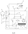
- Fig. 2A shows a second embodiment of the heat pump appliance 50.
- the main difference is that the second fluid control valve 172 is in form of a three-way valve, and it has one port connected to a tank 30 located outside of the appliance.
- the heat pump appliance 50 works in a cooling mode, as indicated by arrows, the refrigerant cycle is reversed, and the heat exchange fluid is circulated between the first heat exchanger 12 acting as an evaporator now and the space heating/cooling circuit 20 for cooling the building interiors, and in the meantime, the second fluid control valve 172 is actuated to hydraulically communicate the third heat exchanger 15 with the tank 30.
- the blower 141 can run at a minimum speed or even stop running, and the third heat exchanger 15 performs as a condenser now.
- the heat exchange fluid obtains heat energy therein from the refrigerant, and flows through lines 84, 88 to enter the tank 30.
- the heat energy is then released to fluids (could be the same as the heat exchange fluid, like water) stored in the tank 30, and the heat exchange fluid further flows back into the third heat exchanger 15 via a line 87, the second fluid control valve 172, and the line 85.
- the condensation energy released at the third heat exchanger 15 can be used to heat up the fluids within the tank 30, thereby recovering the heat energy in condensation instead of dissipating it directly into the air via the blower 141.
- the speed of the blower 141 has to be modulated to keep the condensation temperature within the compressor envelop limit.
- the refrigerant circuit R is cycled same as in the heating mode.
- the first fluid control valve 16 is actuated to allow the heat exchange fluid leaving from the first heat exchanger 12 where it obtains heat energy in condensation of the refrigerant to flow through lines 81, 84 and enter the third heat exchanger 15 where it releases part of heat energy to the refrigerant passing therethrough
- the second fluid control valve 172 is actuated to allow the heat exchange fluid exiting from the third heat exchanger 15 to pass through lines 85, 86, 82 and reach the space heating/cooling circuit 20 to release rest of the heat energy into the interior atmosphere for heating building interiors.
Landscapes
- Engineering & Computer Science (AREA)
- Physics & Mathematics (AREA)
- Mechanical Engineering (AREA)
- Thermal Sciences (AREA)
- General Engineering & Computer Science (AREA)
- Chemical & Material Sciences (AREA)
- Combustion & Propulsion (AREA)
- Analytical Chemistry (AREA)
- Power Engineering (AREA)
- Air Conditioning Control Device (AREA)
Priority Applications (2)
| Application Number | Priority Date | Filing Date | Title |
|---|---|---|---|
| EP16186509.2A EP3290827A1 (de) | 2016-08-31 | 2016-08-31 | Abtauen ohne umkehrung des kältemittelkreislaufs |
| CN201710693841.9A CN107796141A (zh) | 2016-08-31 | 2017-08-14 | 能够不反转制冷剂循环以进行除霜操作的热泵设备 |
Applications Claiming Priority (1)
| Application Number | Priority Date | Filing Date | Title |
|---|---|---|---|
| EP16186509.2A EP3290827A1 (de) | 2016-08-31 | 2016-08-31 | Abtauen ohne umkehrung des kältemittelkreislaufs |
Publications (1)
| Publication Number | Publication Date |
|---|---|
| EP3290827A1 true EP3290827A1 (de) | 2018-03-07 |
Family
ID=56851505
Family Applications (1)
| Application Number | Title | Priority Date | Filing Date |
|---|---|---|---|
| EP16186509.2A Pending EP3290827A1 (de) | 2016-08-31 | 2016-08-31 | Abtauen ohne umkehrung des kältemittelkreislaufs |
Country Status (2)
| Country | Link |
|---|---|
| EP (1) | EP3290827A1 (de) |
| CN (1) | CN107796141A (de) |
Families Citing this family (2)
| Publication number | Priority date | Publication date | Assignee | Title |
|---|---|---|---|---|
| CN111365895A (zh) * | 2018-12-26 | 2020-07-03 | 浙江省化工研究院有限公司 | 一种高效环保的余热回收系统及传热方法 |
| EP4121707B1 (de) * | 2020-03-20 | 2024-03-13 | Samster Ab | Verfahren und system zur zuführung von trocknungsluft |
Citations (7)
| Publication number | Priority date | Publication date | Assignee | Title |
|---|---|---|---|---|
| FR2469679A1 (fr) * | 1979-11-17 | 1981-05-22 | Mueller Arnold | Appareil de climatisation, en particulier pompe a chaleur |
| EP0306587A2 (de) * | 1987-09-08 | 1989-03-15 | Carrier Corporation | Wärmepumpenanlage mit Heisswasservorrichtung |
| US5921092A (en) * | 1998-03-16 | 1999-07-13 | Hussmann Corporation | Fluid defrost system and method for secondary refrigeration systems |
| US6170270B1 (en) * | 1999-01-29 | 2001-01-09 | Delaware Capital Formation, Inc. | Refrigeration system using liquid-to-liquid heat transfer for warm liquid defrost |
| JP2004108597A (ja) * | 2002-09-13 | 2004-04-08 | Mitsubishi Electric Corp | ヒートポンプシステム |
| EP2306111A1 (de) * | 2008-06-06 | 2011-04-06 | Daikin Industries, Ltd. | Heisswassersystem |
| EP2947402A1 (de) * | 2014-05-22 | 2015-11-25 | LG Electronics Inc. | Wärmepumpe |
-
2016
- 2016-08-31 EP EP16186509.2A patent/EP3290827A1/de active Pending
-
2017
- 2017-08-14 CN CN201710693841.9A patent/CN107796141A/zh active Pending
Patent Citations (7)
| Publication number | Priority date | Publication date | Assignee | Title |
|---|---|---|---|---|
| FR2469679A1 (fr) * | 1979-11-17 | 1981-05-22 | Mueller Arnold | Appareil de climatisation, en particulier pompe a chaleur |
| EP0306587A2 (de) * | 1987-09-08 | 1989-03-15 | Carrier Corporation | Wärmepumpenanlage mit Heisswasservorrichtung |
| US5921092A (en) * | 1998-03-16 | 1999-07-13 | Hussmann Corporation | Fluid defrost system and method for secondary refrigeration systems |
| US6170270B1 (en) * | 1999-01-29 | 2001-01-09 | Delaware Capital Formation, Inc. | Refrigeration system using liquid-to-liquid heat transfer for warm liquid defrost |
| JP2004108597A (ja) * | 2002-09-13 | 2004-04-08 | Mitsubishi Electric Corp | ヒートポンプシステム |
| EP2306111A1 (de) * | 2008-06-06 | 2011-04-06 | Daikin Industries, Ltd. | Heisswassersystem |
| EP2947402A1 (de) * | 2014-05-22 | 2015-11-25 | LG Electronics Inc. | Wärmepumpe |
Also Published As
| Publication number | Publication date |
|---|---|
| CN107796141A (zh) | 2018-03-13 |
Similar Documents
| Publication | Publication Date | Title |
|---|---|---|
| JP6685409B2 (ja) | 空気調和装置 | |
| US11175076B2 (en) | Free cooling refrigeration system | |
| US20230143201A1 (en) | Methods and systems for controlling integrated air conditioning systems | |
| KR102487265B1 (ko) | 히트 펌프 시스템 | |
| WO2018047331A1 (ja) | 空気調和装置 | |
| JP2010181104A (ja) | ヒートポンプ式給湯・空調装置 | |
| EP2489965A1 (de) | Heisswasserversorgungssystem für eine klimaanlage | |
| EP3244141A1 (de) | Abtauen mit durch einen kompressortreiber erzeugter wärme | |
| JP4556453B2 (ja) | ヒートポンプ給湯エアコン | |
| JP2005299935A (ja) | 空気調和装置 | |
| KR20120125857A (ko) | 이원냉동사이클을 갖는 축열장치 및 그 운전방법 | |
| EP3106768B1 (de) | Wärmequellenseitige einheit und klimatisierungsvorrichtung | |
| JP2005249319A (ja) | ヒートポンプ給湯エアコン | |
| JP2003172523A (ja) | ヒートポンプ床暖房空調装置 | |
| JP5145026B2 (ja) | 空気調和装置 | |
| EP3290827A1 (de) | Abtauen ohne umkehrung des kältemittelkreislaufs | |
| KR20070022585A (ko) | 증기 분사 시스템을 갖춘 압축기 | |
| JP4608303B2 (ja) | 蒸気圧縮式ヒートポンプ | |
| JP2020192965A (ja) | 熱交換システム | |
| KR101173736B1 (ko) | 냉장 및 냉동 복합 공조시스템 | |
| KR101649447B1 (ko) | 도시가스를 이용한 지열히트펌프 시스템 | |
| EP3196557A1 (de) | Sole/wasser-wärmepumpensystem | |
| EP3798534A1 (de) | Wärmepumpe | |
| CN114198872A (zh) | 一种机房空调、机房空调的运行控制方法及装置 | |
| KR100613502B1 (ko) | 히트 펌프식 공기조화기 |
Legal Events
| Date | Code | Title | Description |
|---|---|---|---|
| PUAI | Public reference made under article 153(3) epc to a published international application that has entered the european phase |
Free format text: ORIGINAL CODE: 0009012 |
|
| STAA | Information on the status of an ep patent application or granted ep patent |
Free format text: STATUS: THE APPLICATION HAS BEEN PUBLISHED |
|
| AK | Designated contracting states |
Kind code of ref document: A1 Designated state(s): AL AT BE BG CH CY CZ DE DK EE ES FI FR GB GR HR HU IE IS IT LI LT LU LV MC MK MT NL NO PL PT RO RS SE SI SK SM TR |
|
| AX | Request for extension of the european patent |
Extension state: BA ME |
|
| STAA | Information on the status of an ep patent application or granted ep patent |
Free format text: STATUS: REQUEST FOR EXAMINATION WAS MADE |
|
| 17P | Request for examination filed |
Effective date: 20180905 |
|
| RBV | Designated contracting states (corrected) |
Designated state(s): AL AT BE BG CH CY CZ DE DK EE ES FI FR GB GR HR HU IE IS IT LI LT LU LV MC MK MT NL NO PL PT RO RS SE SI SK SM TR |
|
| STAA | Information on the status of an ep patent application or granted ep patent |
Free format text: STATUS: EXAMINATION IS IN PROGRESS |
|
| 17Q | First examination report despatched |
Effective date: 20210705 |
|
| STAA | Information on the status of an ep patent application or granted ep patent |
Free format text: STATUS: EXAMINATION IS IN PROGRESS |