EP3290599B1 - Duschhahn mit modularisierter temperaturregelung und schaltersteuerung - Google Patents
Duschhahn mit modularisierter temperaturregelung und schaltersteuerung Download PDFInfo
- Publication number
- EP3290599B1 EP3290599B1 EP16002758.7A EP16002758A EP3290599B1 EP 3290599 B1 EP3290599 B1 EP 3290599B1 EP 16002758 A EP16002758 A EP 16002758A EP 3290599 B1 EP3290599 B1 EP 3290599B1
- Authority
- EP
- European Patent Office
- Prior art keywords
- module
- temperature control
- switch
- outlet
- fixing board
- Prior art date
- Legal status (The legal status is an assumption and is not a legal conclusion. Google has not performed a legal analysis and makes no representation as to the accuracy of the status listed.)
- Not-in-force
Links
Images

Classifications
-
- E—FIXED CONSTRUCTIONS
- E03—WATER SUPPLY; SEWERAGE
- E03C—DOMESTIC PLUMBING INSTALLATIONS FOR FRESH WATER OR WASTE WATER; SINKS
- E03C1/00—Domestic plumbing installations for fresh water or waste water; Sinks
- E03C1/02—Plumbing installations for fresh water
- E03C1/04—Water-basin installations specially adapted to wash-basins or baths
- E03C1/0408—Water installations especially for showers
-
- F—MECHANICAL ENGINEERING; LIGHTING; HEATING; WEAPONS; BLASTING
- F16—ENGINEERING ELEMENTS AND UNITS; GENERAL MEASURES FOR PRODUCING AND MAINTAINING EFFECTIVE FUNCTIONING OF MACHINES OR INSTALLATIONS; THERMAL INSULATION IN GENERAL
- F16K—VALVES; TAPS; COCKS; ACTUATING-FLOATS; DEVICES FOR VENTING OR AERATING
- F16K11/00—Multiple-way valves, e.g. mixing valves; Pipe fittings incorporating such valves
- F16K11/10—Multiple-way valves, e.g. mixing valves; Pipe fittings incorporating such valves with two or more closure members not moving as a unit
- F16K11/20—Multiple-way valves, e.g. mixing valves; Pipe fittings incorporating such valves with two or more closure members not moving as a unit operated by separate actuating members
- F16K11/207—Multiple-way valves, e.g. mixing valves; Pipe fittings incorporating such valves with two or more closure members not moving as a unit operated by separate actuating members with two handles or actuating mechanisms at opposite sides of the housing
-
- F—MECHANICAL ENGINEERING; LIGHTING; HEATING; WEAPONS; BLASTING
- F16—ENGINEERING ELEMENTS AND UNITS; GENERAL MEASURES FOR PRODUCING AND MAINTAINING EFFECTIVE FUNCTIONING OF MACHINES OR INSTALLATIONS; THERMAL INSULATION IN GENERAL
- F16K—VALVES; TAPS; COCKS; ACTUATING-FLOATS; DEVICES FOR VENTING OR AERATING
- F16K19/00—Arrangements of valves and flow lines specially adapted for mixing fluids
- F16K19/006—Specially adapted for faucets
-
- F—MECHANICAL ENGINEERING; LIGHTING; HEATING; WEAPONS; BLASTING
- F16—ENGINEERING ELEMENTS AND UNITS; GENERAL MEASURES FOR PRODUCING AND MAINTAINING EFFECTIVE FUNCTIONING OF MACHINES OR INSTALLATIONS; THERMAL INSULATION IN GENERAL
- F16K—VALVES; TAPS; COCKS; ACTUATING-FLOATS; DEVICES FOR VENTING OR AERATING
- F16K27/00—Construction of housing; Use of materials therefor
-
- E—FIXED CONSTRUCTIONS
- E03—WATER SUPPLY; SEWERAGE
- E03C—DOMESTIC PLUMBING INSTALLATIONS FOR FRESH WATER OR WASTE WATER; SINKS
- E03C2201/00—Details, devices or methods not otherwise provided for
- E03C2201/30—Diverter valves in faucets or taps
Definitions
- the present invention relates to shower tap, particularly to shower tap with modularized temperature control and switch control, according to the preamble of claim 1.
- a shower tap mechanism with temperature control and switch control is disclosed in Chinese patent database with publishing number CN20465475U , the shower tap mechanism comprises a housing, a temperature control mechanism, a switch mechanism, a first outlet module and a second outlet module.
- the temperature control mechanism and the switch mechanism are directly fixed in the housing.
- the temperature control module comprises a cool water inlet, a hot water inlet and a mixing water outlet; the cool and hot water inlet can be connected to the water resource by flexible pipes.
- the mixing water outlet of the temperature control mechanism and the mixing water inlet of the switch mechanism are fixed and connected directly or by a hard pipe.
- the first water diversion hole, a second water diversion hole of the switch mechanism are respectively fixed and connected to the first outlet module and the second outlet module directly or by a hard pipe.
- the temperature control mechanism and the switch mechanism are directly fixed in the housing, the assembly is inconvenient, the structure is complicated; secondly, the mixing water outlet of the temperature mechanism and the mixing water inlet of the switch mechanism are fixed and connected directly or by hard pipe, the first water diversion hole, a second water diversion hole of the switch mechanism are respectively fixed and connected to the first outlet module and the second outlet module directly or by a hard pipe, the hard pipe connecting requires high manufacturing precision, which is inconvenient for modularization manufacturing.
- Document EP3015610A describes a tap for a shower comprising a housing, a temperature control module, a switch module , first and second outlets and cool and hot water inlets.
- the parts of the tap are arranged in a specific constellation. Different arrangements are not foreseen.
- the present invention is provided with a shower tap with modularized temperature control and switch control, which overcomes the disadvantages of the traditional shower tap mechanism.
- a shower tap with modularized temperature control and switch control comprising a housing, a temperature control module, a temperature control operation portion, a switch module, a switch operation portion, a first outlet module and a second outlet module, the temperature control module is disposed with a cool water inlet and a hot water inlet, wherein further comprising a fixing board, the temperature control module and the switch module are fixedly assembled to the fixing board; the fixing board is fixedly assembled in the housing, the cool water inlet and the hot water inlet of the temperature control module pass through and extend out of the housing; the first outlet module and the second outlet module are fixedly assembled in the fixing board or the housing and pass through and extend out of the housing; a mixing water outlet of the temperature control module is connected to a mixing water inlet of the switch module by a flexible pipe or retractable pipe; a first water diversion hole of the switch module is connected to the first outlet module by a flexible pipe or retractable pipe, a second water diversion hole of the switch module is connected to the
- the first outlet module is fixedly assembled to the fixing board.
- the temperature control module and the switch module are assembled in the housing;
- the first outlet module comprises a L shaped joint and a first outlet joint, one end of the L shaped joint passes through the fixing board from down to up, the first outlet joint is disposed on the fixing board, the first outlet joint is fixedly assembled and connected to the end of the L shaped joint, the L shaped joint, the first outlet joint are fixedly assembled to the fixing board.
- the temperature control module and the switch module are disposed under the fixing board.
- the housing comprises a bottom shell and a cover plate;
- the bottom shell is disposed with a bottom wall, the bottom wall is disposed with an extending edge comprising a front edge and a left and right edge respectively connected to the left and right end of the front edge, the extending edge extends upwardly to form a side wall;
- the cover plate is fixed to the side wall, an assembly chamber is formed between the cover plate and the bottom shell, the fixing board is fixed to the bottom shell, the cover plate is disposed on the fixing board; the temperature control module, the switch module and the fixing board are disposed in the assembly chamber.
- the portions of the side wall corresponding to the left and right edge are respectively disposed with a hole passing through the side wall, the temperature control operation portion and the switch operation portion respectively pass through the two holes to connect to the temperature control module and the switch module.
- the bottom wall is disposed with a boss, the fixing board is contacted on the end face of the boss and is fixedly assembled by screws.
- the cover plate is a glass board
- the fixing board is a stainless steel board
- the cover plate is disposed with a through hole, the first outlet joint passes through the through hole; the second outlet module extends downwardly out of the bottom shell.
- the mixing water outlet of the temperature control module and the mixing water inlet of the switch module are connected by a flexible pipe, the first water diversion hole of the switch module is connected to the first outlet module by a flexible pipe;
- the mixing water outlet of the temperature control module, the mixing water inlet of the switch module, the first water diversion hole of the switch module and the first outlet module are respectively disposed with a connecting joint, the connecting joint and the flexible pipe are connected by that: the external revolution surface of the connecting joint is concaved with an annular groove, the end of the flexible pipe is sleeved on the connecting joint, a clamp spring is configured, the clamp spring is locked on the flexible pipe at the position corresponding to the annular groove.
- the present invention further comprises a fixing board, the temperature control module and the switch module can be firstly fixedly assembled to the fixing board, then the fixing board is assembled in the housing, on the other hand, the mixing water outlet of the temperature control module is connected to the mixing water inlet of the switch module by a flexible pipe or a retractable pipe, the first water diversion hole of the switch module is connected to the first outlet module by a flexible pipe or a retractable pipe, the difference of the space or position of the temperature control module, the switch module and the first outlet module would not influence the connecting of the waterways, therefore, the assembly adaption of the modules and the housing is well, the requirement of different user or different housing size can be satisfied; it is convenient to realize modularization manufacturing of shower taps, the cost is greatly reduced, the efficiency is improved.
- the first outlet joint and the end of the L shaped joint are fixedly assembled together and connected, such that the first outlet joint and the L shaped joint clamp the fixing board, making the three fixedly assembled together, the structure is compact and simple.
- the temperature control module, the switch module and the fixing board are disposed in the assembly chamber, the structure is compact and simple.
- the bottom wall is disposed with a boss, the fixing board is contacted on the end face of the boss and is fixedly connected by a screw, the connecting is fixing and reliable.
- the cover plate is a glass board
- the fixing board is a stainless steel board, such that the assembly is convenient, the structure is solid and reliable.
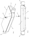
- the shower tap with modularized temperature control and switch control comprises a housing 10, a temperature control module 20, a temperature control operation portion 30, a switch module 40, a switch operation portion 50, a first outlet module 60, a second outlet module 70 and a fixing board 80.
- the fixing board 80 is a stainless steel board.
- the temperature control module 20 is disposed with a cool water inlet 21, a hot water inlet 21 and a mixing water outlet 23
- the switch module 40 is disposed with a mixing water inlet, a first water diversion hole and a second water diversion hole.
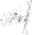
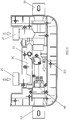
- the temperature control module 20 and the switch module 40 are fixedly assembled to the fixing board 80; the fixing board 80 is fixedly assembled in the housing 10, the temperature control module 20 and the switch module 40 are assembled in the housing 10; the temperature control module 20 and the switch module 40 are disposed under the fixing board 80; the cool water inlet and the hot water inlet of the temperature control module 20 pass through and extend out of the housing 10; the first outlet module 60 is fixedly assembled to the fixing board 80; the second outlet module 70 is fixedly assembled to the housing 10; the first outlet module 60 and the second outlet module 70 pass through and extend out of the housing 10.
- the mixing water outlet of the temperature control module is connected to the mixing water inlet of the switch module 40 by a first flexible pipe (not figured out), the first water diversion hole of the switch module 40 is connected to the first outlet module 60 by a second flexible pipe (not figured out), the second water diversion hole of the switch module 40 is directly connected and fixed to the second outlet module 70; the temperature control operation portion 30 and the switch operation portion 50 are respectively connected to the temperature control module 20 and the switch module 40, such that the user can control the temperature control module 20 and the switch module 40 respectively by the temperature control operation portion 30 and the switch operation portion 50 such to adjust the temperature and switch the waterways.
- the temperature control module 20 is disposed with a first operation element 22, the switch module 40 is disposed with a second operation element, the temperature control operation portion 30 and the switch operation portion 50 are respectively fixed to the first and second operation element to drive the operation elements to move to adjust the temperature and switch the waterways.
- the first outlet module 60 comprises a L shaped joint 61 and a first outlet joint 62, one end of the L shaped joint 61 passes through the fixing board 80 form down to up, the first outlet joint 62 is fixed to the fixing board 80, the first outlet joint 62 and the end of the L shaped joint 61 are fixedly assembled together and connected, such that the first outlet joint 62 and the L shaped joint 61 clamp the fixing board, making the three fixedly assembled together.
- the housing 10 comprises a bottom shell and a cover plate, the cover plate is a glass board, the cover plate or the housing can be served as a platform;
- the bottom shell is disposed with a bottom wall 12
- the bottom wall is disposed with an extending edge comprising a front edge and a left and right edge respectively connected to the left and right end of the front edge, the extending edge extends upwardly to form a side wall 13;
- the cover plate 11 is fixed to the side wall 13, an assembly chamber is formed between the cover plate 11 and the bottom shell, the fixing board 80 is fixed to the bottom shell, the cover plate 11 is disposed on the fixing board;
- the temperature control module, the switch module and the fixing board are disposed in the assembly chamber.
- the portions of the side wall 13 corresponding to the left and right edge are respectively disposed with a hole 14 passing through the side wall, the temperature control operation portion 30 and the switch operation portion 50 respectively pass through the two holes 14 to connect to the temperature control module 20 and the switch module 40.
- the first operation element of the temperature control module 20 and the second operation element of the switch module 40 are symmetrically and oppositely arranged.
- the bottom wall 12 is disposed with a boss 15, the fixing board 80 is contacted on the end face of the boss and is fixedly assembled by screws.
- the cover plate 11 is disposed with a through hole, the first outlet joint 62 passes through the through hole; the second outlet module 70 is L shaped, one end of the L shaped passes through the bottom wall 12 of the bottom shell and extends out.
- the mixing water outlet of the temperature control module is connected to the mixing water inlet of the switch module by a flexible pipe, the first water diversion hole of the switch module is connected to the first outlet module by a flexible pipe;
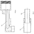
- the mixing water outlet of the temperature control module, the mixing water inlet of the switch module, the first water diversion hole of the switch module and the first outlet module are respectively disposed with a connecting joint 91, the connecting joint 91 and the flexible pipe are connected by that: the external revolution surface of the connecting joint 91 is concaved with an annular groove 92, the end of the flexible pipe is sleeved on the connecting joint 91, a clamp spring 93 is configured, the clamp spring 93 is locked on the flexible pipe at the position corresponding to the annular groove 92.
- the clamp spring 93 comprises a central portion and two suspending sections extending from two ends of the central portion, the space between the suspending portions is big then small then big from the opening to the inside, the small portion is used to realize elastic lock, such to improve the connecting strength of the flexible pipe and the connecting joint, thus ensuring the sealing performance.
- Another preferred embodiment is provided and it differs from the first embodiment in that: referring to FIG.6 , the second outlet module is threaded and connected to the joint of the second water diversion hole of the switch module.
- a third preferred embodiment is provided and it differs from the first embodiment in that: the flexible pipe is replaced by a retractable pipe, the retractable pipe comprises an external pipe 94 and an internal pipe 95 slidably connected in sleeve way.
- the present invention is provided with a shower tap with modularized temperature control and switch control, comprising a housing, a temperature control module, a temperature control operation portion, a switch module, a switch operation portion, a first outlet module and a second outlet module, the temperature control module is disposed with a cool water inlet and a hot water inlet, wherein further comprising a fixing board, the temperature control module and the switch module are fixedly assembled to the fixing board; the fixing board is fixedly assembled in the housing, the cool water inlet and the hot water inlet of the temperature control module pass through and extend out of the housing; the first outlet module and the second outlet module are fixedly assembled in the fixing board or the housing and pass through and extend out of the housing; a mixing water outlet of the temperature control module is connected to a mixing water inlet of the switch module by a flexible pipe or retractable pipe; a first water diversion hole of the switch module is connected to the first outlet module by a flexible pipe or retractable pipe, a second water diversion hole of the
- the present invention has advantages: it is convenient to realize modularization manufacturing of shower taps, the cost is largely reduced, the efficiency is improved.
Landscapes
- Engineering & Computer Science (AREA)
- General Engineering & Computer Science (AREA)
- Mechanical Engineering (AREA)
- Health & Medical Sciences (AREA)
- Life Sciences & Earth Sciences (AREA)
- Hydrology & Water Resources (AREA)
- Public Health (AREA)
- Water Supply & Treatment (AREA)
- Domestic Plumbing Installations (AREA)
Claims (10)
- Duschhahn mit modularisierter Temperatursteuerung und Schaltsteuerung, der aufweist: ein Gehäuse (10), ein Temperaturstenermodul (20), einen Temperatursteuerbedienabschnitt (30), ein Schaltmodul (40), einen Schaltbedienabschnitt (50), ein erstes Auslassmodul (60) und ein zweites Auslassmodul (70), wobei das Temperatursteuermodul (20) mit einem Kaltwassereinlass (21) und einem Heißwassereinlass (21) versehen ist, wobei der Kaltwassereinlass (21) und der Heißwassereinlass (21) des Temperatursteuermoduls (20) durch das Gehäuse (10) gehen und sich aus ihm heraus erstrecken; wobei ein erstes Wasserumleitungsloch des Schaltmoduls (40) durch eine flexible Leitung oder eine einziehbare Leitung mit dem ersten Auslassmodul (60) verbunden ist, wobei ein zweites Wasserumleitungsloch des Schaltmoduls (40) mit dem zweiten Auslassmodul (70) verbunden ist; wobei der Temperatursteuerbedienabschnitt (30) und der Schaltbedienabschnitt (50) jeweils mit dem Temperatursteuermodul (20) und dem Schaltmodul (40) verbunden sind;
dadurch gekennzeichnet, dass
der Hahn ferner aufweist:eine Befestigungsplatte, wobei das Temperatursteuermodul (20) und das Schaltmodul (40) fest an der Befestigungsplatte (80) befestigt sind;wobei die Befestigungsplatte (80) fest in dem Gehäuse montiert ist;wobei das erste Auslassmodul (60) und das zweite Auslassmodul (70) fest auf der Befestigungsplatte (80) oder in dem Gehäuse (10) montiert sind und durch das Gehäuse gehen und sich aus ihm heraus erstrecken; undwobei ein Mischauslass (23) des Temperatursteuermoduls (20) durch eine flexible Leitung oder eine einziehbare Leitung mit einem Mischwassereinlass des Schaltmoduls (40) verbunden ist. - Duschhahn mit modularisierter Temperatursteuerung und Schaltsteuerung nach Anspruch 1, wobei das erste Auslassmodul (60) fest an der Befestigungsplatte (80) montiert ist.
- Duschhahn mit modularisierter Temperatursteuerung und Schaltsteuerung nach Anspruch 1 und/oder 2, wobei das Temperatursteuermodul (20) und das Schaltmodul (40) in dem Gehäuse (10) montiert sind;
wobei das erste Auslassmodul (60) ein L-förmiges Anschlussstück (61) und ein erstes Auslassanschlussstück (62) aufweist,
wobei ein Ende des L-förmigen Anschlussstücks von oben nach unten durch die Befestigungsplatte (80) geht,
wobei das erste Auslassanschlussstück auf der Befestigungsplatte angeordnet ist, das erste Auslassanschlussstück fest an dem Ende des L-formigen Anschlussstücks montiert und damit verbunden ist, wobei das L-förmige Anschlussstück, wobei das erste Auslassstück fest an der Befestigungsplatte montiert sind. - Duschhahn mit modularisierter Temperatursteuerung und Schaltsteuerung nach einem oder mehreren der Ansprüche 1 bis 3, wobei das Temperatursteuermodul (20) und das Schaltmodul (40) unter der Befestigungsplatte (80) angeordnet sind.
- Duschhahn mit modularisierter Temperatursteuerung und Schaltsteuerung nach einem oder mehreren der Ansprüche 1 bis 4, wobei das Gehäuse (10) eine Unterschale und eine Abdeckplatte (11) aufweist;
wobei die Unterschalte mit einer Bodenwand versehen ist, wobei die Bodenwand (12) mit einer sich erstreckenden Kante versehen ist, die eine vordere Kante und eine linke und rechte Kante, die jeweils mit dem linken und rechten Ende der vorderen Kante verbunden sind, aufweist, wobei die sich erstreckende Kante sich aufwärts erstreckt, um eine Seitenwand zu bilden;
wobei die Abdeckplatte an der Seitenwand (13) befestigt ist, wobei eine Anordnungskammer zwischen der Abdeckplatte und der Unterschale ausgebildet ist, wobei die Befestigungsplatte (80) an der Unterschale befestigt ist, wobei die Abdeckplatte auf der Befestigungsplatte angeordnet ist;
wobei das Temperatursteuermodul, das Schaltmodul und die Befestigungsplatte in der Anordnungskammer angeordnet sind. - Duschhahn mit modularisierter Temperatursteuerung und Schaltsteuerung nach Anspruch 5, wobei die Abschnitte der Seitenwand (13), die der linken und rechten Kante entsprechen, jeweils mit einem Loch (14) versehen sind, das durch die Seitenwand geht, wobei der Temperatursteuerbedienabschnitt (30) und der Schaltbedienabschnitt (50) jeweils durch die zwei Löcher (14) gehen, um mit dem Temperatursteuermodul (20) und dem Schaltmodul (40) zu verbinden.
- Duschhahn mit modularisierter Temperatursteuerung und Schaltsteuerung nach Anspruch 5 und/oder 6, wobei die Bodenwand (12) mit einem Ansatz (15) versehen ist, wobei die Befestigungsplatte (80) auf der Endfläche des Ansatzes kontaktiert wird und durch Schrauben fest montiert ist.
- Duschhahn mit modularisierter Temperatursteuerung und Schaltsteuerung nach einem oder mehreren der Ansprüche 5 bis 7, wobei die Abdeckplatte 11) eine Glaspatte ist, wobei die Befestigungsplatte (80) eine nichtrostende Stahlplatte ist.
- Duschhahn mit modularisierter Temperatursteuerung und Schaltsteuerung nach einem oder mehreren der Ansprüche 5 bis 8, wobei die Abdeckplatte (11) mit einem Durchgangsloch versehen ist,
wobei das erste Auslassverbindungsstück (62) durch das Durchgangsloch geht; wobei das zweite Auslassmodul (70) sich aus der Unterschale heraus nach unten erstreckt. - Duschhahn mit modularisierter Temperatursteuerung und Schaltsteuerung nach einem oder mehreren der Ansprüche 1 bis 9, wobei der Mischwasserauslass (23) des Temperatursteuermoduls (20) und der Mischwassereinlass des Schaltmoduls (40) durch eine flexible Leitung verbunden sind, wobei das erste Wasserableitungsloch des Schaltmoduls durch eine flexible Leitung mit dem ersten Auslassmodul (60) verbunden ist;
wobei der Mischwasserauslass des Temperatursteuermoduls, der Mischwassereinlass des Schaltmoduls, das erste Wasserableitungsloch des Schaltmoduls und das erste Auslassmodul jeweils mit einem Verbindungsanschlussstück (91) versehen sind,
wobei das Verbindungsanschlussstück und die flexible Leitung dadurch verbunden sind: die äußere Rotationsfläche des Verbindungsanschlussstücks ist mit einer ringförmigen Nut (92) ausgehöhlt, das Ende der flexiblen Leitung ist auf das Verbindungsanschlusssttick geschoben, eine Klemmfeder (93) ist aufgebaut, wobei die Klemmfeder in der Position, die der ringförmigen Nut entspricht, auf der flexiblen Leitung arretiert ist.
Applications Claiming Priority (1)
| Application Number | Priority Date | Filing Date | Title |
|---|---|---|---|
| CN201610769388.0A CN107781466A (zh) | 2016-08-30 | 2016-08-30 | 模块化温控和切换控制的淋浴龙头机构 |
Publications (2)
| Publication Number | Publication Date |
|---|---|
| EP3290599A1 EP3290599A1 (de) | 2018-03-07 |
| EP3290599B1 true EP3290599B1 (de) | 2019-02-27 |
Family
ID=57754901
Family Applications (1)
| Application Number | Title | Priority Date | Filing Date |
|---|---|---|---|
| EP16002758.7A Not-in-force EP3290599B1 (de) | 2016-08-30 | 2016-12-23 | Duschhahn mit modularisierter temperaturregelung und schaltersteuerung |
Country Status (2)
| Country | Link |
|---|---|
| EP (1) | EP3290599B1 (de) |
| CN (1) | CN107781466A (de) |
Families Citing this family (1)
| Publication number | Priority date | Publication date | Assignee | Title |
|---|---|---|---|---|
| CN108413058A (zh) * | 2018-04-02 | 2018-08-17 | 曾宇杰 | 一种新型淋浴阀体 |
Family Cites Families (14)
| Publication number | Priority date | Publication date | Assignee | Title |
|---|---|---|---|---|
| US5924449A (en) * | 1993-04-23 | 1999-07-20 | Toto Ltd. | Hot and cold water mixing device |
| JP3198458B2 (ja) * | 1996-07-02 | 2001-08-13 | 千住スプリンクラー株式会社 | スプリンクラーヘッド |
| JP3713224B2 (ja) * | 2001-08-10 | 2005-11-09 | 株式会社三栄水栓製作所 | 水栓取替方法 |
| JP4046984B2 (ja) * | 2001-11-21 | 2008-02-13 | 株式会社三栄水栓製作所 | サーモ型湯水混合水栓 |
| JP2003184139A (ja) * | 2001-12-17 | 2003-07-03 | Toto Ltd | 水 栓 |
| US7389793B2 (en) * | 2006-06-27 | 2008-06-24 | Hsiang Hung Wang | Faucet device selectively operatable manually or automatically |
| CN202914843U (zh) * | 2012-10-23 | 2013-05-01 | 卢于波 | 恒温水龙头 |
| CN203885393U (zh) * | 2014-06-19 | 2014-10-22 | 厦门松霖科技有限公司 | 可自动旋转龙头水嘴的浴缸出水装置 |
| CN204083355U (zh) * | 2014-07-22 | 2015-01-07 | 厦门建霖工业有限公司 | 便捷恒温龙头结构 |
| CN204267824U (zh) * | 2014-10-30 | 2015-04-15 | 厦门建霖工业有限公司 | 过滤置物淋浴柱恒温龙头 |
| CN204654752U (zh) * | 2015-03-26 | 2015-09-23 | 淮南圣丹网络工程技术有限公司 | 一种语音控制淋浴 |
| CN205013801U (zh) * | 2015-08-21 | 2016-02-03 | 厦门建霖工业有限公司 | 按钮切换顶喷水花的装置及其控制龙头和被控顶喷 |
| CN109027378B (zh) * | 2016-04-18 | 2020-11-20 | 宁波索顿飞羽电器有限公司 | 触摸式恒温水龙头系统 |
| CN206054816U (zh) * | 2016-08-30 | 2017-03-29 | 厦门松霖科技有限公司 | 一种模块化温控和切换控制的淋浴龙头机构 |
-
2016
- 2016-08-30 CN CN201610769388.0A patent/CN107781466A/zh not_active Withdrawn
- 2016-12-23 EP EP16002758.7A patent/EP3290599B1/de not_active Not-in-force
Non-Patent Citations (1)
| Title |
|---|
| None * |
Also Published As
| Publication number | Publication date |
|---|---|
| EP3290599A1 (de) | 2018-03-07 |
| CN107781466A (zh) | 2018-03-09 |
Similar Documents
| Publication | Publication Date | Title |
|---|---|---|
| EP3219858B1 (de) | Temperaturregelnder hahn | |
| US20190009192A1 (en) | Composite filter cartridge | |
| EP4077820B1 (de) | Konfigurierbare wasserhahnvorrichtung und verfahren zur implementierung und zum betrieb derselben | |
| US12181069B2 (en) | Arbitrary directional touch switch | |
| US10280598B2 (en) | Faucet assembly | |
| CN211599633U (zh) | 一种置物淋浴器 | |
| EP3290599B1 (de) | Duschhahn mit modularisierter temperaturregelung und schaltersteuerung | |
| US20190186111A1 (en) | Multifunctional pullout kitchen faucet | |
| EP1156245A3 (de) | Wasserzapfarmatur | |
| US9217512B2 (en) | Combination of a faucet handle and a control valve | |
| EP1531005B1 (de) | Brausekopf für Küchenspüle | |
| CN107990020B (zh) | 多功能阀 | |
| US11773573B1 (en) | Anti-slip shower system | |
| US10900210B2 (en) | Drain plug linkage structure | |
| CN110319241B (zh) | 一种水龙头内本体快速安装构造 | |
| US11821183B2 (en) | Fast assembling faucet component for dual water sources | |
| CN206054816U (zh) | 一种模块化温控和切换控制的淋浴龙头机构 | |
| CN109764153B (zh) | 分水器 | |
| US11193257B2 (en) | Outlet structure of faucet valve seat | |
| GB2563702A (en) | A switch temperature control valve spool | |
| CN110056682A (zh) | 一种水路切换装置及淋浴器 | |
| US11248710B2 (en) | Single waterway valve core structure | |
| JP7278885B2 (ja) | 水栓 | |
| JP2018091053A (ja) | 混合水栓 | |
| CN106320455B (zh) | 龙头便捷安装机构 |
Legal Events
| Date | Code | Title | Description |
|---|---|---|---|
| PUAI | Public reference made under article 153(3) epc to a published international application that has entered the european phase |
Free format text: ORIGINAL CODE: 0009012 |
|
| STAA | Information on the status of an ep patent application or granted ep patent |
Free format text: STATUS: REQUEST FOR EXAMINATION WAS MADE |
|
| 17P | Request for examination filed |
Effective date: 20171017 |
|
| AK | Designated contracting states |
Kind code of ref document: A1 Designated state(s): AL AT BE BG CH CY CZ DE DK EE ES FI FR GB GR HR HU IE IS IT LI LT LU LV MC MK MT NL NO PL PT RO RS SE SI SK SM TR |
|
| AX | Request for extension of the european patent |
Extension state: BA ME |
|
| RAP1 | Party data changed (applicant data changed or rights of an application transferred) |
Owner name: XIAMEN SOLEX HIGH-TECH INDUSTRIES CO., LTD. |
|
| GRAP | Despatch of communication of intention to grant a patent |
Free format text: ORIGINAL CODE: EPIDOSNIGR1 |
|
| STAA | Information on the status of an ep patent application or granted ep patent |
Free format text: STATUS: GRANT OF PATENT IS INTENDED |
|
| RIC1 | Information provided on ipc code assigned before grant |
Ipc: E03C 1/04 20060101AFI20180531BHEP Ipc: F16K 11/20 20060101ALI20180531BHEP |
|
| INTG | Intention to grant announced |
Effective date: 20180621 |
|
| GRAJ | Information related to disapproval of communication of intention to grant by the applicant or resumption of examination proceedings by the epo deleted |
Free format text: ORIGINAL CODE: EPIDOSDIGR1 |
|
| STAA | Information on the status of an ep patent application or granted ep patent |
Free format text: STATUS: REQUEST FOR EXAMINATION WAS MADE |
|
| GRAP | Despatch of communication of intention to grant a patent |
Free format text: ORIGINAL CODE: EPIDOSNIGR1 |
|
| STAA | Information on the status of an ep patent application or granted ep patent |
Free format text: STATUS: GRANT OF PATENT IS INTENDED |
|
| INTC | Intention to grant announced (deleted) | ||
| INTG | Intention to grant announced |
Effective date: 20181127 |
|
| GRAS | Grant fee paid |
Free format text: ORIGINAL CODE: EPIDOSNIGR3 |
|
| GRAA | (expected) grant |
Free format text: ORIGINAL CODE: 0009210 |
|
| STAA | Information on the status of an ep patent application or granted ep patent |
Free format text: STATUS: THE PATENT HAS BEEN GRANTED |
|
| AK | Designated contracting states |
Kind code of ref document: B1 Designated state(s): AL AT BE BG CH CY CZ DE DK EE ES FI FR GB GR HR HU IE IS IT LI LT LU LV MC MK MT NL NO PL PT RO RS SE SI SK SM TR |
|
| REG | Reference to a national code |
Ref country code: GB Ref legal event code: FG4D |
|
| REG | Reference to a national code |
Ref country code: CH Ref legal event code: EP |
|
| REG | Reference to a national code |
Ref country code: AT Ref legal event code: REF Ref document number: 1101532 Country of ref document: AT Kind code of ref document: T Effective date: 20190315 |
|
| REG | Reference to a national code |
Ref country code: IE Ref legal event code: FG4D |
|
| REG | Reference to a national code |
Ref country code: DE Ref legal event code: R096 Ref document number: 602016010201 Country of ref document: DE |
|
| REG | Reference to a national code |
Ref country code: NL Ref legal event code: MP Effective date: 20190227 |
|
| REG | Reference to a national code |
Ref country code: LT Ref legal event code: MG4D |
|
| PG25 | Lapsed in a contracting state [announced via postgrant information from national office to epo] |
Ref country code: FI Free format text: LAPSE BECAUSE OF FAILURE TO SUBMIT A TRANSLATION OF THE DESCRIPTION OR TO PAY THE FEE WITHIN THE PRESCRIBED TIME-LIMIT Effective date: 20190227 Ref country code: LT Free format text: LAPSE BECAUSE OF FAILURE TO SUBMIT A TRANSLATION OF THE DESCRIPTION OR TO PAY THE FEE WITHIN THE PRESCRIBED TIME-LIMIT Effective date: 20190227 Ref country code: NL Free format text: LAPSE BECAUSE OF FAILURE TO SUBMIT A TRANSLATION OF THE DESCRIPTION OR TO PAY THE FEE WITHIN THE PRESCRIBED TIME-LIMIT Effective date: 20190227 Ref country code: SE Free format text: LAPSE BECAUSE OF FAILURE TO SUBMIT A TRANSLATION OF THE DESCRIPTION OR TO PAY THE FEE WITHIN THE PRESCRIBED TIME-LIMIT Effective date: 20190227 Ref country code: PT Free format text: LAPSE BECAUSE OF FAILURE TO SUBMIT A TRANSLATION OF THE DESCRIPTION OR TO PAY THE FEE WITHIN THE PRESCRIBED TIME-LIMIT Effective date: 20190627 Ref country code: NO Free format text: LAPSE BECAUSE OF FAILURE TO SUBMIT A TRANSLATION OF THE DESCRIPTION OR TO PAY THE FEE WITHIN THE PRESCRIBED TIME-LIMIT Effective date: 20190527 |
|
| PG25 | Lapsed in a contracting state [announced via postgrant information from national office to epo] |
Ref country code: HR Free format text: LAPSE BECAUSE OF FAILURE TO SUBMIT A TRANSLATION OF THE DESCRIPTION OR TO PAY THE FEE WITHIN THE PRESCRIBED TIME-LIMIT Effective date: 20190227 Ref country code: RS Free format text: LAPSE BECAUSE OF FAILURE TO SUBMIT A TRANSLATION OF THE DESCRIPTION OR TO PAY THE FEE WITHIN THE PRESCRIBED TIME-LIMIT Effective date: 20190227 Ref country code: IS Free format text: LAPSE BECAUSE OF FAILURE TO SUBMIT A TRANSLATION OF THE DESCRIPTION OR TO PAY THE FEE WITHIN THE PRESCRIBED TIME-LIMIT Effective date: 20190627 Ref country code: LV Free format text: LAPSE BECAUSE OF FAILURE TO SUBMIT A TRANSLATION OF THE DESCRIPTION OR TO PAY THE FEE WITHIN THE PRESCRIBED TIME-LIMIT Effective date: 20190227 Ref country code: GR Free format text: LAPSE BECAUSE OF FAILURE TO SUBMIT A TRANSLATION OF THE DESCRIPTION OR TO PAY THE FEE WITHIN THE PRESCRIBED TIME-LIMIT Effective date: 20190528 Ref country code: BG Free format text: LAPSE BECAUSE OF FAILURE TO SUBMIT A TRANSLATION OF THE DESCRIPTION OR TO PAY THE FEE WITHIN THE PRESCRIBED TIME-LIMIT Effective date: 20190527 |
|
| REG | Reference to a national code |
Ref country code: AT Ref legal event code: MK05 Ref document number: 1101532 Country of ref document: AT Kind code of ref document: T Effective date: 20190227 |
|
| PG25 | Lapsed in a contracting state [announced via postgrant information from national office to epo] |
Ref country code: ES Free format text: LAPSE BECAUSE OF FAILURE TO SUBMIT A TRANSLATION OF THE DESCRIPTION OR TO PAY THE FEE WITHIN THE PRESCRIBED TIME-LIMIT Effective date: 20190227 Ref country code: IT Free format text: LAPSE BECAUSE OF FAILURE TO SUBMIT A TRANSLATION OF THE DESCRIPTION OR TO PAY THE FEE WITHIN THE PRESCRIBED TIME-LIMIT Effective date: 20190227 Ref country code: RO Free format text: LAPSE BECAUSE OF FAILURE TO SUBMIT A TRANSLATION OF THE DESCRIPTION OR TO PAY THE FEE WITHIN THE PRESCRIBED TIME-LIMIT Effective date: 20190227 Ref country code: CZ Free format text: LAPSE BECAUSE OF FAILURE TO SUBMIT A TRANSLATION OF THE DESCRIPTION OR TO PAY THE FEE WITHIN THE PRESCRIBED TIME-LIMIT Effective date: 20190227 Ref country code: SK Free format text: LAPSE BECAUSE OF FAILURE TO SUBMIT A TRANSLATION OF THE DESCRIPTION OR TO PAY THE FEE WITHIN THE PRESCRIBED TIME-LIMIT Effective date: 20190227 Ref country code: AL Free format text: LAPSE BECAUSE OF FAILURE TO SUBMIT A TRANSLATION OF THE DESCRIPTION OR TO PAY THE FEE WITHIN THE PRESCRIBED TIME-LIMIT Effective date: 20190227 Ref country code: EE Free format text: LAPSE BECAUSE OF FAILURE TO SUBMIT A TRANSLATION OF THE DESCRIPTION OR TO PAY THE FEE WITHIN THE PRESCRIBED TIME-LIMIT Effective date: 20190227 Ref country code: DK Free format text: LAPSE BECAUSE OF FAILURE TO SUBMIT A TRANSLATION OF THE DESCRIPTION OR TO PAY THE FEE WITHIN THE PRESCRIBED TIME-LIMIT Effective date: 20190227 |
|
| REG | Reference to a national code |
Ref country code: DE Ref legal event code: R097 Ref document number: 602016010201 Country of ref document: DE |
|
| PG25 | Lapsed in a contracting state [announced via postgrant information from national office to epo] |
Ref country code: SM Free format text: LAPSE BECAUSE OF FAILURE TO SUBMIT A TRANSLATION OF THE DESCRIPTION OR TO PAY THE FEE WITHIN THE PRESCRIBED TIME-LIMIT Effective date: 20190227 Ref country code: PL Free format text: LAPSE BECAUSE OF FAILURE TO SUBMIT A TRANSLATION OF THE DESCRIPTION OR TO PAY THE FEE WITHIN THE PRESCRIBED TIME-LIMIT Effective date: 20190227 |
|
| PG25 | Lapsed in a contracting state [announced via postgrant information from national office to epo] |
Ref country code: AT Free format text: LAPSE BECAUSE OF FAILURE TO SUBMIT A TRANSLATION OF THE DESCRIPTION OR TO PAY THE FEE WITHIN THE PRESCRIBED TIME-LIMIT Effective date: 20190227 |
|
| PLBE | No opposition filed within time limit |
Free format text: ORIGINAL CODE: 0009261 |
|
| STAA | Information on the status of an ep patent application or granted ep patent |
Free format text: STATUS: NO OPPOSITION FILED WITHIN TIME LIMIT |
|
| 26N | No opposition filed |
Effective date: 20191128 |
|
| PG25 | Lapsed in a contracting state [announced via postgrant information from national office to epo] |
Ref country code: SI Free format text: LAPSE BECAUSE OF FAILURE TO SUBMIT A TRANSLATION OF THE DESCRIPTION OR TO PAY THE FEE WITHIN THE PRESCRIBED TIME-LIMIT Effective date: 20190227 |
|
| PG25 | Lapsed in a contracting state [announced via postgrant information from national office to epo] |
Ref country code: TR Free format text: LAPSE BECAUSE OF FAILURE TO SUBMIT A TRANSLATION OF THE DESCRIPTION OR TO PAY THE FEE WITHIN THE PRESCRIBED TIME-LIMIT Effective date: 20190227 |
|
| REG | Reference to a national code |
Ref country code: CH Ref legal event code: PL |
|
| REG | Reference to a national code |
Ref country code: BE Ref legal event code: MM Effective date: 20191231 |
|
| PG25 | Lapsed in a contracting state [announced via postgrant information from national office to epo] |
Ref country code: MC Free format text: LAPSE BECAUSE OF FAILURE TO SUBMIT A TRANSLATION OF THE DESCRIPTION OR TO PAY THE FEE WITHIN THE PRESCRIBED TIME-LIMIT Effective date: 20190227 |
|
| PG25 | Lapsed in a contracting state [announced via postgrant information from national office to epo] |
Ref country code: LU Free format text: LAPSE BECAUSE OF NON-PAYMENT OF DUE FEES Effective date: 20191223 Ref country code: FR Free format text: LAPSE BECAUSE OF NON-PAYMENT OF DUE FEES Effective date: 20191231 Ref country code: IE Free format text: LAPSE BECAUSE OF NON-PAYMENT OF DUE FEES Effective date: 20191223 |
|
| PG25 | Lapsed in a contracting state [announced via postgrant information from national office to epo] |
Ref country code: LI Free format text: LAPSE BECAUSE OF NON-PAYMENT OF DUE FEES Effective date: 20191231 Ref country code: CH Free format text: LAPSE BECAUSE OF NON-PAYMENT OF DUE FEES Effective date: 20191231 Ref country code: BE Free format text: LAPSE BECAUSE OF NON-PAYMENT OF DUE FEES Effective date: 20191231 |
|
| PG25 | Lapsed in a contracting state [announced via postgrant information from national office to epo] |
Ref country code: CY Free format text: LAPSE BECAUSE OF FAILURE TO SUBMIT A TRANSLATION OF THE DESCRIPTION OR TO PAY THE FEE WITHIN THE PRESCRIBED TIME-LIMIT Effective date: 20190227 |
|
| PG25 | Lapsed in a contracting state [announced via postgrant information from national office to epo] |
Ref country code: HU Free format text: LAPSE BECAUSE OF FAILURE TO SUBMIT A TRANSLATION OF THE DESCRIPTION OR TO PAY THE FEE WITHIN THE PRESCRIBED TIME-LIMIT; INVALID AB INITIO Effective date: 20161223 Ref country code: MT Free format text: LAPSE BECAUSE OF FAILURE TO SUBMIT A TRANSLATION OF THE DESCRIPTION OR TO PAY THE FEE WITHIN THE PRESCRIBED TIME-LIMIT Effective date: 20190227 |
|
| GBPC | Gb: european patent ceased through non-payment of renewal fee |
Effective date: 20201223 |
|
| PG25 | Lapsed in a contracting state [announced via postgrant information from national office to epo] |
Ref country code: GB Free format text: LAPSE BECAUSE OF NON-PAYMENT OF DUE FEES Effective date: 20201223 |
|
| PGFP | Annual fee paid to national office [announced via postgrant information from national office to epo] |
Ref country code: DE Payment date: 20211231 Year of fee payment: 6 |
|
| PG25 | Lapsed in a contracting state [announced via postgrant information from national office to epo] |
Ref country code: MK Free format text: LAPSE BECAUSE OF FAILURE TO SUBMIT A TRANSLATION OF THE DESCRIPTION OR TO PAY THE FEE WITHIN THE PRESCRIBED TIME-LIMIT Effective date: 20190227 |
|
| REG | Reference to a national code |
Ref country code: DE Ref legal event code: R119 Ref document number: 602016010201 Country of ref document: DE |
|
| PG25 | Lapsed in a contracting state [announced via postgrant information from national office to epo] |
Ref country code: DE Free format text: LAPSE BECAUSE OF NON-PAYMENT OF DUE FEES Effective date: 20230701 |