EP3290590A1 - Procédé et ensemble formant outil pour le retrait d'une fondation monopieu - Google Patents
Procédé et ensemble formant outil pour le retrait d'une fondation monopieu Download PDFInfo
- Publication number
- EP3290590A1 EP3290590A1 EP16186217.2A EP16186217A EP3290590A1 EP 3290590 A1 EP3290590 A1 EP 3290590A1 EP 16186217 A EP16186217 A EP 16186217A EP 3290590 A1 EP3290590 A1 EP 3290590A1
- Authority
- EP
- European Patent Office
- Prior art keywords
- pile
- lid
- monopile
- recess
- tool assembly
- Prior art date
- Legal status (The legal status is an assumption and is not a legal conclusion. Google has not performed a legal analysis and makes no representation as to the accuracy of the status listed.)
- Withdrawn
Links
- 238000000034 method Methods 0.000 title claims abstract description 33
- 238000007789 sealing Methods 0.000 claims abstract description 43
- XLYOFNOQVPJJNP-UHFFFAOYSA-N water Substances O XLYOFNOQVPJJNP-UHFFFAOYSA-N 0.000 claims abstract description 18
- 238000004873 anchoring Methods 0.000 claims abstract description 17
- 238000005086 pumping Methods 0.000 claims abstract description 14
- 239000012530 fluid Substances 0.000 claims abstract description 8
- 238000004891 communication Methods 0.000 claims abstract description 6
- 238000003801 milling Methods 0.000 claims description 10
- 239000011800 void material Substances 0.000 claims description 8
- 230000000295 complement effect Effects 0.000 claims description 6
- 230000002093 peripheral effect Effects 0.000 claims description 6
- 229910000831 Steel Inorganic materials 0.000 description 12
- 239000010959 steel Substances 0.000 description 12
- 238000009434 installation Methods 0.000 description 3
- 238000011161 development Methods 0.000 description 2
- 230000018109 developmental process Effects 0.000 description 2
- 230000007613 environmental effect Effects 0.000 description 2
- 239000007788 liquid Substances 0.000 description 2
- 238000004064 recycling Methods 0.000 description 2
- 238000002360 preparation method Methods 0.000 description 1
Images


Classifications
-
- E—FIXED CONSTRUCTIONS
- E02—HYDRAULIC ENGINEERING; FOUNDATIONS; SOIL SHIFTING
- E02D—FOUNDATIONS; EXCAVATIONS; EMBANKMENTS; UNDERGROUND OR UNDERWATER STRUCTURES
- E02D9/00—Removing sheet piles bulkheads, piles, mould-pipes or other moulds or parts thereof
- E02D9/04—Removing sheet piles bulkheads, piles, mould-pipes or other moulds or parts thereof by cutting-off under water
Definitions
- the present invention relates to a method and a tool assembly for the removal of a tubular foundation monopile mounted in the ground, such as a monopile in a seabed for an offshore structure, for instance a wind turbine.
- Monopile foundations are commonly employed to support offshore structures, such as offshore wind turbines, gas or oil rigs, etc.
- the monopile comprises a large diameter cylindrical shaped tubular pile which is driven into the seabed.
- the monopile is driven into the seabed so that it extends a predetermined length upwards, such that the top of the monopile extends above the sea surface.
- On top of the monopile the structure is then mounted thereon.
- Monopiles may also be used to support landbased structures, where the pile is driven sufficiently into the ground to provide a foundation for a structure to be mounted thereon, such as a wind turbine or the like.
- This decommissioning of monopiles today is often by cutting off the pile at a predetermined level at or below the seabed (or at ground level if it is an onshore installation). This method of decommissioning monopiles is both extensive and time consuming, and furthermore it leaves a part of the monopile at the location. However, compared to removing the monopiles the cutting off may be the most efficient from a cost perspective and from a practical perspective as such monopiles are typically located remove (offshore) positions.
- a tubular foundation monopile mounted in the ground such as a monopile in a seabed for an offshore structure, for instance a wind turbine
- said method comprising the steps of providing a bottom sealing plug on seabed inside the tubular pile; closing the top of the pile with a pressure-tight lid, said pile having anchoring means for receiving and fixing said lid to the pile such that the lid is sealing the upper opening of the pile, thereby providing an inner volume inside the pile between the bottom sealing plug and the lid; connecting pump means in fluid communication with the inner volume, and then pumping water at pressure into the inner volume, such that the inner volume extends as the pile is pulled out of the ground.
- the bottom sealing plug defines the lower end of the inner volume and this plug prevents the pressurised water in the inner volume to escape into the seabed. This in turn means that when applying a fluid pressure at a sufficiently high value inside the monopile, the lid is pressed upwards whereby the entire monopile is lifted up.
- the monopile is "converted" into a hydraulic cylinder.
- the method according to the invention is advantageous as the entire monopile is retrieved whereby all of the steel of the monopile is available for recycling. Also, it is advantageous from a cost perspective since it is substantially less cost intensive to decommission a monopile using the method according to the invention compared to hitherto known methods. The time it takes to remove the monopile is also significantly reduced using the method according to the invention.
- the anchoring means comprises an annular recess provided on the inside of the pile which is adapted to form a locking engagement with a locking ring provided on the lid. Accordingly, the method further comprises the steps of cutting said annular recess for the locking ring inside the pile, preferably by placing a milling tool inside the pile in a predetermined position, and then removing the milling tool before placing the lid inside the pile and releasing the locking ring to secure the lid to the monopile.
- the anchoring means comprises at least one recess, such as an annual recess or a series of recesses in an annular configuration, provided on the outside of the pile in a predetermined distance from the upper opening of the pile, and radially inwardly extendable locking pins are provided along the periphery of the lid to form a locking engagement with the at least one recess.
- the cutting of the recess is preferably achieved by using a subsea milling tool.
- a subsea milling tool Such type of fully submersible tool is commercially available and can be submerged and operated from a vessel.
- the step of placing a lid inside the pile includes lowering the lid to the predetermined position and then releasing the locking ring, which thereby expands into locking engagement with the recess.
- the locking ring may be hydraulically retracted during the positioning of the lid inside the monopile and the when correctly positioned the locking ring is released.
- the recess is preferably provided with an upper surface portion which is substantially horizontal, and a lower surface portion which is wedge-shaped, and that the locking ring is provided with a substantially complementary peripheral shape to secure a wedge-locking engagement between the lid and the monopile via the locking ring and the recess. This means that when the locking ring is released the lid is self-centring as well as fluid tightly self-sealing to the inside of the pile as the locking ring thereby engages the recess.
- the water is pumped into the inner volume at a pressure up to approx.1000 bar.
- the pumping of water is continued until the pile is driven out of the ground and can be lifted by suitable lifting means, such as a crane.
- the monopile is initially cut off horizontally to provide an upper opening of the pile in a predetermined distance from the seabed.
- a tool assembly for removal of a tubular foundation monopile mounted in the ground, such as a monopile in a seabed for an offshore structure, for instance a wind turbine, said apparatus comprising a bottom sealing plug on seabed inside the tubular pile; a pressure-tight lid closing the top of the pile, said pile having anchoring means for receiving and fixing said lid to the pile such that the lid is sealing the upper opening of the pile, thereby providing an inner volume inside the pile between the bottom sealing plug and the lid; and pumping means in fluid communication with the inner volume for pumping water into the inner volume at a pressure, such as a pressure of up to approx. 1000 bar.
- the anchoring means comprises an annular recess provided on the inside of the pile which is adapted to form a locking engagement with a locking ring provided on the lid.
- the recess is provided with an upper surface portion which is substantially horizontal, and a lower surface portion which is wedge-shaped, and that the locking ring is provided with a substantially complementary peripheral shape to secure a wedge-locking engagement between the lid and the monopile via the locking ring and the recess.
- the anchoring means comprises at least one recess, such as an annual recess or a series of recesses in an annular configuration, provided on the outside of the pile in a predetermined distance from the upper opening of the pile, and radially inwardly extendable locking pins are provided along the periphery of the lid to form a locking engagement with the at least one recess.
- These radially inwardly extendable locking pins are preferably hydraulically driven locking pins.
- the bottom sealing plug having an annular sealing member, such as rubber sealing ring, mounted between an upper plate and a lower plate that are provided with a pressurised void space in-between, so that the sealing plug is adapted to withstand a predetermined threshold pressure, such as 4 bars, before the upper plate is pressed towards the lower plate and the void space is reduced due to the pressure exceeding said threshold pressure thereby radially expanding the sealing member to close and seal against the inner surface of the monopile.
- a predetermined threshold pressure such as 4 bars
- a wire is provided between the bottom sealing plug and the lid.
- the bottom plug can be lifted up together with the pile.
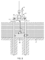
- fig. 1 the situation for decommissioning of a monopile 1 is schematically illustrated.
- the monopile 1 used to serve as a foundation for a structure (not shown), such as an offshore wind turbine.
- the monopile 1 is installed in a seabed 2.
- a vessel 3 carrying a crane 4 is then positioned next to the monopile 1 for lifting the monopile 1 out of the seabed 2 and thereby retrieving the monopile 1 for recycling.
- a tool assembly 5 is installed in the monopile 1.
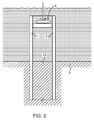
- An embodiment of such tool assembly is shown in fig. 2 installed in the monopile 1.
- the tool assembly 5 comprises a bottom sealing plug 6 positioned on the seabed 2a inside the tubular monopile 1.
- a pressure-tight lid 7 is provided at the top of the monopile 1, where anchoring means are provided for receiving and fixing the lid 7 to the monopile 1 such that the lid 7 is sealing the upper opening of the pile.
- a liquid-tight inner volume inside the monopile 1 is provided between the bottom sealing plug 6 and the lid 7.
- Pumping means 8 are provided in fluid communication with this inner volume for pumping water into the inner volume at a pressure, such as a pressure of up to approx.1000 bar. This causes the monopile 1 to move upwards as the lid 7 is anchored to the monopile 1 and the water at pressure cannot escape into the seabed 2a inside the monopile 1.
- the cylindrical monopile 1 with the tool assembly installed acts as a hydraulic cylinder.
- anchoring means are provided for securing the lid 7 to the monopile 1.
- the anchoring means comprises a locking ring 10 provided on the lid 7.
- the locking ring 10 cooperates with a recess 11 provided on the inside of the monopile 1 by milling or otherwise cutting this slot or recess 11 on cite.
- the locking ring 10 is hydraulically retracted using a hydraulic actuator 10b.
- a wedge member 10a is inserted to complete the annular locking ring 10.
- the locking ring 10 is shown in its retracted position where the wedge member 10a is retracted from the periphery of the locking ring 10.
- the recess 11 is provided with an upper surface portion 11 a which is substantially horizontal, and a lower surface portion 11 b which is inclined or wedge-shaped (see figs. 5 and 6 ).
- the locking ring 10 is provided with a substantially complementary peripheral shape to secure a wedge-locking engagement between the lid 7 and the monopile 1 via the locking ring 10 and the recess 11 (see figs. 5 and 6 ).
- the hook-like engagement between the locking ring 10 and the recess 11 also provides a liquid-tight seal, as indicated in fig. 6 .
- This geometry of the locking ring 10 and the recess 11 also ensures that the locking ring 10 is self-centring and self-sealing due to the wedge form.
- the locking ring 10 is provided with an annular hook-like mounting flange 10c which fits into a slot formed by a complementary annular mounting flange 7a provided along the periphery on the upper side of the lid 7.
- the bottom plug 6 comprises an upper steel plate 6a and a lower steel plate 6b. Between the two steel plates 6a, 6b a void space 6c is provided. The two steel plates 6a, 6b are positioned with a distance between each other due to spring members 6e provided in the void space 6c. Along the annular periphery the void space 6c is closed by a sealing ring 6d, which may be a rubber seal or a liquid expandable sealing member. The void space 6c may be pressurised. As indicated in fig.
- the sealing ring 6d is provided with an inclined surface portion 6f engaging an equally inclined annular peripheral surface of the upper steel plate 6a so that the sealing ring 6d is expanded in diameter as the upper steel plate 6a is pressed towards the lower steel plate 6b. Thereby, the sealing ring 6d is pressed against the inside of the monopile 1 and seals the bottom plug against the inside of the monopile 1.
- the bottom plug 6 according to this embodiment is designed to hold against a predetermined pressure, such as approx. 4 bars. A higher water pressure in the inner volume above the bottom plug 6 will compress the spring members 6e and then allow the seal to expand to close the gap between the periphery and the inside of the monopile 1.
- a second embodiment of the bottom plug 6 is shown.
- the upper steel plate 6a and the lower steel plate 6b are spaced apart by a distance piece 6g, which is provided with a small diameter than the two plates 6a, 6b.
- Both the upper and lower steel plates 6a, 6b are provided with inflatable sealing members 6h at their peripheries.
- the sealing members 6h may be inflated by pumping air or liquid under pressure into the sealing members 6h. This design ensures that the bottom plug 6 does not tilt during installation or during the build-up of pressure from above, e.g. due to a soft seabed or the like.
- the bottom plug 6 is preferably provided with a lifting eye 12b and the lid 7 is accordingly also provided with a mounting eye 12a so that a messenger wire 12 can be fitted to lift up the bottom plug 6 when the entire monopile 1 and the lid 7 is lifted up (see figs 1 and 2 ).
- the lid 7 is preferably also provided with a lifting eye 4a for securing the lifting wire of the crane 4 to the tool assembly when this assembly 5 is installed on the monopile 1 to be retrieved.
- the process of preparing the monopile for decommissioning according to the invention preferably includes the actions of:
- the bottom seal 6 will drop out and can be retrieved via messenger wire 12.
- the monopile 1 only has its own weight to be lifted, and once the pile 1 is on deck of the vessel 3, the lid 7 is removed by retracting the locking ring 10 and retrieving the lid 7 so that the components of the tool assembly can be used to repeat the process with the next monopile.
- a second embodiment is shown where the lid 7 is adapted for being anchored to the top of the monopile 1 externally.
- the lid 7 is fitted with an outside skirt 76 to enclose the monopile 1 when fitted (see fig. 11 ).
- the skirt 76 is fitted with sufficient hydraulic cylinders 71 to withstand the internal water pressure during retrieval of the monopile 1.
- the hydraulic cylinders 71 are fitted with hydraulic connections 73 for operating the cylinders 71.
- the monopile 1 is milled with an external recess 75, which fits the cylinders 71 on the skirt 76.
- the lid 7 is fitted to the monopile 1 (as shown in fig. 11 )
- the cylinders 71 are engaged and engagement pins 72 are extended radially inwardly into the recess 75, whereby the lid 7 is firmly mounted on the monopile 1 and the seal 74 inside the lid 7 is tight against the monopile top surface.
- the water can be injected through the water inlet 8 and the pressure will lift the monopile 1 in the manner described above.
- the monopile 1 is lifted as it comes loose by means of the lifting pad eye 4a fitted on the hook of a crane 4 or similar lifting device.
- the hydraulic cylinders 71 can be disengaged and the lid 7 removed for usage on the next pile.
Landscapes
- Engineering & Computer Science (AREA)
- Life Sciences & Earth Sciences (AREA)
- General Life Sciences & Earth Sciences (AREA)
- Mining & Mineral Resources (AREA)
- Paleontology (AREA)
- Civil Engineering (AREA)
- General Engineering & Computer Science (AREA)
- Structural Engineering (AREA)
- Foundations (AREA)
- Placing Or Removing Of Piles Or Sheet Piles, Or Accessories Thereof (AREA)
Priority Applications (1)
| Application Number | Priority Date | Filing Date | Title |
|---|---|---|---|
| EP16186217.2A EP3290590A1 (fr) | 2016-08-30 | 2016-08-30 | Procédé et ensemble formant outil pour le retrait d'une fondation monopieu |
Applications Claiming Priority (1)
| Application Number | Priority Date | Filing Date | Title |
|---|---|---|---|
| EP16186217.2A EP3290590A1 (fr) | 2016-08-30 | 2016-08-30 | Procédé et ensemble formant outil pour le retrait d'une fondation monopieu |
Publications (1)
| Publication Number | Publication Date |
|---|---|
| EP3290590A1 true EP3290590A1 (fr) | 2018-03-07 |
Family
ID=56842725
Family Applications (1)
| Application Number | Title | Priority Date | Filing Date |
|---|---|---|---|
| EP16186217.2A Withdrawn EP3290590A1 (fr) | 2016-08-30 | 2016-08-30 | Procédé et ensemble formant outil pour le retrait d'une fondation monopieu |
Country Status (1)
| Country | Link |
|---|---|
| EP (1) | EP3290590A1 (fr) |
Cited By (3)
| Publication number | Priority date | Publication date | Assignee | Title |
|---|---|---|---|---|
| CN113718819A (zh) * | 2021-08-31 | 2021-11-30 | 江苏砺诚交通科技有限公司 | 一种预制装配式风电塔筒基础及装配方法 |
| WO2022038219A1 (fr) | 2020-08-21 | 2022-02-24 | Treehouse Denmark Aps | Procédé et ensemble outil pour le retrait d'une fondation monopieu |
| CN116591165A (zh) * | 2023-04-26 | 2023-08-15 | 江苏科技大学 | 一种用于拆除海上风电桩基的新型背驼系统及方法 |
Citations (2)
| Publication number | Priority date | Publication date | Assignee | Title |
|---|---|---|---|---|
| US4808037A (en) * | 1987-02-25 | 1989-02-28 | Franklin C. Wade | Method and apparatus for removal of submerged offshore objects |
| US20150211202A1 (en) * | 2014-01-28 | 2015-07-30 | Paige Melancon | Pile Cutter |
-
2016
- 2016-08-30 EP EP16186217.2A patent/EP3290590A1/fr not_active Withdrawn
Patent Citations (2)
| Publication number | Priority date | Publication date | Assignee | Title |
|---|---|---|---|---|
| US4808037A (en) * | 1987-02-25 | 1989-02-28 | Franklin C. Wade | Method and apparatus for removal of submerged offshore objects |
| US20150211202A1 (en) * | 2014-01-28 | 2015-07-30 | Paige Melancon | Pile Cutter |
Cited By (3)
| Publication number | Priority date | Publication date | Assignee | Title |
|---|---|---|---|---|
| WO2022038219A1 (fr) | 2020-08-21 | 2022-02-24 | Treehouse Denmark Aps | Procédé et ensemble outil pour le retrait d'une fondation monopieu |
| CN113718819A (zh) * | 2021-08-31 | 2021-11-30 | 江苏砺诚交通科技有限公司 | 一种预制装配式风电塔筒基础及装配方法 |
| CN116591165A (zh) * | 2023-04-26 | 2023-08-15 | 江苏科技大学 | 一种用于拆除海上风电桩基的新型背驼系统及方法 |
Similar Documents
| Publication | Publication Date | Title |
|---|---|---|
| US20240286713A1 (en) | Marine suction anchor | |
| CN107905238B (zh) | 一种土塞抽离式吸力锚基础及其施工方法 | |
| EP3574149B1 (fr) | Procédé et outil pour l'installation d'une éolienne en mer | |
| JP7098635B2 (ja) | 水上船舶のクレーンで使用するシステム | |
| KR101633440B1 (ko) | 선박고정용 레그 설치장치 및 이를 이용한 레그 설치방법 | |
| US4041711A (en) | Method and apparatus for quickly erecting off-shore platforms | |
| US9868492B1 (en) | Tool assembly for installing a suction pile | |
| EP3290590A1 (fr) | Procédé et ensemble formant outil pour le retrait d'une fondation monopieu | |
| NO20111073A1 (no) | Rigglost forlatelsessystem | |
| US6203248B1 (en) | Sliding-resistant bottom-founded offshore structures | |
| EP2981653B1 (fr) | Procédé permettant de lever une plate-forme marine | |
| US20150240440A1 (en) | Methods and Connectors for Making Structural Connections Without Offshore Welding of Connectors | |
| GB2555719A (en) | Method for installing a pile | |
| US10513887B1 (en) | Self-elevating drilling unit drills petroleum well offshore with wellhead on seabed | |
| US20110253024A1 (en) | Anchor and methods | |
| US8678707B1 (en) | Well-head blowout containment system | |
| KR20150116738A (ko) | 해양 콘크리트 구조물의 인양 보조장치 | |
| WO2022038219A1 (fr) | Procédé et ensemble outil pour le retrait d'une fondation monopieu | |
| EP3794183B1 (fr) | Procédé de suppression d'une plateforme fixe offshore | |
| AU2009294225B2 (en) | Tideway anchor system | |
| US12509839B2 (en) | System and method for suction anchor deployment with solid lid | |
| US20130011202A1 (en) | Tideway positioning system | |
| JP5031062B2 (ja) | 取水口 | |
| KR20250172661A (ko) | 해저 내에 정박시키기 위한 디바이스 | |
| KR20160009326A (ko) | 해양 구조물 지지용 파일 시공방법 |
Legal Events
| Date | Code | Title | Description |
|---|---|---|---|
| PUAI | Public reference made under article 153(3) epc to a published international application that has entered the european phase |
Free format text: ORIGINAL CODE: 0009012 |
|
| AK | Designated contracting states |
Kind code of ref document: A1 Designated state(s): AL AT BE BG CH CY CZ DE DK EE ES FI FR GB GR HR HU IE IS IT LI LT LU LV MC MK MT NL NO PL PT RO RS SE SI SK SM TR |
|
| AX | Request for extension of the european patent |
Extension state: BA ME |
|
| STAA | Information on the status of an ep patent application or granted ep patent |
Free format text: STATUS: THE APPLICATION IS DEEMED TO BE WITHDRAWN |
|
| 18D | Application deemed to be withdrawn |
Effective date: 20180908 |