EP3290585A1 - Procédé de traitement de traitement de sol et engin automobile - Google Patents
Procédé de traitement de traitement de sol et engin automobile Download PDFInfo
- Publication number
- EP3290585A1 EP3290585A1 EP17178919.1A EP17178919A EP3290585A1 EP 3290585 A1 EP3290585 A1 EP 3290585A1 EP 17178919 A EP17178919 A EP 17178919A EP 3290585 A1 EP3290585 A1 EP 3290585A1
- Authority
- EP
- European Patent Office
- Prior art keywords
- milling drum
- construction machine
- working operation
- drive
- milling
- Prior art date
- Legal status (The legal status is an assumption and is not a legal conclusion. Google has not performed a legal analysis and makes no representation as to the accuracy of the status listed.)
- Granted
Links
Images

Classifications
-
- E—FIXED CONSTRUCTIONS
- E01—CONSTRUCTION OF ROADS, RAILWAYS, OR BRIDGES
- E01C—CONSTRUCTION OF, OR SURFACES FOR, ROADS, SPORTS GROUNDS, OR THE LIKE; MACHINES OR AUXILIARY TOOLS FOR CONSTRUCTION OR REPAIR
- E01C23/00—Auxiliary devices or arrangements for constructing, repairing, reconditioning, or taking-up road or like surfaces
- E01C23/06—Devices or arrangements for working the finished surface; Devices for repairing or reconditioning the surface of damaged paving; Recycling in place or on the road
- E01C23/08—Devices or arrangements for working the finished surface; Devices for repairing or reconditioning the surface of damaged paving; Recycling in place or on the road for roughening or patterning; for removing the surface down to a predetermined depth high spots or material bonded to the surface, e.g. markings; for maintaining earth roads, clay courts or like surfaces by means of surface working tools, e.g. scarifiers, levelling blades
- E01C23/085—Devices or arrangements for working the finished surface; Devices for repairing or reconditioning the surface of damaged paving; Recycling in place or on the road for roughening or patterning; for removing the surface down to a predetermined depth high spots or material bonded to the surface, e.g. markings; for maintaining earth roads, clay courts or like surfaces by means of surface working tools, e.g. scarifiers, levelling blades using power-driven tools, e.g. vibratory tools
- E01C23/088—Rotary tools, e.g. milling drums
-
- E—FIXED CONSTRUCTIONS
- E01—CONSTRUCTION OF ROADS, RAILWAYS, OR BRIDGES
- E01C—CONSTRUCTION OF, OR SURFACES FOR, ROADS, SPORTS GROUNDS, OR THE LIKE; MACHINES OR AUXILIARY TOOLS FOR CONSTRUCTION OR REPAIR
- E01C23/00—Auxiliary devices or arrangements for constructing, repairing, reconditioning, or taking-up road or like surfaces
- E01C23/06—Devices or arrangements for working the finished surface; Devices for repairing or reconditioning the surface of damaged paving; Recycling in place or on the road
- E01C23/12—Devices or arrangements for working the finished surface; Devices for repairing or reconditioning the surface of damaged paving; Recycling in place or on the road for taking-up, tearing-up, or full-depth breaking-up paving, e.g. sett extractor
- E01C23/122—Devices or arrangements for working the finished surface; Devices for repairing or reconditioning the surface of damaged paving; Recycling in place or on the road for taking-up, tearing-up, or full-depth breaking-up paving, e.g. sett extractor with power-driven tools, e.g. oscillated hammer apparatus
- E01C23/127—Devices or arrangements for working the finished surface; Devices for repairing or reconditioning the surface of damaged paving; Recycling in place or on the road for taking-up, tearing-up, or full-depth breaking-up paving, e.g. sett extractor with power-driven tools, e.g. oscillated hammer apparatus rotary, e.g. rotary hammers
-
- E—FIXED CONSTRUCTIONS
- E01—CONSTRUCTION OF ROADS, RAILWAYS, OR BRIDGES
- E01C—CONSTRUCTION OF, OR SURFACES FOR, ROADS, SPORTS GROUNDS, OR THE LIKE; MACHINES OR AUXILIARY TOOLS FOR CONSTRUCTION OR REPAIR
- E01C2301/00—Machine characteristics, parts or accessories not otherwise provided for
Definitions
- the invention relates to a method for processing floor coverings, and a self-propelled construction machine, in particular a road milling machine, soil stabilizer, recycler or surface miner according to the preamble of claims 1 and 10.
- Self-propelled construction machines for processing floor coverings are for example from the DE 10 2006 024 123 B4 known.
- the self-propelled construction machine described therein has a machine frame, as well as a height-adjustable milling drum for processing a floor covering.
- the milling drum is driven by a drive unit.
- Such a construction machine has a control device for monitoring and controlling the milling depth of the milling drum and the speed of the construction machine.
- the drive unit drives the milling drum via a traction mechanism gear and the drive milling drum can be switched via an example.
- Mechanical clutch
- the invention is therefore an object of the invention to provide a construction machine, and a method for processing floor coverings, with which the operation is optimized.
- the invention provides in an advantageous manner that an interruption of the working operation is detected and interrupted when detected, interrupted operation of the drive of the milling drum.
- the detection of the interruption of the working operation and the interruption of the drive of the milling drum is carried out automatically.
- the present invention has the advantage that the milling drum, when it is not in the working mode, is not driven and thus the energy consumption of the construction machine is reduced.
- the milling drum is in working mode when the construction machine is working the ground, i. when the construction machine moves forward and the milling drum rotates and engages the ground.
- At least one operating parameter of the construction machine can be checked.
- the at least one operating parameter of the construction machine which can be checked for detecting the interruption of the working operation, may in particular be an actual operating parameter of the construction machine.
- An actual operating parameter is an operating parameter that reflects the current state of the construction machine.
- the operating parameters are relevant, which indicate whether the construction machine is stationary and / or the milling drum is in engagement with the floor covering.
- Engaging with the flooring means that the milling drum is in contact with the flooring and can machine it in that position.
- the at least one operating parameter in particular the at least one actual operating parameter, can be compared with at least one predetermined limit value.
- the at least one operating parameter which may be checked for detecting the interruption of the working operation, may be the actual cutting depth and / or the actual speed.
- the actual milling depth can be checked whether the milling drum is in engagement with the floor covering.
- the actual milling depth has a positive value when the milling drum is in engagement with the floor covering, and when the milling drum is raised and thus spaced from the floor covering, the milling depth has a negative amount.
- an interruption of the working operation can be detected when the actual speed of the construction machine is zero. This means that the work operation is interrupted when the construction machine is stopped.
- the speed input device of the construction machine and / or the movement of the travel devices and / or the hydraulic pressure of the landing gear motors that drives the driving device can be checked.
- the construction machine has driving devices with which the construction machine can drive over the floor covering.
- the driving devices may be wheels or crawler tracks that are connected to the machine frame via lifting columns.
- the driving devices are preferably driven by hydraulic motors.
- the actual speed of the construction machine can be checked by checking the target speed at the speed input device.
- the target speed of the construction machine is zero, then usually the actual speed is zero, since the construction machine has no roll operation, so that the construction machine comes to a standstill immediately as soon as the target speed is zero.
- the milling drum When interrupting the drive of the milling drum, the milling drum can be decoupled from the drive unit and / or in an electric or hydraulic drive unit, the drive unit can be turned off.
- the interruption of the working operation of the milling drum can take place only at a predetermined time delay.
- the milling drum After the drive of the milling drum has been interrupted, it can be detected whether the working operation is to be continued and wherein upon detecting the intended continuation of the working operation, the milling drum is driven again.
- At least one operating parameter of the construction machine For detecting the intended continuation of the working operation, at least one operating parameter of the construction machine can be checked.
- the at least one operating parameter, which is checked for detecting the intended continuation of the working operation may in particular be a desired operating parameter of the construction machine.
- a desired operating parameter is an operating parameter that reflects a state of the construction machine preset by the operator.
- the operating parameter, which is checked for detecting the intended continuation of the working operation, the target speed of the construction machine and / or the desired cutting depth and / or the actual cutting depth may be.
- An intended continuation of the working operation can be detected when the target speed of the construction machine is greater than zero, no reverse driving is detected and the target cutting depth exceeds a predetermined limit.
- the limit value for the desired milling depth can be zero, for example.
- the limit value must be selected so as to ensure that the intended continuation of the working operation is detected when a set milling depth is set at which the milling drum can come into engagement with the ground when it reaches the set milling depth. It can be taken into account when choosing the limit and a certain amount of security.
- the movement of the construction machine and / or a lowering of the milling drum can be delayed so long that the milling drum has reached a predetermined operating speed. This ensures that when it comes to contact between the milling drum and floor covering, the milling drum has reached an operating speed.
- either the speed of the milling drum can be detected directly, for example via a sensor, or the resumption of the milling operation can be delayed after re-driving the milling drum for a certain period of time to ensure that the milling drum has reached the operating speed again.
- the milling drum may be raised a predetermined amount after detecting an interruption of the work operation, especially when the interruption of the work operation is carried out because the actual speed is zero. This also ensures that when the milling drum is driven again the milling drum is not in contact with the floor covering until the milling drum has reached an operating speed.
- the milling drum can be driven again after detecting the continuation of the working operation and then lowered.
- a visual or audible signal may indicate that the milling operation has been automatically interrupted. This ensures that the operator and / or staff in the environment of the construction machine are always aware that an automatic connection of the milling drum can take place if the work operation is to be continued.
- the construction machine occupies a defined position (or a position range) relative to the floor covering before the renewed driving of the milling drum. For example, if the machine frame raised above the lifting columns, parts of the milling drum can be exposed, which can lead to the fact that when the milling drum is driven at that moment, in the milling drum box existing material is ejected from this. Therefore, for example, prior to the renewed driving of the milling drum, a defined milling depth can be set automatically, in which the milling drum is not yet engaged with the ground, but an escape of material from the milling drum housing is precluded.
- the milling drum housing is closed to the outside.
- the power output of the drive unit may be e.g. the speed can be reduced in a motor used as a drive unit. Before driving the milling drum again, it is accordingly increased again.
- the milling drum After interrupting the drive of the milling drum, it may be provided that it continues to rotate due to inertia. Alternatively, it may also be provided that it is braked, for example in order to recover the rotational energy for an energy store. The energy could be stored and then used when re-connecting the milling drum.
- the automatic of detecting the interruption of the work operation, the interruption of the driving of the milling drum, the detection of the continuation of the work operation, and the re-driving of the milling drum can be activated / deactivated by the operator.
- the self-propelled construction machine may also have driving devices, wherein the driving devices may have wheels or crawler tracks, which can be connected via lifting columns height adjustable with the machine frame.
- the height adjustment of the lifting columns can be done, for example, via hydraulic piston-cylinder units.
- the drive unit may in particular be a drive motor.
- the self-propelled construction machine can have one or more operating devices, which have at least one speed input device and one milling depth input device.
- the milling drum can be accommodated in a milling drum housing.
- the milling drum housing may have at the front sides of a left and a right edge protection, on the front side via a hold-down and on the rear side via a scraper, which the working space of the milling drum to the outside.
- the construction machine can also have front and rear roller flaps for sealing the working space.
- the milling drum can be mounted in the machine frame.
- the milling drum can be connected directly to the machine frame.
- the regulation of the milling depth can then be done by a height adjustment of the lifting columns with which the chassis of the construction machine are connected to the machine frame.
- the milling drum can be adjusted in height relative to the machine frame.
- the function that the monitoring device detects the interruption of the working operation and emits a signal for interrupting the drive of the milling drum upon detection of the interruption may be an additional function that can be switched on and off.
- the monitoring device can check at least one operating parameter of the construction machine.
- the at least one operating parameter of the construction machine which is checked for detecting the interruption of the working operation, may be an actual operating parameter, in particular the actual speed of the construction machine and / or the actual milling depth.
- the monitoring device can interrogate the at least one operating parameter of the construction machine from the control device and / or sensors and compare the at least one interrogated operating parameter with at least one predetermined limit value.
- the at least one predetermined limit value can be stored in the monitoring device.
- the at least one predetermined limit can be determined by experiments.
- the monitoring device can detect an interruption of the working operation and deliver a signal for interrupting the drive of the milling drum when the actual speed of the construction machine is zero.
- the construction machine may include a power transmission device for transmitting a drive power from a drive unit to the milling drum.
- the monitoring device can deliver the signal for interrupting the drive of the milling drum to the power transmission device or the control device and the power transmission device can interrupt the drive of the milling drum.
- the power transmission device can for this purpose have a coupling, so that the milling drum is decoupled from the drive unit when a signal for interrupting the drive is delivered to the power transmission device.
- the monitoring device can detect an interruption of the working operation and deliver the signal for interrupting the drive of the milling drum when the actual cutting depth of the construction machine falls below a limit.
- the monitoring device can detect an interruption of the working operation and release the signal for interrupting the drive of the milling drum only after a predetermined time delay.
- the monitoring device can detect after the interruption of the drive of the milling drum, whether the working operation should be continued and deliver on detection of the intended continuation of the working operation, a second signal to re-driving the milling drum.
- the monitoring device can be used to detect the intended continuation of the working operation of the at least one operating parameter of the construction machine by the control device and / or an operating device and / or by Sensors, which measure the at least one operating parameter, query and compare the at least one operating parameter with at least one predetermined limit.
- the at least one predetermined limit value can be stored in the monitoring device or the control device.
- the at least one predetermined limit can be determined by experiments.
- the at least one operating parameter, which the monitoring device checks for detecting the intended continuation of the operating mode is in particular a desired operating parameter, since the intended continuation of the operating mode is already to be detected.
- the desired operating parameters are intended operating parameters of the construction machine. These may be, for example, the operating parameters entered at the operating device.
- the at least one operating parameter which is to be monitored for detecting the intended continuation of the working operation can be, in particular, the desired speed and / or set milling depth and / or the actual milling depth.
- the set speed and / or the set depth of cut may in particular be the values entered in the speed input device and / or routing depth input device of the control device.
- the actual speed may be measured via sensors which control the movement and / or the position of the driving devices and / or the hydraulic pressure of the chassis motors which drives the driving device.
- the actual milling depth can be determined by sensors which are arranged in or at the height adjustment.
- the height adjustment can be the lifting columns of the construction machine.
- the sensors for measuring the actual milling depth can also measure the distance between the machine frame and the ground surface.
- the sensors can also be arranged on a scraper blade arranged behind the milling drum or on side plates surrounding the milling drum. Also, any other sensors may be provided which can determine the depth of cut.
- the monitoring device may be part of the control device.
- the operating device may also be part of the control device.
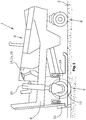
- Fig. 1 shows a self-propelled construction machine 1 for processing of floor coverings 2.
- the construction machine 1 has at least one machine frame 4. Furthermore, the construction machine has a height-adjustable milling drum 12 for processing the floor covering 2, wherein in a working operation the milling drum 12 processes the floor covering 2.
- the milling drum 12 may be housed in a Fräswalzengephaseuse.
- the milling drum housing can have at the front sides a left and a right edge protection 24, at the front side via a hold-down device and at the rear side via a scraper 22, whereby they close the working space of the milling drum 12 to the outside.
- the construction machine 1 further has a control device 14 for monitoring and controlling the milling depth of the milling drum 12 and the speed of the construction machine 1.
- the milling drum 12 is driven by a drive unit 6.
- the drive unit 6 is preferably a drive motor, in particular an internal combustion engine. Alternatively, the drive unit may also be an electric or hydraulic motor.
- the construction machine 1 also has front and rear driving devices 8, 9. These driving devices 8, 9 may be wheels or crawler tracks.
- the rear driving devices 9 are connected via lifting columns 20, for example by means of piston-cylinder units height adjustable with the machine frame 4.
- the front driving device 8 is also connected to the machine frame 4.
- the front driving devices 8 can also be connected to the machine frame differently than shown via lifting columns.
- the construction machine 1 or the machine frame 4 can be adjusted in height relative to the floor covering.
- the lifting columns 20 of the machine frame 4 is adjusted in height and thus the mounted in the machine frame 4 milling drum 12 is height-adjusted.
- the construction machine 1 is shown with raised milling drum 12.
- the milling drum can be adjusted in height relative to the machine frame.
- an interruption of the working operation is detected and interrupted when detected, interrupted operation of the drive of the milling drum 12.
- the monitoring device 15 detects an interruption of the working operation and the monitoring device 15 outputs a signal for interrupting the drive of the milling drum 12 upon detection of the interruption of the working operation.
- the monitoring device 15 checks operating parameters of the construction machine 1. The operating parameters are compared with predetermined limit values that may be stored in the monitoring device.
- the operating parameters which are checked for detecting the interruption of the working operation, may in particular be the actual speed of the construction machine 1 and / or actual milling depth.
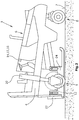
- the working operation is interrupted. Furthermore, the working operation is interrupted when the milling drum 12 is no longer in engagement with the floor covering 2. This is for example in Fig. 2 the case. There, the milling drum 12 is no longer in engagement with the floor covering 2. In this case, the working operation is interrupted.
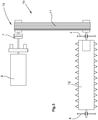
- Fig. 3 the drive train of the construction machine 1 is shown.
- a drive unit 6 which is preferably a drive motor, in particular an internal combustion engine
- the drive power is transmitted to the milling drum 12 via a power transmission device 13.
- the power transmission device has a clutch 7 and a roller drive 10.
- the roller drive 10 drives the milling drum 12 with the aid of a belt drive 11.
- a signal is delivered to the power transmission, which interrupts the drive of the milling drum 12.
- the drive unit 6 is decoupled from the milling drum 12 by means of the clutch 7.
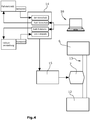
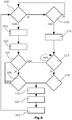
- Fig. 4 a diagram is shown, which represents the waveforms between the control device 14, monitoring device 15, operating device 16, travel drive, height adjustment, drive unit 6 and milling roller 12. To detect the interruption of the working operation, the monitoring device 15 checks operating parameters of the construction machine.
- the monitoring device interrogates the operating parameters from the control device 14.
- the operating parameters that can be queried by the control device 14 include the actual speed, the target speed, the desired cutting depth and the actual milling depth.
- the monitoring device 15 compares the queried operating parameters with predetermined limit values. To detect the interruption of the working operation In particular, the actual operating parameters are queried. Therefore, in particular the actual speed, which is referred to as actual feed, and / or the actual milling depth are interrogated by the monitoring device 15 and compared with predetermined limit values.
- the control unit receives data from sensors on the actual speed and the actual milling depth.
- the sensors for determining the actual speed can be arranged on parts of the travel drive.
- the traction drive comprises the driving devices and chassis motors for driving the driving devices, wherein preferably each driving device is assigned a running gear motor.
- the chassis motors may be hydraulic motors and fed by a common hydraulic pump.
- any other sensors can be used which can determine the actual speed of the construction machine 1.
- the actual milling depth is detected by sensors which are arranged on the height adjustment, for example on the lifting columns or on the piston-cylinder units. However, the sensors can also be arranged at any other location, provided that they can determine the actual milling depth. For example, they may be arranged on the stripping plate 22 and / or the side plates 24. The skilled person are other sensors for determining the milling depth such. B. ultrasonic sensors known. The exact procedure for determining the cutting depth is not important to the invention, it merely has to be ensured that one can reliably be detected when the milling drum is out of engagement with the ground surface in order to detect an interruption of the working operation.
- the monitoring device determines by comparison of the operating parameters with predetermined limit values that the operating mode is interrupted, the monitoring device outputs a signal to the power transmission device 13.
- the power transmission device 13 has means for interrupting the power flow.
- the means for interrupting the power flow is a clutch, as in Fig. 3 is shown.
- the means for interrupting the power flow is interrupted to the drive of the milling drum. If the means for interrupting the power flow is a clutch 7, the milling drum 12 is decoupled from the drive unit 6 when the operating mode is interrupted.
- the milling drum 12 After the drive of the milling drum 12 has been interrupted, it is detected whether the working operation should be continued. Upon detecting the intended continuation of the working operation, the milling drum 12 is driven again. For detecting the monitoring device 15 after the interruption of the drive of the milling drum 12, whether the working operation should be continued and are on detection of the intended continuation of the working operation, a second signal to re-driving the milling drum 12 from. In this case, the monitoring device 15 outputs the second signal for re-driving the milling drum 12, in particular to the power transmission device 13.
- the monitoring device 15 interrogates operating parameters from the control device 14 for detecting the intended continuation of the operating mode and compares the queried operating parameters with predetermined limit values that may be stored in the monitoring device 15. In this case, to detect the intended continuation of the working operation, in particular the desired operating parameters are queried. In this case, the setpoint speed and the set routing depth are preferably interrogated. These can be queried by the control device and / or the operating device.
- the monitoring device 15 can also query the operating parameters directly from the sensors or directly from the operating device 16.
- the monitoring device 15 can detect an interruption of the working operation and release the signal for interrupting the drive of the milling drum only after a predetermined time delay.
- the monitoring device 15 may delay the movement of the construction machine 1 and / or a lowering of the milling drum 12 until the milling drum 12 has reached a predetermined operating speed again.
- Fig. 5 is also shown that also sensors can be arranged on the milling drum 12, which measure the rotational speed of the milling drum 12.
- the monitoring device 15 can query the operating speed determined by a sensor from the control unit or directly from the sensors.
- the milling drum 12 can be raised upon detecting an interruption of the work operation.
- the milling drum 12 can then be re-driven after detecting the intended continuation of the working operation and then lowered. This ensures that the milling drum 12 is only in contact with the floor covering 2 when the milling drum 12 has reached an operating speed.
- Fig. 6 shows a flowchart for detecting the interruption of the working operation and the planned continuation of the working operation.
- the actual speed of the milling machine interrogated from the control device 14 or sensors is compared to a limit value, in particular to determine whether the feed, i. the speed of the construction machine 1 is greater than 0.
- the actual milling depth determined from the control device 14 or sensors is compared with a limit value, in particular it is determined whether the milling roller 12 is in engagement with the ground at the set milling depth ,
- an interruption of the operating mode is detected.
- the milling drum can be raised by a predetermined amount.
- the drive of the milling drum is interrupted.
- the set milling depth which can also be queried by the control unit 14 or by the operating unit 16, monitored, wherein it is checked whether it falls below a preset limit.
- Step 104 it is monitored whether in addition to the standstill of the machine and the milling drum 12 is out of engagement with the ground. If the set milling depth is still greater than the limit value, the next step in block 104 is to check whether a setpoint speed greater than zero has been set again, ie whether the machine operator would like to resume work mode by increasing the speed. Steps 103 and 104 run continuously during machine downtime until either the milling depth is changed or the feed rate is increased again.
- step 104 it can also be checked in step 104 whether the machine operator has increased the set milling depth, ie whether the milling depth should be increased when the machine is stationary.
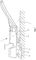
- Fig. 7 shows a construction machine 1 as a so-called large milling machine, which differs from the construction machine according to Fig. 1 among other things, characterized in that the front and rear driving means 40 are chain drives and the front and the rear driving means 40 are connected via lifting columns with the machine frame 4.
- the detection of the interruption of the working operation or the intended continuation of the working operation takes place in an analogous manner via the monitoring of the operating parameters.
- controller 14 and monitor 15 may include a general purpose processor, a Digital Signal Processor (DSP), an Application Specific Integrated Circuit (ASIC), a Field Programmable Gate Array (FPGA), or other programmable logic circuits, discrete gate or transistor logic, discrete Or be part of, or part of, hardware components, or combination thereof, as long as they are programmable to perform the features described above.
- DSP Digital Signal Processor
- ASIC Application Specific Integrated Circuit
- FPGA Field Programmable Gate Array
- a general-purpose processor may be a microprocessor, microcontroller, state machine, or a combination of computing devices, eg, a combination a DSP and a microprocessor, a variety of microprocessors, or any other known configuration.
- the method steps of the method described above may be implemented directly by hardware components or by a software module executed by a processor or a combination thereof.
- the software module may reside on a RAM memory, a flash memory, a ROM memory, an EPROM memory, an EEPROM memory, a register, a hard disk, a removable hard disk, a CD-ROM or any other form of computer readable storage medium.
- the computer readable storage medium may be coupled to the controller and / or monitor so that the controller and / or the monitor may retrieve the information from the computer readable storage medium and store information on the computer readable storage medium.
- the computer-readable storage medium may alternatively also be an integral part of the control device and / or monitoring device.
- the control device and / or monitoring device and the computer-readable storage medium may be located in an ASIC.
- the ASIC can be located in a user terminal.
- the control device and / or monitoring device and / or the computer-readable storage medium may be located as discrete components in a user terminal.
Landscapes
- Engineering & Computer Science (AREA)
- Mining & Mineral Resources (AREA)
- Architecture (AREA)
- Civil Engineering (AREA)
- Structural Engineering (AREA)
- Mechanical Engineering (AREA)
- Road Repair (AREA)
- Operation Control Of Excavators (AREA)
Applications Claiming Priority (1)
| Application Number | Priority Date | Filing Date | Title |
|---|---|---|---|
| DE102016216216.0A DE102016216216A1 (de) | 2016-08-29 | 2016-08-29 | Verfahren zum Bearbeiten von Bodenbelägen, sowie selbstfahrende Baumaschine |
Publications (2)
| Publication Number | Publication Date |
|---|---|
| EP3290585A1 true EP3290585A1 (fr) | 2018-03-07 |
| EP3290585B1 EP3290585B1 (fr) | 2020-04-29 |
Family
ID=59269862
Family Applications (1)
| Application Number | Title | Priority Date | Filing Date |
|---|---|---|---|
| EP17178919.1A Active EP3290585B1 (fr) | 2016-08-29 | 2017-06-30 | Procédé de traîtement de sol et engin automobile |
Country Status (4)
| Country | Link |
|---|---|
| US (3) | US10465347B2 (fr) |
| EP (1) | EP3290585B1 (fr) |
| CN (2) | CN208136685U (fr) |
| DE (1) | DE102016216216A1 (fr) |
Families Citing this family (7)
| Publication number | Priority date | Publication date | Assignee | Title |
|---|---|---|---|---|
| DE102016216216A1 (de) * | 2016-08-29 | 2018-03-01 | Wirtgen Gmbh | Verfahren zum Bearbeiten von Bodenbelägen, sowie selbstfahrende Baumaschine |
| US10844557B2 (en) * | 2019-03-27 | 2020-11-24 | Caterpillar Paving Products Inc. | Tool depth setting |
| US11041276B2 (en) * | 2019-03-27 | 2021-06-22 | Caterpillar Paving Products Inc. | Tool exposed status and lockouts |
| US10876260B2 (en) | 2019-03-27 | 2020-12-29 | Caterpillar Paving Products Inc. | Accurate tool depth control |
| DE102019210644A1 (de) * | 2019-07-18 | 2021-01-21 | Wirtgen Gmbh | Selbstfahrende Baumaschine und Verfahren zum Bearbeiten von Bodenbelägen |
| US11203841B2 (en) | 2020-04-01 | 2021-12-21 | Caterpillar Paving Products Inc. | Machine, system, and method for automated milling exit cut operation |
| ES2971815B2 (es) * | 2022-11-03 | 2024-12-20 | Multiservicios Triton S L | Equipo de rotura mecánica |
Citations (2)
| Publication number | Priority date | Publication date | Assignee | Title |
|---|---|---|---|---|
| US4655634A (en) * | 1985-09-23 | 1987-04-07 | Dresser Industries, Inc. | Road planer control and safety system |
| DE102006024123B4 (de) | 2006-05-22 | 2010-02-25 | Wirtgen Gmbh | Selbstfahrende Baumaschine, sowie Verfahren zum Bearbeiten von Bodenoberflächen |
Family Cites Families (38)
| Publication number | Priority date | Publication date | Assignee | Title |
|---|---|---|---|---|
| US2311891A (en) | 1941-04-17 | 1943-02-23 | Tyson Harry | Road grooving machine |
| DE1917670C3 (de) | 1969-04-05 | 1973-01-04 | Eimer, Manfred, Dipl.Ing., Dr., 3400 Grone | Einrichtung zur selbsttätigen Regelung des Dreschprozesses bei einem Mähdrescher |
| US3750762A (en) | 1971-08-19 | 1973-08-07 | Omsteel Ind Inc | Speed control system for vehicle mounting a work performing device |
| US4043402A (en) | 1975-03-24 | 1977-08-23 | Koehring Company | Soil stabilizer machine with detachable hydraulic motor structure driving rotatably mounted cutting elements |
| US4549610A (en) | 1979-06-05 | 1985-10-29 | Lely Cornelis V D | Vehicle with front and rear steerable wheels individually driven by hydraulic motors |
| US4277898A (en) | 1979-12-26 | 1981-07-14 | J. I. Case Company | Hydraulic control system for excavating machine |
| US4333685A (en) | 1980-06-09 | 1982-06-08 | Federal-Mogul Corporation | Road surfacing apparatus |
| US4343513A (en) | 1980-08-25 | 1982-08-10 | Gomaco, Inc. | Method and power transmission system for operating a road planar machine |
| US4588231A (en) | 1982-01-27 | 1986-05-13 | Concrete Safety Equipment, Inc. | Pavement surfacing machine |
| HU195345B (en) | 1984-02-24 | 1988-04-28 | Mem Mueszaki Intezet | Method and regulator for controlling load of machine and speed of a mobile straw cutter |
| IT1205549B (it) | 1986-07-11 | 1989-03-23 | Elda Barbieri | Macchina frantumatrice mobile semovente |
| US4929121A (en) * | 1989-09-05 | 1990-05-29 | Caterpillar Paving Products Inc. | Control system for a road planer |
| US5190398A (en) | 1991-03-12 | 1993-03-02 | Swisher Jr George W | Apparatus for preparing a road bed |
| US5318378A (en) * | 1992-09-28 | 1994-06-07 | Caterpillar Paving Products Inc. | Method and apparatus for controlling a cold planer in response to a kickback event |
| US5415495A (en) | 1993-07-19 | 1995-05-16 | Surface Preparation Technologies, Inc. | Cutting machine and a method for its use |
| US6186248B1 (en) | 1995-12-12 | 2001-02-13 | Boart Longyear Company | Closed loop control system for diamond core drilling |
| US5879056A (en) | 1997-04-25 | 1999-03-09 | Caterpillar Inc. | Kickback protection device and method of use |
| US6050770A (en) | 1997-05-30 | 2000-04-18 | Schaeff Incorporated | Stabilization system for load handling equipment |
| US6338281B1 (en) | 1997-08-13 | 2002-01-15 | Reliance Electric Technologies, Llc | Bearing apparatus having integrated load sensing arrangement |
| GB9912108D0 (en) | 1999-05-25 | 1999-07-28 | Rolls Royce Plc | Bearing load control |
| US6558072B2 (en) | 2001-05-15 | 2003-05-06 | Caterpillar Paving Products Inc. | Speed control system for a work machine |
| DE10203732A1 (de) | 2002-01-30 | 2003-08-21 | Wirtgen Gmbh | Baumaschine |
| DE10213017A1 (de) | 2002-03-22 | 2003-10-09 | Wirtgen Gmbh | Verfahren zum Optimieren eines Schneidprozesses bei Straßenfräsmaschinen, sowie Fräsmaschine zum Bearbeiten von Straßendecken |
| US6921230B2 (en) | 2002-12-24 | 2005-07-26 | Diamond Products, Limited | Closed loop control system for pavement surfacing machine |
| US8465105B2 (en) | 2007-01-18 | 2013-06-18 | Cmi Terex Corporation | Control system for cutter drum |
| US8408838B2 (en) | 2007-03-20 | 2013-04-02 | Volvo Construction Equipment Ab | Milling machine with cutter drum speed control |
| US8128177B2 (en) | 2010-02-08 | 2012-03-06 | Wirtgen Gmbh | Adaptive advance drive control for milling machine |
| DE102010014893A1 (de) | 2010-04-14 | 2011-10-20 | Bomag Gmbh | Vorrichtung zum Bearbeiten von Bodenoberflächen |
| US8888194B2 (en) | 2012-03-21 | 2014-11-18 | Caterpillar Paving Products Inc. | Control module for milling rotor |
| CN102644232B (zh) | 2012-05-09 | 2014-12-10 | 中联重科股份有限公司 | 铣刨机的控制方法和控制装置与铣刨机 |
| DE102012020655A1 (de) | 2012-10-19 | 2014-04-24 | Wirtgen Gmbh | Selbstfahrende Baumaschine |
| DE102013008939B4 (de) | 2013-05-24 | 2016-02-18 | Bomag Gmbh | Selbstfahrende Bodenfräsmaschine zum Bearbeiten von Bodenoberflächen mit einer Fräseinrichtung |
| DE102013013967A1 (de) | 2013-08-23 | 2015-03-12 | Wirtgen Gmbh | Selbstfahrende Baumaschine und Verfahren zum Betreiben einer selbstfahrenden Baumaschine |
| DE102014001885A1 (de) | 2014-02-12 | 2015-08-13 | Bomag Gmbh | Verfahren zur Optimierung einer Betriebsfunktion einer Bodenfräsmaschine und Bodenfräsmaschine |
| DE102015002743A1 (de) | 2014-12-23 | 2016-06-23 | Wirtgen Gmbh | Selbstfahrende Baumaschine und Verfahren zum Betreiben einer selbstfahrenden Baumaschine |
| DE102015002426A1 (de) | 2014-12-30 | 2016-06-30 | Bomag Gmbh | Bodenfräsmaschine und Verfahren zum Verstellen des Abstreiferschildes einer Bodenfräsmaschine |
| DE102016001720B4 (de) | 2016-02-16 | 2020-09-17 | Wirtgen Gmbh | Selbstfahrende Baumaschine und Verfahren zum Betreiben einer selbstfahrenden Baumaschine |
| DE102016216216A1 (de) * | 2016-08-29 | 2018-03-01 | Wirtgen Gmbh | Verfahren zum Bearbeiten von Bodenbelägen, sowie selbstfahrende Baumaschine |
-
2016
- 2016-08-29 DE DE102016216216.0A patent/DE102016216216A1/de not_active Withdrawn
-
2017
- 2017-06-30 EP EP17178919.1A patent/EP3290585B1/fr active Active
- 2017-08-17 US US15/679,349 patent/US10465347B2/en active Active
- 2017-08-28 CN CN201721085271.7U patent/CN208136685U/zh active Active
- 2017-08-28 CN CN201710752528.8A patent/CN107780330B/zh active Active
-
2019
- 2019-10-28 US US16/665,396 patent/US11492767B2/en active Active
-
2022
- 2022-11-04 US US17/980,638 patent/US20230119638A1/en active Pending
Patent Citations (2)
| Publication number | Priority date | Publication date | Assignee | Title |
|---|---|---|---|---|
| US4655634A (en) * | 1985-09-23 | 1987-04-07 | Dresser Industries, Inc. | Road planer control and safety system |
| DE102006024123B4 (de) | 2006-05-22 | 2010-02-25 | Wirtgen Gmbh | Selbstfahrende Baumaschine, sowie Verfahren zum Bearbeiten von Bodenoberflächen |
Also Published As
| Publication number | Publication date |
|---|---|
| US10465347B2 (en) | 2019-11-05 |
| CN107780330B (zh) | 2021-06-15 |
| US20230119638A1 (en) | 2023-04-20 |
| EP3290585B1 (fr) | 2020-04-29 |
| CN208136685U (zh) | 2018-11-23 |
| CN107780330A (zh) | 2018-03-09 |
| US20180058020A1 (en) | 2018-03-01 |
| US11492767B2 (en) | 2022-11-08 |
| US20200131721A1 (en) | 2020-04-30 |
| DE102016216216A1 (de) | 2018-03-01 |
Similar Documents
| Publication | Publication Date | Title |
|---|---|---|
| EP3290585B1 (fr) | Procédé de traîtement de sol et engin automobile | |
| DE102017010919B4 (de) | Verfahren zum Steuern einer Höhenverstellung eines Abstreifschildes einer Bodenfräsmaschine und Bodenfräsmaschine | |
| DE102006024123B4 (de) | Selbstfahrende Baumaschine, sowie Verfahren zum Bearbeiten von Bodenoberflächen | |
| EP1293697B1 (fr) | Procédure et dispositif de commande d'embrayage | |
| DE102014017892B4 (de) | Selbstfahrende Baumaschine und Verfahren zum Betreiben einer selbstfahrenden Baumaschine | |
| DE102010014893A1 (de) | Vorrichtung zum Bearbeiten von Bodenoberflächen | |
| EP3168367B1 (fr) | Fraiseuse autotractée et procédé de traitement des surfaces routières | |
| EP3483341B1 (fr) | Engin de chantier automoteur et procédé de fonctionnement d'un engin de chantier automoteur | |
| DE112013002969T5 (de) | Motordrehzahlmanagement-Steuersystem für Kaltfräsen | |
| EP2698475B1 (fr) | Engin automobile et procédé de fonctionnement d'un engin automobile | |
| DE102013008939A1 (de) | Selbstfahrende Bodenfräsmaschine zum Bearbeiten von Bodenoberflächen mit einer Fräseinrichtung | |
| WO2020135923A1 (fr) | Procédé de régulation de la hauteur d'un panneau latéral d'une machine de fraisage du sol, et machine de fraisage du sol | |
| EP3326446B1 (fr) | Dispositif de commande de vitesse d'une moissonneuse | |
| DE102007048052A1 (de) | Handwerkzeugmaschine sowie Verfahren zum Betreiben der Handwerkzeugmaschine | |
| EP0391096B1 (fr) | Procédé de réglage automatique de la fente de broyage, déterminant la granulométrie, d'une machine de broyage et dispositif pour la mise en oeuvre du procédé | |
| EP3208382B1 (fr) | Engin automobile et procédé de fonctionnement d'un engin automobile | |
| DE102017012124A1 (de) | Verfahren zur Steuerung der Höhenlage eines Niederhalters einer Bodenfräsmaschine und Bodenfräsmaschine | |
| DE69903997T2 (de) | Verteilungsmaschine für Viehfutter und ähnliches | |
| EP1425475A1 (fr) | Dispositif de decoupe de sol | |
| EP3025569B1 (fr) | Gyrobroyeur | |
| DE102023108667B4 (de) | Führungssystem für strassenbaumaschinen | |
| DE102017004327A1 (de) | Systeme und Verfahren für eine Fluidzufuhr in einem Langfrontabbausystem | |
| DE102016002294B4 (de) | Bodenfräsmaschine, Verfahren zum Steuern einer Sicherheitsabschalteinrichtung einer Fräswalze einer Bodenfräsmaschine und Steuereinheit | |
| EP4108831B1 (fr) | Procédé de commande d'un engin de fraisage de chaussée et engin de fraisage de chaussée | |
| DE112007000152B4 (de) | Verfahren zum Regeln des Antriebs einer Vortriebs- oder Gewinnungsmaschine |
Legal Events
| Date | Code | Title | Description |
|---|---|---|---|
| PUAI | Public reference made under article 153(3) epc to a published international application that has entered the european phase |
Free format text: ORIGINAL CODE: 0009012 |
|
| STAA | Information on the status of an ep patent application or granted ep patent |
Free format text: STATUS: THE APPLICATION HAS BEEN PUBLISHED |
|
| AK | Designated contracting states |
Kind code of ref document: A1 Designated state(s): AL AT BE BG CH CY CZ DE DK EE ES FI FR GB GR HR HU IE IS IT LI LT LU LV MC MK MT NL NO PL PT RO RS SE SI SK SM TR |
|
| AX | Request for extension of the european patent |
Extension state: BA ME |
|
| STAA | Information on the status of an ep patent application or granted ep patent |
Free format text: STATUS: REQUEST FOR EXAMINATION WAS MADE |
|
| 17P | Request for examination filed |
Effective date: 20180907 |
|
| RBV | Designated contracting states (corrected) |
Designated state(s): AL AT BE BG CH CY CZ DE DK EE ES FI FR GB GR HR HU IE IS IT LI LT LU LV MC MK MT NL NO PL PT RO RS SE SI SK SM TR |
|
| STAA | Information on the status of an ep patent application or granted ep patent |
Free format text: STATUS: EXAMINATION IS IN PROGRESS |
|
| 17Q | First examination report despatched |
Effective date: 20190424 |
|
| GRAP | Despatch of communication of intention to grant a patent |
Free format text: ORIGINAL CODE: EPIDOSNIGR1 |
|
| STAA | Information on the status of an ep patent application or granted ep patent |
Free format text: STATUS: GRANT OF PATENT IS INTENDED |
|
| INTG | Intention to grant announced |
Effective date: 20191206 |
|
| GRAS | Grant fee paid |
Free format text: ORIGINAL CODE: EPIDOSNIGR3 |
|
| GRAA | (expected) grant |
Free format text: ORIGINAL CODE: 0009210 |
|
| STAA | Information on the status of an ep patent application or granted ep patent |
Free format text: STATUS: THE PATENT HAS BEEN GRANTED |
|
| AK | Designated contracting states |
Kind code of ref document: B1 Designated state(s): AL AT BE BG CH CY CZ DE DK EE ES FI FR GB GR HR HU IE IS IT LI LT LU LV MC MK MT NL NO PL PT RO RS SE SI SK SM TR |
|
| REG | Reference to a national code |
Ref country code: GB Ref legal event code: FG4D Free format text: NOT ENGLISH |
|
| REG | Reference to a national code |
Ref country code: CH Ref legal event code: EP |
|
| REG | Reference to a national code |
Ref country code: DE Ref legal event code: R096 Ref document number: 502017004942 Country of ref document: DE |
|
| REG | Reference to a national code |
Ref country code: AT Ref legal event code: REF Ref document number: 1263455 Country of ref document: AT Kind code of ref document: T Effective date: 20200515 |
|
| REG | Reference to a national code |
Ref country code: IE Ref legal event code: FG4D Free format text: LANGUAGE OF EP DOCUMENT: GERMAN |
|
| REG | Reference to a national code |
Ref country code: NL Ref legal event code: MP Effective date: 20200429 |
|
| REG | Reference to a national code |
Ref country code: LT Ref legal event code: MG4D |
|
| PG25 | Lapsed in a contracting state [announced via postgrant information from national office to epo] |
Ref country code: PT Free format text: LAPSE BECAUSE OF FAILURE TO SUBMIT A TRANSLATION OF THE DESCRIPTION OR TO PAY THE FEE WITHIN THE PRESCRIBED TIME-LIMIT Effective date: 20200831 Ref country code: GR Free format text: LAPSE BECAUSE OF FAILURE TO SUBMIT A TRANSLATION OF THE DESCRIPTION OR TO PAY THE FEE WITHIN THE PRESCRIBED TIME-LIMIT Effective date: 20200730 Ref country code: LT Free format text: LAPSE BECAUSE OF FAILURE TO SUBMIT A TRANSLATION OF THE DESCRIPTION OR TO PAY THE FEE WITHIN THE PRESCRIBED TIME-LIMIT Effective date: 20200429 Ref country code: FI Free format text: LAPSE BECAUSE OF FAILURE TO SUBMIT A TRANSLATION OF THE DESCRIPTION OR TO PAY THE FEE WITHIN THE PRESCRIBED TIME-LIMIT Effective date: 20200429 Ref country code: NO Free format text: LAPSE BECAUSE OF FAILURE TO SUBMIT A TRANSLATION OF THE DESCRIPTION OR TO PAY THE FEE WITHIN THE PRESCRIBED TIME-LIMIT Effective date: 20200729 Ref country code: SE Free format text: LAPSE BECAUSE OF FAILURE TO SUBMIT A TRANSLATION OF THE DESCRIPTION OR TO PAY THE FEE WITHIN THE PRESCRIBED TIME-LIMIT Effective date: 20200429 Ref country code: IS Free format text: LAPSE BECAUSE OF FAILURE TO SUBMIT A TRANSLATION OF THE DESCRIPTION OR TO PAY THE FEE WITHIN THE PRESCRIBED TIME-LIMIT Effective date: 20200829 |
|
| PG25 | Lapsed in a contracting state [announced via postgrant information from national office to epo] |
Ref country code: BG Free format text: LAPSE BECAUSE OF FAILURE TO SUBMIT A TRANSLATION OF THE DESCRIPTION OR TO PAY THE FEE WITHIN THE PRESCRIBED TIME-LIMIT Effective date: 20200729 Ref country code: RS Free format text: LAPSE BECAUSE OF FAILURE TO SUBMIT A TRANSLATION OF THE DESCRIPTION OR TO PAY THE FEE WITHIN THE PRESCRIBED TIME-LIMIT Effective date: 20200429 Ref country code: LV Free format text: LAPSE BECAUSE OF FAILURE TO SUBMIT A TRANSLATION OF THE DESCRIPTION OR TO PAY THE FEE WITHIN THE PRESCRIBED TIME-LIMIT Effective date: 20200429 Ref country code: HR Free format text: LAPSE BECAUSE OF FAILURE TO SUBMIT A TRANSLATION OF THE DESCRIPTION OR TO PAY THE FEE WITHIN THE PRESCRIBED TIME-LIMIT Effective date: 20200429 |
|
| PG25 | Lapsed in a contracting state [announced via postgrant information from national office to epo] |
Ref country code: AL Free format text: LAPSE BECAUSE OF FAILURE TO SUBMIT A TRANSLATION OF THE DESCRIPTION OR TO PAY THE FEE WITHIN THE PRESCRIBED TIME-LIMIT Effective date: 20200429 Ref country code: NL Free format text: LAPSE BECAUSE OF FAILURE TO SUBMIT A TRANSLATION OF THE DESCRIPTION OR TO PAY THE FEE WITHIN THE PRESCRIBED TIME-LIMIT Effective date: 20200429 |
|
| PG25 | Lapsed in a contracting state [announced via postgrant information from national office to epo] |
Ref country code: DK Free format text: LAPSE BECAUSE OF FAILURE TO SUBMIT A TRANSLATION OF THE DESCRIPTION OR TO PAY THE FEE WITHIN THE PRESCRIBED TIME-LIMIT Effective date: 20200429 Ref country code: SM Free format text: LAPSE BECAUSE OF FAILURE TO SUBMIT A TRANSLATION OF THE DESCRIPTION OR TO PAY THE FEE WITHIN THE PRESCRIBED TIME-LIMIT Effective date: 20200429 Ref country code: EE Free format text: LAPSE BECAUSE OF FAILURE TO SUBMIT A TRANSLATION OF THE DESCRIPTION OR TO PAY THE FEE WITHIN THE PRESCRIBED TIME-LIMIT Effective date: 20200429 Ref country code: ES Free format text: LAPSE BECAUSE OF FAILURE TO SUBMIT A TRANSLATION OF THE DESCRIPTION OR TO PAY THE FEE WITHIN THE PRESCRIBED TIME-LIMIT Effective date: 20200429 Ref country code: RO Free format text: LAPSE BECAUSE OF FAILURE TO SUBMIT A TRANSLATION OF THE DESCRIPTION OR TO PAY THE FEE WITHIN THE PRESCRIBED TIME-LIMIT Effective date: 20200429 Ref country code: CZ Free format text: LAPSE BECAUSE OF FAILURE TO SUBMIT A TRANSLATION OF THE DESCRIPTION OR TO PAY THE FEE WITHIN THE PRESCRIBED TIME-LIMIT Effective date: 20200429 Ref country code: MC Free format text: LAPSE BECAUSE OF FAILURE TO SUBMIT A TRANSLATION OF THE DESCRIPTION OR TO PAY THE FEE WITHIN THE PRESCRIBED TIME-LIMIT Effective date: 20200429 |
|
| REG | Reference to a national code |
Ref country code: CH Ref legal event code: PL |
|
| REG | Reference to a national code |
Ref country code: DE Ref legal event code: R097 Ref document number: 502017004942 Country of ref document: DE |
|
| PG25 | Lapsed in a contracting state [announced via postgrant information from national office to epo] |
Ref country code: SK Free format text: LAPSE BECAUSE OF FAILURE TO SUBMIT A TRANSLATION OF THE DESCRIPTION OR TO PAY THE FEE WITHIN THE PRESCRIBED TIME-LIMIT Effective date: 20200429 Ref country code: PL Free format text: LAPSE BECAUSE OF FAILURE TO SUBMIT A TRANSLATION OF THE DESCRIPTION OR TO PAY THE FEE WITHIN THE PRESCRIBED TIME-LIMIT Effective date: 20200429 |
|
| PLBE | No opposition filed within time limit |
Free format text: ORIGINAL CODE: 0009261 |
|
| STAA | Information on the status of an ep patent application or granted ep patent |
Free format text: STATUS: NO OPPOSITION FILED WITHIN TIME LIMIT |
|
| PG25 | Lapsed in a contracting state [announced via postgrant information from national office to epo] |
Ref country code: LU Free format text: LAPSE BECAUSE OF NON-PAYMENT OF DUE FEES Effective date: 20200630 |
|
| 26N | No opposition filed |
Effective date: 20210201 |
|
| REG | Reference to a national code |
Ref country code: BE Ref legal event code: MM Effective date: 20200630 |
|
| PG25 | Lapsed in a contracting state [announced via postgrant information from national office to epo] |
Ref country code: LI Free format text: LAPSE BECAUSE OF NON-PAYMENT OF DUE FEES Effective date: 20200630 Ref country code: CH Free format text: LAPSE BECAUSE OF NON-PAYMENT OF DUE FEES Effective date: 20200630 Ref country code: IE Free format text: LAPSE BECAUSE OF NON-PAYMENT OF DUE FEES Effective date: 20200630 |
|
| PG25 | Lapsed in a contracting state [announced via postgrant information from national office to epo] |
Ref country code: BE Free format text: LAPSE BECAUSE OF NON-PAYMENT OF DUE FEES Effective date: 20200630 Ref country code: SI Free format text: LAPSE BECAUSE OF FAILURE TO SUBMIT A TRANSLATION OF THE DESCRIPTION OR TO PAY THE FEE WITHIN THE PRESCRIBED TIME-LIMIT Effective date: 20200429 |
|
| PG25 | Lapsed in a contracting state [announced via postgrant information from national office to epo] |
Ref country code: TR Free format text: LAPSE BECAUSE OF FAILURE TO SUBMIT A TRANSLATION OF THE DESCRIPTION OR TO PAY THE FEE WITHIN THE PRESCRIBED TIME-LIMIT Effective date: 20200429 Ref country code: MT Free format text: LAPSE BECAUSE OF FAILURE TO SUBMIT A TRANSLATION OF THE DESCRIPTION OR TO PAY THE FEE WITHIN THE PRESCRIBED TIME-LIMIT Effective date: 20200429 Ref country code: CY Free format text: LAPSE BECAUSE OF FAILURE TO SUBMIT A TRANSLATION OF THE DESCRIPTION OR TO PAY THE FEE WITHIN THE PRESCRIBED TIME-LIMIT Effective date: 20200429 |
|
| PG25 | Lapsed in a contracting state [announced via postgrant information from national office to epo] |
Ref country code: MK Free format text: LAPSE BECAUSE OF FAILURE TO SUBMIT A TRANSLATION OF THE DESCRIPTION OR TO PAY THE FEE WITHIN THE PRESCRIBED TIME-LIMIT Effective date: 20200429 |
|
| P01 | Opt-out of the competence of the unified patent court (upc) registered |
Effective date: 20230525 |
|
| REG | Reference to a national code |
Ref country code: AT Ref legal event code: MM01 Ref document number: 1263455 Country of ref document: AT Kind code of ref document: T Effective date: 20220630 |
|
| PG25 | Lapsed in a contracting state [announced via postgrant information from national office to epo] |
Ref country code: AT Free format text: LAPSE BECAUSE OF NON-PAYMENT OF DUE FEES Effective date: 20220630 |
|
| PGFP | Annual fee paid to national office [announced via postgrant information from national office to epo] |
Ref country code: DE Payment date: 20250618 Year of fee payment: 9 |
|
| PGFP | Annual fee paid to national office [announced via postgrant information from national office to epo] |
Ref country code: GB Payment date: 20250620 Year of fee payment: 9 |
|
| PGFP | Annual fee paid to national office [announced via postgrant information from national office to epo] |
Ref country code: FR Payment date: 20250618 Year of fee payment: 9 |
|
| PGFP | Annual fee paid to national office [announced via postgrant information from national office to epo] |
Ref country code: IT Payment date: 20250630 Year of fee payment: 9 |