EP3290571B1 - Appareil de détection et appareil électrique utilisé pour le lavage et équipé dudit appareil de détection - Google Patents
Appareil de détection et appareil électrique utilisé pour le lavage et équipé dudit appareil de détection Download PDFInfo
- Publication number
- EP3290571B1 EP3290571B1 EP17001251.2A EP17001251A EP3290571B1 EP 3290571 B1 EP3290571 B1 EP 3290571B1 EP 17001251 A EP17001251 A EP 17001251A EP 3290571 B1 EP3290571 B1 EP 3290571B1
- Authority
- EP
- European Patent Office
- Prior art keywords
- water
- sensor
- sensor unit
- unit
- sensor apparatus
- Prior art date
- Legal status (The legal status is an assumption and is not a legal conclusion. Google has not performed a legal analysis and makes no representation as to the accuracy of the status listed.)
- Active
Links
Images


Classifications
-
- A—HUMAN NECESSITIES
- A47—FURNITURE; DOMESTIC ARTICLES OR APPLIANCES; COFFEE MILLS; SPICE MILLS; SUCTION CLEANERS IN GENERAL
- A47L—DOMESTIC WASHING OR CLEANING; SUCTION CLEANERS IN GENERAL
- A47L15/00—Washing or rinsing machines for crockery or tableware
- A47L15/42—Details
-
- A—HUMAN NECESSITIES
- A47—FURNITURE; DOMESTIC ARTICLES OR APPLIANCES; COFFEE MILLS; SPICE MILLS; SUCTION CLEANERS IN GENERAL
- A47L—DOMESTIC WASHING OR CLEANING; SUCTION CLEANERS IN GENERAL
- A47L15/00—Washing or rinsing machines for crockery or tableware
- A47L15/42—Details
- A47L15/4244—Water-level measuring or regulating arrangements
-
- D—TEXTILES; PAPER
- D06—TREATMENT OF TEXTILES OR THE LIKE; LAUNDERING; FLEXIBLE MATERIALS NOT OTHERWISE PROVIDED FOR
- D06F—LAUNDERING, DRYING, IRONING, PRESSING OR FOLDING TEXTILE ARTICLES
- D06F39/00—Details of washing machines not specific to a single type of machines covered by groups D06F9/00 - D06F27/00
- D06F39/08—Liquid supply or discharge arrangements
- D06F39/087—Water level measuring or regulating devices
-
- G—PHYSICS
- G01—MEASURING; TESTING
- G01D—MEASURING NOT SPECIALLY ADAPTED FOR A SPECIFIC VARIABLE; ARRANGEMENTS FOR MEASURING TWO OR MORE VARIABLES NOT COVERED IN A SINGLE OTHER SUBCLASS; TARIFF METERING APPARATUS; MEASURING OR TESTING NOT OTHERWISE PROVIDED FOR
- G01D21/00—Measuring or testing not otherwise provided for
- G01D21/02—Measuring two or more variables by means not covered by a single other subclass
-
- A—HUMAN NECESSITIES
- A47—FURNITURE; DOMESTIC ARTICLES OR APPLIANCES; COFFEE MILLS; SPICE MILLS; SUCTION CLEANERS IN GENERAL
- A47L—DOMESTIC WASHING OR CLEANING; SUCTION CLEANERS IN GENERAL
- A47L15/00—Washing or rinsing machines for crockery or tableware
- A47L15/42—Details
- A47L15/4297—Arrangements for detecting or measuring the condition of the washing water, e.g. turbidity
-
- A—HUMAN NECESSITIES
- A47—FURNITURE; DOMESTIC ARTICLES OR APPLIANCES; COFFEE MILLS; SPICE MILLS; SUCTION CLEANERS IN GENERAL
- A47L—DOMESTIC WASHING OR CLEANING; SUCTION CLEANERS IN GENERAL
- A47L2401/00—Automatic detection in controlling methods of washing or rinsing machines for crockery or tableware, e.g. information provided by sensors entered into controlling devices
- A47L2401/09—Water level
-
- A—HUMAN NECESSITIES
- A47—FURNITURE; DOMESTIC ARTICLES OR APPLIANCES; COFFEE MILLS; SPICE MILLS; SUCTION CLEANERS IN GENERAL
- A47L—DOMESTIC WASHING OR CLEANING; SUCTION CLEANERS IN GENERAL
- A47L2401/00—Automatic detection in controlling methods of washing or rinsing machines for crockery or tableware, e.g. information provided by sensors entered into controlling devices
- A47L2401/10—Water cloudiness or dirtiness, e.g. turbidity, foaming or level of bacteria
-
- A—HUMAN NECESSITIES
- A47—FURNITURE; DOMESTIC ARTICLES OR APPLIANCES; COFFEE MILLS; SPICE MILLS; SUCTION CLEANERS IN GENERAL
- A47L—DOMESTIC WASHING OR CLEANING; SUCTION CLEANERS IN GENERAL
- A47L2401/00—Automatic detection in controlling methods of washing or rinsing machines for crockery or tableware, e.g. information provided by sensors entered into controlling devices
- A47L2401/11—Water hardness, acidity or basicity
-
- A—HUMAN NECESSITIES
- A47—FURNITURE; DOMESTIC ARTICLES OR APPLIANCES; COFFEE MILLS; SPICE MILLS; SUCTION CLEANERS IN GENERAL
- A47L—DOMESTIC WASHING OR CLEANING; SUCTION CLEANERS IN GENERAL
- A47L2401/00—Automatic detection in controlling methods of washing or rinsing machines for crockery or tableware, e.g. information provided by sensors entered into controlling devices
- A47L2401/12—Water temperature
-
- A—HUMAN NECESSITIES
- A47—FURNITURE; DOMESTIC ARTICLES OR APPLIANCES; COFFEE MILLS; SPICE MILLS; SUCTION CLEANERS IN GENERAL
- A47L—DOMESTIC WASHING OR CLEANING; SUCTION CLEANERS IN GENERAL
- A47L2401/00—Automatic detection in controlling methods of washing or rinsing machines for crockery or tableware, e.g. information provided by sensors entered into controlling devices
- A47L2401/34—Other automatic detections
-
- D—TEXTILES; PAPER
- D06—TREATMENT OF TEXTILES OR THE LIKE; LAUNDERING; FLEXIBLE MATERIALS NOT OTHERWISE PROVIDED FOR
- D06F—LAUNDERING, DRYING, IRONING, PRESSING OR FOLDING TEXTILE ARTICLES
- D06F2103/00—Parameters monitored or detected for the control of domestic laundry washing machines, washer-dryers or laundry dryers
- D06F2103/16—Washing liquid temperature
-
- D—TEXTILES; PAPER
- D06—TREATMENT OF TEXTILES OR THE LIKE; LAUNDERING; FLEXIBLE MATERIALS NOT OTHERWISE PROVIDED FOR
- D06F—LAUNDERING, DRYING, IRONING, PRESSING OR FOLDING TEXTILE ARTICLES
- D06F2103/00—Parameters monitored or detected for the control of domestic laundry washing machines, washer-dryers or laundry dryers
- D06F2103/18—Washing liquid level
-
- D—TEXTILES; PAPER
- D06—TREATMENT OF TEXTILES OR THE LIKE; LAUNDERING; FLEXIBLE MATERIALS NOT OTHERWISE PROVIDED FOR
- D06F—LAUNDERING, DRYING, IRONING, PRESSING OR FOLDING TEXTILE ARTICLES
- D06F2103/00—Parameters monitored or detected for the control of domestic laundry washing machines, washer-dryers or laundry dryers
- D06F2103/20—Washing liquid condition, e.g. turbidity
-
- D—TEXTILES; PAPER
- D06—TREATMENT OF TEXTILES OR THE LIKE; LAUNDERING; FLEXIBLE MATERIALS NOT OTHERWISE PROVIDED FOR
- D06F—LAUNDERING, DRYING, IRONING, PRESSING OR FOLDING TEXTILE ARTICLES
- D06F2103/00—Parameters monitored or detected for the control of domestic laundry washing machines, washer-dryers or laundry dryers
- D06F2103/26—Imbalance; Noise level
-
- D—TEXTILES; PAPER
- D06—TREATMENT OF TEXTILES OR THE LIKE; LAUNDERING; FLEXIBLE MATERIALS NOT OTHERWISE PROVIDED FOR
- D06F—LAUNDERING, DRYING, IRONING, PRESSING OR FOLDING TEXTILE ARTICLES
- D06F34/00—Details of control systems for washing machines, washer-dryers or laundry dryers
- D06F34/04—Signal transfer or data transmission arrangements
- D06F34/05—Signal transfer or data transmission arrangements for wireless communication between components, e.g. for remote monitoring or control
-
- D—TEXTILES; PAPER
- D06—TREATMENT OF TEXTILES OR THE LIKE; LAUNDERING; FLEXIBLE MATERIALS NOT OTHERWISE PROVIDED FOR
- D06F—LAUNDERING, DRYING, IRONING, PRESSING OR FOLDING TEXTILE ARTICLES
- D06F34/00—Details of control systems for washing machines, washer-dryers or laundry dryers
- D06F34/14—Arrangements for detecting or measuring specific parameters
- D06F34/16—Imbalance
-
- D—TEXTILES; PAPER
- D06—TREATMENT OF TEXTILES OR THE LIKE; LAUNDERING; FLEXIBLE MATERIALS NOT OTHERWISE PROVIDED FOR
- D06F—LAUNDERING, DRYING, IRONING, PRESSING OR FOLDING TEXTILE ARTICLES
- D06F34/00—Details of control systems for washing machines, washer-dryers or laundry dryers
- D06F34/14—Arrangements for detecting or measuring specific parameters
- D06F34/18—Condition of the laundry, e.g. nature or weight
-
- D—TEXTILES; PAPER
- D06—TREATMENT OF TEXTILES OR THE LIKE; LAUNDERING; FLEXIBLE MATERIALS NOT OTHERWISE PROVIDED FOR
- D06F—LAUNDERING, DRYING, IRONING, PRESSING OR FOLDING TEXTILE ARTICLES
- D06F34/00—Details of control systems for washing machines, washer-dryers or laundry dryers
- D06F34/14—Arrangements for detecting or measuring specific parameters
- D06F34/20—Parameters relating to constructional components, e.g. door sensors
-
- D—TEXTILES; PAPER
- D06—TREATMENT OF TEXTILES OR THE LIKE; LAUNDERING; FLEXIBLE MATERIALS NOT OTHERWISE PROVIDED FOR
- D06F—LAUNDERING, DRYING, IRONING, PRESSING OR FOLDING TEXTILE ARTICLES
- D06F34/00—Details of control systems for washing machines, washer-dryers or laundry dryers
- D06F34/14—Arrangements for detecting or measuring specific parameters
- D06F34/22—Condition of the washing liquid, e.g. turbidity
Definitions
- the present invention relates to a sensor apparatus, and an electrical appliance used for washing and equipped with the sensor apparatus.
- processing parameters are detected by means of multiple independent sensors, e.g. water level sensors, water temperature sensors, water turbidity sensors, etc. Different sensors are used to measure different processing parameters of the electrical appliance, such as water level height, water temperature, water turbidity, etc.
- sensors are each installed at different positions on the electrical appliance, and connected to a control board of the electrical appliance by means of dedicated electrical cables and connectors.
- a processor is provided on the control board to read and process signals from the sensors, in order to ensure correct operation of the electrical appliance.
- patent document DE 102007016215 A1 has disclosed an optical turbidity sensor for a washing machine, which turbidity sensor is used to detect water turbidity.
- Patent document WO 2014/124989 has disclosed a washing machine which has an improved water level sensor.
- the water level sensor is used to detect the water level height in a drum, is installed above the drum, and is provided with an air chamber and pipeline for connecting the sensor to the water.
- US 5,444,531 discloses an encapsulated cluster of turbidity sensor, temperature sensor, conductivity sensor and magnetic sensor for a water-bearing machine.
- KR 101471942 B1 a sensor apparatus is disclosed, capable of being used to detect at least two processing parameters of an electrical appliance used for washing, wherein one of two sensor units is a water level sensor unit.
- signals between sensor and control board are generally analogue signals. Since the electrical cables used to connect the sensor to the control board are long, analogue signals might suffer interference from electromagnetic noise. Thus it is necessary for a solution for filtering interference signals to be provided on the control board; this increases the cost of the electrical appliance further. Moreover, in certain situations, the impedance of long electrical cables and the electromagnetic noise introduced thereby cannot be completely filtered, leading to a reduction in sensor precision.
- the object of the present invention is to provide a sensor apparatus, and an electrical appliance used for washing and equipped with the sensor apparatus, which can overcome one or more of the shortcomings mentioned above.
- the present invention provides a sensor apparatus, capable of being used to detect at least two processing parameters of an electrical appliance used for washing, the sensor apparatus comprising: at least two sensor units, used to detect different processing parameters and including a water level sensor unit; a signal processor unit, which is electrically connected to the at least two sensor units, acquires and processes signals from the at least two sensor units, and outputs digital signals; a housing, which accommodates the at least two sensor units and the signal processor unit, wherein the water level sensor unit comprises a water pressure detector and a deformation amount detector, the water pressure detector comprising a deformable device which deforms due to water pressure applied thereto, the deformation amount detector being able to detect a deformation amount of the deformable device, and send a deformation amount signal to the signal processor unit.
- the water level sensor unit comprises a water pressure detector and a deformation amount detector, the water pressure detector comprising a deformable device which deforms due to water pressure applied thereto, the deformation amount detector being able to detect a deformation amount of
- the other of the at least two sensor units comprise(s) one or more of the following sensor units: a water temperature sensor unit, a water hardness sensor unit, a water turbidity sensor unit, a drum position sensor unit, a load weight sensor unit and a load imbalance sensor unit.
- the deformable device is a deformable diaphragm.
- the deformable diaphragm is made of metal foil or rubber or silicone rubber.
- the water level sensor unit comprises a water pressure detector, a spring and a spring deformation amount detector, wherein the water pressure detector transmits water pressure to the spring, the spring deforms due to water pressure, and the spring deformation amount detector can detect a deformation amount of the spring, and send a deformation amount signal to the signal processor unit.
- the water pressure detector is a bellows structure with a bottom.
- the other of the at least two sensor units comprise(s) a water hardness sensor unit, the water hardness sensor unit comprising at least two electrodes, the at least two electrodes being made of an electrically conductive material and pointing towards a region outside the housing, and being used to detect the electrical conductivity of water.
- the other of the at least two sensor units comprise(s) a water temperature sensor unit, the water temperature sensor unit comprising a temperature detector and a protective casing, the protective casing being fixed to the housing and oriented towards a region outside the housing, with the temperature detector being disposed inside the protective casing.
- the temperature detector is an NTC temperature detector.
- the protective casing is made of a thermally conductive material.
- the other of the at least two sensor units comprise(s) a load imbalance sensor unit, the load imbalance sensor unit detecting acceleration and motion of a loaded moving component of the electrical appliance, and sending a motion-related parameter value obtained to the signal processor unit.
- the load imbalance sensor unit is a MEMS accelerometer.
- the other of the at least two sensor units comprise(s) a water turbidity sensor unit, the water turbidity sensor unit comprising a light emitter, a light receiver and protective covers, wherein the light emitter and light receiver are each located in one protective cover, and the light emitter, light receiver and protective covers are arranged in such a way that light emitted by the light emitter sequentially passes through the protective cover accommodating the light emitter, water, and the protective cover accommodating the light receiver, and then arrives at the light receiver.
- the protective covers are installed on the housing as independent components, or are made integrally with the housing.
- the other of the at least two sensor units comprise(s) a water temperature sensor unit and a water hardness sensor unit, the water hardness sensor unit comprising at least two electrodes, wherein the at least two electrodes are fixed to the housing, are made of an electrically conductive material and point towards a region outside the housing, and are capable of detecting the electrical conductivity of water, and the water temperature sensor unit comprises a temperature detector disposed inside one of the at least two electrodes.
- the signal processor unit outputs digital signals to a control system of the electrical appliance in a wired or wireless manner by means of a connector.
- the connector is connected to the control system of the electrical appliance via a bus electrical cable.
- the signal processor unit is able, on the basis of a signal from one of the at least two sensor units, to compensate a signal of one or more other of the at least two sensor units.
- the sensor apparatus comprises a printed circuit board, with the signal processor unit being disposed on the printed circuit board.
- the present invention also provides an electrical appliance used for washing and equipped with the sensor apparatus described above.
- the electrical appliance is a washing machine.
- the sensor apparatus is installed at the bottom, or at the bottom of one side, of an outer drum of the washing machine.
- the sensor apparatus is installed on a connecting apparatus, connecting the outer drum to a water drainage apparatus, of the washing machine, in a position close to the bottom of the outer drum of the washing machine.
- the electrical appliance is a dishwasher.
- the sensor apparatus is installed at the bottom, or at the bottom of one side, of an inner chamber of the dishwasher.
- the sensor apparatus is installed on a connecting apparatus, connecting the inner chamber to a water drainage apparatus, of the dishwasher.
- a washing machine is taken as an example hereinbelow to describe an electrical appliance used for washing. It should be understood that the present invention is not limited to a washing machine, but may be applied in other types of electrical appliance used for washing, such as a dishwasher, etc.
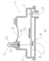
- Fig. 1 is a structural schematic diagram of a first embodiment of a sensor apparatus according to the present invention.
- the sensor apparatus 1 comprises a housing 11, a water temperature sensor unit 12, a water level sensor unit 15, a signal processor unit 16, a printed circuit board 18 and a connector 19.
- the printed circuit board 18 is supported by the housing 11, and the signal processor unit 16 is disposed on the printed circuit board 18.
- the water temperature sensor unit 12 comprises a temperature detector 121 and a protective casing 122.
- the protective casing 122 is fixed to the housing 11, and may be made of a metal material. In the case where the sensor apparatus is installed on a washing machine, the protective casing 122 is oriented so as to face towards the inside of a washing machine drum, and comes into direct contact with water during operation of the washing machine.
- the temperature detector 121 is disposed inside the protective casing 122, and is electrically connected to the signal processor unit 16, so as to transmit detected water temperature signals to the signal processor unit 16.
- the temperature detector 121 may be an NTC temperature detector.
- the water level sensor unit 15 comprises a water pressure detector 151 and a deformation amount detector 152.
- the water pressure detector 151 comprises an elastically deformable device, such as a silicone rubber diaphragm or a metal deformation piece.
- the elastically deformable device is disposed on the housing 11, and in the case where the sensor apparatus is installed on a washing machine, the deformable device can come into direct contact with water, so as to deform due to water pressure.
- the water level height in the washing machine drum changes, the water pressure will change, thereby causing a change in the amount of deformation of the water pressure detector 151.
- the deformation amount detector 152 may be disposed directly on the printed circuit board 18, and can detect the amount of deformation of the water pressure detector 151, and transmit a deformation amount signal of the water pressure detector 151 to the signal processor unit 16. Based on the amount of deformation of the water pressure detector 151, the signal processor unit 16 can obtain a corresponding water level.
- the connector 19 is disposed on the housing 11, and has one end connected to the printed circuit board 18, and another end connected to a control system of the washing machine via an electrical cable, preferably a bus electrical cable, so as to transmit processed digital signals.
- the other end of the connector 19 is provided with a wireless transmission apparatus, to wirelessly transmit digital signals to the control system of the washing machine.
- the water level sensor unit 15 and water temperature sensor unit 12 are disposed on one side of the housing, while the connector 19 is disposed on the other side of the housing which is opposite the water level sensor unit 15.
- the housing comprises a first housing component and a second housing component, which first housing component and second housing component can be fitted together to form a closed unit.
- the first housing component is constructed to have at least two step faces, wherein the water level sensor unit 15 and water temperature sensor unit 12 are installed on the first step face, and the second step face can serve as a mounting face for fixing the sensor apparatus to the water machine.
- the second housing component may be constructed as a cover of the housing.
- the signal processor unit 16 receives water temperature signals and water level signals from the water temperature sensor unit 12 and water level sensor unit 15, subjects the received signals to processing and then conversion to digital signals, and transmits the digital signals to the control system of the washing machine via the connector 19.
- the signal processor unit 16 can subject signals from the water level sensor unit 15 to compensation and correction according to a predetermined algorithm, so as to obtain more precise water level data.
- the water temperature sensor unit 12 and water level sensor unit 15 detect the water temperature and water level height respectively, and send the detected data to the signal processor unit 16.
- the signal processor unit 16 processes the inputted signals, and transmits the processed digital signals to the control system of the washing machine via the connector 19.
- the control system of the washing machine then performs the next operational step according to received parameter values.
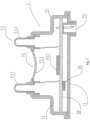
- Fig. 2 is a structural schematic diagram of a second embodiment of a sensor apparatus according to the present invention.
- drawing labels identical to those in the first embodiment are given to elements which have corresponding functions, and a detailed explanation thereof is omitted for the sake of simplicity.
- the sensor apparatus 1 comprises a housing 11, a water level sensor unit 15, a water hardness sensor unit 13, a signal processor unit 16, a printed circuit board 18 and a connector 19.
- the printed circuit board 18 is supported by the housing 11, and the signal processor unit 16 is disposed on the printed circuit board 18.
- the water hardness sensor unit 13 comprises a first electrode 131 and a second electrode 132.
- the first electrode 131 and second electrode 132 are made of an electrically conductive metal material, and fixed to the housing 11.
- the first electrode 131 and second electrode 132 are oriented so as to face towards the inside of the washing machine drum, come into direct contact with water during operation of the washing machine, are electrically connected to the signal processor unit 16, and are used for detecting the electrical conductivity of the water, so as to obtain a water hardness value.
- a water pressure detector 151 is disposed in the middle of a first step face of the housing, and the first electrode and second electrode are disposed on two sides of the water pressure detector 151 respectively, thereby forming a symmetric and compact sensor apparatus structure.
- the number of electrodes is not limited to two; more than two electrodes may be provided.
- the water hardness sensor unit 13 and water level sensor unit 15 detect the water hardness and water level height respectively, and send the detected data to the signal processor unit 16.
- the signal processor unit 16 processes the inputted signals, and transmits the processed digital signals to the control system of the washing machine via the connector 19.
- the control system of the washing machine then performs the next operational step according to received parameter values.
- Fig. 3 is a structural schematic diagram of a third embodiment of a sensor apparatus according to the present invention.
- drawing labels identical to those in the preceding embodiments are given to elements which have corresponding functions, and a detailed explanation thereof is omitted for the sake of simplicity.
- the sensor apparatus 1 comprises a housing 11, a water level sensor unit 15, a load imbalance sensor unit 17, a signal processor unit 16, a printed circuit board 18 and a connector 19.
- the printed circuit board 18 is supported by the housing 11, and the signal processor unit 16 is disposed on the printed circuit board 18.
- the load imbalance sensor unit 17 is disposed on the printed circuit board 18 and electrically connected to the signal processor unit 16.
- the load imbalance sensor unit 17 is used for detecting acceleration and motion of a washing machine outer drum during operation of the washing machine, and sends an obtained parameter value (such as speed, acceleration etc.) associated with motion to the signal processor unit 16, so as to obtain a load imbalance state.
- the load imbalance sensor unit 17 is a MEMS accelerometer.
- the signal processor unit 16 can subject signals from the load imbalance sensor unit 17 to compensation and correction according to a predetermined algorithm, so as to obtain more precise load imbalance state data.
- the load imbalance sensor unit 17 and water level sensor unit 15 detect a washing machine outer drum motion parameter and water level height respectively, and send the detected data to the signal processor unit 16.
- the signal processor unit 16 processes the inputted signals, and transmits the processed digital signals to the control system of the washing machine via the connector 19.
- the control system of the washing machine then performs the next operational step according to received parameter values.
- Fig. 4 is a structural schematic diagram of a fourth embodiment of a sensor apparatus according to the present invention.
- drawing labels identical to those in the preceding embodiments are given to elements which have corresponding functions, and a detailed explanation thereof is omitted for the sake of simplicity.
- the sensor apparatus 1 comprises a housing 11, a water level sensor unit 15, a water turbidity sensor unit 20, a signal processor unit 16, a printed circuit board 18 and a connector 19.
- the printed circuit board 18 is supported by the housing 11, and the signal processor unit 16 is disposed on the printed circuit board 18.
- the water turbidity sensor unit 20 comprises a light emitter 201, a light receiver 202 and protective covers 203.
- the protective covers 203 are disposed on the housing 11.
- the light emitter 201 and light receiver 202 are each located in one protective cover 203, and electrically connected to the signal processor unit 16, and the light emitter 201 and light receiver 202 are arranged to face each other.
- the light emitter 201, light receiver 202 and protective covers 203 are arranged in such a way that a light path of light emitted by the light emitter 201 sequentially passes through the protective cover 203 outside the light emitter 201, the water in the washing machine drum, and the protective cover 203 outside the light receiver 202, and then arrives at the light receiver 202.
- the light emitter 201 emits a certain amount of light, which passes through the protective cover 203 and then propagates through the water in the washing machine drum.
- the light receiver 202 sends the quantity of light received to the signal processor 16, so as to determine the water turbidity according to the size of the quantity of light.
- a water pressure detector 151 is disposed in the middle of a first step face of the housing, and the light emitter 201 and light receiver 202 are disposed on two sides of the water pressure detector 151 respectively, thereby forming a symmetric and compact sensor apparatus structure.
- the water turbidity sensor unit there is no restriction to one light emitter/light receiver pair; two or more light emitter/light receiver pairs may be provided according to measurement precision requirements.
- the protective covers which accommodate the light emitter and light receiver may be transparent, translucent or opaque.
- the protective covers might be translucent or opaque to the human eye.
- the protective covers may be installed on the housing as independent components, or made integrally with the housing.
- the water turbidity sensor unit 20 and water level sensor unit 15 detect water turbidity and water level height respectively, and send the detected data to the signal processor unit 16.
- the signal processor unit 16 processes the inputted signals, and transmits the processed digital signals to the control system of the washing machine via the connector 19.
- the control system of the washing machine then performs the next operational step according to received parameter values.
- Fig. 5 is a structural schematic diagram of a fifth embodiment of a sensor apparatus according to the present invention.
- drawing labels identical to those in the preceding embodiments are given to elements which have corresponding functions, and a detailed explanation thereof is omitted for the sake of simplicity.
- the sensor apparatus 1 comprises a housing 11, a water level sensor unit 15, a water temperature sensor unit 12, a water hardness sensor unit 13, a load imbalance sensor unit 17, a signal processor unit 16, a printed circuit board 18 and a connector 19.
- the printed circuit board 18 is supported by the housing 11, and the signal processor unit 16 is disposed on the printed circuit board 18.
- the water temperature sensor unit 12 is not provided with a protective casing for a temperature detector 121. Instead, a first electrode 131 of the water hardness sensor unit 13 performs the function of protecting the temperature detector 121. While detecting the electrical conductivity of the water, the first electrode 131 protects the temperature detector 121 from contact with water and transmits water heat to the temperature detector 121. Through such an arrangement, the number of components in the sensor apparatus is further reduced, thereby forming a compact sensor apparatus structure.
- the signal processor unit 16 can subject signals from the water hardness sensor unit 13 and load imbalance sensor unit 17 to compensation and correction according to a predetermined algorithm, so as to obtain more precise water hardness and load imbalance states.
- the water level sensor unit 15, water temperature sensor unit 12, water hardness sensor unit 13 and load imbalance sensor unit 17 detect water level height, water temperature, water hardness, and washing machine outer drum motion parameters respectively, and send the detected data to the signal processor unit 16.
- the signal processor unit 16 processes the inputted signals, and transmits the processed digital signals to the control system of the washing machine via the connector 19. The control system of the washing machine then performs the next operational step according to received parameter values.
- Fig. 6 is a structural schematic diagram of a sixth embodiment of a sensor apparatus according to the present invention.
- drawing labels identical to those in the preceding embodiments are given to elements which have corresponding functions, and a detailed explanation thereof is omitted for the sake of simplicity.
- the sensor apparatus 1 comprises a housing 11, a water level sensor unit 15, a water temperature sensor unit 12, a water hardness sensor unit 13, a load imbalance sensor unit 17, a signal processor unit 16, a printed circuit board 18 and a connector 19.
- the printed circuit board 18 is supported by the housing 11, and the signal processor unit 16 is disposed on the printed circuit board 18.
- the sixth embodiment of the sensor apparatus differs from the fifth embodiment in the construction of the water level sensor unit 15.
- the water level sensor unit 15 comprises a water pressure detector 151", a spring deformation amount detector 152" and a spring 153".
- the water pressure detector 151" is disposed on the housing 11, with two ends fixed to the housing 11, and can freely extend and retract and transmit water pressure to the spring 153".
- the water pressure detector 151" is a bellows structure with a bottom.
- the water pressure detector 151" can seal the sensor, preventing water from seeping into the interior of the sensor.
- the spring 153" has one end fixed to the bottom of the water pressure detector 151", and another end fixed to the printed circuit board 18.
- the spring 153" can move in reciprocal motion between the water pressure detector 151" and the printed circuit board 18, extending or retracting with changes in water pressure.
- the spring deformation amount detector 152" is disposed on the printed circuit board 18 and electrically connected to the signal processor unit 16.
- the spring deformation amount detector 152" detects the amount of deformation of the spring 153, and transmits a deformation amount signal of the spring 153 to the signal processor unit 16.
- the signal processor unit 16 converts the deformation amount of the spring to a water level height, then outputs a processed digital signal to the control system of the washing machine via the connector 19.
- the signal processor unit 16 can not only compensate and correct other parameters according to water temperature and water level data, but can also compensate and correct other parameters according to drum position and load weight data, etc.
- Fig. 9 shows schematically an example of a diagram showing signal compensation relationships among various processing parameters. It can be seen from Fig. 9 that the signal processor unit can compensate various parameters of water level, drum position, load weight, load imbalance state, water turbidity and water hardness according to water temperature data, compensate a load imbalance state parameter according to water level data, compensate water level and load weight according to drum position data, and compensate drum position according to load weight data.
- the present invention is not limited to the example of the signal compensation relationships in Fig. 9 .
- the sensor apparatus of the present invention comprises a greater or smaller number of sensor units, similar compensation relationships exist among the various parameters. More precise measurements can thereby be achieved.
- Fig. 7 is a structural schematic diagram of a first embodiment of a washing machine according to the present invention.
- the washing machine of the present invention has the same components as a conventional washing machine (such as water intake system, water drainage system, etc.). These identical components are not described further here; only those features of the washing machine of the present invention which differ from a conventional washing machine are described.
- a sensor apparatus 1 of the present invention is installed at an opening in the bottom of a washing machine outer drum 2, and is fixed by, for example, a screw-thread connection or an adhesive connection, etc.
- the sensor apparatus 1 comes into direct contact with water in the washing machine outer drum, such that the various sensor units detect relevant parameters, and send signals to the signal processor unit, followed by transmission to the control system of the washing machine, to ensure normal operation of the washing machine.
- the sensor apparatus 1 is installed at the bottom of the washing machine outer drum; this is very beneficial for measurement of water level height.
- the present invention combines various sensor elements in the housing 11 in an integrated manner to form the sensor apparatus 1, thereby simplifying the installation steps and internal structure of the washing machine, shortening the installation time, and reducing the use of electrical cables and connectors, thereby reducing installation costs.
- various processing parameters of the washing machine can be detected more precisely.
- Fig. 8 is a structural schematic diagram of a second embodiment of a washing machine according to the present invention.
- the sensor apparatus 1 is not installed at an opening in the bottom of a washing machine outer drum 2, but is installed on a connecting hose 3 (which connects the outer drum to a water drainage apparatus) of the washing machine outer drum, in a position close to the bottom of the washing machine outer drum.
- the sensor apparatus 1 comes into contact with water in the connecting hose 3, in order to detect relevant signals.
- Such an arrangement can not only achieve the same technical effects and advantages as the washing machine in Fig. 7 , but since there is no need to additionally provide an opening for the sensor apparatus 1 in the outer drum 2 of the washing machine, a forming mould for the outer drum 2 is kept unchanged, and application in an existing washing machine is easy; compared with the washing machine in Fig. 7 , manufacturing costs are vastly reduced.
- the orientation of the sensor apparatus may be vertical, or inclined relative to a vertical direction.
- the electrical appliance used for washing may be a dishwasher, with the sensor apparatus installed at the bottom, or at the bottom of one side, of an inner chamber of the dishwasher, or installed on a connecting apparatus (which connects the inner chamber to a water drainage apparatus) of the dishwasher.
Landscapes
- Engineering & Computer Science (AREA)
- Textile Engineering (AREA)
- Physics & Mathematics (AREA)
- General Physics & Mathematics (AREA)
- Control Of Washing Machine And Dryer (AREA)
Claims (14)
- Appareil de détection, pouvant être utilisé pour détecter au moins deux paramètres de traitement d'un appareil électrique utilisé pour le lavage, l'appareil de détection (1) comprenant :au moins deux unités de détection, utilisées pour détecter des paramètres de traitement différents ;une unité de traitement des signaux (16), connectée électriquement aux au moins deux unités de détection, qui acquiert et traite les signaux provenant des au moins deux unités de détection et délivre en sortie des signaux numériques ;un boîtier (11), qui accueille les au moins deux unités de détection et l'unité de traitement des signaux (16), où :les au moins deux unités de détection comprennent une unité de détection de niveau d'eau (15),caractérisé par le fait que l'unité de détection de niveau d'eau (15) comprend un détecteur de pression d'eau (151, 151') et un détecteur de quantité de déformation (152), le détecteur de pression d'eau (151, 151') comprenant un dispositif déformable qui se déforme en raison de la pression d'eau qui lui est appliquée, le détecteur de quantité de déformation (152) étant capable de détecter une quantité de déformation du dispositif déformable et d'envoyer un signal de quantité de déformation à l'unité de traitement des signaux (16).
- Appareil de détection selon la revendication 1, caractérisé par le fait qu'en plus de l'unité de détection de niveau d'eau (15), l'autre des au moins deux unités de détection comprend une ou plusieurs des unités de détection suivantes : une unité de détection de la température de l'eau (12), une unité de détection de la dureté de l'eau (13), une unité de détection de la turbidité de l'eau (20), une unité de détection de la position du tambour, une unité de détection du poids de la charge et une unité de détection du déséquilibre de la charge (17).
- Appareil de détection selon la revendication 1 ou la revendication 2, caractérisé par le fait que le dispositif déformable est un diaphragme déformable.
- Appareil de détection selon l'une des revendications précédentes, caractérisé par le fait que l'unité de détection de niveau d'eau (15) comprend un détecteur de pression d'eau (151, 151'), un ressort (153") et un détecteur de quantité de déformation du ressort (152"), où le détecteur de pression d'eau (151, 151') transmet la pression d'eau au ressort (153"), le ressort (153") se déforme sous l'effet de la pression d'eau, et le détecteur de quantité de déformation du ressort (152") peut détecter une quantité de déformation du ressort (153"), et envoyer un signal de quantité de déformation à l'unité de traitement des signaux (16).
- Appareil de détection selon l'une des revendications précédentes, caractérisé par le fait qu'en plus de l'unité de détection de niveau d'eau (15), l'autre des au moins deux unités de détection comprend une unité de détection de la dureté de l'eau (13), l'unité de détection de la dureté de l'eau (13) comprenant au moins deux électrodes (131, 132), les au moins deux électrodes (131, 132) étant constituées d'un matériau conducteur d'électricité et orientées vers une zone située à l'extérieur du boîtier (11), et étant utilisées pour détecter la conductivité électrique de l'eau.
- Appareil de détection selon l'une des revendications précédentes, caractérisé par le fait qu'en plus de l'unité de détection de niveau d'eau (15), l'autre des au moins deux unités de détection comprend une unité de détection de la température de l'eau (12), l'unité de détection de la température de l'eau (12) comprenant un détecteur de température (121) et un coffret de protection (122), le coffret de protection (122) étant fixé au boîtier (11) et orienté vers une zone située à l'extérieur du boîtier (11), le détecteur de température (121) étant disposé à l'intérieur du coffret de protection (122).
- Appareil de détection selon l'une des revendications précédentes, caractérisé par le fait qu'en plus de l'unité de détection de niveau d'eau (15), l'autre des au moins deux unités de détection comprend une unité de détection du déséquilibre de la charge (17), l'unité de détection du déséquilibre de la charge (17) détectant l'accélération et le mouvement d'un composant mobile chargé de l'appareil électrique, et envoyant à l'unité de traitement des signaux (16) une valeur obtenue d'un paramètre lié au mouvement.
- Appareil de détection selon l'une des revendications précédentes, caractérisé par le fait qu'en plus de l'unité de détection de niveau d'eau (15), l'autre des au moins deux unités de détection comprend une unité de détection de la turbidité de l'eau (20), l'unité de détection de la turbidité de l'eau (20) comprenant un émetteur de lumière, un récepteur de lumière (202) et des capots de protection (203), où l'émetteur de lumière (201) et le récepteur de lumière (202) sont chacun situés dans un capot de protection (203), et l'émetteur de lumière (201), le récepteur de lumière (202) et les capots de protection (203) sont agencés de telle sorte que la lumière émise par l'émetteur de lumière (201) passe séquentiellement à travers le capot de protection (203) accueillant l'émetteur de lumière (201), l'eau, et le capot de protection accueillant le récepteur de lumière (202), et arrive ensuite au récepteur de lumière (202) .
- Appareil de détection selon l'une des revendications précédentes, caractérisé par le fait qu'en plus de l'unité de détection de niveau d'eau (15), l'autre des au moins deux unités de détection comprend une unité de détection de la température de l'eau (12) et une unité de détection de la dureté de l'eau (13), l'unité de détection de la dureté de l'eau (13) comprenant au moins deux électrodes (131, 132), où les au moins deux électrodes (131, 132) sont fixées au boîtier (11), sont constituées d'un matériau conducteur d'électricité et sont orientées vers une zone située à l'extérieur du boîtier (11), et peuvent détecter la conductivité électrique de l'eau, et l'unité de détection de la température de l'eau (12) comprend un détecteur de température (121) disposé à l'intérieur de l'une des au moins deux électrodes (131, 132).
- Appareil de détection selon l'une des revendications précédentes, caractérisé par le fait que l'unité de traitement des signaux (16) délivre en sortie des signaux numériques à un système de commande de l'appareil électrique de manière câblée ou sans fil au moyen d'un connecteur (19).
- Appareil de détection selon l'une des revendications précédentes, caractérisé par le fait que l'unité de traitement des signaux (16) est capable, sur la base d'un signal provenant de l'une des au moins deux unités de détection, de compenser un signal d'une ou de plusieurs autres des au moins deux unités de détection.
- Appareil électrique utilisé pour le lavage, notamment un lave-linge ou un lave-vaisselle, comprenant l'appareil de détection (1) selon l'une quelconque des revendications 1 - 11.
- Appareil électrique selon la revendication 12, caractérisé par le fait que l'appareil de détection (1) est installé au fond, ou au fond d'un côté, d'un tambour extérieur (2) du lave-linge ou que l'appareil de détection (1) est installé au fond, ou au fond d'un côté, d'une chambre intérieure du lave-vaisselle.
- Appareil électrique selon la revendication 12 ou 13, caractérisé par le fait que l'appareil de détection (1) est installé sur un appareil de raccordement, reliant le tambour extérieur (2) à un appareil d'évacuation de l'eau, du lave-linge, à une position proche du fond du tambour extérieur (2) du lave-linge ou que l'appareil de détection (1) est installé sur un appareil de raccordement, reliant la chambre intérieure à un appareil d'évacuation de l'eau, du lave-vaisselle.
Applications Claiming Priority (1)
| Application Number | Priority Date | Filing Date | Title |
|---|---|---|---|
| CN201610642993.1A CN107692944A (zh) | 2016-08-08 | 2016-08-08 | 传感器装置和设有该传感器装置的用于洗涤的电器 |
Publications (2)
| Publication Number | Publication Date |
|---|---|
| EP3290571A1 EP3290571A1 (fr) | 2018-03-07 |
| EP3290571B1 true EP3290571B1 (fr) | 2025-01-01 |
Family
ID=59387866
Family Applications (1)
| Application Number | Title | Priority Date | Filing Date |
|---|---|---|---|
| EP17001251.2A Active EP3290571B1 (fr) | 2016-08-08 | 2017-07-21 | Appareil de détection et appareil électrique utilisé pour le lavage et équipé dudit appareil de détection |
Country Status (2)
| Country | Link |
|---|---|
| EP (1) | EP3290571B1 (fr) |
| CN (1) | CN107692944A (fr) |
Families Citing this family (8)
| Publication number | Priority date | Publication date | Assignee | Title |
|---|---|---|---|---|
| EP3802941B1 (fr) * | 2018-05-25 | 2025-05-21 | Electrolux Professional AB (publ) | Machine à laver |
| CN110353592B (zh) * | 2019-07-24 | 2024-07-19 | 佛山市百斯特电器科技有限公司 | 一种家用电器设备 |
| DE102019007379A1 (de) * | 2019-10-23 | 2021-04-29 | Emz-Hanauer Gmbh & Co. Kgaa | Sensor zum Einbau in ein elektrisches Haushaltsgerät |
| CN111593533A (zh) * | 2020-05-30 | 2020-08-28 | 广东蓝水花智能电子有限公司 | 洗衣机用检测传感器安装方法及洗衣机用检测传感器 |
| CN115406867A (zh) * | 2021-05-26 | 2022-11-29 | 常德思高技术有限公司 | 一种集成温度检测的浊度传感器 |
| CN114271753B (zh) * | 2021-12-17 | 2023-08-25 | 华帝股份有限公司 | 洗碗机洗涤方法和洗碗机 |
| US12392070B2 (en) * | 2022-09-29 | 2025-08-19 | Haier Us Appliance Solutions, Inc. | Systems and methods for drain pump operation in washing machine appliances |
| DE102023207596A1 (de) * | 2023-08-08 | 2025-02-13 | BSH Hausgeräte GmbH | Digitaler Sensor und Wäschepflegegerät mit einem digitalen Sensor |
Citations (1)
| Publication number | Priority date | Publication date | Assignee | Title |
|---|---|---|---|---|
| KR101471942B1 (ko) * | 2013-09-03 | 2014-12-11 | 에이에스텍 주식회사 | 세탁기용 수위 감지센서 |
Family Cites Families (10)
| Publication number | Priority date | Publication date | Assignee | Title |
|---|---|---|---|---|
| US5444531A (en) * | 1994-05-20 | 1995-08-22 | Honeywell Inc. | Sensor with led current control for use in machines for washing articles |
| KR19990042143A (ko) * | 1997-11-25 | 1999-06-15 | 윤종용 | 세탁기의 수위조절 장치 및 제어방법 |
| DE19821148A1 (de) * | 1998-05-12 | 1999-11-18 | Aeg Hausgeraete Gmbh | Programmgesteuertes wasserführendes elektrisches Haushaltsgerät |
| DE50210345D1 (de) * | 2002-01-31 | 2007-08-02 | Emz Hanauer Gmbh & Co Kgaa | Trübungssensor mit Temperaturerfassung für Haushaltsgeräte |
| DE102007016215A1 (de) * | 2006-04-08 | 2007-10-11 | Marquardt Gmbh | Sensor zur Trübungs- und Temperaturmessung |
| IT1392256B1 (it) * | 2008-12-05 | 2012-02-22 | Illinois Tool Works | Sensore di pressione modificato per rilevare parametri operativi di un elettrodomestico dotato di un componente relativamente mobile |
| CN102926166A (zh) * | 2011-08-10 | 2013-02-13 | 苏州三星电子有限公司 | 洗衣机及减小洗衣机振动损害的方法 |
| CN102634960A (zh) * | 2012-03-28 | 2012-08-15 | 海尔集团公司 | 洗衣机的传感装置和洗衣机及其控制方法 |
| EP2767631B1 (fr) | 2013-02-15 | 2017-05-17 | Electrolux Appliances Aktiebolag | Machine à laver avec dispositif de détection de niveau amélioré |
| CN104947371B (zh) * | 2015-05-27 | 2017-03-01 | 厦门翰普电子有限公司 | 一种基于mems传感器检测洗衣机振动位移数据的方法 |
-
2016
- 2016-08-08 CN CN201610642993.1A patent/CN107692944A/zh active Pending
-
2017
- 2017-07-21 EP EP17001251.2A patent/EP3290571B1/fr active Active
Patent Citations (1)
| Publication number | Priority date | Publication date | Assignee | Title |
|---|---|---|---|---|
| KR101471942B1 (ko) * | 2013-09-03 | 2014-12-11 | 에이에스텍 주식회사 | 세탁기용 수위 감지센서 |
Also Published As
| Publication number | Publication date |
|---|---|
| CN107692944A (zh) | 2018-02-16 |
| EP3290571A1 (fr) | 2018-03-07 |
Similar Documents
| Publication | Publication Date | Title |
|---|---|---|
| EP3290571B1 (fr) | Appareil de détection et appareil électrique utilisé pour le lavage et équipé dudit appareil de détection | |
| US7159464B2 (en) | Pressure sensor | |
| EA016379B1 (ru) | Устройство и способ определения уровня заполнения бака стиральной машины | |
| US20140232418A1 (en) | Measuring Device and Method for the Detection of an Approach | |
| GB2490452A (en) | Integrated part temperature measurement system | |
| ITTO20080904A1 (it) | Sensore di pressione modificato per rilevare parametri operativi di un elettrodomestico dotato di un componente relativamente mobile | |
| KR20100102537A (ko) | 근접센서 및 회전조작검출장치 | |
| CN110907073A (zh) | 触觉传感器 | |
| CN114184311B (zh) | 触觉传感器 | |
| CN104283541B (zh) | 传感器装置和用于运行操作装置的方法 | |
| JP6626619B2 (ja) | センサモジュールおよびセンシング装置 | |
| US20250333296A1 (en) | Mems sensor device and sensing method | |
| US12306030B2 (en) | Sensor assembly | |
| CN111361114A (zh) | 感测模块 | |
| CN116105787A (zh) | 传感器模组 | |
| CN106050943B (zh) | 具有振动传感器的带罩盖轴承 | |
| KR102615446B1 (ko) | 온도 이상 검출 장치 | |
| JP2005195435A (ja) | 非接触型温度検出器 | |
| EP3665448B1 (fr) | Dispositif de détermination de charge et procédé de fabrication correspondant | |
| CN215005827U (zh) | 磁场感测装置 | |
| CN215262076U (zh) | 用于红外热像仪的温度校正结构及红外热像仪 | |
| JP2010008322A (ja) | 回転検出装置 | |
| CN116147822B (zh) | 压力传感器 | |
| JP2015190897A (ja) | 赤外線センサ装置 | |
| CN219977454U (zh) | 一种温湿度传感器 |
Legal Events
| Date | Code | Title | Description |
|---|---|---|---|
| PUAI | Public reference made under article 153(3) epc to a published international application that has entered the european phase |
Free format text: ORIGINAL CODE: 0009012 |
|
| STAA | Information on the status of an ep patent application or granted ep patent |
Free format text: STATUS: THE APPLICATION HAS BEEN PUBLISHED |
|
| AK | Designated contracting states |
Kind code of ref document: A1 Designated state(s): AL AT BE BG CH CY CZ DE DK EE ES FI FR GB GR HR HU IE IS IT LI LT LU LV MC MK MT NL NO PL PT RO RS SE SI SK SM TR |
|
| AX | Request for extension of the european patent |
Extension state: BA ME |
|
| RIN1 | Information on inventor provided before grant (corrected) |
Inventor name: LI, ZHONGKE Inventor name: LI, YAN |
|
| STAA | Information on the status of an ep patent application or granted ep patent |
Free format text: STATUS: REQUEST FOR EXAMINATION WAS MADE |
|
| 17P | Request for examination filed |
Effective date: 20180525 |
|
| RBV | Designated contracting states (corrected) |
Designated state(s): AL AT BE BG CH CY CZ DE DK EE ES FI FR GB GR HR HU IE IS IT LI LT LU LV MC MK MT NL NO PL PT RO RS SE SI SK SM TR |
|
| STAA | Information on the status of an ep patent application or granted ep patent |
Free format text: STATUS: EXAMINATION IS IN PROGRESS |
|
| 17Q | First examination report despatched |
Effective date: 20190115 |
|
| GRAP | Despatch of communication of intention to grant a patent |
Free format text: ORIGINAL CODE: EPIDOSNIGR1 |
|
| STAA | Information on the status of an ep patent application or granted ep patent |
Free format text: STATUS: GRANT OF PATENT IS INTENDED |
|
| INTG | Intention to grant announced |
Effective date: 20240813 |
|
| GRAS | Grant fee paid |
Free format text: ORIGINAL CODE: EPIDOSNIGR3 |
|
| GRAA | (expected) grant |
Free format text: ORIGINAL CODE: 0009210 |
|
| STAA | Information on the status of an ep patent application or granted ep patent |
Free format text: STATUS: THE PATENT HAS BEEN GRANTED |
|
| AK | Designated contracting states |
Kind code of ref document: B1 Designated state(s): AL AT BE BG CH CY CZ DE DK EE ES FI FR GB GR HR HU IE IS IT LI LT LU LV MC MK MT NL NO PL PT RO RS SE SI SK SM TR |
|
| REG | Reference to a national code |
Ref country code: GB Ref legal event code: FG4D |
|
| REG | Reference to a national code |
Ref country code: DE Ref legal event code: R096 Ref document number: 602017087044 Country of ref document: DE |
|
| REG | Reference to a national code |
Ref country code: CH Ref legal event code: EP |
|
| REG | Reference to a national code |
Ref country code: IE Ref legal event code: FG4D |
|
| REG | Reference to a national code |
Ref country code: LT Ref legal event code: MG9D |
|
| REG | Reference to a national code |
Ref country code: NL Ref legal event code: MP Effective date: 20250101 |
|
| REG | Reference to a national code |
Ref country code: AT Ref legal event code: MK05 Ref document number: 1756338 Country of ref document: AT Kind code of ref document: T Effective date: 20250101 |
|
| PG25 | Lapsed in a contracting state [announced via postgrant information from national office to epo] |
Ref country code: NL Free format text: LAPSE BECAUSE OF FAILURE TO SUBMIT A TRANSLATION OF THE DESCRIPTION OR TO PAY THE FEE WITHIN THE PRESCRIBED TIME-LIMIT Effective date: 20250101 |
|
| PG25 | Lapsed in a contracting state [announced via postgrant information from national office to epo] |
Ref country code: FI Free format text: LAPSE BECAUSE OF FAILURE TO SUBMIT A TRANSLATION OF THE DESCRIPTION OR TO PAY THE FEE WITHIN THE PRESCRIBED TIME-LIMIT Effective date: 20250101 |
|
| PG25 | Lapsed in a contracting state [announced via postgrant information from national office to epo] |
Ref country code: PL Free format text: LAPSE BECAUSE OF FAILURE TO SUBMIT A TRANSLATION OF THE DESCRIPTION OR TO PAY THE FEE WITHIN THE PRESCRIBED TIME-LIMIT Effective date: 20250101 |
|
| PG25 | Lapsed in a contracting state [announced via postgrant information from national office to epo] |
Ref country code: ES Free format text: LAPSE BECAUSE OF FAILURE TO SUBMIT A TRANSLATION OF THE DESCRIPTION OR TO PAY THE FEE WITHIN THE PRESCRIBED TIME-LIMIT Effective date: 20250101 |
|
| PG25 | Lapsed in a contracting state [announced via postgrant information from national office to epo] |
Ref country code: NO Free format text: LAPSE BECAUSE OF FAILURE TO SUBMIT A TRANSLATION OF THE DESCRIPTION OR TO PAY THE FEE WITHIN THE PRESCRIBED TIME-LIMIT Effective date: 20250401 Ref country code: IS Free format text: LAPSE BECAUSE OF FAILURE TO SUBMIT A TRANSLATION OF THE DESCRIPTION OR TO PAY THE FEE WITHIN THE PRESCRIBED TIME-LIMIT Effective date: 20250501 |
|
| PG25 | Lapsed in a contracting state [announced via postgrant information from national office to epo] |
Ref country code: HR Free format text: LAPSE BECAUSE OF FAILURE TO SUBMIT A TRANSLATION OF THE DESCRIPTION OR TO PAY THE FEE WITHIN THE PRESCRIBED TIME-LIMIT Effective date: 20250101 |
|
| PG25 | Lapsed in a contracting state [announced via postgrant information from national office to epo] |
Ref country code: LV Free format text: LAPSE BECAUSE OF FAILURE TO SUBMIT A TRANSLATION OF THE DESCRIPTION OR TO PAY THE FEE WITHIN THE PRESCRIBED TIME-LIMIT Effective date: 20250101 Ref country code: PT Free format text: LAPSE BECAUSE OF FAILURE TO SUBMIT A TRANSLATION OF THE DESCRIPTION OR TO PAY THE FEE WITHIN THE PRESCRIBED TIME-LIMIT Effective date: 20250502 |
|
| PG25 | Lapsed in a contracting state [announced via postgrant information from national office to epo] |
Ref country code: GR Free format text: LAPSE BECAUSE OF FAILURE TO SUBMIT A TRANSLATION OF THE DESCRIPTION OR TO PAY THE FEE WITHIN THE PRESCRIBED TIME-LIMIT Effective date: 20250402 Ref country code: BG Free format text: LAPSE BECAUSE OF FAILURE TO SUBMIT A TRANSLATION OF THE DESCRIPTION OR TO PAY THE FEE WITHIN THE PRESCRIBED TIME-LIMIT Effective date: 20250101 |
|
| PG25 | Lapsed in a contracting state [announced via postgrant information from national office to epo] |
Ref country code: AT Free format text: LAPSE BECAUSE OF FAILURE TO SUBMIT A TRANSLATION OF THE DESCRIPTION OR TO PAY THE FEE WITHIN THE PRESCRIBED TIME-LIMIT Effective date: 20250101 |
|
| PG25 | Lapsed in a contracting state [announced via postgrant information from national office to epo] |
Ref country code: CZ Free format text: LAPSE BECAUSE OF FAILURE TO SUBMIT A TRANSLATION OF THE DESCRIPTION OR TO PAY THE FEE WITHIN THE PRESCRIBED TIME-LIMIT Effective date: 20250101 |
|
| PG25 | Lapsed in a contracting state [announced via postgrant information from national office to epo] |
Ref country code: SE Free format text: LAPSE BECAUSE OF FAILURE TO SUBMIT A TRANSLATION OF THE DESCRIPTION OR TO PAY THE FEE WITHIN THE PRESCRIBED TIME-LIMIT Effective date: 20250101 |
|
| REG | Reference to a national code |
Ref country code: DE Ref legal event code: R097 Ref document number: 602017087044 Country of ref document: DE |
|
| PG25 | Lapsed in a contracting state [announced via postgrant information from national office to epo] |
Ref country code: SM Free format text: LAPSE BECAUSE OF FAILURE TO SUBMIT A TRANSLATION OF THE DESCRIPTION OR TO PAY THE FEE WITHIN THE PRESCRIBED TIME-LIMIT Effective date: 20250101 |
|
| PG25 | Lapsed in a contracting state [announced via postgrant information from national office to epo] |
Ref country code: DK Free format text: LAPSE BECAUSE OF FAILURE TO SUBMIT A TRANSLATION OF THE DESCRIPTION OR TO PAY THE FEE WITHIN THE PRESCRIBED TIME-LIMIT Effective date: 20250101 |
|
| PGFP | Annual fee paid to national office [announced via postgrant information from national office to epo] |
Ref country code: DE Payment date: 20250904 Year of fee payment: 9 |
|
| PG25 | Lapsed in a contracting state [announced via postgrant information from national office to epo] |
Ref country code: IT Free format text: LAPSE BECAUSE OF FAILURE TO SUBMIT A TRANSLATION OF THE DESCRIPTION OR TO PAY THE FEE WITHIN THE PRESCRIBED TIME-LIMIT Effective date: 20250101 |
|
| PG25 | Lapsed in a contracting state [announced via postgrant information from national office to epo] |
Ref country code: EE Free format text: LAPSE BECAUSE OF FAILURE TO SUBMIT A TRANSLATION OF THE DESCRIPTION OR TO PAY THE FEE WITHIN THE PRESCRIBED TIME-LIMIT Effective date: 20250101 |
|
| PG25 | Lapsed in a contracting state [announced via postgrant information from national office to epo] |
Ref country code: RO Free format text: LAPSE BECAUSE OF FAILURE TO SUBMIT A TRANSLATION OF THE DESCRIPTION OR TO PAY THE FEE WITHIN THE PRESCRIBED TIME-LIMIT Effective date: 20250101 |
|
| PG25 | Lapsed in a contracting state [announced via postgrant information from national office to epo] |
Ref country code: SK Free format text: LAPSE BECAUSE OF FAILURE TO SUBMIT A TRANSLATION OF THE DESCRIPTION OR TO PAY THE FEE WITHIN THE PRESCRIBED TIME-LIMIT Effective date: 20250101 |
|
| PLBE | No opposition filed within time limit |
Free format text: ORIGINAL CODE: 0009261 |
|
| STAA | Information on the status of an ep patent application or granted ep patent |
Free format text: STATUS: NO OPPOSITION FILED WITHIN TIME LIMIT |
|
| REG | Reference to a national code |
Ref country code: CH Ref legal event code: L10 Free format text: ST27 STATUS EVENT CODE: U-0-0-L10-L00 (AS PROVIDED BY THE NATIONAL OFFICE) Effective date: 20251112 |
|
| 26N | No opposition filed |
Effective date: 20251002 |
|
| REG | Reference to a national code |
Ref country code: CH Ref legal event code: H13 Free format text: ST27 STATUS EVENT CODE: U-0-0-H10-H13 (AS PROVIDED BY THE NATIONAL OFFICE) Effective date: 20260224 |
|
| PG25 | Lapsed in a contracting state [announced via postgrant information from national office to epo] |
Ref country code: LU Free format text: LAPSE BECAUSE OF NON-PAYMENT OF DUE FEES Effective date: 20250721 |
|
| GBPC | Gb: european patent ceased through non-payment of renewal fee |
Effective date: 20250721 |
|
| REG | Reference to a national code |
Ref country code: BE Ref legal event code: MM Effective date: 20250731 |
|
| PG25 | Lapsed in a contracting state [announced via postgrant information from national office to epo] |
Ref country code: GB Free format text: LAPSE BECAUSE OF NON-PAYMENT OF DUE FEES Effective date: 20250721 |
|
| PG25 | Lapsed in a contracting state [announced via postgrant information from national office to epo] |
Ref country code: BE Free format text: LAPSE BECAUSE OF NON-PAYMENT OF DUE FEES Effective date: 20250731 |
|
| PG25 | Lapsed in a contracting state [announced via postgrant information from national office to epo] |
Ref country code: FR Free format text: LAPSE BECAUSE OF NON-PAYMENT OF DUE FEES Effective date: 20250731 |
|
| PG25 | Lapsed in a contracting state [announced via postgrant information from national office to epo] |
Ref country code: CH Free format text: LAPSE BECAUSE OF NON-PAYMENT OF DUE FEES Effective date: 20250731 |