EP3290371A1 - Clearing-limit setting device and yarn winding machine - Google Patents
Clearing-limit setting device and yarn winding machine Download PDFInfo
- Publication number
- EP3290371A1 EP3290371A1 EP17186623.9A EP17186623A EP3290371A1 EP 3290371 A1 EP3290371 A1 EP 3290371A1 EP 17186623 A EP17186623 A EP 17186623A EP 3290371 A1 EP3290371 A1 EP 3290371A1
- Authority
- EP
- European Patent Office
- Prior art keywords
- clearing
- yarn
- limit
- section
- display
- Prior art date
- Legal status (The legal status is an assumption and is not a legal conclusion. Google has not performed a legal analysis and makes no representation as to the accuracy of the status listed.)
- Withdrawn
Links
Images






Classifications
-
- D—TEXTILES; PAPER
- D06—TREATMENT OF TEXTILES OR THE LIKE; LAUNDERING; FLEXIBLE MATERIALS NOT OTHERWISE PROVIDED FOR
- D06H—MARKING, INSPECTING, SEAMING OR SEVERING TEXTILE MATERIALS
- D06H3/00—Inspecting textile materials
-
- B—PERFORMING OPERATIONS; TRANSPORTING
- B65—CONVEYING; PACKING; STORING; HANDLING THIN OR FILAMENTARY MATERIAL
- B65H—HANDLING THIN OR FILAMENTARY MATERIAL, e.g. SHEETS, WEBS, CABLES
- B65H63/00—Warning or safety devices, e.g. automatic fault detectors, stop-motions ; Quality control of the package
- B65H63/06—Warning or safety devices, e.g. automatic fault detectors, stop-motions ; Quality control of the package responsive to presence of irregularities in running material, e.g. for severing the material at irregularities ; Control of the correct working of the yarn cleaner
-
- D—TEXTILES; PAPER
- D01—NATURAL OR MAN-MADE THREADS OR FIBRES; SPINNING
- D01H—SPINNING OR TWISTING
- D01H13/00—Other common constructional features, details or accessories
- D01H13/14—Warning or safety devices, e.g. automatic fault detectors, stop motions ; Monitoring the entanglement of slivers in drafting arrangements
- D01H13/22—Warning or safety devices, e.g. automatic fault detectors, stop motions ; Monitoring the entanglement of slivers in drafting arrangements responsive to presence of irregularities in running material
-
- D—TEXTILES; PAPER
- D01—NATURAL OR MAN-MADE THREADS OR FIBRES; SPINNING
- D01H—SPINNING OR TWISTING
- D01H13/00—Other common constructional features, details or accessories
- D01H13/32—Counting, measuring, recording or registering devices
Definitions
- the present disclosure relates to a clearing-limit setting device and a yarn winding machine.
- a machine control device of an air spinning machine may have a function of displaying a clearing limit that is a borderline whether a yarn defect needs to be removed in a two-dimensional field having coordinate axes respectively representing the length and the thickness of a yarn defect (see Japanese Unexamined Patent Publication No. 2007-211363 , for example).
- the present disclosure aims to provide a clearing-limit setting device and a yarn winding machine that can easily and appropriately change at least one portion of a clearing limit.
- a clearing-limit setting device includes: a display unit that displays, in a two-dimensional field having coordinate axes respectively representing length and thickness of a yarn defect, a clearing limit that is a borderline whether the yarn defect needs to be removed; a first input section that receives selection of at least one portion of the clearing limit; a second input section that indicates a plurality of moving directions for the clearing limit and receives selection of a moving direction thereamong; and a processor that changes the clearing limit such that the at least one portion selected with the first input section moves in the moving direction selected with the second input section by a predetermined amount, and causes the display unit to display the clearing limit changed.
- At least one portion of the clearing limit can be selected, and the at least one portion selected can be moved.
- the second input section that moves the at least one portion selected indicates the moving directions for the clearing limit. This allows an operator to intuitively move the at least one portion selected in a desired moving direction with the second input section. Thus, with this clearing-limit setting device, at least one portion of the clearing limit can be easily and appropriately changed.
- the first input section may include the clearing limit displayed by the display unit and receive selection of at least one portion that has been touched in the clearing limit. This allows the operator to easily select a desired portion in the clearing limit.
- the processor may cause the display unit to display the at least one portion selected with the first input section such that the at least one portion becomes identifiable. This allows the operator to grasp whether the desired portion in the clearing limit has been selected correctly.
- the clearing limit may include a plurality of portions, and the first input sectionmay receive selection of at least one portion among the portions. This allows the operator to easily select a desired portion from among a plurality of portions that are divided in advance.
- each of the portions may be set depending on the type of the yarn defect. This allows one portion of the clearing limit to be easily selected and changed depending on the type of the yarn defect.
- the display unit may display a plurality of buttons respectively corresponding to the portions separately from the clearing limit
- the first input section may include the buttons displayed by the display unit and receive selection of a portion corresponding to a button that has been touched among the buttons. This allows the operator to easily select a desired portion of the clearing limit even among portions of the clearing limit that are finely displayed.
- the processor may cause the display unit to display the button selected with the first input section such that the button becomes identifiable. This allows the operator to grasp whether the desired portion in the clearing limit has been selected correctly.
- the second input section may be an operation section displayed by the display unit. This enables the operation section to be provided to the operator at appropriate timing, thereby eliminating the need to provide an additional operation section.
- the processor may cause the display unit to display the operation section when the first input section has received selection of the at least one portion. This can prevent the operation section from occupying a display area of the display unit during a period of time other than when the clearing limit is changed.
- the processor may cause the display unit to display the operation section such that the operation section does not overlap the at least one portion selected with the first input section. This allows the operator to operate the operation section while visually checking the selected portion.
- the operation section may include a moving-direction instruction button that indicates a plurality of moving directions at intervals of a predetermined angle and receives selection of a moving direction thereamong. This allows the operator to intuitively grasp the moving directions and operate the operation section.
- the operation section may further include a moving-amount change button that receives change of a predetermined amount. This allows the operator to move the selected portion by a large amount or to move the selected portion by a small amount.
- the operation section may further include a display cancel button that receives cancellation of display of the operation section on the display unit. This allows the operator to easily change the state in which the clearing limit has been selected back to the state in which the clearing limit has not been selected.
- the operation section may further include a display-position move button that receives movement of a display position of the operation section on the display unit. This allows the operator to move the operation section to any position in the display area of the display unit to check an area hidden by the operation section in the display area.
- the processor may have: a first mode of changing the clearing limit with the first input section and the second input section and causing the display unit to display the clearing limit changed; and a second mode of changing the clearing limit so as to remove or not to remove the yarn defect corresponding to an area touched among a plurality of areas constituting the two-dimensional field and causing the display unit to display the clearing limit changed.
- the processor may have: a first mode of changing the clearing limit with the first input section and the second input section and causing the display unit to display the clearing limit changed; and a second mode of causing the display unit to display an area touched among a plurality of areas constituting the two-dimensional field such that whether to remove or not to remove the yarn defect corresponding to the area touched becomes distinguishable.
- the processor may cause the display unit to display the clearing limit changed and also the clearing limit before being changed. This allows the operator to compare the clearing limit changed with the clearing limit before being changed.
- the processor may acquire yarn defect data indicating the length and the thickness of the yarn defect, calculate a first yarn processing result based on the yarn defect data and the clearing limit before being changed, calculate a second yarn processing result based on the yarn defect data and the clearing limit changed, and cause the display unit to display the first yarn processing result and the second yarn processing result. This allows the operator to compare the first yarn processing result with the second yarn processing result to evaluate each of the clearing limit before being changed and the clearing limit changed.
- the processor may set the clearing limit before being changed or the clearing limit changed as a new clearing limit. This allows the operator to set the clearing limit before being changed or the clearing limit changed as a new clearing limit.
- a yarn winding machine includes: a yarn supplying section that supplies yarn; a winding section that winds the yarn and forms a package; a yarn monitoring section that monitors the yarn between the yarn supplying section and the winding section, and detects a yarn defect; a yarn joining section that, when the yarn has been cut to remove the yarn defect detected by the yarn monitoring section, performs splicing operation of splicing the yarn on the yarn supplying section side and the yarn on the winding section side; and the clearing-limit setting device described above.
- This yarn winding machine includes the clearing-limit setting device described above, and thus can remove a yarn defect appropriately.
- the clearing-limit setting device and the yarn winding machine that can easily and appropriately change at least one portion of the clearing limit.
- a yarn winding machine 1 includes a plurality of yarn winding units 2, a plurality of unit control devices 3, and a machine control device (clearing-limit setting device) 4.
- the yarn winding machine 1 is an automatic winder, an air spinning machine, an open-end spinning machine, or a ring spinning machine, for example.
- Each yarn winding unit 2 winds yarn and forms a package.
- Each unit control device 3 is provided for every certain number of yarn winding units 2, and controls operation of the yarn winding units 2 under management thereof.
- the machine control device 4 communicates with each unit control device 3 and controls operation of the yarn winding machine 1.
- Each unit control device 3 may be provided for every yarn winding unit 2.
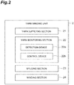
- each yarn winding unit 2 includes a yarn supplying section 21, a yarn monitoring section 22, a yarn joining section 23, and a winding section 24.
- each yarn winding unit 2 may include a tension applying device that applies tension and a tension sensor that measures the tension of yarn.
- each yarn winding unit 2 may include a tension sensor that measures the tension of yarn, a yarn storage device that stores therein the yarn, and a waxing device that applies wax to the yarn.
- the yarn supplying section 21 supplies yarn.
- the yarn supplying section 21 includes a bobbin supporting device that supports a bobbin.
- the yarn supplying section 21 includes a drafting device that drafts a fiber band and an air spinning device that generates yarn by twisting the drafted fiber band using swirling airflow.
- the yarn monitoring section 22 monitors the yarn between the yarn supplying section 21 and the winding section 24, and detects a yarn defect.
- the yarn monitoring section 22 includes a detection device 22a and a control device 22b.
- the detection device 22a is an optical sensor that emits light to yarn and detects time variation of thickness (diameter) of the yarn on the basis of the amount of received light, or a capacitive sensor that causes yarn to pass through an electric field and detects time variation of thickness (mass) of the yarn on the basis of variation of capacitance.
- the detection device 22a outputs waveform data indicating time variation of yarn thickness to the control device 22b.
- the control device 22b calculates yarn defect data indicating the length and the thickness of the yarn defect, and outputs the yarn defect data to the unit control device 3. If the unit control device 3 has determined based on the yarn defect data that the yarn defect needs to be removed, the yarn is cut by, for example, a cutter provided to the yarn winding unit 2. When the yarn winding machine 1 is the air spinning machine, the yarn may be cut by interrupting generation of the yarn by the air spinning device.
- the yarn monitoring section 22 can also detect a foreign matter contained in the yarn and yarn breakage, for example. Based on the yarn defect data, the control device 22b may determine whether the yarn defect needs to be removed, and a cutter provided to the yarn monitoring section 22 may cut the yarn.
- the yarn joining section 23 When the yarn has been cut in order to remove a yarn defect detected by the yarn monitoring section 22 or yarn breakage has been detected by the yarn monitoring section 22, the yarn joining section 23 performs splicing operation of splicing the yarn on the yarn supplying section 21 side and the yarn on the winding section 24 side.
- the yarn joining section 23 includes a first yarn catching-and-guiding device, a second yarn catching-and-guiding device, and a splicing part.
- the first yarn catching-and-guiding device catches the yarn on the yarn supplying section 21 side by suction, and guides the yarn to the splicing part.
- the second yarn catching-and-guiding device catches the yarn on the winding section 24 side by suction, and guides the yarn to the splicing part.
- the splicing part is, for example, a splicer using compressed air, a piecer using a seed yarn, or a knotter configured to mechanically splice yarns, and splices the yarns thus guided.
- the yarn joining section 23 may be configured as a splicing carrier that can travel with respect to the yarn winding units 2.
- the winding section 24 winds the yarn around a bobbin and forms a package.
- the winding section 24 includes a cradle arm, a winding drum, and a traverse device.
- the cradle arm rotatably supports the package.
- the winding drum comes into contact with a surface of the package supported by the cradle arm and rotates the package.
- the traverse device traverses the yarn by a predetermined width with respect to the rotating package.
- the winding drum may have a traverse groove, for example.
- the machine control device 4 includes a touch panel (display unit) 41, a processor 42, and a storage 43.
- the touch panel 41 displays various types of information for the operator, and receives various types of information input from the operator.
- the processor 42 acquires the yarn defect data output from the yarn monitoring section 22 of each yarn winding unit 2.
- the processor 42 causes the storage 43 to store therein, for each yarn winding unit 2, the acquired yarn defect data in a manner associated with information on whether the yarn defect has been removed or has not been removed.
- the processor 42 and the storage 43 physically include a central processing unit (CPU), a read only memory (ROM), and a random access memory (RAM).
- the processor 42 is a circuit configured to perform respective operations described later.
- FIG. 4 is a diagram illustrating one example of a screen of the touch panel 41.
- the two-dimensional field 51 is a coordinate system having coordinate axes respectively representing the length and the thickness of the yarn defect.
- the abscissa represents the length of the yarn defect
- the ordinate represents the thickness (ratio to a specified yarn thickness) of the yarn defect.
- the clearing limit 52 is a borderline whether the yarn defect needs to be removed, and includes a plurality of portions 52a.
- the clearing limit 52 is set for respective channels indicating types of yarn defects such as neps N1 and N2, slubs S1 and S2, a long yarn L, thin yarns T1 and T2.
- the respective portions 52a correspond to the neps N1 and N2, the slubs S1 and S2, the long yarn L, and the thin yarns T1 and T2, for example.
- the processor 42 causes the touch panel 41 to display a current set-value column 53 and a simulation set-value column 54.
- the current set-value column 53 current values of lengths and thicknesses of yarn defects that determine the clearing limit 52 are listed for the respective channels.
- the simulation set-value column 54 simulated values of lengths and thicknesses of yarn defects that determine the clearing limit 52 are listed for the respective channels.
- the respective portions 52a constituting the current clearing limit 52 are set so as to intersect the current values of lengths and thicknesses of the corresponding yarn defects.
- portions indicating the respective channels are configured as buttons 55.
- the processor 42 causes each unit control device 3 to control operation of the corresponding yarn winding units 2 such that yarn defects having values within an area on the specified yarn thickness side (the side of the abscissa in which the thickness of the yarn defect is 0%) with respect to the clearing limit 52 need not to be removed, and yarn defects having values within an area on the side opposite to the specified yarn thickness side (the side of the abscissa in which the thickness of the yarn defect is 0%) with respect to the clearing limit 52 need to be removed.
- the processor 42 determines the positions of yarn defects in the two-dimensional field 51, and causes the touch panel 41 to display the yarn defects as dots.
- the processor 42 causes yarn defects that have not been removed in the yarn to be displayed as hollow circular dots in the two-dimensional field 51, and causes yarn defects that have been removed from the yarn to be displayed as black square dots in the two-dimensional field 51.
- At least one portion 52a in the current clearing limit 52 can be changed.
- change of the clearing limit 52 with reference to one example thereof.
- the display mode e.g., at least one of line type, thickness, and color
- the display mode e.g., at least one of font and color
- the operator can select a portion 52a corresponding to a channel other than the slub S2 in the current clearing limit 52, and also can select a certain number of portions 52a therein at the same time.
- the clearing limit 52 functions as a first input section that receives selection of at least one portion 52a that has been touched.
- the processor 42 causes the touch panel 41 to display the portion 52a selected with the clearing limit 52 so that the portion 52a can be identified, and also causes the touch panel 41 to display a button 55 corresponding to the portion 52a so that the button 55 can be identified. Furthermore, when the clearing limit 52 has received selection of at least one portion 52a, the processor 42 causes the touch panel 41 to display the operation section 60 such that the operation section does not overlap this portion 52a.
- the display mode of the touched button 55 is changed, the display mode of a portion corresponding to the slub S2 in the current clearing limit 52 is changed, and the operation section 60 is displayed.
- the operator can select a button 55 corresponding to a channel other than the slub S2 among the buttons 55 in the set-value column 53, and also can select a certain number of buttons 55 therein at the same time.
- buttons 55 (the buttons 55 displayed separately from the clearing limit 52 by the touch panel 41) each corresponding to the portions 52a constituting the clearing limit 52 function as the first input section that receives selection of a portion 52a corresponding to at least one button 55 that has been touched.
- the processor 42 causes the touch panel 41 to display the portion 52a selected with the button 55 so that the portion 52a can be identified, and also causes the touch panel 41 to display the button 55 corresponding to the portion 52a so that the button 55 can be identified. Furthermore, when the button 55 has received selection of at least one portion 52a, the processor 42 causes the touch panel 41 to display the operation section 60 such that the operation section does not overlap this portion 52a.
- the operation section 60 functions as a second input section that indicates a plurality of moving directions for the clearing limit 52 and receives selection of a moving direction thereamong.
- the processor 42 changes the clearing limit 52 such that a portion 52a selected with the clearing limit 52 or a button 55 moves in a moving direction selected with the operation section 60 by a predetermined amount, and causes the touch panel 41 to display the clearing limit 52 thus changed.
- the operation section 60 has moving-direction instruction buttons 61, a moving-amount change button 62, a display cancel button 63, and a display-position move button 64.
- the moving-direction instruction buttons 61 indicate a plurality of moving directions at intervals of a predetermined angle and receive selection of a moving direction thereamong.
- the moving-direction instruction buttons 61 are arranged around the moving-amount change button 62 at intervals of 45 degrees, and indicate moving directions of upper, upper-right, right, lower-right, lower, lower-left, left, and upper-left clockwise in this order.
- a portion 52a corresponding to the selected slub S2 moves rightward by the predetermined amount.
- the processor 42 causes the touch panel 41 to display the clearing limit 52 changed and also the clearing limit 52 before being changed so that these clearing limits can be identified from one another by changing display modes.
- the processor 42 changes the simulated values of length and thickness of the yarn defect that determine the portion 52a corresponding to the slub S2 in the clearing limit 52 changed, and causes the touch panel 41 to display the resulting simulated values.
- the portion 52a corresponding to the slub S2 moves rightward by the predetermined amount, and thus the value and the color, for example, of only the simulated value of length of the yarn defect are changed.
- the portion 52a corresponding to the selected slub S2 moves upward by the predetermined amount.
- the processor 42 causes the touch panel 41 to display the clearing limit 52 changed and also the clearing limit 52 before being changed so that these clearing limits can be identified from one another by changing display modes.
- the processor 42 changes the simulated values of length and thickness of the yarn defect that determine the portion 52a corresponding to the slub S2 in the clearing limit 52 changed, and causes the touch panel 41 to display the resulting simulated values.
- the portion 52a corresponding to the slub S2 moves upward by the predetermined amount, and thus the value and the color, for example, of only the simulated value of thickness of the yarn defect are changed.
- the portion 52a corresponding to the selected slub S2 moves upper-rightward by the predetermined amount.
- the processor 42 causes the touch panel 41 to display the clearing limit 52 changed and also the clearing limit 52 before being changed so that these clearing limits can be identified from one another by changing display modes.
- the processor 42 changes the simulated values of length and thickness of the yarn defect that determine the portion 52a corresponding to the slub S2 in the clearing limit 52 changed, and causes the touch panel 41 to display the resulting simulated values.
- the portion 52a corresponding to the slub S2 moves upper-rightward by the predetermined amount, and thus the values and the colors, for example, of the simulated values of length and thickness of the yarn defect are changed.
- the moving-amount change button 62 receives change of the amount (predetermined amount) by which the selected portion 52a moves in response to touching once the moving-direction instruction button 61. For example, each time the moving-amount change button 62 is touched, the processor 42 changes the moving amount to ⁇ 1 (moving amount that is one time as long as a reference value), to ⁇ 10 (moving amount that is 10 times as long as the reference value), and to ⁇ 100 (moving amount that is 100 times as long as the reference value).
- the reference value for the moving amount can be set for each channel.
- the display cancel button 63 receives cancellation of display of the operation section 60 on the touch panel 41. Specifically, when the clearing limit 52 or a button 55 has received selection of at least one portion 52a, the processor 42 causes the touch panel 41 to display the operation section 60, and when the display cancel button 63 has been touched, the processor cancels the display of the operation section 60 to release the selection of the portion 52a.
- the display-position move button 64 receives movement of the display position of the operation section 60 on the touch panel 41.
- the operator can move the operation section 60 to any position in the screen by touching the display-position move button 64.
- the operation section 60 is displayed in an upper-right area of the two-dimensional field 51 in a manner in which part thereof lies out of the area.
- the operation section 60 is displayed in an upper-right area of the two-dimensional field 51 in a manner in which part thereof lies out of the area as depicted in FIG. 10 . If portions 52a corresponding to the long yarn L and the thin yarn T2 in the clearing limit 52 are displayed in an enlarged manner, when the portion 52a corresponding to the long yarn L has been selected, the operation section 60 is displayed in an lower-right area of the two-dimensional field 51 in a manner in which part thereof lies out of the area as depicted in FIG. 11 .
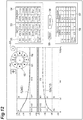
- the operation section 60 is displayed in an upper-right area of the two-dimensional field 51 in a manner in which part thereof lies out of the area as depicted in FIG. 12 .
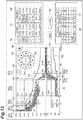
- a clearing simulation can be performed. The following describes the clearing simulation with reference to FIG. 13 .
- the processor 42 calculates a first yarn processing result, and causes the touch panel 41 to display the first yarn processing result.
- the processor 42 causes the first yarn processing result to be displayed as a yarn processing result based on the clearing limit 52 before being changed in a current result column 56.
- the processor 42 calculates a second yarn processing result, and causes the touch panel 41 to display the second yarn processing result.
- the processor 42 causes the second yarn processing result to be displayed as a yarn processing result based on the clearing limit 52 changed in a simulation result column 57.
- the number (n) of removed yarn defects and the converted number (/100 km) of removed yarn defects per unit length are displayed for the respective channels.
- the number (n) of removed yarn defects in the current result column 56 is the measured number of yarn defects that have been removed, and corresponds to the number of dots of yarn defects having values within an area on the side opposite to the specified yarn thickness side (the side of the abscissa in which the thickness of the yarn defect is 0%) with respect to the clearing limit 52 before being changed.
- the number (n) of removed yarn defects may be converted into a number per unit time (e.g., 1 hour), and this converted number of removed yarn defects may be displayed in the current result column 56.
- the first yarn processing result either one of the number of removed yarn defects and the converted number of removed yarn defects per unit length may be displayed.
- the number (n) of removed yarn defects and the converted number (/100 km) of removed yarn defects per unit length are displayed for the respective channels.
- the number (n) of removed yarn defects in the simulation result column 57 is a predicted number based on the measured number of yarn defects, and corresponds to the number of dots of yarn defects having values within an area on the side opposite to the specified yarn thickness side (the side of the abscissa in which the thickness of the yarn defect is 0%) with respect to the clearing limit 52 changed.
- the number (n) of removed yarn defects may be converted into a number per unit time (e.g., 1 hour), and this converted number of removed yarn defects may be displayed in the simulation result column 57.
- this converted number of removed yarn defects may be displayed in the simulation result column 57.
- the simulation result column 57 as the second yarn processing result, either one of the number of removed yarn defects and the converted number of removed yarn defects per unit length may be displayed.
- the amount of increase or decrease of the second yarn processing result from the first yarn processing result may be displayed.
- portions 52a corresponding to the nep N2 and the slub S1 in the clearing limit 52 have been selected with the clearing limit 52 or buttons 55, and these portions 52a have been moved downward by the predetermined amount with the operation section 60 (see the current set-value column 53 and the simulation set-value column 54).
- the numbers of removed yarn defects for the nep N and the slub S have increased (see the current result column 56 and the simulation result column 57).
- This clearing simulation is started when the operator touches a simulation button 58, and is ended when the operator touches again the simulation button 58.
- a reset button 59 is a button configured to receive cancellation (reset) of setting (during simulation) of changing the clearing limit 52.
- the simulation button 58 and the reset button 59 do not have to be provided.
- the second yarn processing result may be automatically (without waiting for another instruction by the operator) displayed.
- the clearing limit 52 changed through simulation may be set as a new clearing limit 52.
- the number of removed yarn defects when what is called "class cut” is performed is displayed.
- the class cut is to remove yarn defects having values within an area that is selected from among a plurality of areas (classes) constituting the two-dimensional field 51.
- the sum of the numbers (n) of removed yarn defects and the sum of the numbers (/100 km) of removed yarn defects per unit length are displayed.
- the clearing limit 52 may be configured to be changed in response to input of the number of removed yarn defects per unit length (e.g., 100 kilometers). In this case, the clearing limit 52 may be configured to be finely adjusted by operating the operation section 60 after a temporary clearing limit 52 depending on the number of removed yarn defects per unit length is displayed.
- the processor 42 sets the clearing limit 52 before being changed or the clearing limit 52 changed as a new clearing limit 52.
- This setting of the clearing limit 52 is performed when the operator who has viewed the clearing simulation result touches a button (not depicted) for selecting the clearing limit 52 before being changed or the clearing limit 52 changed.
- Changing of the clearing limit 52 and displaying of the clearing limit 52 changed are functions of a first mode that the processor 42 has.
- the processor 42 has a second mode in addition to the first mode.
- the second mode is a mode of changing the clearing limit 52 so as to remove yarn defects corresponding to an area touched among the areas constituting the two-dimensional field 51, and causing the touch panel 41 to display the clearing limit 52 changed.
- the processor 42 changes the part D1a of the clearing limit 52 so as to remove yarn defects having values within the class D1.
- the second mode may be a mode of changing the clearing limit 52 so as not to remove yarn defects corresponding to an area touched among the areas constituting the two-dimensional field 51, and causing the touch panel 41 to display the clearing limit 52 changed.
- the processor 42 changes the part D0a of the clearing limit 52 so as not to remove yarn defects having values within the class D0.
- At least one portion 52a among the portions 52a constituting the clearing limit 52 can be selected, and the selected portion 52a can be moved.
- the operation section 60 that moves the selected portion 52a indicates the moving directions for the clearing limit 52. This allows the operator to intuitively move the selected portion 52a in a desired moving direction with the operation section 60.
- at least one portion 52a among the portions 52a constituting the clearing limit 52 can be easily and appropriately changed. In other words, with the machine control device 4, at least one portion of the clearing limit 52 can be easily and appropriately changed.
- the clearing limit 52 displayed by the touch panel 41 receives selection of a portion 52a that has been touched among the portions 52a. This allows the operator to easily select a desired portion 52a in the clearing limit 52.
- the processor 42 causes the touch panel 41 to display the selected portion 52a such that the portion 52a becomes identifiable. This allows the operator to grasp whether the desired portion 52a in the clearing limit 52 has been selected correctly.
- the clearing limit 52 includes the portions 52a, and receives selection of at least one portion 52a. This allows the operator to easily select a desired portion from among the portions 52a that are divided in advance.
- each of the portions 52a is set depending on the type of the yarn defect. This allows one portion of the clearing limit 52 to be easily selected and changed depending on the type of the yarn defect.
- buttons 55 that are displayed separately from the clearing limit 52 by the touch panel 41 receive selection of a portion 52a corresponding to a button 55 that has been touched among the buttons 55. This allows the operator to easily select a desired portion 52a of the clearing limit 52 even among portions 52a of the clearing limit 52 that are finely displayed.
- the processor 42 causes the touch panel 41 to display the selected button 55 such that the button 55 becomes identifiable. This allows the operator to grasp whether the desired portion 52a in the clearing limit 52 has been selected correctly.
- the touch panel 41 displays the operation section 60. This enables the operation section 60 to be provided to the operator at appropriate timing, thereby eliminating the need to provide an additional operation section 60.
- the processor 42 causes the touch panel 41 to display the operation section 60 when selection of a portion 52a has been received. This can prevent the operation section 60 from occupying a display area of the touch panel 41 during a period of time other than when the clearing limit 52 is changed.
- the processor 42 causes the touch panel 41 to display the operation section 60 such that the operation section does not overlap the selected portion 52a. This allows the operator to operate the operation section 60 while visually checking the selected portion 52a.
- the operation section 60 includes the moving-direction instruction buttons 61 that indicates a plurality of moving directions at intervals of a predetermined angle and receives selection of a moving direction thereamong. This allows the operator to intuitively grasp the moving directions and operate the operation section 60.
- the operation section 60 includes the moving-amount change button 62 that receives change of a predetermined amount. This allows the operator to move the selected portion 52a by a large amount or to move the selected portion by a small amount.
- the operation section 60 includes the display cancel button 63 that receives cancellation of display of the operation section 60 on the touch panel 41. This allows the operator to easily change the state in which the clearing limit 52 has been selected back to the state in which the clearing limit has not been selected.
- the operation section 60 includes the display-position move button 64 that receives movement of the display position of the operation section 60 on the touch panel 41. This allows the operator to move the operation section 60 to any position in the display area of the touch panel 41 to check an area hidden by the operation section 60 in the display area.
- the processor 42 has: the first mode of changing the clearing limit 52 as described above and causing the touch panel 41 to display the clearing limit 52 changed; and the second mode of changing the clearing limit 52 so as to remove or not to remove the yarn defect corresponding to an area touched among a plurality of areas constituting the two-dimensional field 51 and causing the touch panel 41 to display the clearing limit 52 changed.
- This allows the operator to change the clearing limit 52 with the operation section 60, and also allows the operator to change the clearing limit 52 on the basis of area designation in the two-dimensional field 51.
- the processor 42 may cause the touch panel 41 to display the clearing limit 52 changed and also the clearing limit 52 before being changed. This allows the operator to compare the clearing limit 52 changed with the clearing limit 52 before being changed.
- the processor 42 acquires yarn defect data indicating the length and the thickness of the yarn defect, calculates a first yarn processing result based on the yarn defect data and the clearing limit 52 before being changed, calculates a second yarn processing result based on the yarn defect data and the clearing limit 52 changed, and causes the touch panel 41 to display the first yarn processing result and the second yarn processing result. This allows the operator to compare the first yarn processing result with the second yarn processing result to evaluate each of the clearing limit 52 before being changed and the clearing limit 52 changed.
- the processor 42 sets the clearing limit 52 before being changed or the clearing limit 52 changed as a new clearing limit 52. This allows the operator to set the clearing limit 52 before being changed or the clearing limit 52 changed as a new clearing limit 52.
- the yarn winding machine 1 includes: the yarn supplying section 21 that supplies yarn; the winding section 24 that winds the yarn and forms a package; the yarn monitoring section 22 that monitors the yarn between the yarn supplying section 21 and the winding section 24, and detects a yarn defect; the yarn joining section 23 that, when the yarn has been cut to remove the yarn defect detected by the yarn monitoring section 22, performs splicing operation of splicing the yarn on the yarn supplying section 21 side and the yarn on the winding section 24 side; and the machine control device 4.
- the yarn winding machine 1 includes the machine control device 4 described above, and thus can remove a yarn defect appropriately.
- the clearing-limit setting device and the yarn winding machine of the present disclosure are not limited to the embodiment.
- the clearing limit 52 and the buttons 55 displayed by the touch panel 41 function as the first input section that receives selection of at least one portion 52a among the portions 52a constituting the clearing limit 52.
- a first input section including a mechanical button may be provided separately from the touch panel 41.
- the operation section 60 displayed by the touch panel 41 functions as the second input section that indicates a plurality of moving directions for the clearing limit 52 and receives selection of a moving direction thereamong.
- a second input section including a mechanical button and a lever may be provided separately from the touch panel 41.
- the portions 52a constituting the clearing limit 52 correspond to the respective channels.
- the portions 52a may correspond to units other than the channels.
- the machine control device 4 of the yarn winding machine 1 functions as the clearing-limit setting device.
- a management device located separately from the yarn winding machine 1 may function as the clearing-limit setting device.
- a clearing setting device dedicated to the yarn monitoring section 22 may be provided.
- the processor 42 may also acquire waveform data output from the detection device 22a of the yarn monitoring section 22, in addition to acquiring yarn defect data from the control device 22b of the yarn monitoring section 22.
- the processor 42 may acquire only waveform data output from the detection device 22a of the yarn monitoring section 22, without acquiring yarn defect data from the control device 22b of the yarn monitoring section 22.
- the processor 42 can calculate yarn defect data based on the acquired waveform data.
- the amount of production may be displayed together with the number of removed yarn defects.
- the clearing limit 52 corresponding to this number or amount may be displayed, and then the clearing limit 52 may be able to be finely adjusted by operating the operation section 60.
- the clearing limit 52 may be touched, or the corresponding button 55maybe touched. All portions of the clearing limit 52 maybe selected.
- the processor 42 may have: the first mode of changing the clearing limit 52 as described above and causing the touch panel 41 to display the clearing limit 52 changed; and a second mode of causing the touch panel 41 to display an area touched among a plurality of areas constituting the two-dimensional field 51 such that whether to remove or not to remove a yarn defect corresponding to the touched area becomes distinguishable. This allows the operator to change the clearing limit 52 with the operation section 60, and also allows the operator to change a clearing area on the basis of area designation in the two-dimensional field 51.
- the clearing-limit setting device does not have to have the above-described function of performing the clearing simulation.
- the clearing-limit setting device may have the above-described function of performing the clearing simulation as an additional function.
- at least one portion 52a among the portions 52a constituting the clearing limit 52 can be easily and appropriately changed, and thus the clearing-limit setting device and the yarn winding machine of the present disclosure are significantly effective.
- the clearing limit 52 is divided (segmented) into the portions 52a in advance, and at least one portion 52a among the portions 52a is selectable by the operator.
- at least one portion of clearing limit 52 may be selectable by the operator without dividing the clearing limit 52 in advance.
- at least one portion of the clearing limit 52 may be selectable when the operator inputs with an input section a numerical range (e.g., at least one of the upper limit and the lower limit of at least one of thickness and length) of the clearing limit 52.
- at least one portion of the clearing limit 52 may be selectable when the operator touches part of the clearing limit 52 in a tracing manner on the touch panel 41.
- the at least one portion of the clearing limit 52 selection of which the first input section receives may be one continuous portion, or may be two or more portions located separately from each other.
- the at least one portion may be one portion, may be two or more portions continuously located, or may be two or more portions located separately from each other.
Landscapes
- Engineering & Computer Science (AREA)
- Textile Engineering (AREA)
- Mechanical Engineering (AREA)
- Quality & Reliability (AREA)
- Chemical & Material Sciences (AREA)
- Materials Engineering (AREA)
- Treatment Of Fiber Materials (AREA)
- Filamentary Materials, Packages, And Safety Devices Therefor (AREA)
- Spinning Or Twisting Of Yarns (AREA)
Abstract
Description
- The present disclosure relates to a clearing-limit setting device and a yarn winding machine.
- For example, a machine control device of an air spinning machine may have a function of displaying a clearing limit that is a borderline whether a yarn defect needs to be removed in a two-dimensional field having coordinate axes respectively representing the length and the thickness of a yarn defect (see Japanese Unexamined Patent Publication No.
2007-211363 - When part of a clearing limit displayed as described above is changed, the length and the thickness of the yarn defect that determine this part are input as numerical values. However, there is a situation in which the changed part of the clearing limit does not have an expected shape and accordingly the numerical values need to be input again and again.
- In view of this, the present disclosure aims to provide a clearing-limit setting device and a yarn winding machine that can easily and appropriately change at least one portion of a clearing limit.
- A clearing-limit setting device according to one aspect of the present disclosure includes: a display unit that displays, in a two-dimensional field having coordinate axes respectively representing length and thickness of a yarn defect, a clearing limit that is a borderline whether the yarn defect needs to be removed; a first input section that receives selection of at least one portion of the clearing limit; a second input section that indicates a plurality of moving directions for the clearing limit and receives selection of a moving direction thereamong; and a processor that changes the clearing limit such that the at least one portion selected with the first input section moves in the moving direction selected with the second input section by a predetermined amount, and causes the display unit to display the clearing limit changed.
- With this clearing-limit setting device, at least one portion of the clearing limit can be selected, and the at least one portion selected can be moved. The second input section that moves the at least one portion selected indicates the moving directions for the clearing limit. This allows an operator to intuitively move the at least one portion selected in a desired moving direction with the second input section. Thus, with this clearing-limit setting device, at least one portion of the clearing limit can be easily and appropriately changed.
- In the clearing-limit setting device according to one aspect of the present disclosure, the first input section may include the clearing limit displayed by the display unit and receive selection of at least one portion that has been touched in the clearing limit. This allows the operator to easily select a desired portion in the clearing limit.
- In the clearing-limit setting device according to one aspect of the present disclosure, the processor may cause the display unit to display the at least one portion selected with the first input section such that the at least one portion becomes identifiable. This allows the operator to grasp whether the desired portion in the clearing limit has been selected correctly.
- In the clearing-limit setting device according to one aspect of the present disclosure, the clearing limit may include a plurality of portions, and the first input sectionmay receive selection of at least one portion among the portions. This allows the operator to easily select a desired portion from among a plurality of portions that are divided in advance.
- In the clearing-limit setting device according to one aspect of the present disclosure, each of the portions may be set depending on the type of the yarn defect. This allows one portion of the clearing limit to be easily selected and changed depending on the type of the yarn defect.
- In the clearing-limit setting device according to one aspect of the present disclosure, the display unit may display a plurality of buttons respectively corresponding to the portions separately from the clearing limit, and the first input section may include the buttons displayed by the display unit and receive selection of a portion corresponding to a button that has been touched among the buttons. This allows the operator to easily select a desired portion of the clearing limit even among portions of the clearing limit that are finely displayed.
- In the clearing-limit setting device according to one aspect of the present disclosure, the processor may cause the display unit to display the button selected with the first input section such that the button becomes identifiable. This allows the operator to grasp whether the desired portion in the clearing limit has been selected correctly.
- In the clearing-limit setting device according to one aspect of the present disclosure, the second input section may be an operation section displayed by the display unit. This enables the operation section to be provided to the operator at appropriate timing, thereby eliminating the need to provide an additional operation section.
- In the clearing-limit setting device according to one aspect of the present disclosure, the processor may cause the display unit to display the operation section when the first input section has received selection of the at least one portion. This can prevent the operation section from occupying a display area of the display unit during a period of time other than when the clearing limit is changed.
- In the clearing-limit setting device according to one aspect of the present disclosure, the processor may cause the display unit to display the operation section such that the operation section does not overlap the at least one portion selected with the first input section. This allows the operator to operate the operation section while visually checking the selected portion.
- In the clearing-limit setting device according to one aspect of the present disclosure, the operation section may include a moving-direction instruction button that indicates a plurality of moving directions at intervals of a predetermined angle and receives selection of a moving direction thereamong. This allows the operator to intuitively grasp the moving directions and operate the operation section.
- In the clearing-limit setting device according to one aspect of the present disclosure, the operation section may further include a moving-amount change button that receives change of a predetermined amount. This allows the operator to move the selected portion by a large amount or to move the selected portion by a small amount.
- In the clearing-limit setting device according to one aspect of the present disclosure, the operation section may further include a display cancel button that receives cancellation of display of the operation section on the display unit. This allows the operator to easily change the state in which the clearing limit has been selected back to the state in which the clearing limit has not been selected.
- In the clearing-limit setting device according to one aspect of the present disclosure, the operation section may further include a display-position move button that receives movement of a display position of the operation section on the display unit. This allows the operator to move the operation section to any position in the display area of the display unit to check an area hidden by the operation section in the display area.
- In the clearing-limit setting device according to one aspect of the present disclosure, the processor may have: a first mode of changing the clearing limit with the first input section and the second input section and causing the display unit to display the clearing limit changed; and a second mode of changing the clearing limit so as to remove or not to remove the yarn defect corresponding to an area touched among a plurality of areas constituting the two-dimensional field and causing the display unit to display the clearing limit changed. This allows the operator to change the clearing limit with the operation section, and also allows the operator to change the clearing limit on the basis of area designation in the two-dimensional field.
- In the clearing-limit setting device according to one aspect of the present disclosure, the processor may have: a first mode of changing the clearing limit with the first input section and the second input section and causing the display unit to display the clearing limit changed; and a second mode of causing the display unit to display an area touched among a plurality of areas constituting the two-dimensional field such that whether to remove or not to remove the yarn defect corresponding to the area touched becomes distinguishable. This allows the operator to change the clearing limit with the operation section, and also allows the operator to change a clearing area on the basis of area designation in the two-dimensional field.
- In the clearing-limit setting device according to one aspect of the present disclosure, the processor may cause the display unit to display the clearing limit changed and also the clearing limit before being changed. This allows the operator to compare the clearing limit changed with the clearing limit before being changed.
- In the clearing-limit setting device according to one aspect of the present disclosure, the processor may acquire yarn defect data indicating the length and the thickness of the yarn defect, calculate a first yarn processing result based on the yarn defect data and the clearing limit before being changed, calculate a second yarn processing result based on the yarn defect data and the clearing limit changed, and cause the display unit to display the first yarn processing result and the second yarn processing result. This allows the operator to compare the first yarn processing result with the second yarn processing result to evaluate each of the clearing limit before being changed and the clearing limit changed.
- In the clearing-limit setting device according to one aspect of the present disclosure, the processor may set the clearing limit before being changed or the clearing limit changed as a new clearing limit. This allows the operator to set the clearing limit before being changed or the clearing limit changed as a new clearing limit.
- A yarn winding machine according to one aspect of the present disclosure includes: a yarn supplying section that supplies yarn; a winding section that winds the yarn and forms a package; a yarn monitoring section that monitors the yarn between the yarn supplying section and the winding section, and detects a yarn defect; a yarn joining section that, when the yarn has been cut to remove the yarn defect detected by the yarn monitoring section, performs splicing operation of splicing the yarn on the yarn supplying section side and the yarn on the winding section side; and the clearing-limit setting device described above.
- This yarn winding machine includes the clearing-limit setting device described above, and thus can remove a yarn defect appropriately.
- According to the present disclosure, it is possible to provide the clearing-limit setting device and the yarn winding machine that can easily and appropriately change at least one portion of the clearing limit.
-
-
FIG. 1 is a block diagram illustrating a configuration of a yarn winding machine according to one embodiment; -
FIG. 2 is a block diagram illustrating a configuration of a yarn winding unit inFIG. 1 ; -
FIG. 3 is a block diagram illustrating a configuration of a machine control device inFIG. 1 ; -
FIG. 4 is a diagram illustrating one example of a screen of a touch panel inFIG. 1 ; -
FIG. 5 is a diagram illustrating one example of the screen of the touch panel inFIG. 1 ; -
FIG. 6 is a diagram illustrating one example of the screen of the touch panel inFIG. 1 ; -
FIG. 7 is a diagram illustrating one example of the screen of the touch panel inFIG. 1 ; -
FIG. 8 is a diagram illustrating one example of the screen of the touch panel inFIG. 1 ; -
FIG. 9 is a diagram illustrating one example of the screen of the touch panel inFIG. 1 ; -
FIG. 10 is a diagram illustrating one example of the screen of the touch panel inFIG. 1 ; -
FIG. 11 is a diagram illustrating one example of the screen of the touch panel inFIG. 1 ; -
FIG. 12 is a diagram illustrating one example of the screen of the touch panel inFIG. 1 ; -
FIG. 13 is a diagram illustrating one example of the screen of the touch panel inFIG. 1 ; and -
FIG. 14 is a diagram illustrating one example of the screen of the touch panel inFIG. 1 . - An embodiment of the present disclosure will now be described in detail with reference to the drawings. In the drawings, like or equivalent elements are designated by like numerals, and duplicate description is omitted.
- As depicted in
FIG. 1 , ayarn winding machine 1 includes a plurality ofyarn winding units 2, a plurality ofunit control devices 3, and a machine control device (clearing-limit setting device) 4. Theyarn winding machine 1 is an automatic winder, an air spinning machine, an open-end spinning machine, or a ring spinning machine, for example. Eachyarn winding unit 2 winds yarn and forms a package. Eachunit control device 3 is provided for every certain number ofyarn winding units 2, and controls operation of theyarn winding units 2 under management thereof. Themachine control device 4 communicates with eachunit control device 3 and controls operation of theyarn winding machine 1. Eachunit control device 3 may be provided for everyyarn winding unit 2. - As depicted in
FIG. 2 , eachyarn winding unit 2 includes ayarn supplying section 21, ayarn monitoring section 22, ayarn joining section 23, and a windingsection 24. When theyarn winding machine 1 is an automatic winder, eachyarn winding unit 2 may include a tension applying device that applies tension and a tension sensor that measures the tension of yarn. When theyarn winding machine 1 is an air spinning machine, eachyarn winding unit 2 may include a tension sensor that measures the tension of yarn, a yarn storage device that stores therein the yarn, and a waxing device that applies wax to the yarn. - The
yarn supplying section 21 supplies yarn. When theyarn winding machine 1 is the automatic winder, theyarn supplying section 21 includes a bobbin supporting device that supports a bobbin. When theyarn winding machine 1 is the air spinning machine, theyarn supplying section 21 includes a drafting device that drafts a fiber band and an air spinning device that generates yarn by twisting the drafted fiber band using swirling airflow. - The
yarn monitoring section 22 monitors the yarn between theyarn supplying section 21 and the windingsection 24, and detects a yarn defect. Theyarn monitoring section 22 includes adetection device 22a and acontrol device 22b. Thedetection device 22a is an optical sensor that emits light to yarn and detects time variation of thickness (diameter) of the yarn on the basis of the amount of received light, or a capacitive sensor that causes yarn to pass through an electric field and detects time variation of thickness (mass) of the yarn on the basis of variation of capacitance. Thedetection device 22a outputs waveform data indicating time variation of yarn thickness to thecontrol device 22b. Based on the waveform data, thecontrol device 22b calculates yarn defect data indicating the length and the thickness of the yarn defect, and outputs the yarn defect data to theunit control device 3. If theunit control device 3 has determined based on the yarn defect data that the yarn defect needs to be removed, the yarn is cut by, for example, a cutter provided to theyarn winding unit 2. When theyarn winding machine 1 is the air spinning machine, the yarn may be cut by interrupting generation of the yarn by the air spinning device. Theyarn monitoring section 22 can also detect a foreign matter contained in the yarn and yarn breakage, for example. Based on the yarn defect data, thecontrol device 22b may determine whether the yarn defect needs to be removed, and a cutter provided to theyarn monitoring section 22 may cut the yarn. - When the yarn has been cut in order to remove a yarn defect detected by the
yarn monitoring section 22 or yarn breakage has been detected by theyarn monitoring section 22, theyarn joining section 23 performs splicing operation of splicing the yarn on theyarn supplying section 21 side and the yarn on the windingsection 24 side. Theyarn joining section 23 includes a first yarn catching-and-guiding device, a second yarn catching-and-guiding device, and a splicing part. The first yarn catching-and-guiding device catches the yarn on theyarn supplying section 21 side by suction, and guides the yarn to the splicing part. The second yarn catching-and-guiding device catches the yarn on the windingsection 24 side by suction, and guides the yarn to the splicing part. The splicing part is, for example, a splicer using compressed air, a piecer using a seed yarn, or a knotter configured to mechanically splice yarns, and splices the yarns thus guided. When theyarn winding machine 1 is a spinning machine, for example, theyarn joining section 23 may be configured as a splicing carrier that can travel with respect to theyarn winding units 2. - The winding
section 24 winds the yarn around a bobbin and forms a package. The windingsection 24 includes a cradle arm, a winding drum, and a traverse device. The cradle arm rotatably supports the package. The winding drum comes into contact with a surface of the package supported by the cradle arm and rotates the package. The traverse device traverses the yarn by a predetermined width with respect to the rotating package. When a motor directly drives and rotates the package, the winding drum may have a traverse groove, for example. - As depicted in
FIG. 3 , themachine control device 4 includes a touch panel (display unit) 41, aprocessor 42, and astorage 43. Thetouch panel 41 displays various types of information for the operator, and receives various types of information input from the operator. Theprocessor 42 acquires the yarn defect data output from theyarn monitoring section 22 of eachyarn winding unit 2. Theprocessor 42 causes thestorage 43 to store therein, for eachyarn winding unit 2, the acquired yarn defect data in a manner associated with information on whether the yarn defect has been removed or has not been removed. Theprocessor 42 and thestorage 43 physically include a central processing unit (CPU), a read only memory (ROM), and a random access memory (RAM). Theprocessor 42 is a circuit configured to perform respective operations described later. - The
processor 42 generates a two-dimensional field, and causes thetouch panel 41 to display the two-dimensional field together with a clearing limit.FIG. 4 is a diagram illustrating one example of a screen of thetouch panel 41. As depicted inFIG. 4 , the two-dimensional field 51 is a coordinate system having coordinate axes respectively representing the length and the thickness of the yarn defect. Herein, the abscissa represents the length of the yarn defect, and the ordinate represents the thickness (ratio to a specified yarn thickness) of the yarn defect. Theclearing limit 52 is a borderline whether the yarn defect needs to be removed, and includes a plurality ofportions 52a. Herein, theclearing limit 52 is set for respective channels indicating types of yarn defects such as neps N1 and N2, slubs S1 and S2, a long yarn L, thin yarns T1 and T2. In other words, therespective portions 52a correspond to the neps N1 and N2, the slubs S1 and S2, the long yarn L, and the thin yarns T1 and T2, for example. - The
processor 42 causes thetouch panel 41 to display a current set-value column 53 and a simulation set-value column 54. In the current set-value column 53, current values of lengths and thicknesses of yarn defects that determine theclearing limit 52 are listed for the respective channels. In the simulation set-value column 54, simulated values of lengths and thicknesses of yarn defects that determine theclearing limit 52 are listed for the respective channels. Therespective portions 52a constituting thecurrent clearing limit 52 are set so as to intersect the current values of lengths and thicknesses of the corresponding yarn defects. When at least oneportion 52a in thecurrent clearing limit 52 is changed (details will be described later), simulated values of the length and the thickness of the yarn defect are changed so as to correspond to the changedportion 52a. In the current set-value column 53 and the simulation set-value column 54, portions indicating the respective channels are configured asbuttons 55. - The
processor 42 causes eachunit control device 3 to control operation of the correspondingyarn winding units 2 such that yarn defects having values within an area on the specified yarn thickness side (the side of the abscissa in which the thickness of the yarn defect is 0%) with respect to theclearing limit 52 need not to be removed, and yarn defects having values within an area on the side opposite to the specified yarn thickness side (the side of the abscissa in which the thickness of the yarn defect is 0%) with respect to theclearing limit 52 need to be removed. Based on the yarn defect data stored in thestorage 43, theprocessor 42 determines the positions of yarn defects in the two-dimensional field 51, and causes thetouch panel 41 to display the yarn defects as dots. Herein, theprocessor 42 causes yarn defects that have not been removed in the yarn to be displayed as hollow circular dots in the two-dimensional field 51, and causes yarn defects that have been removed from the yarn to be displayed as black square dots in the two-dimensional field 51. - In the
machine control device 4, at least oneportion 52a in thecurrent clearing limit 52 can be changed. The following describes change of theclearing limit 52 with reference to one example thereof. - For example, as depicted in
FIG. 5 , when the operator has touched (has pressed, has come into physical contact with, etc.) aportion 52a corresponding to the slub S2 in thecurrent clearing limit 52, the display mode (e.g., at least one of line type, thickness, and color) of the touchedportion 52a is changed, the display mode (e.g., at least one of font and color) of abutton 55 corresponding to the slub S2 among thebuttons 55 in the set-value column 53 is changed, and anoperation section 60 is displayed. At this time, the operator can select aportion 52a corresponding to a channel other than the slub S2 in thecurrent clearing limit 52, and also can select a certain number ofportions 52a therein at the same time. - In this manner, the
clearing limit 52 functions as a first input section that receives selection of at least oneportion 52a that has been touched. Theprocessor 42 causes thetouch panel 41 to display theportion 52a selected with theclearing limit 52 so that theportion 52a can be identified, and also causes thetouch panel 41 to display abutton 55 corresponding to theportion 52a so that thebutton 55 can be identified. Furthermore, when theclearing limit 52 has received selection of at least oneportion 52a, theprocessor 42 causes thetouch panel 41 to display theoperation section 60 such that the operation section does not overlap thisportion 52a. - Similarly also when the operator has touched the
button 55 corresponding to the slub S2 among thebuttons 55 in the set-value column 53, the display mode of the touchedbutton 55 is changed, the display mode of a portion corresponding to the slub S2 in thecurrent clearing limit 52 is changed, and theoperation section 60 is displayed. At this time, the operator can select abutton 55 corresponding to a channel other than the slub S2 among thebuttons 55 in the set-value column 53, and also can select a certain number ofbuttons 55 therein at the same time. - In this manner, the buttons 55 (the
buttons 55 displayed separately from theclearing limit 52 by the touch panel 41) each corresponding to theportions 52a constituting theclearing limit 52 function as the first input section that receives selection of aportion 52a corresponding to at least onebutton 55 that has been touched. Theprocessor 42 causes thetouch panel 41 to display theportion 52a selected with thebutton 55 so that theportion 52a can be identified, and also causes thetouch panel 41 to display thebutton 55 corresponding to theportion 52a so that thebutton 55 can be identified. Furthermore, when thebutton 55 has received selection of at least oneportion 52a, theprocessor 42 causes thetouch panel 41 to display theoperation section 60 such that the operation section does not overlap thisportion 52a. - The
operation section 60 functions as a second input section that indicates a plurality of moving directions for theclearing limit 52 and receives selection of a moving direction thereamong. Theprocessor 42 changes theclearing limit 52 such that aportion 52a selected with theclearing limit 52 or abutton 55 moves in a moving direction selected with theoperation section 60 by a predetermined amount, and causes thetouch panel 41 to display theclearing limit 52 thus changed. Specifically, theoperation section 60 has moving-direction instruction buttons 61, a moving-amount change button 62, a display cancelbutton 63, and a display-position move button 64. The moving-direction instruction buttons 61 indicate a plurality of moving directions at intervals of a predetermined angle and receive selection of a moving direction thereamong. Herein, the moving-direction instruction buttons 61 are arranged around the moving-amount change button 62 at intervals of 45 degrees, and indicate moving directions of upper, upper-right, right, lower-right, lower, lower-left, left, and upper-left clockwise in this order. - For example, as depicted in
FIG. 6 , when the operator has touched a moving-direction instruction button 61 indicating the right moving direction, aportion 52a corresponding to the selected slub S2 moves rightward by the predetermined amount. At this time, theprocessor 42 causes thetouch panel 41 to display theclearing limit 52 changed and also theclearing limit 52 before being changed so that these clearing limits can be identified from one another by changing display modes. Theprocessor 42 changes the simulated values of length and thickness of the yarn defect that determine theportion 52a corresponding to the slub S2 in theclearing limit 52 changed, and causes thetouch panel 41 to display the resulting simulated values. In the example depicted inFIG. 6 , theportion 52a corresponding to the slub S2 moves rightward by the predetermined amount, and thus the value and the color, for example, of only the simulated value of length of the yarn defect are changed. - As depicted in
FIG. 7 , when the operator has touched a moving-direction instruction button 61 indicating the upper moving direction, theportion 52a corresponding to the selected slub S2 moves upward by the predetermined amount. At this time, theprocessor 42 causes thetouch panel 41 to display theclearing limit 52 changed and also theclearing limit 52 before being changed so that these clearing limits can be identified from one another by changing display modes. Theprocessor 42 changes the simulated values of length and thickness of the yarn defect that determine theportion 52a corresponding to the slub S2 in theclearing limit 52 changed, and causes thetouch panel 41 to display the resulting simulated values. In the example depicted inFIG. 7 , theportion 52a corresponding to the slub S2 moves upward by the predetermined amount, and thus the value and the color, for example, of only the simulated value of thickness of the yarn defect are changed. - As depicted in
FIG. 8 , when the operator has touched a moving-direction instruction button 61 indicating the upper-right moving direction, theportion 52a corresponding to the selected slub S2 moves upper-rightward by the predetermined amount. At this time, theprocessor 42 causes thetouch panel 41 to display theclearing limit 52 changed and also theclearing limit 52 before being changed so that these clearing limits can be identified from one another by changing display modes. Theprocessor 42 changes the simulated values of length and thickness of the yarn defect that determine theportion 52a corresponding to the slub S2 in theclearing limit 52 changed, and causes thetouch panel 41 to display the resulting simulated values. In the example depicted inFIG. 8 , theportion 52a corresponding to the slub S2 moves upper-rightward by the predetermined amount, and thus the values and the colors, for example, of the simulated values of length and thickness of the yarn defect are changed. - The moving-
amount change button 62 receives change of the amount (predetermined amount) by which the selectedportion 52a moves in response to touching once the moving-direction instruction button 61. For example, each time the moving-amount change button 62 is touched, theprocessor 42 changes the moving amount to ×1 (moving amount that is one time as long as a reference value), to ×10 (moving amount that is 10 times as long as the reference value), and to ×100 (moving amount that is 100 times as long as the reference value). The reference value for the moving amount can be set for each channel. - The display cancel
button 63 receives cancellation of display of theoperation section 60 on thetouch panel 41. Specifically, when theclearing limit 52 or abutton 55 has received selection of at least oneportion 52a, theprocessor 42 causes thetouch panel 41 to display theoperation section 60, and when the display cancelbutton 63 has been touched, the processor cancels the display of theoperation section 60 to release the selection of theportion 52a. - The display-
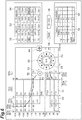
position move button 64 receives movement of the display position of theoperation section 60 on thetouch panel 41. The operator can move theoperation section 60 to any position in the screen by touching the display-position move button 64. In default settings, as depicted inFIG. 9 , theoperation section 60 is displayed in an upper-right area of the two-dimensional field 51 in a manner in which part thereof lies out of the area. - When
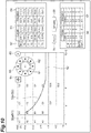
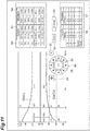
portions 52a corresponding to the neps N1 and N2 and the slubs S1 and S2 in theclearing limit 52 are displayed in an enlarged manner, theoperation section 60 is displayed in an upper-right area of the two-dimensional field 51 in a manner in which part thereof lies out of the area as depicted inFIG. 10 . Ifportions 52a corresponding to the long yarn L and the thin yarn T2 in theclearing limit 52 are displayed in an enlarged manner, when theportion 52a corresponding to the long yarn L has been selected, theoperation section 60 is displayed in an lower-right area of the two-dimensional field 51 in a manner in which part thereof lies out of the area as depicted inFIG. 11 . If theportions 52a corresponding to the long yarn L and the thin yarn T2 in theclearing limit 52 are displayed in an enlarged manner, when theportion 52a corresponding to the thin yarn T2 has been selected, theoperation section 60 is displayed in an upper-right area of the two-dimensional field 51 in a manner in which part thereof lies out of the area as depicted inFIG. 12 . - In the
machine control device 4, when at least oneportion 52a in thecurrent clearing limit 52 has been changed, a clearing simulation can be performed. The following describes the clearing simulation with reference toFIG. 13 . - Based on the yarn defect data stored in the
storage 43 and theclearing limit 52 before being changed (i.e., the current clearing limit) (portions indicated by the continuous line and the dashed line inFIG. 13 ), theprocessor 42 calculates a first yarn processing result, and causes thetouch panel 41 to display the first yarn processing result. Theprocessor 42 causes the first yarn processing result to be displayed as a yarn processing result based on theclearing limit 52 before being changed in acurrent result column 56. Based on the yarn defect data stored in thestorage 43 and theclearing limit 52 changed (portions indicated by the continuous line and the dashed and single-dotted line inFIG. 13 ), theprocessor 42 calculates a second yarn processing result, and causes thetouch panel 41 to display the second yarn processing result. Theprocessor 42 causes the second yarn processing result to be displayed as a yarn processing result based on theclearing limit 52 changed in asimulation result column 57. - In the
current result column 56, as the first yarn processing result, the number (n) of removed yarn defects and the converted number (/100 km) of removed yarn defects per unit length (herein, 100 kilometers) are displayed for the respective channels. The number (n) of removed yarn defects in thecurrent result column 56 is the measured number of yarn defects that have been removed, and corresponds to the number of dots of yarn defects having values within an area on the side opposite to the specified yarn thickness side (the side of the abscissa in which the thickness of the yarn defect is 0%) with respect to theclearing limit 52 before being changed. The number (n) of removed yarn defects may be converted into a number per unit time (e.g., 1 hour), and this converted number of removed yarn defects may be displayed in thecurrent result column 56. In thecurrent result column 56, as the first yarn processing result, either one of the number of removed yarn defects and the converted number of removed yarn defects per unit length may be displayed. - Similarly, in the
simulation result column 57, as the second yarn processing result, the number (n) of removed yarn defects and the converted number (/100 km) of removed yarn defects per unit length (herein, 100 kilometers) are displayed for the respective channels. The number (n) of removed yarn defects in thesimulation result column 57 is a predicted number based on the measured number of yarn defects, and corresponds to the number of dots of yarn defects having values within an area on the side opposite to the specified yarn thickness side (the side of the abscissa in which the thickness of the yarn defect is 0%) with respect to theclearing limit 52 changed. The number (n) of removed yarn defects may be converted into a number per unit time (e.g., 1 hour), and this converted number of removed yarn defects may be displayed in thesimulation result column 57. In thesimulation result column 57, as the second yarn processing result, either one of the number of removed yarn defects and the converted number of removed yarn defects per unit length may be displayed. In thesimulation result column 57, the amount of increase or decrease of the second yarn processing result from the first yarn processing result may be displayed. - In the example depicted in
FIG. 13 ,portions 52a corresponding to the nep N2 and the slub S1 in theclearing limit 52 have been selected with theclearing limit 52 orbuttons 55, and theseportions 52a have been moved downward by the predetermined amount with the operation section 60 (see the current set-value column 53 and the simulation set-value column 54). As a simulation result when theclearing limit 52 has been changed in this manner, the numbers of removed yarn defects for the nep N and the slub S have increased (see thecurrent result column 56 and the simulation result column 57). This clearing simulation is started when the operator touches asimulation button 58, and is ended when the operator touches again thesimulation button 58. Areset button 59 is a button configured to receive cancellation (reset) of setting (during simulation) of changing theclearing limit 52. Thesimulation button 58 and thereset button 59 do not have to be provided. In this case, when theclearing limit 52 has been changed, the second yarn processing result may be automatically (without waiting for another instruction by the operator) displayed. When the operator has touched a newly provided enter button (not depicted), theclearing limit 52 changed through simulation may be set as anew clearing limit 52. - In a row titled "CLASS" in the
current result column 56 and thesimulation result column 57, the number of removed yarn defects when what is called "class cut" is performed is displayed. The class cut is to remove yarn defects having values within an area that is selected from among a plurality of areas (classes) constituting the two-dimensional field 51. In a row titled "Sum" in thecurrent result column 56 and thesimulation result column 57, the sum of the numbers (n) of removed yarn defects and the sum of the numbers (/100 km) of removed yarn defects per unit length are displayed. Theclearing limit 52 may be configured to be changed in response to input of the number of removed yarn defects per unit length (e.g., 100 kilometers). In this case, theclearing limit 52 may be configured to be finely adjusted by operating theoperation section 60 after atemporary clearing limit 52 depending on the number of removed yarn defects per unit length is displayed. - The
processor 42 sets theclearing limit 52 before being changed or theclearing limit 52 changed as anew clearing limit 52. This setting of theclearing limit 52 is performed when the operator who has viewed the clearing simulation result touches a button (not depicted) for selecting theclearing limit 52 before being changed or theclearing limit 52 changed. - Changing of the
clearing limit 52 and displaying of theclearing limit 52 changed are functions of a first mode that theprocessor 42 has. Theprocessor 42 has a second mode in addition to the first mode. The second mode is a mode of changing theclearing limit 52 so as to remove yarn defects corresponding to an area touched among the areas constituting the two-dimensional field 51, and causing thetouch panel 41 to display theclearing limit 52 changed. For example, as depicted inFIG. 14 , when the class D1 has been touched in the secondmode, theprocessor 42 changes the part D1a of theclearing limit 52 so as to remove yarn defects having values within the class D1. - Alternatively, the second mode may be a mode of changing the
clearing limit 52 so as not to remove yarn defects corresponding to an area touched among the areas constituting the two-dimensional field 51, and causing thetouch panel 41 to display theclearing limit 52 changed. In this case, for example, as depicted inFIG. 14 , when the class D0 has been touched in the second mode, theprocessor 42 changes the part D0a of theclearing limit 52 so as not to remove yarn defects having values within the class D0. - As described in the foregoing, with the
machine control device 4, at least oneportion 52a among theportions 52a constituting theclearing limit 52 can be selected, and the selectedportion 52a can be moved. Theoperation section 60 that moves the selectedportion 52a indicates the moving directions for theclearing limit 52. This allows the operator to intuitively move the selectedportion 52a in a desired moving direction with theoperation section 60. Thus, with themachine control device 4, at least oneportion 52a among theportions 52a constituting theclearing limit 52 can be easily and appropriately changed. In other words, with themachine control device 4, at least one portion of theclearing limit 52 can be easily and appropriately changed. - In the
machine control device 4, theclearing limit 52 displayed by thetouch panel 41 receives selection of aportion 52a that has been touched among theportions 52a. This allows the operator to easily select a desiredportion 52a in theclearing limit 52. - In the
machine control device 4, theprocessor 42 causes thetouch panel 41 to display the selectedportion 52a such that theportion 52a becomes identifiable. This allows the operator to grasp whether the desiredportion 52a in theclearing limit 52 has been selected correctly. - In the
machine control device 4, theclearing limit 52 includes theportions 52a, and receives selection of at least oneportion 52a. This allows the operator to easily select a desired portion from among theportions 52a that are divided in advance. - In the
machine control device 4, each of theportions 52a is set depending on the type of the yarn defect. This allows one portion of theclearing limit 52 to be easily selected and changed depending on the type of the yarn defect. - In the
machine control device 4, thebuttons 55 that are displayed separately from theclearing limit 52 by thetouch panel 41 receive selection of aportion 52a corresponding to abutton 55 that has been touched among thebuttons 55. This allows the operator to easily select a desiredportion 52a of theclearing limit 52 even amongportions 52a of theclearing limit 52 that are finely displayed. - In the
machine control device 4, theprocessor 42 causes thetouch panel 41 to display the selectedbutton 55 such that thebutton 55 becomes identifiable. This allows the operator to grasp whether the desiredportion 52a in theclearing limit 52 has been selected correctly. - In the
machine control device 4, thetouch panel 41 displays theoperation section 60. This enables theoperation section 60 to be provided to the operator at appropriate timing, thereby eliminating the need to provide anadditional operation section 60. - In the
machine control device 4, theprocessor 42 causes thetouch panel 41 to display theoperation section 60 when selection of aportion 52a has been received. This can prevent theoperation section 60 from occupying a display area of thetouch panel 41 during a period of time other than when theclearing limit 52 is changed. - In the
machine control device 4, theprocessor 42 causes thetouch panel 41 to display theoperation section 60 such that the operation section does not overlap the selectedportion 52a. This allows the operator to operate theoperation section 60 while visually checking the selectedportion 52a. - In the
machine control device 4, theoperation section 60 includes the moving-direction instruction buttons 61 that indicates a plurality of moving directions at intervals of a predetermined angle and receives selection of a moving direction thereamong. This allows the operator to intuitively grasp the moving directions and operate theoperation section 60. - In the
machine control device 4, theoperation section 60 includes the moving-amount change button 62 that receives change of a predetermined amount. This allows the operator to move the selectedportion 52a by a large amount or to move the selected portion by a small amount. - In the
machine control device 4, theoperation section 60 includes the display cancelbutton 63 that receives cancellation of display of theoperation section 60 on thetouch panel 41. This allows the operator to easily change the state in which theclearing limit 52 has been selected back to the state in which the clearing limit has not been selected. - In the
machine control device 4, theoperation section 60 includes the display-position move button 64 that receives movement of the display position of theoperation section 60 on thetouch panel 41. This allows the operator to move theoperation section 60 to any position in the display area of thetouch panel 41 to check an area hidden by theoperation section 60 in the display area. - In the
machine control device 4, theprocessor 42 has: the first mode of changing theclearing limit 52 as described above and causing thetouch panel 41 to display theclearing limit 52 changed; and the second mode of changing theclearing limit 52 so as to remove or not to remove the yarn defect corresponding to an area touched among a plurality of areas constituting the two-dimensional field 51 and causing thetouch panel 41 to display theclearing limit 52 changed. This allows the operator to change theclearing limit 52 with theoperation section 60, and also allows the operator to change theclearing limit 52 on the basis of area designation in the two-dimensional field 51. - In the
machine control device 4, theprocessor 42 may cause thetouch panel 41 to display theclearing limit 52 changed and also theclearing limit 52 before being changed. This allows the operator to compare theclearing limit 52 changed with theclearing limit 52 before being changed. - In the
machine control device 4, theprocessor 42 acquires yarn defect data indicating the length and the thickness of the yarn defect, calculates a first yarn processing result based on the yarn defect data and theclearing limit 52 before being changed, calculates a second yarn processing result based on the yarn defect data and theclearing limit 52 changed, and causes thetouch panel 41 to display the first yarn processing result and the second yarn processing result. This allows the operator to compare the first yarn processing result with the second yarn processing result to evaluate each of theclearing limit 52 before being changed and theclearing limit 52 changed. - In the
machine control device 4, theprocessor 42 sets theclearing limit 52 before being changed or theclearing limit 52 changed as anew clearing limit 52. This allows the operator to set theclearing limit 52 before being changed or theclearing limit 52 changed as anew clearing limit 52. - The
yarn winding machine 1 includes: theyarn supplying section 21 that supplies yarn; the windingsection 24 that winds the yarn and forms a package; theyarn monitoring section 22 that monitors the yarn between theyarn supplying section 21 and the windingsection 24, and detects a yarn defect; theyarn joining section 23 that, when the yarn has been cut to remove the yarn defect detected by theyarn monitoring section 22, performs splicing operation of splicing the yarn on theyarn supplying section 21 side and the yarn on the windingsection 24 side; and themachine control device 4. Theyarn winding machine 1 includes themachine control device 4 described above, and thus can remove a yarn defect appropriately. - Although one embodiment of the present disclosure has been described above, the clearing-limit setting device and the yarn winding machine of the present disclosure are not limited to the embodiment.
- In the embodiment, the
clearing limit 52 and thebuttons 55 displayed by thetouch panel 41 function as the first input section that receives selection of at least oneportion 52a among theportions 52a constituting theclearing limit 52. However, separately from thetouch panel 41, a first input section including a mechanical button may be provided. - In the embodiment, the
operation section 60 displayed by thetouch panel 41 functions as the second input section that indicates a plurality of moving directions for theclearing limit 52 and receives selection of a moving direction thereamong. However, separately from thetouch panel 41, a second input section including a mechanical button and a lever may be provided. - In the embodiment, the
portions 52a constituting theclearing limit 52 correspond to the respective channels. However, theportions 52a may correspond to units other than the channels. - In the embodiment, the
machine control device 4 of theyarn winding machine 1 functions as the clearing-limit setting device. However, for example, a management device located separately from theyarn winding machine 1 may function as the clearing-limit setting device. At a machine end portion of theyarn winding machine 1, beside themachine control device 4, a clearing setting device dedicated to theyarn monitoring section 22 may be provided. - The
processor 42 may also acquire waveform data output from thedetection device 22a of theyarn monitoring section 22, in addition to acquiring yarn defect data from thecontrol device 22b of theyarn monitoring section 22. Alternatively, theprocessor 42 may acquire only waveform data output from thedetection device 22a of theyarn monitoring section 22, without acquiring yarn defect data from thecontrol device 22b of theyarn monitoring section 22. In this case, theprocessor 42 can calculate yarn defect data based on the acquired waveform data. - In the
current result column 56 and thesimulation result column 57, the amount of production may be displayed together with the number of removed yarn defects. When the target number of removed yarn defects or the target amount of production has been input, theclearing limit 52 corresponding to this number or amount may be displayed, and then theclearing limit 52 may be able to be finely adjusted by operating theoperation section 60. As a selecting method for selecting aportion 52a that may be changed in theclearing limit 52, theclearing limit 52 may be touched, or the corresponding button 55maybe touched. All portions of theclearing limit 52 maybe selected. - The
processor 42 may have: the first mode of changing theclearing limit 52 as described above and causing thetouch panel 41 to display theclearing limit 52 changed; and a second mode of causing thetouch panel 41 to display an area touched among a plurality of areas constituting the two-dimensional field 51 such that whether to remove or not to remove a yarn defect corresponding to the touched area becomes distinguishable. This allows the operator to change theclearing limit 52 with theoperation section 60, and also allows the operator to change a clearing area on the basis of area designation in the two-dimensional field 51. - If the clearing-limit setting device has the above-described function of setting the clearing limit, the clearing-limit setting device does not have to have the above-described function of performing the clearing simulation. Alternatively, the clearing-limit setting device may have the above-described function of performing the clearing simulation as an additional function. In this case also, at least one
portion 52a among theportions 52a constituting theclearing limit 52 can be easily and appropriately changed, and thus the clearing-limit setting device and the yarn winding machine of the present disclosure are significantly effective. - In the embodiment, the
clearing limit 52 is divided (segmented) into theportions 52a in advance, and at least oneportion 52a among theportions 52a is selectable by the operator. However, at least one portion ofclearing limit 52 may be selectable by the operator without dividing theclearing limit 52 in advance. For example, at least one portion of theclearing limit 52 may be selectable when the operator inputs with an input section a numerical range (e.g., at least one of the upper limit and the lower limit of at least one of thickness and length) of theclearing limit 52. Alternatively, at least one portion of theclearing limit 52 may be selectable when the operator touches part of theclearing limit 52 in a tracing manner on thetouch panel 41. - The at least one portion of the
clearing limit 52 selection of which the first input section receives may be one continuous portion, or may be two or more portions located separately from each other. When theclearing limit 52 is divided into theportions 52a in advance, the at least one portion may be one portion, may be two or more portions continuously located, or may be two or more portions located separately from each other. - At least some parts of the embodiment and modifications described above may be optionally used in combination.
Claims (17)
- A clearing-limit setting device (4) comprising:a display unit (41) that displays, in a two-dimensional field (51) having coordinate axes respectively representing length and thickness of a yarn defect, a clearing limit (52) that is a borderline whether the yarn defect needs to be removed;a first input section (52, 55) that receives selection of at least one portion (52a) of the clearing limit (52);a second input section (60) that indicates a plurality of moving directions for the clearing limit (52) and receives selection of a moving direction thereamong; anda processor (42) that changes the clearing limit (52) such that the at least one portion (52a) selected with the first input section (52, 55) moves in the moving direction selected with the second input section (60) by a predetermined amount, and causes the display unit (41) to display the clearing limit (52) changed.
- The clearing-limit setting device (4) according to claim 1, wherein the first input section (52, 55) includes the clearing limit (52) displayed by the display unit (41) and receives selection of at least one portion (52a) that has been touched in the clearing limit (52).
- The clearing-limit setting device (4) according to claim 1 or 2, wherein the processor (42) causes the display unit (41) to display the at least one portion (52a) selected with the first input section (52, 55) such that the at least one portion (52a) becomes identifiable.
- The clearing-limit setting device (4) according to any one of claims 1 to 3, wherein
the clearing limit (52) includes a plurality of portions (52a), and
the first input section (52, 55) receives selection of at least one portion (52a) among the portions (52a). - The clearing-limit setting device (4) according to claim 4, wherein each of the portions (52a) is set depending on the type of the yarn defect.
- The clearing-limit setting device (4) according to claim 4 or 5, wherein
the display unit (41) displays a plurality of buttons (55) respectively corresponding to the portions (52a) separately from the clearing limit (52), and
the first input section (52, 55) includes the buttons (55) displayed by the display unit (41) and receives selection of a portion (52a) corresponding to a button (55) that has been touched among the buttons (55). - The clearing-limit setting device (4) according to claim 6, wherein the processor (42) causes the display unit (41) to display the button (55) selected with the first input section (52, 55) such that the button (55) becomes identifiable.
- The clearing-limit setting device (4) according to any one of claims 1 to 7, wherein the second input section (60) is an operation section (60) displayed by the display unit (41).
- The clearing-limit setting device (4) according to claim 8, wherein the processor (42) causes the display unit (41) to display the operation section (60) when the first input section (52, 55) has received selection of the at least one portion (52a).
- The clearing-limit setting device (4) according to claim 8 or 9, wherein the processor (42) causes the display unit (41) to display the operation section (60) such that the operation section (60) does not overlap the at least one portion (52a) selected with the first input section (52, 55).
- The clearing-limit setting device (4) according to any one of claims 8 to 10, wherein the operation section (60) includes a moving-direction instruction button (61) that indicates a plurality of moving directions at intervals of a predetermined angle and receives selection of a moving direction thereamong.
- The clearing-limit setting device (4) according to any one of claims 8 to 11, wherein the operation section (60) further includes a moving-amount change button (62) that receives change of the predetermined amount.
- The clearing-limit setting device (4) according to any one of claims 1 to 12, wherein the processor (42) has:a first mode of changing the clearing limit (52) with the first input section (52, 55) and the second input section (60) and causing the display unit (41) to display the clearing limit (52) changed; anda second mode of changing the clearing limit (52) so as to remove or not to remove the yarn defect corresponding to an area touched among a plurality of areas constituting the two-dimensional field (51) and causing the display unit (41) to display the clearing limit (52) changed.
- The clearing-limit setting device (4) according to any one of claims 1 to 12, wherein the processor (42) has:a first mode of changing the clearing limit (52) with the first input section (52, 55) and the second input section (60) and causing the display unit (41) to display the clearing limit (52) changed; anda second mode of causing the display unit (41) to display an area touched among a plurality of areas constituting the two-dimensional field (51) such that whether to remove or not to remove the yarn defect corresponding to the area touched becomes distinguishable.
- The clearing-limit setting device (4) according to any one of claims 1 to 14, wherein the processor (42) causes the display unit (41) to display the clearing limit (52) changed and also the clearing limit (52) before being changed.
- The clearing-limit setting device (4) according to any one of claims 1 to 15, wherein the processor (42) acquires yarn defect data indicating the length and the thickness of the yarn defect, calculates a first yarn processing result based on the yarn defect data and the clearing limit (52) before being changed, calculates a second yarn processing result based on the yarn defect data and the clearing limit (52) changed, and causes the display unit (41) to display the first yarn processing result and the second yarn processing result.
- A yarn winding machine (1) comprising:a yarn supplying section (21) that supplies yarn;a winding section (24) that winds the yarn and forms a package;a yarn monitoring section (22) that monitors the yarn between the yarn supplying section (21) and the winding section (24), and detects a yarn defect;a yarn joining section (23) that, when the yarn has been cut to remove the yarn defect detected by the yarn monitoring section (22), performs splicing operation of splicing the yarn on the yarn supplying section (21) side and the yarn on the winding section (24) side; andthe clearing-limit setting device (4) according to any one of claims 1 to 16.
Applications Claiming Priority (1)
| Application Number | Priority Date | Filing Date | Title |
|---|---|---|---|
| JP2016167209A JP2018034917A (en) | 2016-08-29 | 2016-08-29 | Clearing limit setting device and yarn winding machine |
Publications (1)
| Publication Number | Publication Date |
|---|---|
| EP3290371A1 true EP3290371A1 (en) | 2018-03-07 |
Family
ID=59677083
Family Applications (1)
| Application Number | Title | Priority Date | Filing Date |
|---|---|---|---|
| EP17186623.9A Withdrawn EP3290371A1 (en) | 2016-08-29 | 2017-08-17 | Clearing-limit setting device and yarn winding machine |
Country Status (3)
| Country | Link |
|---|---|
| EP (1) | EP3290371A1 (en) |
| JP (1) | JP2018034917A (en) |
| CN (1) | CN107794738A (en) |
Cited By (1)
| Publication number | Priority date | Publication date | Assignee | Title |
|---|---|---|---|---|
| EP3653553A1 (en) * | 2018-11-19 | 2020-05-20 | Murata Machinery, Ltd. | Production volume simulation apparatus and predicted production volume calculation method |
Citations (4)
| Publication number | Priority date | Publication date | Assignee | Title |
|---|---|---|---|---|
| EP1295835A2 (en) * | 2001-08-28 | 2003-03-26 | Rieter Ingolstadt Spinnereimaschinenbau AG | Method for setting a clearing limit line in an electronic yarn clearer |
| JP2007211363A (en) | 2006-02-08 | 2007-08-23 | Murata Mach Ltd | Method for determining clearing of yarn defect and device for processing yarn |
| DE102008037758A1 (en) * | 2008-08-14 | 2010-02-18 | Oerlikon Textile Gmbh & Co. Kg | Method for quality monitoring of longitudinally moving yarn at workplace of textile machine manufacturing cross-coil, involves measuring errors in yarn using tester and evaluation device |
| CH707250A2 (en) * | 2012-11-26 | 2014-05-30 | Uster Technologies Ag | Method for establishing clearing limits on electronic cleaning system for elongated textile test material e.g. yarn, involves automatically adjusting computed clearing limit in response to question provided by input unit |
Family Cites Families (4)
| Publication number | Priority date | Publication date | Assignee | Title |
|---|---|---|---|---|
| EP0439767B1 (en) * | 1990-01-26 | 1996-02-14 | Zellweger Luwa Ag | Method for evaluating the quality of yarns and apparatus for implementing said method |
| CH680803A5 (en) * | 1990-01-26 | 1992-11-13 | Zellweger Uster Ag | |
| CN101310180B (en) * | 2005-11-18 | 2013-05-08 | 乌斯特技术股份公司 | A method for measuring the characteristics of floral yarn |
| JP2015132029A (en) * | 2014-01-15 | 2015-07-23 | 村田機械株式会社 | Yarn processing prediction device, yarn processing apparatus, and yarn processing prediction method |
-
2016
- 2016-08-29 JP JP2016167209A patent/JP2018034917A/en active Pending
-
2017
- 2017-08-17 EP EP17186623.9A patent/EP3290371A1/en not_active Withdrawn
- 2017-08-25 CN CN201710742669.1A patent/CN107794738A/en active Pending
Patent Citations (4)
| Publication number | Priority date | Publication date | Assignee | Title |
|---|---|---|---|---|
| EP1295835A2 (en) * | 2001-08-28 | 2003-03-26 | Rieter Ingolstadt Spinnereimaschinenbau AG | Method for setting a clearing limit line in an electronic yarn clearer |
| JP2007211363A (en) | 2006-02-08 | 2007-08-23 | Murata Mach Ltd | Method for determining clearing of yarn defect and device for processing yarn |
| DE102008037758A1 (en) * | 2008-08-14 | 2010-02-18 | Oerlikon Textile Gmbh & Co. Kg | Method for quality monitoring of longitudinally moving yarn at workplace of textile machine manufacturing cross-coil, involves measuring errors in yarn using tester and evaluation device |
| CH707250A2 (en) * | 2012-11-26 | 2014-05-30 | Uster Technologies Ag | Method for establishing clearing limits on electronic cleaning system for elongated textile test material e.g. yarn, involves automatically adjusting computed clearing limit in response to question provided by input unit |
Non-Patent Citations (1)
| Title |
|---|
| "Uster (CH)", 31 March 2003, article USTER TECHNOLOGIES AG: "Handbuch Uster Quantum Expert, Kapitel 6.9 : Reinigereinstellungen mit CAY", pages: 6 - 70, XP055621838 * |
Cited By (1)
| Publication number | Priority date | Publication date | Assignee | Title |
|---|---|---|---|---|
| EP3653553A1 (en) * | 2018-11-19 | 2020-05-20 | Murata Machinery, Ltd. | Production volume simulation apparatus and predicted production volume calculation method |
Also Published As
| Publication number | Publication date |
|---|---|
| CN107794738A (en) | 2018-03-13 |
| JP2018034917A (en) | 2018-03-08 |
Similar Documents
| Publication | Publication Date | Title |
|---|---|---|
| CN103628200A (en) | Textile machine | |
| CH709125B1 (en) | Device for predicting the processing of a yarn, device for processing a yarn and method for forecasting the processing of a yarn. | |
| JPS6314096B2 (en) | ||
| JP2018193198A (en) | Productive capacity display controller and method and automatic winder | |
| EP2671832B1 (en) | Yarn winding device | |
| TR201807072T4 (en) | A SPINNING STATION FITTED WITH THREAD CLEANER AND A SPINNING MACHINE AND A METHOD FOR OPERATING A SPINNING STATION. | |
| JP2018111553A (en) | Yarn information acquiring device, yarn winding machine and textile machine system | |
| CN103510217A (en) | Textile machinery and periodic unevenness detecting method therein | |
| EP3276348A1 (en) | Yarn analyzing device and spinning machine | |
| CH709205A2 (en) | Status display device of a yarn, a yarn processing device and method of the state of a yarn display. | |
| JP3861644B2 (en) | Yarn winding machine | |
| JP2018034917A (en) | Clearing limit setting device and yarn winding machine | |
| JP2007211363A (en) | Method for determining clearing of yarn defect and device for processing yarn | |
| JP2018178282A (en) | Yarn defect display device and yarn processing device | |
| CN108622737B (en) | Yarn clearing threshold setting device and yarn winding machine | |
| CN118773784A (en) | Detection and processing device, production line and detection and processing method | |
| EP3549892A1 (en) | Yarn winding machine | |
| CN110155809B (en) | Yarn clearing threshold setting device and yarn winding machine | |
| EP3378815B1 (en) | Yarn winding machine | |
| EP3587636A1 (en) | Periodic unevenness detecting method, textile processing system, spinning machine, and periodic unevenness detecting program | |
| EP3653553B1 (en) | Production volume simulation apparatus and predicted production volume calculation method | |
| JP2026068847A (en) | Textile machinery systems, control methods, and programs | |
| JP2017052587A (en) | Setting device | |
| CN110431099B (en) | Condition display device and yarn winding machine | |
| CN119100206A (en) | Fiber Machinery Systems |
Legal Events
| Date | Code | Title | Description |
|---|---|---|---|
| PUAI | Public reference made under article 153(3) epc to a published international application that has entered the european phase |
Free format text: ORIGINAL CODE: 0009012 |
|
| STAA | Information on the status of an ep patent application or granted ep patent |
Free format text: STATUS: THE APPLICATION HAS BEEN PUBLISHED |
|
| AK | Designated contracting states |
Kind code of ref document: A1 Designated state(s): AL AT BE BG CH CY CZ DE DK EE ES FI FR GB GR HR HU IE IS IT LI LT LU LV MC MK MT NL NO PL PT RO RS SE SI SK SM TR |
|
| AX | Request for extension of the european patent |
Extension state: BA ME |
|
| STAA | Information on the status of an ep patent application or granted ep patent |
Free format text: STATUS: REQUEST FOR EXAMINATION WAS MADE |
|
| 17P | Request for examination filed |
Effective date: 20180903 |
|
| RBV | Designated contracting states (corrected) |
Designated state(s): AL AT BE BG CH CY CZ DE DK EE ES FI FR GB GR HR HU IE IS IT LI LT LU LV MC MK MT NL NO PL PT RO RS SE SI SK SM TR |
|
| STAA | Information on the status of an ep patent application or granted ep patent |
Free format text: STATUS: EXAMINATION IS IN PROGRESS |
|
| 17Q | First examination report despatched |
Effective date: 20190918 |
|
| STAA | Information on the status of an ep patent application or granted ep patent |
Free format text: STATUS: THE APPLICATION IS DEEMED TO BE WITHDRAWN |
|
| 18D | Application deemed to be withdrawn |
Effective date: 20210429 |