EP3290280B1 - Pluralité de valves-relais ainsi que système de freinage pneumatique pourvu d'au moins une pluralité de valves-relais - Google Patents
Pluralité de valves-relais ainsi que système de freinage pneumatique pourvu d'au moins une pluralité de valves-relais Download PDFInfo
- Publication number
- EP3290280B1 EP3290280B1 EP17184329.5A EP17184329A EP3290280B1 EP 3290280 B1 EP3290280 B1 EP 3290280B1 EP 17184329 A EP17184329 A EP 17184329A EP 3290280 B1 EP3290280 B1 EP 3290280B1
- Authority
- EP
- European Patent Office
- Prior art keywords
- valve
- control
- piston
- multiple relay
- relay valve
- Prior art date
- Legal status (The legal status is an assumption and is not a legal conclusion. Google has not performed a legal analysis and makes no representation as to the accuracy of the status listed.)
- Revoked
Links
Images


Classifications
-
- B—PERFORMING OPERATIONS; TRANSPORTING
- B60—VEHICLES IN GENERAL
- B60T—VEHICLE BRAKE CONTROL SYSTEMS OR PARTS THEREOF; BRAKE CONTROL SYSTEMS OR PARTS THEREOF, IN GENERAL; ARRANGEMENT OF BRAKING ELEMENTS ON VEHICLES IN GENERAL; PORTABLE DEVICES FOR PREVENTING UNWANTED MOVEMENT OF VEHICLES; VEHICLE MODIFICATIONS TO FACILITATE COOLING OF BRAKES
- B60T15/00—Construction arrangement, or operation of valves incorporated in power brake systems and not covered by groups B60T11/00 or B60T13/00
- B60T15/02—Application and release valves
- B60T15/18—Triple or other relay valves which allow step-wise application or release and which are actuated by brake-pipe pressure variation to connect brake cylinders or equivalent to compressed air or vacuum source or atmosphere
Definitions
- the present invention relates to a multiple relay valve for relay actuation of a fluid line with multiple circuit protection for a commercial vehicle, in particular for an agricultural utility vehicle and a pneumatic brake system for a commercial vehicle.
- the EP 2 581 280 A1 discloses a double relay valve for compressed air systems with a plurality of concentric valve pistons arranged in the valve housing.
- the WO 01/89900 A2 discloses a relay valve having a relay valve function and a modulation valve function having a plurality of concentric valve pistons disposed in the valve housing.
- Another relay valve according to the prior art is in the document CN 101 992 765 B disclosed.
- the Mehrfachrelaisventil having at least a first control terminal for connection to a first brake circuit and at least one second control terminal for connection to a second brake circuit, wherein the fluid line is released, if at least one the two control ports are acted upon with an opening pressure and wherein the fluid line is locked when both control ports are subjected to a closing pressure, wherein the first control port is in fluid communication with a first valve chamber and the second control port is in fluid communication with a second valve chamber Valve chamber and the second valve chamber are fluid-tightly separated from each other by at least two seals and wherein between the seals in the assembled state, a secondary vent is arranged.
- the invention is based on the basic idea that a relay valve with double or multiple control is provided, wherein a control terminal with a first brake circuit, for example, the left rear brake circuit and the other control terminal connected to the right rear brake circuit or connected.
- a control terminal with a first brake circuit for example, the left rear brake circuit and the other control terminal connected to the right rear brake circuit or connected.
- This makes it possible to separately control the rear left and right wheels on the rear axle and pass the higher of the two control pressures to the front axle.
- the design of the multiple relay valve also makes it possible to allow a separate control of the left and right wheels of the axle of the two service brake circuits, wherein the respective other axis receives the higher of the two brake pressures.
- it is possible to release the fluid line of the pneumatic brake system by acting with only one control port with the opening pressure and thereby actuate the brake.
- the opening pressure is to be understood as meaning a pressure which serves to open the relay valve and bears against one of the two control connections or the control connections.
- a closing pressure is to be understood as meaning a pressure which is applied to the control terminals when the relay valve is closed or should be closed.
- both control connections must be assigned the closing pressure.
- the closing pressure can already be that the two control ports are depressurized or fall below a threshold that is no longer for the operation the control connections is sufficient. Due to the fluid-tight separation of the first valve chamber with the second valve chamber, it is possible to enable a separation of the two brake circuits of the pneumatic brake system.
- the first valve chamber may be associated with the first brake circuit and the second valve chamber with the second brake circuit.
- the multiple relay valve may be a double relay valve.
- the fluid line is a compressed air line.
- the fluid line may be the main compressed air line of the pneumatic brake system.
- a first control valve piston and in the second valve chamber, a second control valve piston may be arranged, wherein the first control valve piston actuated at applied opening control pressure at the first control port, the second control valve piston, in particular mechanically actuated. This can easily be ensured that when the first control port is acted upon by an opening pressure, in any case, both the first control valve piston and the second control valve piston are actuated, even if no opening pressure is applied to the second control port.
- the at least two seals can be arranged. This facilitates assembly and further leads to a secure sealing function of the seals.
- the two seals can be designed as radial seals. These may be, for example, vulcanized seals or O-rings. By radial seals a simple configuration of the valve piston is made possible.
- the multiple relay valve may have a housing and the seals may be made against the housing. This makes it easy and reliable to realize a seal between the first valve chamber and the second valve chamber.
- the secondary ventilation is arranged in the housing. This allows an arrangement and maintenance of the secondary vent, because it is so well accessible both during manufacture and during operation.
- the secondary vent is designed as a bore in the housing. This allows easy positioning of the secondary vent in the housing. In addition, this makes the production easier.
- a relay piston which serves to block and release the fluid line.
- the relay piston can be actuated by the second control valve piston.
- the relay piston is mechanically actuated by the second control valve piston.
- the relay piston is displaced such that it releases the fluid line.
- the relay piston may further have a passage for a vent port. This makes it possible to enable a vent function via the multiple relay valve.
- the present invention relates to a pneumatic brake system for a commercial vehicle, in particular an agricultural utility vehicle with at least one multiple relay valve.
- the first valve chamber may be in communication with a first service brake circuit of the pneumatic brake system and the second valve chamber may be in communication with a second service brake circuit of the pneumatic brake system.
- the pneumatic separation of the first service brake circuit and the second service brake circuit can be effected by the at least two seals.
- first service brake circuit and the second service brake circuit are each assigned to a wheel of the rear axle of the commercial vehicle and that the fluid line is used to control a brake of at least one wheel of a front axle of the utility vehicle.
- Fig. 1 shows a schematic sectional view of an embodiment of a multiple relay valve 10 according to the invention, embodied here as a double relay valve 10.
- the double relay valve 10 has a housing 12.
- a first valve chamber 14 and a second valve chamber 16 is provided in the housing 12.
- the first valve chamber 14 is delimited by the first control valve piston 18 from the second valve chamber 16, so that the first valve chamber 14 is bounded by a part of the inner wall of the housing 12 and the control valve piston 18.
- the second valve chamber 16 is bounded by a part of the inner housing wall of the housing 12, by the side of the control valve piston 18 facing away from the first valve chamber 14 and by the side of the second control valve piston 20 facing the first control valve piston 18.
- the control valve piston 18 has two radial seals 22 and 24 which are held in a radial collar 26 of the control valve piston 18.
- the control valve piston 18 further has a central circular plate 28, which is integrally formed integrally with the radial collar 26, so that overall a plate-like structure for the first control valve piston 18 results.
- the second control valve piston 20 has a centrally disposed, tubular cylinder portion 30 which in the mounted state on the first control valve piston 18 side facing a cylindrical, closed Actuating portion 38 and on the side facing away from the first control valve piston 18 in the mounted state an open tube cylinder portion 40 which rises from the piston plate 32 as well as the section 38 out.
- the second control valve piston 20 has a radial collar 34, in which, however, a single radial seal 36 is held.
- the double relay valve 10 further has a substantially cylindrical relay piston 39, which has a T-shaped cross-section, axial sealing collar 43 with an axial seal 44 arranged thereon.
- This axial seal 44 is intended to be made sealing against a housing portion of the housing 12.
- the relay piston 39 also has a radial seal 46, which is also employed in a sealing manner against a housing section of the housing 12.
- a return spring 48 is further provided, which is employed against the Axialbund 43 on one side and against a housing portion of the Genosueses 12 on the other side.
- the return spring 48 is guided over a radial guide section 50.
- the housing 12 further has a secondary vent 52, which is realized by a bore through the housing wall of the housing 12.
- the secondary vent 52 is arranged such that in the assembled state, the secondary vent 52 is always located in the annular gap which is located between the seals 22 and 24.
- Fig. 1 the secondary vent on the outer wall of the housing 12 is shown.
- any other arrangement of secondary ventilation is conceivable, for example, inwards via the main ventilation.
- Fig. 1 shows the double relay valve 10 in the non-actuated state and Fig. 2 the double relay valve 10 in the actuated state.
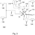
- Fig. 3 shows a first embodiment of a pneumatic brake system 100 for a commercial vehicle, here an agricultural utility vehicle.
- the relay valve 10 serves to block or release the fluid line 110, which is a pneumatic line.
- the first valve chamber 14 is in communication with a control port 41 of the double relay valve 10.
- the second valve chamber 16 communicates with a second control port 42 of the double relay valve 10 in connection.
- the ports 1 and 2 of the fluid line 110 are in the Fig. 1 . 2 and 3 each shown and the terminals 1 and 2 are connected depending on the position of the relay piston 39 either together (see. Fig. 2 ) or separated from each other (cf. Fig. 1 ).
- the pneumatic brake system 100 further includes a first brake circuit 112 for controlling a brake device 122, here a spring brake cylinder 122 of the right wheel of the rear axle.
- the second brake circuit 114 is used to control a brake device 124, here a spring brake cylinder 124 of the left wheel of the rear axle of the commercial vehicle.
- the first brake circuit 112 is associated with a first compressor 116 or a compressed air source 116, while the second brake circuit 114, a second compressed air source 118 is assigned.
- a foot brake valve 120 is provided, wherein by pressing the foot brake valve 120, the compressed air source 116 via the terminals 11 and 21, the first brake circuit 112 so that the spring brake cylinder 122 is actuated.
- the actuation of the foot brake valve 120 further causes the compressed air source 118 via the terminals 12 and 22, the spring brake cylinder 124 is actuated.
- the fluid line 110 supplies the two brake devices 128, 130, in this case spring brake cylinders 128, 130 of the front axle, with compressed air from the compressed air source 126 or compressor 126.
- the double relay valve 10 and the pneumatic brake system 100 shown can be described as follows:
- the double relay valve 10 can be switched such that the fluid line 110 or the fluid connection between the port 1 and the port 2 is released when at least one of the two control ports 41 or 42 is acted upon by an opening pressure, so that either at least the second Control valve piston 20 moves in the direction of the relay piston 39 to actuate this, and thus to release the fluid connection between the first control port 1 and the second Steueran gleichs 2 of the fluid line 110.
- both control terminals 41 and 42 are acted upon by a closing pressure, that is not printed, is via the return spring 48, the relay piston 39th reset, so that the axial seal 44 is made against the housing extension of the housing 12 and thereby the fluid connection between the terminal 1 and the terminal 2 is no longer released.
- the still binding in the port 2 pressure can escape via the vent port 3 and be discharged to the atmosphere.
- the left and right wheel or the associated brake of the rear axle of the two service brake circuits 112, 114 are each controlled separately and the front axle or there located spring brake cylinders 122, 124 receive the higher of the two brake pressures.
- the front axle or there located spring brake cylinders 122, 124 receive the higher of the two brake pressures.
- the control terminal 41 of the double relay valve 10 is connected to the first service brake circuit 112 of the right rear wheel and the control terminal 42 to the second service brake circuit 114 of the left rear wheel.
- the two service brake circuits 112 and 114 are double insulated in the double relay valve 10 by means of the two separate seals 22, 24 and also equipped with the secondary ventilation 52.
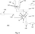
- Fig. 4 shows an alternative to the embodiment according to. Fig. 3 .
- the pneumatic brake system 100 has substantially all the structural and functional features of the pneumatic brake system 100 according to Fig. 3 and as described above.
- the only difference is essentially that the two service brake circuits 112 'and 114' can be controlled separately via a double pedal on the foot brake valve 120 '.
- the pneumatic brake system 100 'thus also has a fluid line 110', service brake circuits 112 ', 114', compressors 116 ', 118', 126 'or compressed air source 116', 118 ', 126' and brake devices 122 ', 124', 128 '. or spring brake cylinder 122 ', 124', 128 'on.
Landscapes
- Engineering & Computer Science (AREA)
- Transportation (AREA)
- Mechanical Engineering (AREA)
- Valves And Accessory Devices For Braking Systems (AREA)
Claims (16)
- Vanne (10) relais multiple pour l'actionnement en relais d'un conduit (110) pour du fluide d'un système (100) de frein pneumatique, ayant de multiples sécurités de circuit pour un véhicule utilitaire, notamment pour un véhicule utilitaire utilisé en agriculture, comprenant au moins un premier raccord (41) de commande de raccordement à un premier circuit (112) de frein et comprenant au moins un deuxième raccord (42) de commande de raccordement à un deuxième circuit (114) de frein, le conduit (110) pour du fluide étant dégagé, si au moins l'un des deux raccords (41, 42) de commande est soumis à une pression d'ouverture, et le conduit (110) pour du fluide étant obturé, si les deux raccords (41, 42) de commande sont soumis à une pression de fermeture, le premier raccord (41) de commande étant en communication fluidique avec une première chambre (14) de vanne et le deuxième raccord (42) de commande étant en communication fluidique avec une deuxième chambre (16) de vanne, la première chambre (14) de vanne et la deuxième chambre (16) de vanne étant séparées d'une manière étanche au fluide l'une de l'autre par au moins deux garnitures (22, 24) d'étanchéité
et caractérisée en ce qu'
une purge (52) secondaire est montée, à l'état monté, entre les deux garnitures (22, 24) d'étanchéité. - Vanne (10) relais multiple suivant la revendication 1,
caractérisée en ce que
le conduit (110) pour du fluide est un conduit pour de l'air comprimé. - Vanne (10) relais multiple suivant la revendication 1 ou la revendication 2,
caractérisée en ce que,
dans la première chambre (14) de vanne, est monté un premier piston (18) de vanne de commande et, dans la deuxième chambre (16) de vanne, est monté un deuxième piston (20) de vanne de commande, le premier piston (18) de vanne de commande actionnant, notamment mécaniquement, le deuxième piston (20) de vanne de commande, lorsqu'une pression de commande d'ouverture est appliquée au premier raccord (41) de commande. - Vanne (10) relais multiple suivant la revendication 3,
caractérisée en ce que
les au moins deux garnitures (22, 24) d'étanchéité sont montées sur le premier piston (18) de vanne de commande. - Vanne (10) relais multiple suivant l'une des revendications précédentes,
caractérisée en ce que
les garnitures (22, 24) d'étanchéité sont des garnitures (22, 24) d'étanchéité radiales. - Vanne (10) relais multiple suivant l'une des revendications précédentes,
caractérisée en ce que
la vanne (10) relais multiple a un corps (12) et en ce que les garnitures (22, 24) d'étanchéité sont mises sur le corps. - Vanne (10) relais multiple suivant la revendication 6,
caractérisée en ce que
la purge (52) secondaire est disposée dans le corps (12). - Vanne (10) relais multiple suivant la revendication 6 ou la revendication 7,
caractérisée en ce que
la purge (52) secondaire est constituée sous la forme d'un trou dans le corps (12). - Vanne (10) relais multiple suivant l'une des revendications précédentes,
caractérisée en ce qu'
il est prévu un piston (39) relais, qui sert à obturer et à dégager le conduit (110) pour du fluide. - Vanne (10) relais multiple suivant la revendication 9,
caractérisée en ce que
le piston (39) relais peut être actionné, notamment mécaniquement, par le deuxième piston (20) de vanne de commande. - Vanne (10) relais multiple suivant l'une des revendications 8 à 10,
caractérisée en ce que
le piston (39) relais a une traversée pour un raccord de purge. - Système (100) de frein pneumatique d'un véhicule utilitaire, notamment d'un véhicule utilitaire utilisé en agriculture, comprenant au moins une vanne (10) relais multiple suivant l'une des revendications précédentes.
- Système (100) de frein pneumatique suivant la revendication 12,
caractérisé en ce que
la première chambre (14) de vanne est en liaison avec un premier circuit (112) de frein de service du système (100) de frein pneumatique et en ce que la deuxième chambre (16) de vanne est en liaison avec un deuxième circuit (114) de frein de service du système (100) de frein pneumatique. - Système (100) de frein pneumatique suivant la revendication 13,
caractérisé en ce que
la séparation pneumatique du premier circuit (112) de frein de service et du deuxième circuit (114) de frein de service est obtenue par les au moins deux garnitures (22, 24) d'étanchéité. - Système (100) de frein pneumatique suivant l'une des revendications 12 à 14,
caractérisé en ce qu'
une fuite de l'une des deux garnitures (22, 24) d'étanchéité provoque une sortie d'air comprimé par la purge (52) secondaire, la purge (52) secondaire étant telle qu'une sortie d'air comprimé par la purge (52) d'air secondaire donne un bruit de fuite audible. - Système (100) de frein pneumatique suivant l'une des revendications 13 à 15,
caractérisé en ce que
le premier circuit (112) de frein de service et le deuxième circuit (114) de frein de service sont associés chacun à une roue de l'essieu arrière du véhicule utilitaire et en ce que le conduit (110) pour un fluide est utilisé pour commander un frein d'au moins une roue d'un essieu avant du véhicule utilitaire.
Applications Claiming Priority (1)
| Application Number | Priority Date | Filing Date | Title |
|---|---|---|---|
| DE102016114831.8A DE102016114831A1 (de) | 2016-08-10 | 2016-08-10 | Mehrfachrelaisventil sowie pneumatisches Bremssystem mit wenigstens einem Mehrfachrelaisventil |
Publications (2)
| Publication Number | Publication Date |
|---|---|
| EP3290280A1 EP3290280A1 (fr) | 2018-03-07 |
| EP3290280B1 true EP3290280B1 (fr) | 2019-05-29 |
Family
ID=59506193
Family Applications (1)
| Application Number | Title | Priority Date | Filing Date |
|---|---|---|---|
| EP17184329.5A Revoked EP3290280B1 (fr) | 2016-08-10 | 2017-08-01 | Pluralité de valves-relais ainsi que système de freinage pneumatique pourvu d'au moins une pluralité de valves-relais |
Country Status (3)
| Country | Link |
|---|---|
| EP (1) | EP3290280B1 (fr) |
| DE (1) | DE102016114831A1 (fr) |
| ES (1) | ES2744101T3 (fr) |
Families Citing this family (2)
| Publication number | Priority date | Publication date | Assignee | Title |
|---|---|---|---|---|
| CN108944886B (zh) * | 2018-08-20 | 2024-09-10 | 山东安顺制动系统有限公司 | 一种制动阀 |
| DE102021103053B3 (de) * | 2021-02-10 | 2022-02-03 | Knorr-Bremse Systeme für Nutzfahrzeuge GmbH | Relaisventilvorrichtung und Bremsvorrichtung für ein Fahrzeug mit einer solchen Relaisventilvorrichtung |
Citations (15)
| Publication number | Priority date | Publication date | Assignee | Title |
|---|---|---|---|---|
| DE2251479A1 (de) | 1972-10-20 | 1974-05-02 | Bosch Gmbh Robert | Anhaengersteuerventil |
| DE2431259A1 (de) | 1974-06-28 | 1976-01-08 | Dewandre Co Ltd C | Anhaengerbremssteuerventil |
| DE2615893A1 (de) | 1974-04-24 | 1977-10-20 | Bosch Gmbh Robert | Anhaenger-steuerventil |
| EP0223935A1 (fr) | 1985-11-29 | 1987-06-03 | WABCO Westinghouse Fahrzeugbremsen GmbH | Valve de commande de pression de freinage commandés par deux circuits |
| EP0308375A1 (fr) | 1987-09-15 | 1989-03-22 | Bendix Heavy Vehicle Systems Italia S.P.A. | Valve utilisable notamment dans le système de freinage pneumatique d'un tracteur pour contrôler le freinage du véhicule tracté |
| DE3818688A1 (de) | 1988-06-01 | 1989-12-07 | Knorr Bremse Ag | Vorrichtung zur festhaftverhinderung von dichtelementen an nur gelegentlich bewegten ventilkolben fuer druckmittelbetaetigte bremsanlagen von fahrzeugen, insbesondere nutzfahrzeugen |
| EP0411355A1 (fr) | 1989-07-31 | 1991-02-06 | Grau Gmbh | Valve relais, commandeé par deux circuits, en particulier valve de contrôle ou commande pour remorques, pour systèmes pneumatiques de freinage de véhicules |
| DE3929936A1 (de) | 1989-09-08 | 1991-03-21 | Grau Gmbh | Ueber zwei kreise ansteuerbares relaisventil, insbesondere anhaengersteuer- oder anhaengerbremsventil, fuer druckluftbremsanlagen von kraftfahrzeugen |
| DE3929934A1 (de) | 1989-09-08 | 1991-03-21 | Grau Gmbh | Mindestens einkreisig ansteuerbares relaisventil mit einstellbarer voreilung |
| DE19504394C1 (de) | 1995-02-10 | 1996-03-07 | Wabco Gmbh | Druckmittelbetätigte Fahrzeugbremsanlage |
| US5700063A (en) | 1995-02-10 | 1997-12-23 | Wabco Gmbh | Pressure medium actuated vehicle braking system |
| EP1069017A2 (fr) | 1999-07-12 | 2001-01-17 | KNORR-BREMSE SYSTEME FÜR NUTZFAHRZEUGE GmbH | Système de freinage pour véhicules actionné par fluide sous pression |
| EP1069016A2 (fr) | 1999-07-16 | 2001-01-17 | KNORR-BREMSE SYSTEME FÜR NUTZFAHRZEUGE GmbH | Installation de freinage actionnée par moyen de pression |
| DE19954568A1 (de) | 1999-11-12 | 2001-05-17 | Knorr Bremse Systeme | Druckmittelbetätigte Fahrzeugbremsanlage |
| US20140103237A1 (en) | 2011-05-13 | 2014-04-17 | Knorr-Bremse Systeme für Nutzfahrzeuge GmbH | Parking brake device |
Family Cites Families (8)
| Publication number | Priority date | Publication date | Assignee | Title |
|---|---|---|---|---|
| JPS577945B2 (fr) * | 1973-08-22 | 1982-02-13 | ||
| FR2347243A2 (fr) * | 1974-04-24 | 1977-11-04 | Bosch Gmbh Robert | Soupape de commande de remorque |
| IT1144088B (it) * | 1980-05-02 | 1986-10-29 | Magneti Marelli Spa | Servodistributore a doppio comando per impianti di frenatura pneumatica di veicoli |
| US6769744B2 (en) | 2000-05-25 | 2004-08-03 | Bendix Commercial Vehicle Systems Llc | Spring brake modulating relay valve |
| US7048000B2 (en) * | 2004-03-03 | 2006-05-23 | Haldex Brake Corporation | Pressure reducing valve |
| CN201816583U (zh) | 2010-06-09 | 2011-05-04 | 瑞立集团瑞安汽车零部件有限公司 | 一种双继动阀集成阀 |
| CN101992765B (zh) * | 2010-11-18 | 2012-10-03 | 三一汽车起重机械有限公司 | 双控继动阀及具有该继动阀的气压制动系统 |
| CN204110020U (zh) * | 2014-08-07 | 2015-01-21 | 王松元 | 差动式继动阀 |
-
2016
- 2016-08-10 DE DE102016114831.8A patent/DE102016114831A1/de not_active Withdrawn
-
2017
- 2017-08-01 ES ES17184329T patent/ES2744101T3/es active Active
- 2017-08-01 EP EP17184329.5A patent/EP3290280B1/fr not_active Revoked
Patent Citations (15)
| Publication number | Priority date | Publication date | Assignee | Title |
|---|---|---|---|---|
| DE2251479A1 (de) | 1972-10-20 | 1974-05-02 | Bosch Gmbh Robert | Anhaengersteuerventil |
| DE2615893A1 (de) | 1974-04-24 | 1977-10-20 | Bosch Gmbh Robert | Anhaenger-steuerventil |
| DE2431259A1 (de) | 1974-06-28 | 1976-01-08 | Dewandre Co Ltd C | Anhaengerbremssteuerventil |
| EP0223935A1 (fr) | 1985-11-29 | 1987-06-03 | WABCO Westinghouse Fahrzeugbremsen GmbH | Valve de commande de pression de freinage commandés par deux circuits |
| EP0308375A1 (fr) | 1987-09-15 | 1989-03-22 | Bendix Heavy Vehicle Systems Italia S.P.A. | Valve utilisable notamment dans le système de freinage pneumatique d'un tracteur pour contrôler le freinage du véhicule tracté |
| DE3818688A1 (de) | 1988-06-01 | 1989-12-07 | Knorr Bremse Ag | Vorrichtung zur festhaftverhinderung von dichtelementen an nur gelegentlich bewegten ventilkolben fuer druckmittelbetaetigte bremsanlagen von fahrzeugen, insbesondere nutzfahrzeugen |
| EP0411355A1 (fr) | 1989-07-31 | 1991-02-06 | Grau Gmbh | Valve relais, commandeé par deux circuits, en particulier valve de contrôle ou commande pour remorques, pour systèmes pneumatiques de freinage de véhicules |
| DE3929936A1 (de) | 1989-09-08 | 1991-03-21 | Grau Gmbh | Ueber zwei kreise ansteuerbares relaisventil, insbesondere anhaengersteuer- oder anhaengerbremsventil, fuer druckluftbremsanlagen von kraftfahrzeugen |
| DE3929934A1 (de) | 1989-09-08 | 1991-03-21 | Grau Gmbh | Mindestens einkreisig ansteuerbares relaisventil mit einstellbarer voreilung |
| DE19504394C1 (de) | 1995-02-10 | 1996-03-07 | Wabco Gmbh | Druckmittelbetätigte Fahrzeugbremsanlage |
| US5700063A (en) | 1995-02-10 | 1997-12-23 | Wabco Gmbh | Pressure medium actuated vehicle braking system |
| EP1069017A2 (fr) | 1999-07-12 | 2001-01-17 | KNORR-BREMSE SYSTEME FÜR NUTZFAHRZEUGE GmbH | Système de freinage pour véhicules actionné par fluide sous pression |
| EP1069016A2 (fr) | 1999-07-16 | 2001-01-17 | KNORR-BREMSE SYSTEME FÜR NUTZFAHRZEUGE GmbH | Installation de freinage actionnée par moyen de pression |
| DE19954568A1 (de) | 1999-11-12 | 2001-05-17 | Knorr Bremse Systeme | Druckmittelbetätigte Fahrzeugbremsanlage |
| US20140103237A1 (en) | 2011-05-13 | 2014-04-17 | Knorr-Bremse Systeme für Nutzfahrzeuge GmbH | Parking brake device |
Also Published As
| Publication number | Publication date |
|---|---|
| ES2744101T3 (es) | 2020-02-21 |
| DE102016114831A1 (de) | 2018-02-15 |
| EP3290280A1 (fr) | 2018-03-07 |
Similar Documents
| Publication | Publication Date | Title |
|---|---|---|
| EP3157789B1 (fr) | Valve-relais à double piston à fonction anti-compound | |
| EP3390177B1 (fr) | Unité soupape pour la modulation de pression dans un système de freinage à air comprimé | |
| EP2731839B1 (fr) | Installation de préparation d'air comprimé et procédé servant à faire fonctionner une installation de préparation d'air comprimé | |
| EP2058186A2 (fr) | Installation de frein pour une remorque d'un véhicule automobile | |
| EP3371018B1 (fr) | Soupape de limitation de pression | |
| EP2812219B1 (fr) | Cylindre de frein de service et de frein de stationnement combiné comprenant un piston de frein de stationnement commandé par la pression du frein de service | |
| EP3228512B1 (fr) | Clapet destiné à relâcher le frein de stationnement d'une remorque | |
| EP3256357B1 (fr) | Arrangement de frein de service avec soupape à relachement rapide | |
| EP3307594A1 (fr) | Système de frein pneumatique pour un véhicule tracté | |
| EP3290280B1 (fr) | Pluralité de valves-relais ainsi que système de freinage pneumatique pourvu d'au moins une pluralité de valves-relais | |
| EP3371019A1 (fr) | Soupape de limitation de pression | |
| EP3277551B1 (fr) | Dispositif à air comprimé pour des véhicules équipés d'une soupape à double relais | |
| WO2017060128A1 (fr) | Dispositif de freinage électropneumatique équipé d'un module de régulation de pression relié par deux clapets à deux réservoirs d'air comprimé | |
| EP3429898B1 (fr) | Soupape de relâchement de frein de stationnement pour un véhicule tracté | |
| DE102009057890B4 (de) | Anhängersteuermodul zur Bremssteuerung eines Anhängers und Verfahren zum Betreiben des Anhängersteuermoduls | |
| EP3286050B1 (fr) | Arrangement de vanne de contrôle pour un frein de parking pour véhicules et arrangement de frein de parking pour véhicules | |
| DE10133440C2 (de) | Bremsanlage mit elektropneumatischem Modulator | |
| DE102017011548A1 (de) | Pneumatische Ventilanordnung für Anhängerfahrzeug | |
| EP3507148A1 (fr) | Système de freinage pneumatique pour un véhicule tracté | |
| DE102018002488B4 (de) | Bremssystem eines Fahrzeugzuges | |
| DE102010007410B3 (de) | Zweikreisiges Fußbremsventil für eine druckmittelbetätigte Bremsanlage eines Fahrzeugs | |
| DE102022113470B3 (de) | Sicherheitsventilanordnung und Aktorsystem |
Legal Events
| Date | Code | Title | Description |
|---|---|---|---|
| PUAI | Public reference made under article 153(3) epc to a published international application that has entered the european phase |
Free format text: ORIGINAL CODE: 0009012 |
|
| STAA | Information on the status of an ep patent application or granted ep patent |
Free format text: STATUS: THE APPLICATION HAS BEEN PUBLISHED |
|
| AK | Designated contracting states |
Kind code of ref document: A1 Designated state(s): AL AT BE BG CH CY CZ DE DK EE ES FI FR GB GR HR HU IE IS IT LI LT LU LV MC MK MT NL NO PL PT RO RS SE SI SK SM TR |
|
| AX | Request for extension of the european patent |
Extension state: BA ME |
|
| STAA | Information on the status of an ep patent application or granted ep patent |
Free format text: STATUS: REQUEST FOR EXAMINATION WAS MADE |
|
| 17P | Request for examination filed |
Effective date: 20180907 |
|
| RBV | Designated contracting states (corrected) |
Designated state(s): AL AT BE BG CH CY CZ DE DK EE ES FI FR GB GR HR HU IE IS IT LI LT LU LV MC MK MT NL NO PL PT RO RS SE SI SK SM TR |
|
| GRAP | Despatch of communication of intention to grant a patent |
Free format text: ORIGINAL CODE: EPIDOSNIGR1 |
|
| STAA | Information on the status of an ep patent application or granted ep patent |
Free format text: STATUS: GRANT OF PATENT IS INTENDED |
|
| INTG | Intention to grant announced |
Effective date: 20181217 |
|
| GRAS | Grant fee paid |
Free format text: ORIGINAL CODE: EPIDOSNIGR3 |
|
| GRAA | (expected) grant |
Free format text: ORIGINAL CODE: 0009210 |
|
| STAA | Information on the status of an ep patent application or granted ep patent |
Free format text: STATUS: THE PATENT HAS BEEN GRANTED |
|
| AK | Designated contracting states |
Kind code of ref document: B1 Designated state(s): AL AT BE BG CH CY CZ DE DK EE ES FI FR GB GR HR HU IE IS IT LI LT LU LV MC MK MT NL NO PL PT RO RS SE SI SK SM TR |
|
| REG | Reference to a national code |
Ref country code: GB Ref legal event code: FG4D Free format text: NOT ENGLISH |
|
| REG | Reference to a national code |
Ref country code: CH Ref legal event code: EP |
|
| REG | Reference to a national code |
Ref country code: AT Ref legal event code: REF Ref document number: 1138078 Country of ref document: AT Kind code of ref document: T Effective date: 20190615 |
|
| REG | Reference to a national code |
Ref country code: DE Ref legal event code: R096 Ref document number: 502017001426 Country of ref document: DE |
|
| REG | Reference to a national code |
Ref country code: IE Ref legal event code: FG4D Free format text: LANGUAGE OF EP DOCUMENT: GERMAN |
|
| REG | Reference to a national code |
Ref country code: NL Ref legal event code: MP Effective date: 20190529 |
|
| REG | Reference to a national code |
Ref country code: LT Ref legal event code: MG4D |
|
| PG25 | Lapsed in a contracting state [announced via postgrant information from national office to epo] |
Ref country code: FI Free format text: LAPSE BECAUSE OF FAILURE TO SUBMIT A TRANSLATION OF THE DESCRIPTION OR TO PAY THE FEE WITHIN THE PRESCRIBED TIME-LIMIT Effective date: 20190529 Ref country code: NO Free format text: LAPSE BECAUSE OF FAILURE TO SUBMIT A TRANSLATION OF THE DESCRIPTION OR TO PAY THE FEE WITHIN THE PRESCRIBED TIME-LIMIT Effective date: 20190829 Ref country code: SE Free format text: LAPSE BECAUSE OF FAILURE TO SUBMIT A TRANSLATION OF THE DESCRIPTION OR TO PAY THE FEE WITHIN THE PRESCRIBED TIME-LIMIT Effective date: 20190529 Ref country code: LT Free format text: LAPSE BECAUSE OF FAILURE TO SUBMIT A TRANSLATION OF THE DESCRIPTION OR TO PAY THE FEE WITHIN THE PRESCRIBED TIME-LIMIT Effective date: 20190529 Ref country code: HR Free format text: LAPSE BECAUSE OF FAILURE TO SUBMIT A TRANSLATION OF THE DESCRIPTION OR TO PAY THE FEE WITHIN THE PRESCRIBED TIME-LIMIT Effective date: 20190529 Ref country code: PT Free format text: LAPSE BECAUSE OF FAILURE TO SUBMIT A TRANSLATION OF THE DESCRIPTION OR TO PAY THE FEE WITHIN THE PRESCRIBED TIME-LIMIT Effective date: 20190930 Ref country code: AL Free format text: LAPSE BECAUSE OF FAILURE TO SUBMIT A TRANSLATION OF THE DESCRIPTION OR TO PAY THE FEE WITHIN THE PRESCRIBED TIME-LIMIT Effective date: 20190529 |
|
| PGFP | Annual fee paid to national office [announced via postgrant information from national office to epo] |
Ref country code: TR Payment date: 20190826 Year of fee payment: 3 Ref country code: FR Payment date: 20190822 Year of fee payment: 3 Ref country code: ES Payment date: 20190919 Year of fee payment: 3 Ref country code: DE Payment date: 20190822 Year of fee payment: 3 |
|
| PG25 | Lapsed in a contracting state [announced via postgrant information from national office to epo] |
Ref country code: GR Free format text: LAPSE BECAUSE OF FAILURE TO SUBMIT A TRANSLATION OF THE DESCRIPTION OR TO PAY THE FEE WITHIN THE PRESCRIBED TIME-LIMIT Effective date: 20190830 Ref country code: BG Free format text: LAPSE BECAUSE OF FAILURE TO SUBMIT A TRANSLATION OF THE DESCRIPTION OR TO PAY THE FEE WITHIN THE PRESCRIBED TIME-LIMIT Effective date: 20190829 Ref country code: LV Free format text: LAPSE BECAUSE OF FAILURE TO SUBMIT A TRANSLATION OF THE DESCRIPTION OR TO PAY THE FEE WITHIN THE PRESCRIBED TIME-LIMIT Effective date: 20190529 Ref country code: RS Free format text: LAPSE BECAUSE OF FAILURE TO SUBMIT A TRANSLATION OF THE DESCRIPTION OR TO PAY THE FEE WITHIN THE PRESCRIBED TIME-LIMIT Effective date: 20190529 |
|
| PG25 | Lapsed in a contracting state [announced via postgrant information from national office to epo] |
Ref country code: RO Free format text: LAPSE BECAUSE OF FAILURE TO SUBMIT A TRANSLATION OF THE DESCRIPTION OR TO PAY THE FEE WITHIN THE PRESCRIBED TIME-LIMIT Effective date: 20190529 Ref country code: NL Free format text: LAPSE BECAUSE OF FAILURE TO SUBMIT A TRANSLATION OF THE DESCRIPTION OR TO PAY THE FEE WITHIN THE PRESCRIBED TIME-LIMIT Effective date: 20190529 Ref country code: DK Free format text: LAPSE BECAUSE OF FAILURE TO SUBMIT A TRANSLATION OF THE DESCRIPTION OR TO PAY THE FEE WITHIN THE PRESCRIBED TIME-LIMIT Effective date: 20190529 Ref country code: EE Free format text: LAPSE BECAUSE OF FAILURE TO SUBMIT A TRANSLATION OF THE DESCRIPTION OR TO PAY THE FEE WITHIN THE PRESCRIBED TIME-LIMIT Effective date: 20190529 Ref country code: SK Free format text: LAPSE BECAUSE OF FAILURE TO SUBMIT A TRANSLATION OF THE DESCRIPTION OR TO PAY THE FEE WITHIN THE PRESCRIBED TIME-LIMIT Effective date: 20190529 Ref country code: CZ Free format text: LAPSE BECAUSE OF FAILURE TO SUBMIT A TRANSLATION OF THE DESCRIPTION OR TO PAY THE FEE WITHIN THE PRESCRIBED TIME-LIMIT Effective date: 20190529 |
|
| REG | Reference to a national code |
Ref country code: DE Ref legal event code: R026 Ref document number: 502017001426 Country of ref document: DE |
|
| REG | Reference to a national code |
Ref country code: ES Ref legal event code: FG2A Ref document number: 2744101 Country of ref document: ES Kind code of ref document: T3 Effective date: 20200221 |
|
| PG25 | Lapsed in a contracting state [announced via postgrant information from national office to epo] |
Ref country code: SM Free format text: LAPSE BECAUSE OF FAILURE TO SUBMIT A TRANSLATION OF THE DESCRIPTION OR TO PAY THE FEE WITHIN THE PRESCRIBED TIME-LIMIT Effective date: 20190529 |
|
| PLBI | Opposition filed |
Free format text: ORIGINAL CODE: 0009260 |
|
| PLAX | Notice of opposition and request to file observation + time limit sent |
Free format text: ORIGINAL CODE: EPIDOSNOBS2 |
|
| 26 | Opposition filed |
Opponent name: WABCO EUROPE BVBA Effective date: 20200220 |
|
| PG25 | Lapsed in a contracting state [announced via postgrant information from national office to epo] |
Ref country code: PL Free format text: LAPSE BECAUSE OF FAILURE TO SUBMIT A TRANSLATION OF THE DESCRIPTION OR TO PAY THE FEE WITHIN THE PRESCRIBED TIME-LIMIT Effective date: 20190529 |
|
| PG25 | Lapsed in a contracting state [announced via postgrant information from national office to epo] |
Ref country code: SI Free format text: LAPSE BECAUSE OF FAILURE TO SUBMIT A TRANSLATION OF THE DESCRIPTION OR TO PAY THE FEE WITHIN THE PRESCRIBED TIME-LIMIT Effective date: 20190529 Ref country code: LU Free format text: LAPSE BECAUSE OF NON-PAYMENT OF DUE FEES Effective date: 20190801 Ref country code: MC Free format text: LAPSE BECAUSE OF FAILURE TO SUBMIT A TRANSLATION OF THE DESCRIPTION OR TO PAY THE FEE WITHIN THE PRESCRIBED TIME-LIMIT Effective date: 20190529 |
|
| REG | Reference to a national code |
Ref country code: BE Ref legal event code: MM Effective date: 20190831 |
|
| PG25 | Lapsed in a contracting state [announced via postgrant information from national office to epo] |
Ref country code: IE Free format text: LAPSE BECAUSE OF NON-PAYMENT OF DUE FEES Effective date: 20190801 |
|
| PG25 | Lapsed in a contracting state [announced via postgrant information from national office to epo] |
Ref country code: BE Free format text: LAPSE BECAUSE OF NON-PAYMENT OF DUE FEES Effective date: 20190831 |
|
| PGFP | Annual fee paid to national office [announced via postgrant information from national office to epo] |
Ref country code: IT Payment date: 20200831 Year of fee payment: 4 |
|
| REG | Reference to a national code |
Ref country code: DE Ref legal event code: R119 Ref document number: 502017001426 Country of ref document: DE |
|
| REG | Reference to a national code |
Ref country code: CH Ref legal event code: PL |
|
| PG25 | Lapsed in a contracting state [announced via postgrant information from national office to epo] |
Ref country code: CH Free format text: LAPSE BECAUSE OF NON-PAYMENT OF DUE FEES Effective date: 20200831 Ref country code: LI Free format text: LAPSE BECAUSE OF NON-PAYMENT OF DUE FEES Effective date: 20200831 |
|
| RDAF | Communication despatched that patent is revoked |
Free format text: ORIGINAL CODE: EPIDOSNREV1 |
|
| REG | Reference to a national code |
Ref country code: DE Ref legal event code: R103 Ref document number: 502017001426 Country of ref document: DE Ref country code: DE Ref legal event code: R064 Ref document number: 502017001426 Country of ref document: DE |
|
| PG25 | Lapsed in a contracting state [announced via postgrant information from national office to epo] |
Ref country code: CY Free format text: LAPSE BECAUSE OF FAILURE TO SUBMIT A TRANSLATION OF THE DESCRIPTION OR TO PAY THE FEE WITHIN THE PRESCRIBED TIME-LIMIT Effective date: 20190529 |
|
| PG25 | Lapsed in a contracting state [announced via postgrant information from national office to epo] |
Ref country code: IS Free format text: LAPSE BECAUSE OF FAILURE TO SUBMIT A TRANSLATION OF THE DESCRIPTION OR TO PAY THE FEE WITHIN THE PRESCRIBED TIME-LIMIT Effective date: 20190929 |
|
| PG25 | Lapsed in a contracting state [announced via postgrant information from national office to epo] |
Ref country code: FR Free format text: LAPSE BECAUSE OF NON-PAYMENT OF DUE FEES Effective date: 20200831 Ref country code: HU Free format text: LAPSE BECAUSE OF FAILURE TO SUBMIT A TRANSLATION OF THE DESCRIPTION OR TO PAY THE FEE WITHIN THE PRESCRIBED TIME-LIMIT; INVALID AB INITIO Effective date: 20170801 Ref country code: DE Free format text: LAPSE BECAUSE OF NON-PAYMENT OF DUE FEES Effective date: 20210302 Ref country code: MT Free format text: LAPSE BECAUSE OF FAILURE TO SUBMIT A TRANSLATION OF THE DESCRIPTION OR TO PAY THE FEE WITHIN THE PRESCRIBED TIME-LIMIT Effective date: 20190529 |
|
| RDAG | Patent revoked |
Free format text: ORIGINAL CODE: 0009271 |
|
| STAA | Information on the status of an ep patent application or granted ep patent |
Free format text: STATUS: PATENT REVOKED |
|
| REG | Reference to a national code |
Ref country code: CH Ref legal event code: PL |
|
| REG | Reference to a national code |
Ref country code: FI Ref legal event code: MGE |
|
| 27W | Patent revoked |
Effective date: 20210522 |
|
| GBPR | Gb: patent revoked under art. 102 of the ep convention designating the uk as contracting state |
Effective date: 20210522 |
|
| REG | Reference to a national code |
Ref country code: AT Ref legal event code: MA03 Ref document number: 1138078 Country of ref document: AT Kind code of ref document: T Effective date: 20210522 |
|
| PG25 | Lapsed in a contracting state [announced via postgrant information from national office to epo] |
Ref country code: TR Free format text: LAPSE BECAUSE OF NON-PAYMENT OF DUE FEES Effective date: 20200801 Ref country code: MK Free format text: LAPSE BECAUSE OF FAILURE TO SUBMIT A TRANSLATION OF THE DESCRIPTION OR TO PAY THE FEE WITHIN THE PRESCRIBED TIME-LIMIT Effective date: 20190529 |
|
| PG25 | Lapsed in a contracting state [announced via postgrant information from national office to epo] |
Ref country code: ES Free format text: LAPSE BECAUSE OF NON-PAYMENT OF DUE FEES Effective date: 20200802 |