EP3290280B1 - Multiple relay valve and pneumatic braking system with at least one multiple relay valve - Google Patents
Multiple relay valve and pneumatic braking system with at least one multiple relay valve Download PDFInfo
- Publication number
- EP3290280B1 EP3290280B1 EP17184329.5A EP17184329A EP3290280B1 EP 3290280 B1 EP3290280 B1 EP 3290280B1 EP 17184329 A EP17184329 A EP 17184329A EP 3290280 B1 EP3290280 B1 EP 3290280B1
- Authority
- EP
- European Patent Office
- Prior art keywords
- valve
- control
- piston
- multiple relay
- relay valve
- Prior art date
- Legal status (The legal status is an assumption and is not a legal conclusion. Google has not performed a legal analysis and makes no representation as to the accuracy of the status listed.)
- Revoked
Links
Images


Classifications
-
- B—PERFORMING OPERATIONS; TRANSPORTING
- B60—VEHICLES IN GENERAL
- B60T—VEHICLE BRAKE CONTROL SYSTEMS OR PARTS THEREOF; BRAKE CONTROL SYSTEMS OR PARTS THEREOF, IN GENERAL; ARRANGEMENT OF BRAKING ELEMENTS ON VEHICLES IN GENERAL; PORTABLE DEVICES FOR PREVENTING UNWANTED MOVEMENT OF VEHICLES; VEHICLE MODIFICATIONS TO FACILITATE COOLING OF BRAKES
- B60T15/00—Construction arrangement, or operation of valves incorporated in power brake systems and not covered by groups B60T11/00 or B60T13/00
- B60T15/02—Application and release valves
- B60T15/18—Triple or other relay valves which allow step-wise application or release and which are actuated by brake-pipe pressure variation to connect brake cylinders or equivalent to compressed air or vacuum source or atmosphere
Definitions
- the present invention relates to a multiple relay valve for relay actuation of a fluid line with multiple circuit protection for a commercial vehicle, in particular for an agricultural utility vehicle and a pneumatic brake system for a commercial vehicle.
- the EP 2 581 280 A1 discloses a double relay valve for compressed air systems with a plurality of concentric valve pistons arranged in the valve housing.
- the WO 01/89900 A2 discloses a relay valve having a relay valve function and a modulation valve function having a plurality of concentric valve pistons disposed in the valve housing.
- Another relay valve according to the prior art is in the document CN 101 992 765 B disclosed.
- the Mehrfachrelaisventil having at least a first control terminal for connection to a first brake circuit and at least one second control terminal for connection to a second brake circuit, wherein the fluid line is released, if at least one the two control ports are acted upon with an opening pressure and wherein the fluid line is locked when both control ports are subjected to a closing pressure, wherein the first control port is in fluid communication with a first valve chamber and the second control port is in fluid communication with a second valve chamber Valve chamber and the second valve chamber are fluid-tightly separated from each other by at least two seals and wherein between the seals in the assembled state, a secondary vent is arranged.
- the invention is based on the basic idea that a relay valve with double or multiple control is provided, wherein a control terminal with a first brake circuit, for example, the left rear brake circuit and the other control terminal connected to the right rear brake circuit or connected.
- a control terminal with a first brake circuit for example, the left rear brake circuit and the other control terminal connected to the right rear brake circuit or connected.
- This makes it possible to separately control the rear left and right wheels on the rear axle and pass the higher of the two control pressures to the front axle.
- the design of the multiple relay valve also makes it possible to allow a separate control of the left and right wheels of the axle of the two service brake circuits, wherein the respective other axis receives the higher of the two brake pressures.
- it is possible to release the fluid line of the pneumatic brake system by acting with only one control port with the opening pressure and thereby actuate the brake.
- the opening pressure is to be understood as meaning a pressure which serves to open the relay valve and bears against one of the two control connections or the control connections.
- a closing pressure is to be understood as meaning a pressure which is applied to the control terminals when the relay valve is closed or should be closed.
- both control connections must be assigned the closing pressure.
- the closing pressure can already be that the two control ports are depressurized or fall below a threshold that is no longer for the operation the control connections is sufficient. Due to the fluid-tight separation of the first valve chamber with the second valve chamber, it is possible to enable a separation of the two brake circuits of the pneumatic brake system.
- the first valve chamber may be associated with the first brake circuit and the second valve chamber with the second brake circuit.
- the multiple relay valve may be a double relay valve.
- the fluid line is a compressed air line.
- the fluid line may be the main compressed air line of the pneumatic brake system.
- a first control valve piston and in the second valve chamber, a second control valve piston may be arranged, wherein the first control valve piston actuated at applied opening control pressure at the first control port, the second control valve piston, in particular mechanically actuated. This can easily be ensured that when the first control port is acted upon by an opening pressure, in any case, both the first control valve piston and the second control valve piston are actuated, even if no opening pressure is applied to the second control port.
- the at least two seals can be arranged. This facilitates assembly and further leads to a secure sealing function of the seals.
- the two seals can be designed as radial seals. These may be, for example, vulcanized seals or O-rings. By radial seals a simple configuration of the valve piston is made possible.
- the multiple relay valve may have a housing and the seals may be made against the housing. This makes it easy and reliable to realize a seal between the first valve chamber and the second valve chamber.
- the secondary ventilation is arranged in the housing. This allows an arrangement and maintenance of the secondary vent, because it is so well accessible both during manufacture and during operation.
- the secondary vent is designed as a bore in the housing. This allows easy positioning of the secondary vent in the housing. In addition, this makes the production easier.
- a relay piston which serves to block and release the fluid line.
- the relay piston can be actuated by the second control valve piston.
- the relay piston is mechanically actuated by the second control valve piston.
- the relay piston is displaced such that it releases the fluid line.
- the relay piston may further have a passage for a vent port. This makes it possible to enable a vent function via the multiple relay valve.
- the present invention relates to a pneumatic brake system for a commercial vehicle, in particular an agricultural utility vehicle with at least one multiple relay valve.
- the first valve chamber may be in communication with a first service brake circuit of the pneumatic brake system and the second valve chamber may be in communication with a second service brake circuit of the pneumatic brake system.
- the pneumatic separation of the first service brake circuit and the second service brake circuit can be effected by the at least two seals.
- first service brake circuit and the second service brake circuit are each assigned to a wheel of the rear axle of the commercial vehicle and that the fluid line is used to control a brake of at least one wheel of a front axle of the utility vehicle.
- Fig. 1 shows a schematic sectional view of an embodiment of a multiple relay valve 10 according to the invention, embodied here as a double relay valve 10.
- the double relay valve 10 has a housing 12.
- a first valve chamber 14 and a second valve chamber 16 is provided in the housing 12.
- the first valve chamber 14 is delimited by the first control valve piston 18 from the second valve chamber 16, so that the first valve chamber 14 is bounded by a part of the inner wall of the housing 12 and the control valve piston 18.
- the second valve chamber 16 is bounded by a part of the inner housing wall of the housing 12, by the side of the control valve piston 18 facing away from the first valve chamber 14 and by the side of the second control valve piston 20 facing the first control valve piston 18.
- the control valve piston 18 has two radial seals 22 and 24 which are held in a radial collar 26 of the control valve piston 18.
- the control valve piston 18 further has a central circular plate 28, which is integrally formed integrally with the radial collar 26, so that overall a plate-like structure for the first control valve piston 18 results.
- the second control valve piston 20 has a centrally disposed, tubular cylinder portion 30 which in the mounted state on the first control valve piston 18 side facing a cylindrical, closed Actuating portion 38 and on the side facing away from the first control valve piston 18 in the mounted state an open tube cylinder portion 40 which rises from the piston plate 32 as well as the section 38 out.
- the second control valve piston 20 has a radial collar 34, in which, however, a single radial seal 36 is held.
- the double relay valve 10 further has a substantially cylindrical relay piston 39, which has a T-shaped cross-section, axial sealing collar 43 with an axial seal 44 arranged thereon.
- This axial seal 44 is intended to be made sealing against a housing portion of the housing 12.
- the relay piston 39 also has a radial seal 46, which is also employed in a sealing manner against a housing section of the housing 12.
- a return spring 48 is further provided, which is employed against the Axialbund 43 on one side and against a housing portion of the Genosueses 12 on the other side.
- the return spring 48 is guided over a radial guide section 50.
- the housing 12 further has a secondary vent 52, which is realized by a bore through the housing wall of the housing 12.
- the secondary vent 52 is arranged such that in the assembled state, the secondary vent 52 is always located in the annular gap which is located between the seals 22 and 24.
- Fig. 1 the secondary vent on the outer wall of the housing 12 is shown.
- any other arrangement of secondary ventilation is conceivable, for example, inwards via the main ventilation.
- Fig. 1 shows the double relay valve 10 in the non-actuated state and Fig. 2 the double relay valve 10 in the actuated state.
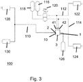
- Fig. 3 shows a first embodiment of a pneumatic brake system 100 for a commercial vehicle, here an agricultural utility vehicle.
- the relay valve 10 serves to block or release the fluid line 110, which is a pneumatic line.
- the first valve chamber 14 is in communication with a control port 41 of the double relay valve 10.
- the second valve chamber 16 communicates with a second control port 42 of the double relay valve 10 in connection.
- the ports 1 and 2 of the fluid line 110 are in the Fig. 1 . 2 and 3 each shown and the terminals 1 and 2 are connected depending on the position of the relay piston 39 either together (see. Fig. 2 ) or separated from each other (cf. Fig. 1 ).
- the pneumatic brake system 100 further includes a first brake circuit 112 for controlling a brake device 122, here a spring brake cylinder 122 of the right wheel of the rear axle.
- the second brake circuit 114 is used to control a brake device 124, here a spring brake cylinder 124 of the left wheel of the rear axle of the commercial vehicle.
- the first brake circuit 112 is associated with a first compressor 116 or a compressed air source 116, while the second brake circuit 114, a second compressed air source 118 is assigned.
- a foot brake valve 120 is provided, wherein by pressing the foot brake valve 120, the compressed air source 116 via the terminals 11 and 21, the first brake circuit 112 so that the spring brake cylinder 122 is actuated.
- the actuation of the foot brake valve 120 further causes the compressed air source 118 via the terminals 12 and 22, the spring brake cylinder 124 is actuated.
- the fluid line 110 supplies the two brake devices 128, 130, in this case spring brake cylinders 128, 130 of the front axle, with compressed air from the compressed air source 126 or compressor 126.
- the double relay valve 10 and the pneumatic brake system 100 shown can be described as follows:
- the double relay valve 10 can be switched such that the fluid line 110 or the fluid connection between the port 1 and the port 2 is released when at least one of the two control ports 41 or 42 is acted upon by an opening pressure, so that either at least the second Control valve piston 20 moves in the direction of the relay piston 39 to actuate this, and thus to release the fluid connection between the first control port 1 and the second Steueran gleichs 2 of the fluid line 110.
- both control terminals 41 and 42 are acted upon by a closing pressure, that is not printed, is via the return spring 48, the relay piston 39th reset, so that the axial seal 44 is made against the housing extension of the housing 12 and thereby the fluid connection between the terminal 1 and the terminal 2 is no longer released.
- the still binding in the port 2 pressure can escape via the vent port 3 and be discharged to the atmosphere.
- the left and right wheel or the associated brake of the rear axle of the two service brake circuits 112, 114 are each controlled separately and the front axle or there located spring brake cylinders 122, 124 receive the higher of the two brake pressures.
- the front axle or there located spring brake cylinders 122, 124 receive the higher of the two brake pressures.
- the control terminal 41 of the double relay valve 10 is connected to the first service brake circuit 112 of the right rear wheel and the control terminal 42 to the second service brake circuit 114 of the left rear wheel.
- the two service brake circuits 112 and 114 are double insulated in the double relay valve 10 by means of the two separate seals 22, 24 and also equipped with the secondary ventilation 52.
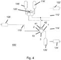
- Fig. 4 shows an alternative to the embodiment according to. Fig. 3 .
- the pneumatic brake system 100 has substantially all the structural and functional features of the pneumatic brake system 100 according to Fig. 3 and as described above.
- the only difference is essentially that the two service brake circuits 112 'and 114' can be controlled separately via a double pedal on the foot brake valve 120 '.
- the pneumatic brake system 100 'thus also has a fluid line 110', service brake circuits 112 ', 114', compressors 116 ', 118', 126 'or compressed air source 116', 118 ', 126' and brake devices 122 ', 124', 128 '. or spring brake cylinder 122 ', 124', 128 'on.
Description
Die vorliegende Erfindung betrifft ein Mehrfachrelaisventil zur Relaisbetätigung einer Fluidleitung mit mehrfacher Kreisabsicherung für ein Nutzfahrzeug, insbesondere für ein landwirtschaftlich genutztes Nutzfahrzeug sowie ein pneumatisches Bremssystem für ein Nutzfahrzeug.The present invention relates to a multiple relay valve for relay actuation of a fluid line with multiple circuit protection for a commercial vehicle, in particular for an agricultural utility vehicle and a pneumatic brake system for a commercial vehicle.
Nutzfahrzeuge mit pneumatischen Bremsanlagen können nach ECE R13 und EU 2015/68 mit zwei unabhängigen pneumatischen Bremskreisen bestückt werden, welche üblicherweise auf die Vorder-, respektive auf die Hinterachse wirken.Commercial vehicles with pneumatic brake systems can be fitted with two independent pneumatic brake circuits according to ECE R13 and EU 2015/68, which usually act on the front and rear axles.
Bei einigen Fahrzeugen, insbesondere bei landwirtschaftlichen Nutzfahrzeugen, ist es manchmal erwünscht, die Kreistrennung anders zu realisieren.In some vehicles, especially agricultural vehicles, it is sometimes desirable to realize the circular separation differently.
Die
Die
Es ist die Aufgabe der vorliegenden Erfindung, ein Mehrfachrelaisventil sowie ein pneumatisches Bremssystem der eingangs genannten Art in vorteilhafter Weise weiterzubilden, insbesondere dahingehend, eine Absicherung mehrerer Bremskreise mit einem Mehrfachrelaisventil zu realisieren und eine alternative Bremsansteuerung an den Achsen des Fahrzeugs zu realisieren.It is the object of the present invention to develop a multiple relay valve and a pneumatic brake system of the type mentioned in an advantageous manner, in particular to realize a hedge several brake circuits with a multiple relay valve and to realize an alternative brake control on the axles of the vehicle.
Diese Aufgabe wird erfindungsgemäß gelöst durch ein Mehrfachrelaisventil zur Relaisbetätigung einer Fluidleitung eines pneumatischen Bremssystems mit den Merkmalen des Anspruchs 1. Danach ist vorgesehen, dass ein Mehrfachrelaisventil zur Relaisbetätigung einer Fluidleitung eines pneumatischen Bremssystems mit mehrfacher Kreisabsicherung für ein Nutzfahrzeug bereitgestellt wird, wobei das Mehrfachrelaisventil wenigstens einen ersten Steueranschluss zum Anschluss an einen ersten Bremskreis und wenigstens einen zweiten Steueranschluss zum Anschluss an einen zweiten Bremskreis aufweist, wobei die Fluidleitung freigegeben ist, wenn zumindest einer der beiden Steueranschlüsse mit einem Öffnungsdruck beaufschlagt wird und wobei die Fluidleitung gesperrt ist, wenn beide Steueranschlüsse mit einem Schließdruck beaufschlagt sind, wobei der erste Steueranschluss mit einer ersten Ventilkammer in Fluidverbindung steht und der zweite Steueranschluss mit einer zweiten Ventilkammer in Fluidverbindung steht, wobei die erste Ventilkammer und die zweite Ventilkammer durch wenigstens zwei Dichtungen voneinander fluiddicht getrennt sind und wobei zwischen den Dichtungen im montierten Zustand eine Sekundärentlüftung angeordnet ist.This object is achieved by a multiple relay valve for relay actuation of a fluid line of a pneumatic brake system with the features of
Die Erfindung basiert auf dem Grundgedanken, dass ein Relaisventil mit doppelter bzw. mehrfacher Ansteuerung vorgesehen wird, wobei ein Steueranschluss mit einem ersten Bremskreis, beispielsweise dem linken hinteren Bremskreis und der andere Steueranschluss mit dem rechten hinteren Bremskreis verbindbar bzw. verbunden sind. Dadurch wird es möglich, die Räder hinten links und rechts an der Hinterachse separat anzusteuern und den höheren der beiden Steuerdrücke an die Vorderachse weiterzugeben. Die Ausgestaltung des Mehrfachrelaisventils ermöglicht es zudem, eine separate Ansteuerung des linken und rechten Rades der Achse von beiden Betriebsbremskreisen zu ermöglichen, wobei die jeweils andere Achse den höheren der beiden Bremsdrücke erhält. Außerdem ist es möglich, durch die Beaufschlagung mit nur eines Steueranschlusses mit dem Öffnungsdruck die Fluidleitung des pneumatischen Bremssystems freizugeben und hierdurch die Bremse zu betätigen. Als Öffnungsdruck soll ein Druck verstanden werden, der zum Öffnen des Relaisventils dient und an einem der beiden Steueranschlüsse oder den Steueranschlüssen anliegt. Als Schließdruck ist demgegenüber ein Druck zu verstehen, der an den Steueranschlüssen anliegt, wenn das Relaisventil geschlossen ist bzw. geschlossen werden soll. Für das Sperren der Fluidleitung müssen beide Steueranschlüsse mit dem Schließdruck beauftragt sein. Der Schließdruck kann bereits darin bestehen, dass die beiden Steueranschlüsse drucklos geschaltet sind oder unter einen Schwellwert fallen, der nicht mehr für die Betätigung der Steueranschlüsse ausreicht. Durch die fluiddichte Trennung der ersten Ventilkammer mit der zweiten Ventilkammer wird es möglich, eine Separierung der beiden Bremskreise des pneumatischen Bremssystems zu ermöglichen. So kann die erste Ventilkammer dem ersten Bremskreis zugeordnet sein und die zweite Ventilkammer dem zweiten Bremskreis. Dadurch, dass zwei Dichtungen vorgesehen sind, kann eine doppelte Kreistrennung zwischen zwei Betriebsbremskreisen, die mit dem Mehrfachrelaisventil getrennt sind, eingehalten werden. Mittels zweier separater Dichtungen wird eine doppelte Isolierung herbeigeführt. Im montierten Zustand kann zwischen den Dichtungen eine Sekundärentlüftung angeordnet sein. Mittels der Sekundärentlüftung kann erreicht werden, dass bei einem Versagen einer der beiden Dichtungen ein Druckluftaustritt durch die Sekundärentlüftung erfolgt, was mit einem höhrbaren Leckage-Geräusch einhergehen kann. Hierdurch wird es möglich, ein Versagen einer der Dichtungen einfach und zuverlässig erkennen zu können.The invention is based on the basic idea that a relay valve with double or multiple control is provided, wherein a control terminal with a first brake circuit, for example, the left rear brake circuit and the other control terminal connected to the right rear brake circuit or connected. This makes it possible to separately control the rear left and right wheels on the rear axle and pass the higher of the two control pressures to the front axle. The design of the multiple relay valve also makes it possible to allow a separate control of the left and right wheels of the axle of the two service brake circuits, wherein the respective other axis receives the higher of the two brake pressures. In addition, it is possible to release the fluid line of the pneumatic brake system by acting with only one control port with the opening pressure and thereby actuate the brake. The opening pressure is to be understood as meaning a pressure which serves to open the relay valve and bears against one of the two control connections or the control connections. In contrast, a closing pressure is to be understood as meaning a pressure which is applied to the control terminals when the relay valve is closed or should be closed. To lock the fluid line, both control connections must be assigned the closing pressure. The closing pressure can already be that the two control ports are depressurized or fall below a threshold that is no longer for the operation the control connections is sufficient. Due to the fluid-tight separation of the first valve chamber with the second valve chamber, it is possible to enable a separation of the two brake circuits of the pneumatic brake system. Thus, the first valve chamber may be associated with the first brake circuit and the second valve chamber with the second brake circuit. By providing two seals, dual circuit separation between two service brake circuits separated by the multiple relay valve can be maintained. By means of two separate seals a double insulation is brought about. In the assembled state, a secondary vent can be arranged between the seals. By means of the secondary venting can be achieved that in case of failure of one of the two seals a compressed air leakage occurs through the secondary vent, which may be accompanied by a hearing loss murmurable. This makes it possible to easily and reliably detect a failure of one of the seals.
Das Mehrfachrelaisventil kann ein Doppelrelaisventil sein.The multiple relay valve may be a double relay valve.
Es kann vorgesehen sein, dass die Fluidleitung eine Druckluftleitung ist. Insbesondere kann es sich bei der Fluidleitung um die Hauptdruckluftleitung des pneumatischen Bremssystems handeln.It can be provided that the fluid line is a compressed air line. In particular, the fluid line may be the main compressed air line of the pneumatic brake system.
In der ersten Ventilkammer kann ein erster Steuerventilkolben und in der zweiten Ventilkammer ein zweiter Steuerventilkolben angeordnet sein, wobei der erste Steuerventilkolben bei anliegendem Öffnungssteuerdruck am ersten Steueranschluss den zweiten Steuerventilkolben betätigt, insbesondere mechanisch betätigt. Dadurch kann einfach sichergestellt werden, dass wenn der erste Steueranschluss mit einem Öffnungsdruck beaufschlagt wird, auf jeden Fall sowohl der erste Steuerventilkolben als auch der zweite Steuerventilkolben betätigt werden, auch wenn am zweiten Steueranschluss kein Öffnungsdruck anliegt.In the first valve chamber, a first control valve piston and in the second valve chamber, a second control valve piston may be arranged, wherein the first control valve piston actuated at applied opening control pressure at the first control port, the second control valve piston, in particular mechanically actuated. This can easily be ensured that when the first control port is acted upon by an opening pressure, in any case, both the first control valve piston and the second control valve piston are actuated, even if no opening pressure is applied to the second control port.
Am ersten Steuerventilkolben können die wenigstens zwei Dichtungen angeordnet sein. Dies erleichtert die Montage und führt weiter zu einer sicheren Dichtfunktion der Dichtungen.At the first control valve piston, the at least two seals can be arranged. This facilitates assembly and further leads to a secure sealing function of the seals.
Die beiden Dichtungen können als radiale Dichtungen ausgeführt sein. Dabei kann es sich beispielsweise um aufvulkanisierte Dichtungen oder O-Ringe handeln. Durch radiale Dichtungen wird eine einfache Ausgestaltung des Ventilkolbens ermöglicht. Das Mehrfachrelaisventil kann ein Gehäuse aufweisen und die Dichtungen können gegen das Gehäuse angestellt sein. Dadurch lässt einfach und zuverlässig eine Dichtung zwischen der ersten Ventilkammer und der zweiten Ventilkammer realisieren.The two seals can be designed as radial seals. These may be, for example, vulcanized seals or O-rings. By radial seals a simple configuration of the valve piston is made possible. The multiple relay valve may have a housing and the seals may be made against the housing. This makes it easy and reliable to realize a seal between the first valve chamber and the second valve chamber.
Des Weiteren kann vorgesehen sein, dass die Sekundärentlüftung im Gehäuse angeordnet ist. Dies ermöglicht eine Anordnung und auch Wartung der Sekundärentlüftung, weil diese so sowohl während der Herstellung als auch im Betrieb gut zugänglich ist.Furthermore, it can be provided that the secondary ventilation is arranged in the housing. This allows an arrangement and maintenance of the secondary vent, because it is so well accessible both during manufacture and during operation.
Insbesondere ist denkbar, dass die Sekundärentlüftung als eine Bohrung im Gehäuse ausgebildet ist. Dies ermöglicht eine einfache Positionierung der Sekundärentlüftung im Gehäuse. Außerdem wird hierdurch die Herstellung erleichtert.In particular, it is conceivable that the secondary vent is designed as a bore in the housing. This allows easy positioning of the secondary vent in the housing. In addition, this makes the production easier.
Des Weiteren kann vorgesehen sein, dass ein Relaiskolben vorgesehen ist, der zur Sperrung und Freigabe der Fluidleitung dient. Durch den Relaiskolben kann eine einfache und zuverlässige Betätigung des Mehrfachrelaisventils ermöglicht werden, wobei mittels des Relaiskolbens eine Freigabe der Fluidleitung sowie ein Schließen der Fluidleitung ermöglicht werden kann. Der Relaiskolben kann durch den zweiten Steuerventilkolben betätigbar sein. Insbesondere kann vorgesehen sein, dass der Relaiskolben durch den zweiten Steuerventilkolben mechanisch betätigbar ist. Beispielsweise kann dadurch vergleichsweise einfach realisiert werden, dass durch ein entsprechendes Betätigen und Verschieben des oder der Steuerventilkolben der Relaiskolben derart verschoben wird, dass er die Fluidleitung freigibt.Furthermore, it can be provided that a relay piston is provided which serves to block and release the fluid line. By the relay piston, a simple and reliable operation of the multiple relay valve can be made possible, by means of the relay piston release of the fluid line and a closing of the fluid line can be made possible. The relay piston can be actuated by the second control valve piston. In particular, it can be provided that the relay piston is mechanically actuated by the second control valve piston. For example, it can be comparatively easily realized that by a corresponding actuation and displacement of the control piston or the piston, the relay piston is displaced such that it releases the fluid line.
Bei Anlegen des Schließdruckes an den beiden Steueranschlüssen kann der Relaiskolben beispielsweise durch eine Rückstellfeder in die Schließstellung zum Verschließen der Fluidleitung zurückgestellt werden.When applying the closing pressure at the two control terminals of the relay piston can be reset, for example, by a return spring in the closed position for closing the fluid line.
Der Relaiskolben kann weiter einen Durchlass für einen Entlüftungsanschluss aufweisen. Hierdurch wird es möglich, über das Mehrfachrelaisventil auch eine Entlüftungsfunktion zu ermöglichen.The relay piston may further have a passage for a vent port. This makes it possible to enable a vent function via the multiple relay valve.
Des Weiteren betrifft die vorliegende Erfindung ein pneumatisches Bremssytem für ein Nutzfahrzeug, insbesondere ein landwirtschaftlich genutztes Nutzfahrzeug mit wenigstens einem Mehrfachrelaisventil.Furthermore, the present invention relates to a pneumatic brake system for a commercial vehicle, in particular an agricultural utility vehicle with at least one multiple relay valve.
Die erste Ventilkammer kann dabei mit einem ersten Betriebsbremskreis des pneumatischen Bremssystems in Verbindung stehen und die zweite Ventilkammer mit einem zweiten Betriebsbremskreis des pneumatischen Bremssystems in Verbindung stehen.The first valve chamber may be in communication with a first service brake circuit of the pneumatic brake system and the second valve chamber may be in communication with a second service brake circuit of the pneumatic brake system.
Die pneumatische Trennung von erstem Betriebsbremskreis und zweitem Betriebsbremskreis kann durch die wenigstens zwei Dichtungen bewirkt werden.The pneumatic separation of the first service brake circuit and the second service brake circuit can be effected by the at least two seals.
Darüber hinaus ist möglich, dass eine Leckage einer der beiden Dichtungen zu einem Druckluftaustritt durch die Sekundärentlüftung führt, wobei die Sekundärentlüftung derart beschaffen ist, dass ein Druckluftaustritt durch die Sekundärentlüftung zu einem höhrbaren Leckage-Geräusch führt.Moreover, it is possible that a leakage of one of the two seals leads to a compressed air outlet through the secondary vent, wherein the secondary venting is such that a compressed air outlet through the secondary vent leads to an audible leakage noise.
Ferner ist denkbar, dass der erste Betriebsbremskreis und der zweite Betriebsbremskreis jeweils einem Rad der Hinterachse des Nutzfahrzeugs zugeordnet ist und dass die Fluidleitung zur Ansteuerung einer Bremse wenigstens eines Rades einer Vorderachse des Nutzfahrzeugs verwendet wird.Furthermore, it is conceivable that the first service brake circuit and the second service brake circuit are each assigned to a wheel of the rear axle of the commercial vehicle and that the fluid line is used to control a brake of at least one wheel of a front axle of the utility vehicle.
Weitere Einzelheiten und Vorteile der Erfindung sollen nun anhand eines in der Zeichnung dargestellten Ausführungsbeispiels näher erläutert werden.Further details and advantages of the invention will now be explained in more detail with reference to an embodiment shown in the drawing.
Es zeigen
- Fig. 1
- eine schematische Darstellung eines Ausführungsbeispiels eines erfindungsgemäßen Mehrfachrelaisventils in der nicht betätigten Stellung;
- Fig. 2
- das Mehrfachrelaisventil gemäß
Fig. 1 in der betätigten Stellung; - Fig. 3
- eine schematische Darstellung einer beispielhaften Bremsanlage; und
- Fig. 4
- ein weiteres Ausführungsbeispiel eines Ausführungsbeispiels eines pneumatischen Bremssystems.
- Fig. 1
- a schematic representation of an embodiment of a multi-relay valve according to the invention in the non-actuated position;
- Fig. 2
- the multiple relay valve according to
Fig. 1 in the actuated position; - Fig. 3
- a schematic representation of an exemplary brake system; and
- Fig. 4
- a further embodiment of an embodiment of a pneumatic brake system.
Im Gehäuse 12, das zylindrisch ausgeführt ist, ist eine erste Ventilkammer 14 und eine zweite Ventilkammer 16 vorgesehen.In the
Die erste Ventilkammer 14 wird durch den ersten Steuerventilkolben 18 von der zweiten Ventilkammer 16 abgegrenzt, so dass die erste Ventilkammer 14 durch einen Teil der Innenwand des Gehäuses 12 und des Steuerventilkolbens 18 begrenzt wird.The
Die zweite Ventilkammer 16 wird durch einen Teil der Innengehäusewandung des Gehäuses 12, durch die der ersten Ventilkammer 14 abgewandte Seite des Steuerventilkolbens 18 und durch die dem ersten Steuerventilkolben 18 zugewandten Seite des zweiten Steuerventilkolbens 20 begrenzt.The
Der Steuerventilkolben 18 weist zwei radiale Dichtungen 22 und 24 auf, die in einem Radialbund 26 des Steuerventilkolbens 18 gehalten sind. Der Steuerventilkolben 18 weist weiter eine zentrale Kreisplatte 28 auf, die mittig einstückig an den Radialbund 26 angeformt ist, so dass sich insgesamt eine tellerartige Struktur für den ersten Steuerventilkolben 18 ergibt.The
Der zweite Steuerventilkolben 20 weist einen zentral angeordneten, rohrartigen Zylinderabschnitt 30 auf, der im montierten Zustand auf der dem ersten Steuerventilkolben 18 zugewandten Seite einen zylindrischen, geschlossenen Betätigungsabschnitt 38 aufweist und auf der im montierten Zustand dem ersten Steuerventilkolben 18 abgewandten Seite einen offenen Rohrzylinderabschnitt 40, der sich aus der Kolbenplatte 32 ebenso wie der Abschnitt 38 heraus erhebt.The second
Auch der zweite Steuerventilkolben 20 weist einen Radialbund 34 auf, in dem jedoch eine einzige radiale Dichtung 36 gehalten ist.Also, the second
Das Doppelrelaisventil 10 weist weiter einen im Wesentlichen zylindrisch aufgebauten Relaiskolben 39 auf, der einen T-Querschnitt förmigen, umlaufenden Axialdichtbund 43 mit einer daran angeordneten Axialdichtung 44 aufweist.The
Diese Axialdichtung 44 ist dafür vorgesehen, gegen einen Gehäuseabschnitt des Gehäuses 12 dichtend angestellt zu werden.This
Der Relaiskolben 39 weist weiter auch eine Radialdichtung 46 auf, die ebenfalls dichtend gegen einen Gehäuseabschnitt des Gehäuses 12 angestellt ist.The
Zur Rückstellung des Relaiskolbens 39 ist ferner eine Rückstellfeder 48 vorgesehen, die gegen den Axialbund 43 auf der einen Seite und gegen einen Gehäuseabschnitt des Gehäueses 12 auf der anderen Seite angestellt ist. Die Rückstellfeder 48 wird über einen Radialführungsabschnitt 50 geführt.To return the
Auf der Innenseite des Führungsabschnitts 50 des Gehäuses 12 ist auch der Relaiskolben 39 mit seinem Zylinderabschnitt geführt und die Radialdichtung 46 befindet sich dichtend angestellt zwischen dem Relaiskolben 39 und dem Führungsabschnitt 50.On the inside of the
Das Gehäuse 12 weist weiter eine Sekundärentlüftung 52 auf, die durch eine Bohrung durch die Gehäusewandung des Gehäuses 12 realisiert ist.The
Die Sekundärentlüftung 52 ist dabei derart angeordnet, dass im montierten Zustand die Sekundärentlüftung 52 stets sich im Ringspalt, der sich zwischen den Dichtungen 22 und 24 befindet, liegt.The
In
Grundsätzlich ist auch jegliche andere Anordnung der Sekundärentlüftung denkbar, beispielsweise nach innen über die Hauptentlüftung.In principle, any other arrangement of secondary ventilation is conceivable, for example, inwards via the main ventilation.
Die erste Ventilkammer 14 steht mit einem Steueranschluss 41 des Doppelrelaisventils 10 in Verbindung.The
Die zweite Ventilkammer 16 steht mit einem zweiten Steueranschluss 42 des Doppelrelaisventils 10 in Verbindung.The
Die Anschlüsse 1 und 2 der Fluidleitung 110 sind in den
Das pneumatische Bremssystem 100 weist weiter einen ersten Bremskreislauf 112 für die Ansteuerung einer Bremsvorrichtung 122, hier eines Federspeicherbremszylinders 122 des rechten Rades der Hinterachse auf.The
Der zweite Bremskreislauf 114 dient zur Ansteuerung einer Bremsvorrichtung 124, hier eines Federspeicherbremszylinders 124 des linken Rades der Hinterachse des Nutzfahrzeuges.The
Dem ersten Bremskreislauf 112 ist ein erster Kompressor 116 oder eine Druckluftquelle 116 zugeordnet, während dem zweiten Bremskreislauf 114 eine zweite Druckluftquelle 118 zugeordnet ist. Um den ersten und zweiten Bremskreislauf 112, 114 zu betätigen, ist ein Fußbremsventil 120 vorgesehen, wobei durch Betätigung des Fußbremsventils 120 die Druckluftquelle 116 über die Anschlüsse 11 und 21 den ersten Bremskreislauf 112 so schaltet, dass der Federspeicherbremszylinder 122 betätigt wird.The
Die Betätigung des Fußbremsventils 120 bewirkt weiter, dass die Druckluftquelle 118 über die Anschlüsse 12 und 22 den Federspeicherbremszylinder 124 betätigt.The actuation of the
Die Fluidleitung 110 versorgt die beiden Bremsvorrichtungen 128, 130, hier Federspeicherbremszylinder 128, 130 der Vorderachse mit Druckluft aus der Druckluftquelle 126 bzw. Kompressor 126.The
Die Funktion des in den
Das Doppelrelaisventil 10 lässt sich derart schalten, dass die Fluidleitung 110 bzw. die Fluidverbindung zwischen dem Anschluss 1 und dem Anschluss 2 dann freigegeben wird, wenn zumindest einer der beiden Steueranschlüsse 41 oder 42 mit einem Öffnungsdruck beaufschlagt ist, so dass sich entweder zumindest der zweite Steuerventilkolben 20 in Richtung des Relaiskolbens 39 bewegt, um diesen zu betätigen und damit die Fluidverbindung zwischen dem ersten Steueranschluss 1 und dem zweiten Steueranschlusss 2 der Fluidleitung 110 freizugeben. Sofern zumindest über den Steueranschluss 41 ein Öffnungsdruck gegen den ersten Steuerventilkolben 18 angestellt wird, so dass sich dieser in Richtung des Relaiskolbens 39 bewegt, ist es unerheblich, ob ein Öffnungsdruck am zweiten Steueranschluss 42 anliegt, da jedenfalls der erste Steuerventilkolben 18 sich in Richtung des Relaiskolbens 39 bewegt und sodann mechanisch den zweiten Steuerventilkolben 20 betätigt, so dass dieser wiederum den Relaiskolben 39 betätigt und damit die Fluidverbindung zwischen dem Anschluss 1 und Anschluss 2 der Fluidleitung 110 frei gibt. Dies ist beispielsweise in
The
Sofern beide Steueranschlüsse 41 und 42 mit einem Schließdruck beaufschlagt sind, d.h. nicht bedruckt sind, wird über die Rückstellfeder 48 der Relaiskolben 39 zurückgestellt, so dass die Axialdichtung 44 gegen den Gehäuseansatz des Gehäuses 12 angestellt ist und hierdurch die Fluidverbindung zwischen dem Anschluss 1 und dem Anschluss 2 nicht mehr freigegeben ist. Der noch in dem Anschluss 2 verbindliche Druck kann über den Entlüftungsanschluss 3 entweichen und an die Atmosphäre abgegeben werden.If both
Wie weiter mit Blick auf
In dem Ausführungsbeispiel gemäß
Der Steueranschluss 41 des Doppelrelaisventils 10 ist dabei mit dem ersten Betriebsbremskreis 112 des rechten Hinterrades und der Steueranschluss 42 mit dem zweiten Betriebsbremskreis 114 des linken Hinterrades verbunden.The
Um eine doppelte Kreistrennung zwischen den beiden Betriebsbremskreisen 112 und 114 nach ECE R13 und EU 2015/68 einzuhalten, sind die beiden Betriebsbremskreise 112 und 114 im Doppelrelaisventil 10 mittels der beiden separaten Dichtungen 22, 24 voneinander doppelt isoliert und auch mit der Sekundärentlüftung 52 bestückt.In order to maintain a double circular separation between the two
Durch die Sekundärentlüftung 52 wird erreicht, dass bei Versagen einer der beiden Dichtungen 22 bzw. 24 es zu einem hörbaren Leckage-Geräusch kommen würde und dass dadurch eine einfache Fehlerbestimmung ermöglicht wird.By means of the
Das pneumatische Bremssystem 100' weist im Wesentlichen sämtliche strukturellen und funktionalen Merkmale des pneumatischen Bremssystems 100 gemäß
Der einzige Unterschied besteht im Wesentlichen darin, dass die beiden Betriebsbremskreise 112' und 114' separat über ein Doppelpedal am Fußbremsventil 120' angesteuert werden können.The only difference is essentially that the two service brake circuits 112 'and 114' can be controlled separately via a double pedal on the foot brake valve 120 '.
Identische Merkmale sind in
Der Einfachheit halber ist in
- 1010
- Mehrfachrelaisventil / DoppelrelaisventilMultiple relay valve / double relay valve
- 1212
- Gehäusecasing
- 1414
- erste Ventilkammerfirst valve chamber
- 1616
- zweite Ventilkammersecond valve chamber
- 1818
- erster Steuerventilkolbenfirst control valve piston
- 2020
- zweiter Steuerventilkolbensecond control valve piston
- 2222
- radiale Dichtungradial seal
- 2424
- radiale Dichtungradial seal
- 2626
- Radialbundradial collar
- 2828
- zentrale Kreisplattecentral circular plate
- 3030
- zentral angeordneter, rohrartiger Zylinderabschnittcentrally arranged, tubular cylinder section
- 3232
- Kolbenplattepiston plate
- 3434
- Radialbundradial collar
- 3636
- radiale Dichtungradial seal
- 3838
- zylindrisch, geschlossener Betätigungsabschnittcylindrical, closed operating section
- 3939
- Relaiskolbenrelay piston
- 4040
- offener Rohrzylinderabschnittopen tube cylinder section
- 4141
- Steueranschlusscontrol connection
- 4242
- zweiter Steueranschlusssecond control connection
- 4343
- T-Querschnitt förmiger, umlaufender AxialdichtbundT-section shaped, circumferential Axialdichtbund
- 4444
- Axialdichtungaxial seal
- 4646
- Radialdichtungradial seal
- 4848
- RückstellfederReturn spring
- 5050
- RadialführungsabschnittRadial guide section
- 5252
- Sekundärentlüftungsecondary venting
- 100100
- pneumatisches Bremssystempneumatic braking system
- 110110
- Fluidleitungfluid line
- 112112
- erster Bremskreislauffirst brake circuit
- 114114
- zweiter Bremskreislaufsecond brake circuit
- 116116
- Kompressor / DruckluftquelleCompressor / compressed air source
- 118118
- zweite Druckluftquellesecond compressed air source
- 120120
- Fußbremsventilfoot brake valve
- 122122
- Bremsvorrichtung, FederspeicherbremszylinderBrake device, spring brake cylinder
- 124124
- Bremsvorrichtung, FederspeicherbremszylinderBrake device, spring brake cylinder
- 126126
- DruckluftquelleCompressed air source
- 128128
- Bremsvorrichtung, FederspeicherbremszylinderBrake device, spring brake cylinder
- 130130
- Bremsvorrichtung, FederspeicherbremszylinderBrake device, spring brake cylinder
- 100'100 '
- pneumatisches Bremssystempneumatic braking system
- 110'110 '
- Fluidleitungfluid line
- 112'112 '
- BetriebsbremskreisService brake circuit
- 114'114 '
- BetriebsbremskreisService brake circuit
- 116'116 '
- Kompressor / DruckluftquelleCompressor / compressed air source
- 118'118 '
- zweite Druckluftquellesecond compressed air source
- 120'120 '
- Fußbremsventilfoot brake valve
- 122'122 '
- Bremsvorrichtung, FederspeicherbremszylinderBrake device, spring brake cylinder
- 124'124 '
- Bremsvorrichtung, FederspeicherbremszylinderBrake device, spring brake cylinder
- 126'126 '
- DruckluftquelleCompressed air source
- 128'128 '
- Bremsvorrichtung, FederspeicherbremszylinderBrake device, spring brake cylinder
Claims (16)
- Multiple relay valve (10) for the relay actuation of a fluid line (110) of a pneumatic brake system (110) with multiple circuit protection for a commercial vehicle, in particular a commercial vehicle used in agriculture, with at least one first control port (41) for connection to a first brake circuit (112) and with at least one second control port (42) for connection to a second brake circuit (114), wherein the fluid line (110) is enabled if an opening pressure is applied to at least one of the control ports (41, 42), and wherein the fluid line (110) is blocked if a closing pressure is applied to both control ports (41, 42), wherein the first control port (41) is in fluid connection with a first valve chamber (14) and the second control port (42) is in fluid connection with a second valve chamber (16), wherein the first valve chamber (14) and the second valve chamber (16) are separated from each other in a fluid-tight manner by at least two seals (22, 24),
characterised in that
a secondary vent (52) is located between the seals (22, 24) in the assembled state. - Multiple relay valve (10) according to claim 1,
characterised in that
the fluid line (110) is a compressed air line. - Multiple relay valve (10) according to claim 1 or 2,
characterised in that
a first control valve piston (18) is located in the first valve chamber (14) and a second control valve piston (20) is located in the second valve chamber (16), wherein the first control valve piston (18) actuates the second control valve piston (20), in particular mechanically, if the opening control pressure is applied to the first control port (41). - Multiple relay valve (10) according to claim 3,
characterised in that
the at least two seals (22, 24) are located on the first control valve piston (18). - Multiple relay valve (10) according to any of the preceding claims,
characterised in that
the seals (22, 24) are radial seals (22, 24). - Multiple relay valve (10) according to any of the preceding claims,
characterised in that
the multiple relay valve (10) has a housing (12), and in that the seals (22, 24) are placed against the housing (12). - Multiple relay valve (10) according to claim 6,
characterised in that
the secondary vent (52) is located in the housing (12). - Multiple relay valve (10) according to claim 6 or 7,
characterised in that
the secondary vent (52) is designed as a bore in the housing (12). - Multiple relay valve (10) according to any of the preceding claims,
characterised in that
a relay piston (39) used for blocking and enabling the fluid line (110) is provided. - Multiple relay valve (10) according to claim 9,
characterised in that
the relay piston (39) is actuable, in particular mechanically, by the second control valve piston (20). - Multiple relay valve (10) according to any of claims 8 to 10'
characterised in that
the relay piston (39) has a through-passage to a vent port. - Pneumatic brake system (100) for a commercial vehicle, in particular a commercial vehicle used in agriculture, with at least one multiple relay valve (10) according to any of the preceding claims.
- Pneumatic brake system (100) according to claim 12,
characterised in that
the first valve chamber (14) is connected to a first service brake circuit (112) of the pneumatic brake system (100) and the second valve chamber (16) is connected to a second service brake circuit (114) of the pneumatic brake system (100). - Pneumatic brake system (100) according to claim 13,
characterised in that
the pneumatic separation of the first service brake circuit (112) and the second service brake circuit (114) is effected by the at least two seals (22, 24). - Pneumatic brake system (100) according to any of claims 12 to 14,
characterised in that
a leakage of one of the two seals (22, 24) leads to an escape of compressed air through the secondary vent (52), the secondary vent (52) being constituted such that an escape of compressed air through the secondary vent (52) leads to an audible leakage sound. - Pneumatic brake system (100) according to any of claims 13 to 15,
characterised in that
the first service brake circuit (112) and the second service brake circuit (114) are each assigned to a rear axle of the commercial vehicle, and in that the fluid line (110) is used for activating a brake of at least one wheel of a front axle of the commercial vehicle.
Applications Claiming Priority (1)
| Application Number | Priority Date | Filing Date | Title |
|---|---|---|---|
| DE102016114831.8A DE102016114831A1 (en) | 2016-08-10 | 2016-08-10 | Multiple relay valve and pneumatic brake system with at least one multiple relay valve |
Publications (2)
| Publication Number | Publication Date |
|---|---|
| EP3290280A1 EP3290280A1 (en) | 2018-03-07 |
| EP3290280B1 true EP3290280B1 (en) | 2019-05-29 |
Family
ID=59506193
Family Applications (1)
| Application Number | Title | Priority Date | Filing Date |
|---|---|---|---|
| EP17184329.5A Revoked EP3290280B1 (en) | 2016-08-10 | 2017-08-01 | Multiple relay valve and pneumatic braking system with at least one multiple relay valve |
Country Status (3)
| Country | Link |
|---|---|
| EP (1) | EP3290280B1 (en) |
| DE (1) | DE102016114831A1 (en) |
| ES (1) | ES2744101T3 (en) |
Families Citing this family (2)
| Publication number | Priority date | Publication date | Assignee | Title |
|---|---|---|---|---|
| CN108944886A (en) * | 2018-08-20 | 2018-12-07 | 王汉峰 | A kind of brake valve |
| DE102021103053B3 (en) * | 2021-02-10 | 2022-02-03 | Knorr-Bremse Systeme für Nutzfahrzeuge GmbH | Relay valve device and braking device for a vehicle with such a relay valve device |
Citations (15)
| Publication number | Priority date | Publication date | Assignee | Title |
|---|---|---|---|---|
| DE2251479A1 (en) | 1972-10-20 | 1974-05-02 | Bosch Gmbh Robert | TRAILER CONTROL VALVE |
| DE2431259A1 (en) | 1974-06-28 | 1976-01-08 | Dewandre Co Ltd C | Trailer brake regulator valve - uses spring brake reduction pressure to control trailer brake pressure |
| DE2615893A1 (en) | 1974-04-24 | 1977-10-20 | Bosch Gmbh Robert | Pneumatic valve for trailer brakes - has failsafe interlock to apply brakes when line to trailer is cut |
| EP0223935A1 (en) | 1985-11-29 | 1987-06-03 | WABCO Westinghouse Fahrzeugbremsen GmbH | Double circuit controlled brake pressure control valve |
| EP0308375A1 (en) | 1987-09-15 | 1989-03-22 | Bendix Heavy Vehicle Systems Italia S.P.A. | Valve unit, particularly for use in the pneumatic braking system of a tractor, for controlling the braking of a towed vehicle |
| DE3818688A1 (en) | 1988-06-01 | 1989-12-07 | Knorr Bremse Ag | Device to prevent the sticking of sealing elements on valve pistons, moved only occasionally, for pressure medium-actuated brake systems of vehicles, especially commercial vehicles |
| EP0411355A1 (en) | 1989-07-31 | 1991-02-06 | Grau Gmbh | Double circuit controlled relay valve, especially trailer brake or trailer control valve, for pneumatic vehicle brake systems |
| DE3929934A1 (en) | 1989-09-08 | 1991-03-21 | Grau Gmbh | Single circuit relay valve - for pneumatic brake system has adjustable rapid action response mechanism |
| DE3929936A1 (en) | 1989-09-08 | 1991-03-21 | Grau Gmbh | Twin circuit relay valve for a pneumatic brake system - use of a reaction piston to divide the braking chamber |
| DE19504394C1 (en) | 1995-02-10 | 1996-03-07 | Wabco Gmbh | Pneumatic or hydraulic vehicle braking system |
| US5700063A (en) | 1995-02-10 | 1997-12-23 | Wabco Gmbh | Pressure medium actuated vehicle braking system |
| EP1069017A2 (en) | 1999-07-12 | 2001-01-17 | KNORR-BREMSE SYSTEME FÜR NUTZFAHRZEUGE GmbH | Pressurized fluid operated vehicle braking system |
| EP1069016A2 (en) | 1999-07-16 | 2001-01-17 | KNORR-BREMSE SYSTEME FÜR NUTZFAHRZEUGE GmbH | Pressure actuated brake system |
| DE19954568A1 (en) | 1999-11-12 | 2001-05-17 | Knorr Bremse Systeme | Hydraulic vehicle brake system |
| US20140103237A1 (en) | 2011-05-13 | 2014-04-17 | Knorr-Bremse Systeme für Nutzfahrzeuge GmbH | Parking brake device |
Family Cites Families (8)
| Publication number | Priority date | Publication date | Assignee | Title |
|---|---|---|---|---|
| JPS577945B2 (en) * | 1973-08-22 | 1982-02-13 | ||
| FR2347243A2 (en) * | 1974-04-24 | 1977-11-04 | Bosch Gmbh Robert | Pneumatic valve for trailer brakes - has failsafe interlock to apply brakes when line to trailer is cut |
| IT1144088B (en) * | 1980-05-02 | 1986-10-29 | Magneti Marelli Spa | DOUBLE CONTROL SERVO-DISTRIBUTOR FOR PNEUMATIC VEHICLE BRAKING SYSTEMS |
| US6769744B2 (en) | 2000-05-25 | 2004-08-03 | Bendix Commercial Vehicle Systems Llc | Spring brake modulating relay valve |
| US7048000B2 (en) * | 2004-03-03 | 2006-05-23 | Haldex Brake Corporation | Pressure reducing valve |
| CN201816583U (en) | 2010-06-09 | 2011-05-04 | 瑞立集团瑞安汽车零部件有限公司 | Integrated valve with double relay valves |
| CN101992765B (en) * | 2010-11-18 | 2012-10-03 | 三一汽车起重机械有限公司 | Double control relay valve and pneumatic braking system comprising same |
| CN204110020U (en) * | 2014-08-07 | 2015-01-21 | 王松元 | Differential type relay valve |
-
2016
- 2016-08-10 DE DE102016114831.8A patent/DE102016114831A1/en not_active Withdrawn
-
2017
- 2017-08-01 ES ES17184329T patent/ES2744101T3/en active Active
- 2017-08-01 EP EP17184329.5A patent/EP3290280B1/en not_active Revoked
Patent Citations (15)
| Publication number | Priority date | Publication date | Assignee | Title |
|---|---|---|---|---|
| DE2251479A1 (en) | 1972-10-20 | 1974-05-02 | Bosch Gmbh Robert | TRAILER CONTROL VALVE |
| DE2615893A1 (en) | 1974-04-24 | 1977-10-20 | Bosch Gmbh Robert | Pneumatic valve for trailer brakes - has failsafe interlock to apply brakes when line to trailer is cut |
| DE2431259A1 (en) | 1974-06-28 | 1976-01-08 | Dewandre Co Ltd C | Trailer brake regulator valve - uses spring brake reduction pressure to control trailer brake pressure |
| EP0223935A1 (en) | 1985-11-29 | 1987-06-03 | WABCO Westinghouse Fahrzeugbremsen GmbH | Double circuit controlled brake pressure control valve |
| EP0308375A1 (en) | 1987-09-15 | 1989-03-22 | Bendix Heavy Vehicle Systems Italia S.P.A. | Valve unit, particularly for use in the pneumatic braking system of a tractor, for controlling the braking of a towed vehicle |
| DE3818688A1 (en) | 1988-06-01 | 1989-12-07 | Knorr Bremse Ag | Device to prevent the sticking of sealing elements on valve pistons, moved only occasionally, for pressure medium-actuated brake systems of vehicles, especially commercial vehicles |
| EP0411355A1 (en) | 1989-07-31 | 1991-02-06 | Grau Gmbh | Double circuit controlled relay valve, especially trailer brake or trailer control valve, for pneumatic vehicle brake systems |
| DE3929934A1 (en) | 1989-09-08 | 1991-03-21 | Grau Gmbh | Single circuit relay valve - for pneumatic brake system has adjustable rapid action response mechanism |
| DE3929936A1 (en) | 1989-09-08 | 1991-03-21 | Grau Gmbh | Twin circuit relay valve for a pneumatic brake system - use of a reaction piston to divide the braking chamber |
| DE19504394C1 (en) | 1995-02-10 | 1996-03-07 | Wabco Gmbh | Pneumatic or hydraulic vehicle braking system |
| US5700063A (en) | 1995-02-10 | 1997-12-23 | Wabco Gmbh | Pressure medium actuated vehicle braking system |
| EP1069017A2 (en) | 1999-07-12 | 2001-01-17 | KNORR-BREMSE SYSTEME FÜR NUTZFAHRZEUGE GmbH | Pressurized fluid operated vehicle braking system |
| EP1069016A2 (en) | 1999-07-16 | 2001-01-17 | KNORR-BREMSE SYSTEME FÜR NUTZFAHRZEUGE GmbH | Pressure actuated brake system |
| DE19954568A1 (en) | 1999-11-12 | 2001-05-17 | Knorr Bremse Systeme | Hydraulic vehicle brake system |
| US20140103237A1 (en) | 2011-05-13 | 2014-04-17 | Knorr-Bremse Systeme für Nutzfahrzeuge GmbH | Parking brake device |
Also Published As
| Publication number | Publication date |
|---|---|
| ES2744101T3 (en) | 2020-02-21 |
| EP3290280A1 (en) | 2018-03-07 |
| DE102016114831A1 (en) | 2018-02-15 |
Similar Documents
| Publication | Publication Date | Title |
|---|---|---|
| EP3157789B1 (en) | Dual-piston relay valve having an anti-compounding function | |
| EP3390177B1 (en) | Valve unit for modulating the pressure in a pneumatic brake system | |
| EP2731839B1 (en) | Compressed air processing system and method for operating a compressed air processing system | |
| EP2058186A2 (en) | Braking assembly for the trailer of a commercial vehicle | |
| EP3371018B1 (en) | Pressure-limiting valve | |
| EP2812219B1 (en) | Combined service brake and parking brake cylinder with parking brake piston controlled by the service brake pressure | |
| EP3228512B1 (en) | Park release valve for a trailer vehicle | |
| EP3256357B1 (en) | Service brake arrangement with quick release valve | |
| EP3307594A1 (en) | Pneumatic braking system for a trailer vehicle | |
| EP3290280B1 (en) | Multiple relay valve and pneumatic braking system with at least one multiple relay valve | |
| WO2017076890A1 (en) | Pressure-limiting valve | |
| EP3277551B1 (en) | Compressed-air device for vehicles, comprising a dual relay valve | |
| WO2017060128A1 (en) | Electropneumatic brake device comprising a pressure-regulating module connected to two compressed-air supplies by means of two check valves | |
| EP3429898B1 (en) | Park release valve for a trailer vehicle | |
| DE102009057890B4 (en) | Trailer control module for brake control of a trailer and method for operating the trailer control module | |
| EP3286050B1 (en) | Control valve arrangement for a parking brake for vehicles and parking brake arrangement for vehicles | |
| DE10133440C2 (en) | Brake system with electro-pneumatic modulator | |
| DE102017011548A1 (en) | Pneumatic valve arrangement for trailer vehicle | |
| WO2018041382A1 (en) | Pneumatic brake system for a trailer vehicle | |
| DE102018002488B4 (en) | Brake system of a vehicle train | |
| DE102010007410B3 (en) | Dual-circuit foot brake valve for fluid-actuated braking system of vehicle, has connection channel whose sections are formed in valve element and guiding element, respectively | |
| DE102022113470B3 (en) | Safety valve arrangement and actuator system |
Legal Events
| Date | Code | Title | Description |
|---|---|---|---|
| PUAI | Public reference made under article 153(3) epc to a published international application that has entered the european phase |
Free format text: ORIGINAL CODE: 0009012 |
|
| STAA | Information on the status of an ep patent application or granted ep patent |
Free format text: STATUS: THE APPLICATION HAS BEEN PUBLISHED |
|
| AK | Designated contracting states |
Kind code of ref document: A1 Designated state(s): AL AT BE BG CH CY CZ DE DK EE ES FI FR GB GR HR HU IE IS IT LI LT LU LV MC MK MT NL NO PL PT RO RS SE SI SK SM TR |
|
| AX | Request for extension of the european patent |
Extension state: BA ME |
|
| STAA | Information on the status of an ep patent application or granted ep patent |
Free format text: STATUS: REQUEST FOR EXAMINATION WAS MADE |
|
| 17P | Request for examination filed |
Effective date: 20180907 |
|
| RBV | Designated contracting states (corrected) |
Designated state(s): AL AT BE BG CH CY CZ DE DK EE ES FI FR GB GR HR HU IE IS IT LI LT LU LV MC MK MT NL NO PL PT RO RS SE SI SK SM TR |
|
| GRAP | Despatch of communication of intention to grant a patent |
Free format text: ORIGINAL CODE: EPIDOSNIGR1 |
|
| STAA | Information on the status of an ep patent application or granted ep patent |
Free format text: STATUS: GRANT OF PATENT IS INTENDED |
|
| INTG | Intention to grant announced |
Effective date: 20181217 |
|
| GRAS | Grant fee paid |
Free format text: ORIGINAL CODE: EPIDOSNIGR3 |
|
| GRAA | (expected) grant |
Free format text: ORIGINAL CODE: 0009210 |
|
| STAA | Information on the status of an ep patent application or granted ep patent |
Free format text: STATUS: THE PATENT HAS BEEN GRANTED |
|
| AK | Designated contracting states |
Kind code of ref document: B1 Designated state(s): AL AT BE BG CH CY CZ DE DK EE ES FI FR GB GR HR HU IE IS IT LI LT LU LV MC MK MT NL NO PL PT RO RS SE SI SK SM TR |
|
| REG | Reference to a national code |
Ref country code: GB Ref legal event code: FG4D Free format text: NOT ENGLISH |
|
| REG | Reference to a national code |
Ref country code: CH Ref legal event code: EP |
|
| REG | Reference to a national code |
Ref country code: AT Ref legal event code: REF Ref document number: 1138078 Country of ref document: AT Kind code of ref document: T Effective date: 20190615 |
|
| REG | Reference to a national code |
Ref country code: DE Ref legal event code: R096 Ref document number: 502017001426 Country of ref document: DE |
|
| REG | Reference to a national code |
Ref country code: IE Ref legal event code: FG4D Free format text: LANGUAGE OF EP DOCUMENT: GERMAN |
|
| REG | Reference to a national code |
Ref country code: NL Ref legal event code: MP Effective date: 20190529 |
|
| REG | Reference to a national code |
Ref country code: LT Ref legal event code: MG4D |
|
| PG25 | Lapsed in a contracting state [announced via postgrant information from national office to epo] |
Ref country code: FI Free format text: LAPSE BECAUSE OF FAILURE TO SUBMIT A TRANSLATION OF THE DESCRIPTION OR TO PAY THE FEE WITHIN THE PRESCRIBED TIME-LIMIT Effective date: 20190529 Ref country code: NO Free format text: LAPSE BECAUSE OF FAILURE TO SUBMIT A TRANSLATION OF THE DESCRIPTION OR TO PAY THE FEE WITHIN THE PRESCRIBED TIME-LIMIT Effective date: 20190829 Ref country code: SE Free format text: LAPSE BECAUSE OF FAILURE TO SUBMIT A TRANSLATION OF THE DESCRIPTION OR TO PAY THE FEE WITHIN THE PRESCRIBED TIME-LIMIT Effective date: 20190529 Ref country code: LT Free format text: LAPSE BECAUSE OF FAILURE TO SUBMIT A TRANSLATION OF THE DESCRIPTION OR TO PAY THE FEE WITHIN THE PRESCRIBED TIME-LIMIT Effective date: 20190529 Ref country code: HR Free format text: LAPSE BECAUSE OF FAILURE TO SUBMIT A TRANSLATION OF THE DESCRIPTION OR TO PAY THE FEE WITHIN THE PRESCRIBED TIME-LIMIT Effective date: 20190529 Ref country code: PT Free format text: LAPSE BECAUSE OF FAILURE TO SUBMIT A TRANSLATION OF THE DESCRIPTION OR TO PAY THE FEE WITHIN THE PRESCRIBED TIME-LIMIT Effective date: 20190930 Ref country code: AL Free format text: LAPSE BECAUSE OF FAILURE TO SUBMIT A TRANSLATION OF THE DESCRIPTION OR TO PAY THE FEE WITHIN THE PRESCRIBED TIME-LIMIT Effective date: 20190529 |
|
| PGFP | Annual fee paid to national office [announced via postgrant information from national office to epo] |
Ref country code: TR Payment date: 20190826 Year of fee payment: 3 Ref country code: FR Payment date: 20190822 Year of fee payment: 3 Ref country code: ES Payment date: 20190919 Year of fee payment: 3 Ref country code: DE Payment date: 20190822 Year of fee payment: 3 |
|
| PG25 | Lapsed in a contracting state [announced via postgrant information from national office to epo] |
Ref country code: GR Free format text: LAPSE BECAUSE OF FAILURE TO SUBMIT A TRANSLATION OF THE DESCRIPTION OR TO PAY THE FEE WITHIN THE PRESCRIBED TIME-LIMIT Effective date: 20190830 Ref country code: BG Free format text: LAPSE BECAUSE OF FAILURE TO SUBMIT A TRANSLATION OF THE DESCRIPTION OR TO PAY THE FEE WITHIN THE PRESCRIBED TIME-LIMIT Effective date: 20190829 Ref country code: LV Free format text: LAPSE BECAUSE OF FAILURE TO SUBMIT A TRANSLATION OF THE DESCRIPTION OR TO PAY THE FEE WITHIN THE PRESCRIBED TIME-LIMIT Effective date: 20190529 Ref country code: RS Free format text: LAPSE BECAUSE OF FAILURE TO SUBMIT A TRANSLATION OF THE DESCRIPTION OR TO PAY THE FEE WITHIN THE PRESCRIBED TIME-LIMIT Effective date: 20190529 |
|
| PG25 | Lapsed in a contracting state [announced via postgrant information from national office to epo] |
Ref country code: RO Free format text: LAPSE BECAUSE OF FAILURE TO SUBMIT A TRANSLATION OF THE DESCRIPTION OR TO PAY THE FEE WITHIN THE PRESCRIBED TIME-LIMIT Effective date: 20190529 Ref country code: NL Free format text: LAPSE BECAUSE OF FAILURE TO SUBMIT A TRANSLATION OF THE DESCRIPTION OR TO PAY THE FEE WITHIN THE PRESCRIBED TIME-LIMIT Effective date: 20190529 Ref country code: DK Free format text: LAPSE BECAUSE OF FAILURE TO SUBMIT A TRANSLATION OF THE DESCRIPTION OR TO PAY THE FEE WITHIN THE PRESCRIBED TIME-LIMIT Effective date: 20190529 Ref country code: EE Free format text: LAPSE BECAUSE OF FAILURE TO SUBMIT A TRANSLATION OF THE DESCRIPTION OR TO PAY THE FEE WITHIN THE PRESCRIBED TIME-LIMIT Effective date: 20190529 Ref country code: SK Free format text: LAPSE BECAUSE OF FAILURE TO SUBMIT A TRANSLATION OF THE DESCRIPTION OR TO PAY THE FEE WITHIN THE PRESCRIBED TIME-LIMIT Effective date: 20190529 Ref country code: CZ Free format text: LAPSE BECAUSE OF FAILURE TO SUBMIT A TRANSLATION OF THE DESCRIPTION OR TO PAY THE FEE WITHIN THE PRESCRIBED TIME-LIMIT Effective date: 20190529 |
|
| REG | Reference to a national code |
Ref country code: DE Ref legal event code: R026 Ref document number: 502017001426 Country of ref document: DE |
|
| REG | Reference to a national code |
Ref country code: ES Ref legal event code: FG2A Ref document number: 2744101 Country of ref document: ES Kind code of ref document: T3 Effective date: 20200221 |
|
| PG25 | Lapsed in a contracting state [announced via postgrant information from national office to epo] |
Ref country code: SM Free format text: LAPSE BECAUSE OF FAILURE TO SUBMIT A TRANSLATION OF THE DESCRIPTION OR TO PAY THE FEE WITHIN THE PRESCRIBED TIME-LIMIT Effective date: 20190529 |
|
| PLBI | Opposition filed |
Free format text: ORIGINAL CODE: 0009260 |
|
| PLAX | Notice of opposition and request to file observation + time limit sent |
Free format text: ORIGINAL CODE: EPIDOSNOBS2 |
|
| 26 | Opposition filed |
Opponent name: WABCO EUROPE BVBA Effective date: 20200220 |
|
| PG25 | Lapsed in a contracting state [announced via postgrant information from national office to epo] |
Ref country code: PL Free format text: LAPSE BECAUSE OF FAILURE TO SUBMIT A TRANSLATION OF THE DESCRIPTION OR TO PAY THE FEE WITHIN THE PRESCRIBED TIME-LIMIT Effective date: 20190529 |
|
| PG25 | Lapsed in a contracting state [announced via postgrant information from national office to epo] |
Ref country code: SI Free format text: LAPSE BECAUSE OF FAILURE TO SUBMIT A TRANSLATION OF THE DESCRIPTION OR TO PAY THE FEE WITHIN THE PRESCRIBED TIME-LIMIT Effective date: 20190529 Ref country code: LU Free format text: LAPSE BECAUSE OF NON-PAYMENT OF DUE FEES Effective date: 20190801 Ref country code: MC Free format text: LAPSE BECAUSE OF FAILURE TO SUBMIT A TRANSLATION OF THE DESCRIPTION OR TO PAY THE FEE WITHIN THE PRESCRIBED TIME-LIMIT Effective date: 20190529 |
|
| REG | Reference to a national code |
Ref country code: BE Ref legal event code: MM Effective date: 20190831 |
|
| PG25 | Lapsed in a contracting state [announced via postgrant information from national office to epo] |
Ref country code: IE Free format text: LAPSE BECAUSE OF NON-PAYMENT OF DUE FEES Effective date: 20190801 |
|
| PG25 | Lapsed in a contracting state [announced via postgrant information from national office to epo] |
Ref country code: BE Free format text: LAPSE BECAUSE OF NON-PAYMENT OF DUE FEES Effective date: 20190831 |
|
| PGFP | Annual fee paid to national office [announced via postgrant information from national office to epo] |
Ref country code: IT Payment date: 20200831 Year of fee payment: 4 |
|
| REG | Reference to a national code |
Ref country code: DE Ref legal event code: R119 Ref document number: 502017001426 Country of ref document: DE |
|
| REG | Reference to a national code |
Ref country code: CH Ref legal event code: PL |
|
| PG25 | Lapsed in a contracting state [announced via postgrant information from national office to epo] |
Ref country code: CH Free format text: LAPSE BECAUSE OF NON-PAYMENT OF DUE FEES Effective date: 20200831 Ref country code: LI Free format text: LAPSE BECAUSE OF NON-PAYMENT OF DUE FEES Effective date: 20200831 |
|
| RDAF | Communication despatched that patent is revoked |
Free format text: ORIGINAL CODE: EPIDOSNREV1 |
|
| REG | Reference to a national code |
Ref country code: DE Ref legal event code: R103 Ref document number: 502017001426 Country of ref document: DE Ref country code: DE Ref legal event code: R064 Ref document number: 502017001426 Country of ref document: DE |
|
| PG25 | Lapsed in a contracting state [announced via postgrant information from national office to epo] |
Ref country code: CY Free format text: LAPSE BECAUSE OF FAILURE TO SUBMIT A TRANSLATION OF THE DESCRIPTION OR TO PAY THE FEE WITHIN THE PRESCRIBED TIME-LIMIT Effective date: 20190529 |
|
| PG25 | Lapsed in a contracting state [announced via postgrant information from national office to epo] |
Ref country code: IS Free format text: LAPSE BECAUSE OF FAILURE TO SUBMIT A TRANSLATION OF THE DESCRIPTION OR TO PAY THE FEE WITHIN THE PRESCRIBED TIME-LIMIT Effective date: 20190929 |
|
| PG25 | Lapsed in a contracting state [announced via postgrant information from national office to epo] |
Ref country code: FR Free format text: LAPSE BECAUSE OF NON-PAYMENT OF DUE FEES Effective date: 20200831 Ref country code: HU Free format text: LAPSE BECAUSE OF FAILURE TO SUBMIT A TRANSLATION OF THE DESCRIPTION OR TO PAY THE FEE WITHIN THE PRESCRIBED TIME-LIMIT; INVALID AB INITIO Effective date: 20170801 Ref country code: DE Free format text: LAPSE BECAUSE OF NON-PAYMENT OF DUE FEES Effective date: 20210302 Ref country code: MT Free format text: LAPSE BECAUSE OF FAILURE TO SUBMIT A TRANSLATION OF THE DESCRIPTION OR TO PAY THE FEE WITHIN THE PRESCRIBED TIME-LIMIT Effective date: 20190529 |
|
| RDAG | Patent revoked |
Free format text: ORIGINAL CODE: 0009271 |
|
| STAA | Information on the status of an ep patent application or granted ep patent |
Free format text: STATUS: PATENT REVOKED |
|
| REG | Reference to a national code |
Ref country code: CH Ref legal event code: PL |
|
| REG | Reference to a national code |
Ref country code: FI Ref legal event code: MGE |
|
| 27W | Patent revoked |
Effective date: 20210522 |
|
| GBPR | Gb: patent revoked under art. 102 of the ep convention designating the uk as contracting state |
Effective date: 20210522 |
|
| REG | Reference to a national code |
Ref country code: AT Ref legal event code: MA03 Ref document number: 1138078 Country of ref document: AT Kind code of ref document: T Effective date: 20210522 |
|
| PG25 | Lapsed in a contracting state [announced via postgrant information from national office to epo] |
Ref country code: TR Free format text: LAPSE BECAUSE OF NON-PAYMENT OF DUE FEES Effective date: 20200801 Ref country code: MK Free format text: LAPSE BECAUSE OF FAILURE TO SUBMIT A TRANSLATION OF THE DESCRIPTION OR TO PAY THE FEE WITHIN THE PRESCRIBED TIME-LIMIT Effective date: 20190529 |
|
| PG25 | Lapsed in a contracting state [announced via postgrant information from national office to epo] |
Ref country code: ES Free format text: LAPSE BECAUSE OF NON-PAYMENT OF DUE FEES Effective date: 20200802 |