EP3290242A1 - Hybrid arm and method for manufacturing same - Google Patents
Hybrid arm and method for manufacturing same Download PDFInfo
- Publication number
- EP3290242A1 EP3290242A1 EP15890858.2A EP15890858A EP3290242A1 EP 3290242 A1 EP3290242 A1 EP 3290242A1 EP 15890858 A EP15890858 A EP 15890858A EP 3290242 A1 EP3290242 A1 EP 3290242A1
- Authority
- EP
- European Patent Office
- Prior art keywords
- reinforcement member
- reinforcement
- circumferential surface
- portions
- outer circumferential
- Prior art date
- Legal status (The legal status is an assumption and is not a legal conclusion. Google has not performed a legal analysis and makes no representation as to the accuracy of the status listed.)
- Withdrawn
Links
Images



Classifications
-
- B—PERFORMING OPERATIONS; TRANSPORTING
- B60—VEHICLES IN GENERAL
- B60G—VEHICLE SUSPENSION ARRANGEMENTS
- B60G7/00—Pivoted suspension arms; Accessories thereof
- B60G7/001—Suspension arms, e.g. constructional features
-
- B—PERFORMING OPERATIONS; TRANSPORTING
- B29—WORKING OF PLASTICS; WORKING OF SUBSTANCES IN A PLASTIC STATE IN GENERAL
- B29C—SHAPING OR JOINING OF PLASTICS; SHAPING OF MATERIAL IN A PLASTIC STATE, NOT OTHERWISE PROVIDED FOR; AFTER-TREATMENT OF THE SHAPED PRODUCTS, e.g. REPAIRING
- B29C45/00—Injection moulding, i.e. forcing the required volume of moulding material through a nozzle into a closed mould; Apparatus therefor
- B29C45/14—Injection moulding, i.e. forcing the required volume of moulding material through a nozzle into a closed mould; Apparatus therefor incorporating preformed parts or layers, e.g. injection moulding around inserts or for coating articles
-
- B—PERFORMING OPERATIONS; TRANSPORTING
- B60—VEHICLES IN GENERAL
- B60G—VEHICLE SUSPENSION ARRANGEMENTS
- B60G7/00—Pivoted suspension arms; Accessories thereof
-
- B—PERFORMING OPERATIONS; TRANSPORTING
- B60—VEHICLES IN GENERAL
- B60G—VEHICLE SUSPENSION ARRANGEMENTS
- B60G7/00—Pivoted suspension arms; Accessories thereof
- B60G7/005—Ball joints
-
- B—PERFORMING OPERATIONS; TRANSPORTING
- B60—VEHICLES IN GENERAL
- B60G—VEHICLE SUSPENSION ARRANGEMENTS
- B60G7/00—Pivoted suspension arms; Accessories thereof
- B60G7/02—Attaching arms to sprung part of vehicle
-
- F—MECHANICAL ENGINEERING; LIGHTING; HEATING; WEAPONS; BLASTING
- F16—ENGINEERING ELEMENTS AND UNITS; GENERAL MEASURES FOR PRODUCING AND MAINTAINING EFFECTIVE FUNCTIONING OF MACHINES OR INSTALLATIONS; THERMAL INSULATION IN GENERAL
- F16C—SHAFTS; FLEXIBLE SHAFTS; ELEMENTS OR CRANKSHAFT MECHANISMS; ROTARY BODIES OTHER THAN GEARING ELEMENTS; BEARINGS
- F16C11/00—Pivots; Pivotal connections
- F16C11/04—Pivotal connections
- F16C11/06—Ball-joints; Other joints having more than one degree of angular freedom, i.e. universal joints
-
- F—MECHANICAL ENGINEERING; LIGHTING; HEATING; WEAPONS; BLASTING
- F16—ENGINEERING ELEMENTS AND UNITS; GENERAL MEASURES FOR PRODUCING AND MAINTAINING EFFECTIVE FUNCTIONING OF MACHINES OR INSTALLATIONS; THERMAL INSULATION IN GENERAL
- F16D—COUPLINGS FOR TRANSMITTING ROTATION; CLUTCHES; BRAKES
- F16D3/00—Yielding couplings, i.e. with means permitting movement between the connected parts during the drive
- F16D3/16—Universal joints in which flexibility is produced by means of pivots or sliding or rolling connecting parts
- F16D3/20—Universal joints in which flexibility is produced by means of pivots or sliding or rolling connecting parts one coupling part entering a sleeve of the other coupling part and connected thereto by sliding or rolling members
- F16D3/22—Universal joints in which flexibility is produced by means of pivots or sliding or rolling connecting parts one coupling part entering a sleeve of the other coupling part and connected thereto by sliding or rolling members the rolling members being balls, rollers, or the like, guided in grooves or sockets in both coupling parts
-
- B—PERFORMING OPERATIONS; TRANSPORTING
- B29—WORKING OF PLASTICS; WORKING OF SUBSTANCES IN A PLASTIC STATE IN GENERAL
- B29L—INDEXING SCHEME ASSOCIATED WITH SUBCLASS B29C, RELATING TO PARTICULAR ARTICLES
- B29L2031/00—Other particular articles
- B29L2031/30—Vehicles, e.g. ships or aircraft, or body parts thereof
-
- B—PERFORMING OPERATIONS; TRANSPORTING
- B60—VEHICLES IN GENERAL
- B60G—VEHICLE SUSPENSION ARRANGEMENTS
- B60G2200/00—Indexing codes relating to suspension types
- B60G2200/10—Independent suspensions
- B60G2200/14—Independent suspensions with lateral arms
- B60G2200/154—Independent suspensions with lateral arms the lateral arm having an L-shape
-
- B—PERFORMING OPERATIONS; TRANSPORTING
- B60—VEHICLES IN GENERAL
- B60G—VEHICLE SUSPENSION ARRANGEMENTS
- B60G2204/00—Indexing codes related to suspensions per se or to auxiliary parts
- B60G2204/40—Auxiliary suspension parts; Adjustment of suspensions
- B60G2204/416—Ball or spherical joints
-
- B—PERFORMING OPERATIONS; TRANSPORTING
- B60—VEHICLES IN GENERAL
- B60G—VEHICLE SUSPENSION ARRANGEMENTS
- B60G2204/00—Indexing codes related to suspensions per se or to auxiliary parts
- B60G2204/40—Auxiliary suspension parts; Adjustment of suspensions
- B60G2204/418—Bearings, e.g. ball or roller bearings
-
- B—PERFORMING OPERATIONS; TRANSPORTING
- B60—VEHICLES IN GENERAL
- B60G—VEHICLE SUSPENSION ARRANGEMENTS
- B60G2206/00—Indexing codes related to the manufacturing of suspensions: constructional features, the materials used, procedures or tools
- B60G2206/01—Constructional features of suspension elements, e.g. arms, dampers, springs
- B60G2206/013—Constructional features of suspension elements, e.g. arms, dampers, springs with embedded inserts for material reinforcement
-
- B—PERFORMING OPERATIONS; TRANSPORTING
- B60—VEHICLES IN GENERAL
- B60G—VEHICLE SUSPENSION ARRANGEMENTS
- B60G2206/00—Indexing codes related to the manufacturing of suspensions: constructional features, the materials used, procedures or tools
- B60G2206/01—Constructional features of suspension elements, e.g. arms, dampers, springs
- B60G2206/014—Constructional features of suspension elements, e.g. arms, dampers, springs with reinforcing nerves or branches
-
- B—PERFORMING OPERATIONS; TRANSPORTING
- B60—VEHICLES IN GENERAL
- B60G—VEHICLE SUSPENSION ARRANGEMENTS
- B60G2206/00—Indexing codes related to the manufacturing of suspensions: constructional features, the materials used, procedures or tools
- B60G2206/01—Constructional features of suspension elements, e.g. arms, dampers, springs
- B60G2206/10—Constructional features of arms
- B60G2206/122—Constructional features of arms the arm having L-shape
-
- B—PERFORMING OPERATIONS; TRANSPORTING
- B60—VEHICLES IN GENERAL
- B60G—VEHICLE SUSPENSION ARRANGEMENTS
- B60G2206/00—Indexing codes related to the manufacturing of suspensions: constructional features, the materials used, procedures or tools
- B60G2206/01—Constructional features of suspension elements, e.g. arms, dampers, springs
- B60G2206/70—Materials used in suspensions
-
- B—PERFORMING OPERATIONS; TRANSPORTING
- B60—VEHICLES IN GENERAL
- B60G—VEHICLE SUSPENSION ARRANGEMENTS
- B60G2206/00—Indexing codes related to the manufacturing of suspensions: constructional features, the materials used, procedures or tools
- B60G2206/01—Constructional features of suspension elements, e.g. arms, dampers, springs
- B60G2206/70—Materials used in suspensions
- B60G2206/71—Light weight materials
- B60G2206/7104—Thermoplastics
-
- B—PERFORMING OPERATIONS; TRANSPORTING
- B60—VEHICLES IN GENERAL
- B60G—VEHICLE SUSPENSION ARRANGEMENTS
- B60G2206/00—Indexing codes related to the manufacturing of suspensions: constructional features, the materials used, procedures or tools
- B60G2206/01—Constructional features of suspension elements, e.g. arms, dampers, springs
- B60G2206/80—Manufacturing procedures
- B60G2206/81—Shaping
- B60G2206/8101—Shaping by casting
- B60G2206/81012—Shaping by casting by injection moulding
-
- B—PERFORMING OPERATIONS; TRANSPORTING
- B60—VEHICLES IN GENERAL
- B60G—VEHICLE SUSPENSION ARRANGEMENTS
- B60G2206/00—Indexing codes related to the manufacturing of suspensions: constructional features, the materials used, procedures or tools
- B60G2206/01—Constructional features of suspension elements, e.g. arms, dampers, springs
- B60G2206/80—Manufacturing procedures
- B60G2206/82—Joining
- B60G2206/8201—Joining by welding
-
- B—PERFORMING OPERATIONS; TRANSPORTING
- B60—VEHICLES IN GENERAL
- B60Y—INDEXING SCHEME RELATING TO ASPECTS CROSS-CUTTING VEHICLE TECHNOLOGY
- B60Y2304/00—Optimising design; Manufacturing; Testing
- B60Y2304/03—Reducing weight
Definitions
- the present disclosure relates to a hybrid arm and a method of manufacturing the same. More particularly, the present disclosure relates to a hybrid arm in which a ball joint is integrally formed, and a method of manufacturing the hybrid arm.
- a vehicular suspension system is an apparatus for connecting a wheel to a vehicular body.
- the suspension system consists of a spring that absorbs impact from a road surface, a shock absorber that adjusts an action of the spring, an arm or link that controls an operation of the wheel, and a stabilizer that prevents rolling of a vehicle.
- the aforementioned vehicular suspension system is an important apparatus for promoting ride comfort and driving stability, and mainly performs the functions of suppressing or rapidly reducing vibrations transmitted from a vehicular wheel while stably supporting the vehicular body from the vehicular wheel in a stable manner.
- a lower arm is used to perform the functions of connecting the vehicular wheel to the vehicular body and supporting the vehicular wheel.
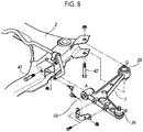
- FIG. 8 is a perspective view of a lower arm according to a prior art technology.
- a lower arm 1 As shown in FIG. 8 , a lower arm 1 according to a prior art technology is configured in a structure where a vehicular body mounting bush 10 (commonly referred to as an "A bush” in the art), a damping joint 20 (commonly referred to as a “G bush” in the art), and a ball joint 30 are coupled to three end portions.
- a vehicular body mounting bush 10 commonly referred to as an "A bush” in the art
- a damping joint 20 commonly referred to as a "G bush” in the art
- a ball joint 30 are coupled to three end portions.
- the vehicular body mounting bush 10 and the damping joint 20 are coupled to a vehicular body frame 2 through respective assembly bolts 41 and 42, and the ball joint 30 is coupled to a knuckle of the vehicular wheel to support the vehicular wheel together with an upper arm.
- the damping joint 20 simultaneously prevents, among random excitations transmitted from the outside of a vehicle, the following: an impact harshness phenomenon which is a temporary vibration generated after an impact sound when a tire of the vehicle passes over a protrusion of a road surface while the vehicle is being driven; a shimmy phenomenon in which the steering wheel of the vehicle that is turning shakes left and right in the turning direction; and a judder phenomenon in which noise or vibration is generated in the steering wheel or a dash panel when a braking force is applied while the vehicle is driven at a high speed.
- an impact harshness phenomenon which is a temporary vibration generated after an impact sound when a tire of the vehicle passes over a protrusion of a road surface while the vehicle is being driven
- a shimmy phenomenon in which the steering wheel of the vehicle that is turning shakes left and right in the turning direction
- a judder phenomenon in which noise or vibration is generated in the steering wheel or a dash panel when a braking force is applied while the vehicle is driven at a high speed
- FIG. 9 is a sectional view of a ball joint according to a prior art technology.
- the ball joint 30 includes a housing 31, a bearing 32, a cap 33, a ball stud 34, and a dust cover 35.
- the housing 31 is generally formed of a metal material for maintaining a strength of a ball bearing, and upper and lower ends of the housing are open.
- a deformed portion 38 is formed integrally at the lower end of the housing 31.
- the bearing 32 is mounted inside the housing 31 and is generally made of a plastic material. An upper end of the bearing 32 is open, and a space is formed in the bearing 32 such that a ball 39 of the ball stud 34 is inserted in the space.
- the cap 33 supports a lower portion of the bearing 32 and closes the lower end of the housing 31. That is, the bearing 32 is positioned inside the housing 31 and the lower end of the housing 31 is closed by the cap 33. At this time, the deformed portion 38 of the housing 31 protrudes below the cap 33. To assemble the cap 33 to the housing 31, the deformed portion 38 is caulked toward the cap 33.
- the ball 39 which is inserted into and pivoted in the space of the bearing 32, is formed at one end of the ball stud 34. Screw threads 37 are formed at the opposite end of the ball stud 34.
- the dust cover 35 prevents foreign matters from entering between the bearing 32 and the ball 39.
- the dust cover 35 is generally made of an elastic material such as rubber.
- the dust cover 35 is inserted to the ball stud 34 and is mounted to an upper portion of the housing 31. Further, the dust cover 35 includes fixing members 36 which fix upper and lower ends of the dust cover 35.
- the housing is made of a metal material by casting and had to be used by polishing the surfaces of the housing. Further, additional parts for assembling the ball joint must be used and thus the weight of the ball joint was increased. Accordingly, the weight of a vehicle in which several to dozens of ball joints are used is increased, thereby reducing the fuel efficiency of the vehicle.
- the prior art ball joint was required to undergo an additional assembly process of press-fitting the ball joint to the lower arm. Thus, there have been problems due to an increased manufacturing time and manufacturing costs.
- the present disclosure has been devised to solve the aforementioned problems, and the object of the present disclosure is to provide a hybrid arm in which a ball joint is integrally formed by insert-injection-molding a second body and a housing to a first body to which a reinforcement member is coupled, and a method of manufacturing such a hybrid arm.
- a hybrid arm may include: a first body made of a metal material and formed with a plurality of end portions; a second body formed so as to fill an inner side of the first body by being insert-injection-molded to the first body; and a ball joint formed integrally at a first end portion among the plurality of end portions of the first body.
- the ball joint may include: a reinforcement member coupled to the first end portion; a bearing member formed with a space therein; a ball stud including a ball rotatably inserted into the space of the bearing member and a rod extending upward of the ball; and a housing interposed between the reinforcement member and the bearing member and formed integrally with the second body.
- a through-hole portion may be formed in the reinforcement member to face the inner side of the first body to allow molten plastic to pass through.
- a concave portion may be formed in an inner circumferential surface of the reinforcement member along a circumferential direction.
- the bearing member may include a first bearing and a second bearing.
- a first protrusion portion the inner circumferential surface of which protrudes upward, may be formed in one of the first and second bearings.
- a second protrusion portion which corresponds to the first protrusion portion and the outer circumferential surface of which protrudes downward, may be formed in the other one of the first and second bearings.
- the housing may be formed by insert-injection-molding the reinforcement member and the bearing member with molten plastic, and the housing may support an outer circumferential surface of the bearing member and may surround an inner circumferential surface and an outer circumferential surface of the reinforcement member.
- An edge of the first body may extend downward to form first and second lateral reinforcement portions.
- a lower end of the first lateral reinforcement portion may extend toward the inner side of the first body to form a first extension portion.
- a lower end of the second lateral reinforcement portion may extend toward the inner side of the first body to form a second extension portion.
- the first and second extension portions may be formed in a shape that gradually increases in area toward the reinforcement member.
- a first circular arc portion corresponding to the outer circumferential surface of the reinforcement member may be formed at the first end portion of the first body.
- a first bonding portion may be formed at one side of the first lateral reinforcement portion so as to contact the outer circumferential surface of the reinforcement member.
- a second circular arc portion corresponding to the outer circumferential surface of the reinforcement member may be formed at one side of the first extension portion.
- a second bonding portion may be formed at one side of the second lateral reinforcement portion so as to contact the outer circumferential surface of the reinforcement member.
- a third circular arc portion corresponding to the outer circumferential surface of the reinforcement member may be formed at one side of the second extension portion.
- the reinforcement member may be welded to the first circular arc portion, the first bonding portion, the second circular arc portion, the second bonding portion, and the third circular arc portion.
- the second body may be formed so as to surround inward and outward surfaces of the first and second lateral reinforcement portions and inward and outward surfaces of the first and second extension portions.
- the second body may be made of a material different from the first body, and a plurality of reinforcement ribs extending downward may be provided in an inner side of the second body.
- a plurality of button holes may be formed in the first body.
- a plurality of button portions integrally coupled to the plurality of button holes may be formed.
- a method of manufacturing a hybrid arm may include: forming a first body by processing a metal plate material; coupling a reinforcement member to a first end portion of the first body; fixing a rod of a ball stud such that an outer circumferential surface of a bearing member is spaced apart from an inner circumferential surface of the reinforcement member; and insert-injection-molding a second body and a housing of a ball joint to the first body.
- a through-hole portion may be formed in the reinforcement member to allow molten plastic to pass through.
- Coupling the reinforcement member to the first end portion of the first body may include welding the reinforcement member to the first end portion of the first body such that the through-hole portion faces the inner side of the first body.
- Forming the first body by processing the metal plate material may include: forming first and second lateral reinforcement portions extending downward of the first body by processing an edge of the metal plate material; and forming first and second extension portions by processing lower ends of the first and second lateral reinforcement portions.
- the ball joint may be integrally formed in the hybrid arm by insert-injection-molding the second body and the housing to the first body to which the reinforcement member is coupled. Accordingly, the process of assembling the ball joint is eliminated, thereby improving productivity and reducing manufacturing costs. Further, since a separate cap component for the ball joint is not necessary, weight of the hybrid arm can be reduced.
- a hybrid arm and a method of manufacturing the same according to embodiments of the present disclosure described below are applicable to all arm members to which a ball joint for a vehicle is mounted.
- a lower arm for a vehicle is described as an embodiment.
- FIG. 1 is a front perspective view of a hybrid arm according to an embodiment of the present disclosure.
- FIG. 2 is a bottom perspective view of a first body according to an embodiment of the present disclosure.
- FIG. 3 shows part A of FIG. 2 .
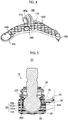
- FIG. 4 is a bottom perspective view of a hybrid arm according to an embodiment of the present disclosure.
- FIG. 5 is a sectional view showing part B of FIG. 1 .
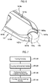
- FIG. 6 illustrates a coupling between a first body and a reinforcement member according to an embodiment of the present disclosure.
- FIG. 7 is a flowchart of a method of manufacturing a hybrid arm according to an embodiment of the present disclosure.
- FIG. 8 is a perspective view of a lower arm according to a prior art technology.
- FIG. 9 is a sectional view of a ball joint according to a prior art technology.
- a side of a hybrid arm 100 where the hybrid arm 100 is connected to a knuckle of a vehicular wheel is referred to as "one side” while a side of the hybrid arm 100 where the hybrid arm 100 is connected to a vehicular body frame when the hybrid arm 100 is installed on the vehicular body frame is referred to as the "opposite side.”
- a direction from the hybrid arm 100 toward the ground is referred to as “downward,” while a direction opposite thereto is referred to as “upward.”
- a direction in which a vehicle equipped with the hybrid arm 100 advances is referred to as “forward,” while a direction opposite thereto is referred to as "rearward.”
- the hybrid arm 100 may include a first body 141, a second body 143, and a ball joint 130 formed integrally at one end portion of the first body 141.
- the first body 141 is made of a metal material.
- the first body 141 is formed approximately in a shape of " ⁇ .”
- the first body 141 is formed approximately in a plate-like shape.
- the first body 141 is formed with three end portions. A first end portion is formed at one side of the first body 141, and second and third end portions are formed at the opposite sides of the first body. The second end portion is formed further forward than the third end portion.
- a ball joint 130 is formed integrally at the first end portion of the first body 141.
- the hybrid arm 100 may be connected to the knuckle of a vehicular wheel via the ball joint 130.
- a reinforcement member 135 is coupled to the first end portion of the first body 141.
- the reinforcement member 135 is formed in a cylindrical shape in which the upper and lower ends are both open.
- a first circular arc portion 141 a which corresponds to an outer circumferential surface of the reinforcement member 135, is formed at the first end portion of the first body 141.
- the first circular arc portion 141 a is recessed so as to be in contact with the outer circumferential surface of the reinforcement member 135.
- a center of the circular arc shape of the first circular arc portion 141 a may be located on a central axis of the reinforcement member 135.
- a bush hole 140a is formed at the second end portion of the first body 141.
- a mounting bush 110 may be inserted into the bush hole 140a so as to be connected to a vehicular body frame.
- a damping joint hole 140b is formed at the third end portion of the first body 141.
- a damping joint 120 may be inserted into the damping joint hole 140b so as to be connected to the vehicular body frame.
- a shock-absorber hole 1411 is formed to perforate the first body 141 in a vertical direction among the three end portions of the first body 141.
- a shock absorber may be inserted into and installed in the shock-absorber hole 1411.
- a plurality of first button holes 1413a are formed between the first end portion and the second end portion and are spaced apart from one another by a predetermined spacing.
- a plurality of first button portions 1435a are integrally coupled to the plurality of first button holes 1413a.
- the plurality of first button portions 1435a may be formed by injecting molten plastic into the plurality of first button holes 1413a.
- a plurality of second button holes 1413b may be formed between the second end portion and the third end portion.
- a plurality of second button portions 1435b are integrally coupled in the plurality of second button holes 1413b.
- the plurality of second button portions 1435b may be formed by injecting molten plastic into the plurality of second button holes 1413b.
- first body 141 extends downward to form first, second, and third lateral reinforcement portions 1415a, 1415b, and 1415c.
- the first, second, and third lateral reinforcement portions 1415a, 1415b, and 1415c may be integrally formed by bending the edge of the first body 141 downward.
- the first, second, and third lateral reinforcement portions 1415a, 1415b, and 1415c may constitute lateral surfaces of the first body 141.
- first body 141 a direction toward a portion surrounded by the first, second, and third lateral reinforcement portions 1415a, 1415b, and 1415c is referred to as “inward” of the first body 141, while a direction opposite thereto is referred to as “outward” of the first body 141.
- the first lateral reinforcement portion 1415a is formed between the first end portion and the second end portion of the first body 141.
- a first bonding portion 1417a is formed at one side of the first lateral reinforcement portion 1415a to be in contact with the outer circumferential surface of the reinforcement member 135.
- a lower end of the first lateral reinforcement portion 1415a extends inward of the first body 141 to form a first extension portion 1419a.
- the lower end of the first lateral reinforcement portion 1415a may be bent inward of the first body 141.
- a sectional shape of the first lateral reinforcement portion 1415a and the first extension portion 1419a may be formed in an "L" shape.
- a second circular arc portion 1421 a which corresponds to the outer circumferential surface of the reinforcement member 135, is formed at one side of the first extension portion 1419a.
- the second circular arc portion 1421 a is recessed so as to be in contact with the outer circumferential surface of the reinforcement member 135.
- a center of the circular arc shape of the second circular arc portion 1421 a may be located on the central axis of the reinforcement member 135.
- a radius of curvature of the second circular arc portion 1421 a may be the same as a radius of curvature of the first circular arc portion 141 a.
- the first and second circular arc portions 141 a and 1421 a are spaced apart from each other.
- the first extension portion 1419a may be formed in a shape that gradually increases in area toward the reinforcement member 135.
- the second lateral reinforcement portion 1415b is formed between the first end portion and the third end portion of the first body 141.
- a second bonding portion 1417b is formed at one side of the second lateral reinforcement portion 1415b to be in contact with the outer circumferential surface of the reinforcement member 135.
- a lower end of the second lateral reinforcement portion 1415b extends inward of the first body 141 to form a second extension portion 1419b.
- a third circular arc portion 1421b which corresponds to the outer circumferential surface of the reinforcement member 135, is formed at one side of the second extension portion 1419b.
- the third circular arc portion 1421 b is recessed so as to be in contact with the outer circumferential surface of the reinforcement member 135.
- a center of the circular arc shape of the third circular arc portion 1421b may be located on the central axis of the reinforcement member 135.
- a radius of curvature of the third circular arc portion 1421 b may be the same as the radius of curvature of the first circular arc portion 141 a.
- the first and third circular arc portions 141 a and 1421b are spaced apart from each other.
- the second extension portion 1419b may be formed in a shape that gradually increases in area toward the reinforcement member 135.
- the third lateral reinforcement portion 1415c is formed between the second end portion and the third end portion of the first body 141.
- a lower end of the third lateral reinforcement portion 1415c extends inward of the first body 141 to form a third extension portion 1419c.
- the second body 143 may be made of a plastic material.
- the second body 143 may be formed of Glass Fiber Reinforced Plastic (GFRP).
- GFRP Glass Fiber Reinforced Plastic
- the second body 143 may be formed approximately in the shape of " ⁇ " by being insert-injection-molded to the first body 141.
- a shock-absorber hole 1431 corresponding to the shock-absorber hole 1411 of the first body 141 is formed in the second body 143 to perforate the second body 143 in the vertical direction.
- the second body 143 is formed to fill the inside of the first body 141.
- the second body 143 may be formed so as to surround inward surfaces of the first, second, and third lateral reinforcement portions 1415a, 1415b, and 1415c and inward surfaces of the first, second, and third extension portions 1419a, 1419b and 1419c.
- the second body 143 may be formed so as to surround inward and outward surfaces of the first, second, and third lateral reinforcement portions 1415a, 1415b and 1415c and inward and outward surfaces of the first, second, and third extension portions 1419a, 1419b and 1419c.
- the first, second and third extension portions 1419a, 1419b, and 1419c extend inward of the first body 141.
- the first body 141 and the second body 143 can be firmly coupled to each other. That is, it is possible to prevent the second body 143 from being separated from the first body 141. Further, when an impact is applied from the front by a chipping phenomenon while the vehicle is being driven, the second body 143 may prevent the first lateral reinforcement portion 1415a of the first body 141 from being damaged.
- a plurality of reinforcement ribs 1433 extending downward may be provided in the inside of the second body 143.
- the plurality of reinforcement ribs 1433 may intersect each other and be configured in the form of a lattice. Both sides of the reinforcement ribs 1433 are coupled to the inward surfaces of the first, second, and third lateral reinforcement portions 1415a, 1415b and 1415c. For example, when one side of the reinforcement rib 1433 is coupled to the first lateral reinforcement portion 1415a, the opposite side is coupled to the second lateral reinforcement portion 1415b or the third lateral reinforcement portion 1415c.
- the plurality of reinforcement ribs 1433 support the first, second, and third lateral reinforcement portions 1415a, 1415b, and 1415c, thereby preventing the first body 141 from bending due to an external force.
- the second body 143 may be made of a material different from the first body 141.
- a volume ratio of the first body 141 may be in a range between 10% to 99%.
- the plurality of first button portions 1435a and the plurality of second button portions 1435b may be formed when the second body 143 is insert-injection-molded to the first body 141. Since the plurality of first button portions 1435a and the plurality of second button portions 1435b are integrally coupled to the plurality of first button holes 1413a and the plurality of second button holes 1413b, it is possible to prevent the second body 143 from being separated from or shaken with respect to the first body 141.
- the ball joint 130 may include the reinforcement member 135, a ball stud 137, a bearing member 131, and a housing 133.
- the reinforcement member 135 is formed in a cylindrical shape.
- the reinforcement member 135 may be made of a metal material.
- the reinforcement member 135 is coupled to the first end portion of the first body 141. Specifically, the reinforcement member 135 may be welded to the first circular arc portion 141 a, the first bonding portion 1417a, the second circular arc portion 1421 a, the second bonding portion 1417b, and the third circular arc portion 1421 b.
- a through-hole portion 1351 is formed in the reinforcement member 135 to face the inner side of the first body 141 such that molten plastic can pass through the through-hole portion. Molten plastic flows into a mold for the housing 133 through the through-hole portion 1351, and the housing 133 surrounding the reinforcement member 135 can be formed thereby.
- a concave portion 1353 may be formed in the inner circumferential surface of the reinforcement member 135.
- the concave portion 1353 may be formed along a circumferential direction in the inner circumferential surface of the lower end of the reinforcement member 135.
- a ball 1373 is formed at a lower end of the ball stud 137, and a rod 1371 having a circular pillar shape is formed integrally at an upper portion of the ball.
- the ball 1373 has a spherical shape, and the rod 1371 extends upward of the ball 1373.
- the bearing member 131 is formed in a cup shape having a space formed therein.
- the space has a shape of a sphere having a size similar to a size of the ball 1373.
- An upper end of the bearing member 131 is open, and a lower end thereof is closed.
- the ball 1373 of the ball stud 137 is rotatably inserted into the space of the bearing member 131.
- the bearing member 131 may be made of a lubricating plastic material.
- the bearing member 131 may include a first bearing 131 a and a second bearing 131b.
- the first bearing 131 a may be formed in a cup shape having an open upper end and a closed lower end.
- the second bearing 131b may be formed in an annular shape having upper and lower ends that are both open.
- a first protrusion portion 1311 a an inner circumferential surface of which protrudes upward, is formed at an upper end of the first bearing 131 a.
- a second protrusion portion 1311 b which corresponds to the first protrusion portion 1311 a and an outer circumferential surface of which protrudes downward, is formed at a lower end of the second bearing 131 b.
- the first protrusion portion 1311 a is brought into close contact with the second protrusion portion 1311b, thus preventing the molten plastic from infiltrating the inside of the bearing member 131. Further, since the first and second bearings 131 a and 131 b are coupled to each other to form the bearing member 131, the ball 1373 of the ball stud 137 does not need to be press-fitted into the inner space of the bearing member 131. Thus, it is possible to prevent the bearing member 131 from being damaged.
- the housing 133 is formed integrally with the second body 143.
- the housing may be interposed between the reinforcement member 135 and the bearing member 131 to support an outer circumferential surface of the bearing member 131.
- the housing 133 may be formed by insert-injection-molding the reinforcement member 135 and the bearing member 131 with molten plastic. That is, the housing 133 may be formed simultaneously with the second body 143.
- the housing 133 may be provided so as to surround both inner and outer circumferential surfaces of the reinforcement member 135.
- a dust cover 139 may be mounted to an upper end of the housing 133 in order to prevent foreign matters such as dust or water from infiltrating between the bearing member 131 and the ball 1373.
- the dust cover 139 may be made of a rubber material.
- the dust cover 139 may be fixed to the upper end of the housing 133 by a fixing member 132.
- the first body 141 is formed by processing a metal plate material, which is the material of the first body 141 (ST 110).
- the first, second, and third lateral reinforcement portions 415a, 1415b, and 1415c are formed by press working edges of the metal plate material.
- the first, second, and third extension portions 1415a, 1415b, and 1415c are formed by processing the lower ends of the first, second, and third lateral reinforcement portions 415a, 1415b, and 1415c.
- the shock-absorber hole 1411, the plurality of first button holes 1413a, and the plurality of second button holes 1413b are formed.
- the reinforcement member 135 is coupled to the first end portion of the first body 141 (ST 120). Specifically, the reinforcement member 135 may be welded to the first circular arc portion 141 a, the first bonding portion 1417a, the second circular arc portion 1421 a, the second bonding portion 1417b, and the third circular arc portion 1421b. At this time, the reinforcement member 135 may be coupled to the first body 141 such that the through-hole portion 1351 of the reinforcement member 135 faces the inner side of the first body 141.
- the first body 141 When the reinforcement member 135 is coupled to the first body 141, the first body 141 is positioned in a pre-made injection-molding mold (ST 130).
- the bearing member 131, to which the ball stud 137 is coupled, is inserted into the reinforcement member 135.
- the rod 1371 of the ball stud 137 is fixed such that the outer circumferential surface of the bearing member 131 is spaced apart from the inner circumferential surface of the reinforcement member 135. Accordingly, a space, into which molten plastic can flow, may be formed between the outer circumferential surface of the bearing member 131 and the inner circumferential surface of the reinforcement member 135.
- the second body 143 and the housing 133 of the ball joint 130 are insert-injection-molded to the first body 141 (ST 140). Since the molten plastic surrounds the inward and outward surfaces of the first, second, and third lateral reinforcement portions 1415a, 1415b, and 1415c of the second body 143 and the inward and outward surfaces of the first, second, and third extension portions 1419a, 1419b, and 1419c, and is then solidified, the first body 141 and the second body 143 can be firmly coupled to each other. At this time, the plurality of reinforcement ribs 1433 may be formed inside the second body 143.
- the molten plastic flows to the plurality of first button holes 1413a and the plurality of second button holes 1413b to form the plurality of first button portions 1435a and the plurality of second button portions 1435b. Accordingly, it is possible to prevent the second body 143 from being separated from the first body 141 or from being shaken with respect to the first body 141.
- the molten plastic filling the inside of the first body 141 flows into the space formed between the outer circumferential surface of the bearing member 131 and the inner circumferential surface of the reinforcement member 135 through the through-hole portion 1351 and is then solidified.
- the ball joint 130 may be formed integrally with the hybrid arm 100.
- the second body 143 and the housing 133 are insert-injection-molded to the first body 141 to which the reinforcement member 135 is coupled.
- the ball joint 130 may be formed integrally with the hybrid arm 100. Accordingly, the process of assembling the ball joint 130 is eliminated, thereby improving productivity and reducing manufacturing costs. Further, since a separate cap component for the ball joint 130 is not necessary, the weight of the hybrid arm 100 can be reduced.
Landscapes
- Engineering & Computer Science (AREA)
- Mechanical Engineering (AREA)
- General Engineering & Computer Science (AREA)
- Manufacturing & Machinery (AREA)
- Vehicle Body Suspensions (AREA)
- Pivots And Pivotal Connections (AREA)
- Injection Moulding Of Plastics Or The Like (AREA)
Abstract
Description
- The present disclosure relates to a hybrid arm and a method of manufacturing the same. More particularly, the present disclosure relates to a hybrid arm in which a ball joint is integrally formed, and a method of manufacturing the hybrid arm.
- Generally, a vehicular suspension system is an apparatus for connecting a wheel to a vehicular body. The suspension system consists of a spring that absorbs impact from a road surface, a shock absorber that adjusts an action of the spring, an arm or link that controls an operation of the wheel, and a stabilizer that prevents rolling of a vehicle.
- The aforementioned vehicular suspension system is an important apparatus for promoting ride comfort and driving stability, and mainly performs the functions of suppressing or rapidly reducing vibrations transmitted from a vehicular wheel while stably supporting the vehicular body from the vehicular wheel in a stable manner.
- In such a suspension system, a lower arm is used to perform the functions of connecting the vehicular wheel to the vehicular body and supporting the vehicular wheel.
-
FIG. 8 is a perspective view of a lower arm according to a prior art technology. - As shown in
FIG. 8 , alower arm 1 according to a prior art technology is configured in a structure where a vehicular body mounting bush 10 (commonly referred to as an "A bush" in the art), a damping joint 20 (commonly referred to as a "G bush" in the art), and aball joint 30 are coupled to three end portions. - In this regard, the vehicular
body mounting bush 10 and the dampingjoint 20 are coupled to a vehicular body frame 2 throughrespective assembly bolts ball joint 30 is coupled to a knuckle of the vehicular wheel to support the vehicular wheel together with an upper arm. - The damping
joint 20 simultaneously prevents, among random excitations transmitted from the outside of a vehicle, the following: an impact harshness phenomenon which is a temporary vibration generated after an impact sound when a tire of the vehicle passes over a protrusion of a road surface while the vehicle is being driven; a shimmy phenomenon in which the steering wheel of the vehicle that is turning shakes left and right in the turning direction; and a judder phenomenon in which noise or vibration is generated in the steering wheel or a dash panel when a braking force is applied while the vehicle is driven at a high speed. -
FIG. 9 is a sectional view of a ball joint according to a prior art technology. - As shown in
FIG. 9 , theball joint 30 according to prior art includes ahousing 31, abearing 32, acap 33, aball stud 34, and adust cover 35. - The
housing 31 is generally formed of a metal material for maintaining a strength of a ball bearing, and upper and lower ends of the housing are open. Adeformed portion 38 is formed integrally at the lower end of thehousing 31. - The
bearing 32 is mounted inside thehousing 31 and is generally made of a plastic material. An upper end of thebearing 32 is open, and a space is formed in thebearing 32 such that aball 39 of theball stud 34 is inserted in the space. - The
cap 33 supports a lower portion of thebearing 32 and closes the lower end of thehousing 31. That is, thebearing 32 is positioned inside thehousing 31 and the lower end of thehousing 31 is closed by thecap 33. At this time, thedeformed portion 38 of thehousing 31 protrudes below thecap 33. To assemble thecap 33 to thehousing 31, thedeformed portion 38 is caulked toward thecap 33. - The
ball 39, which is inserted into and pivoted in the space of thebearing 32, is formed at one end of theball stud 34.Screw threads 37 are formed at the opposite end of theball stud 34. - The
dust cover 35 prevents foreign matters from entering between thebearing 32 and theball 39. Thedust cover 35 is generally made of an elastic material such as rubber. Thedust cover 35 is inserted to theball stud 34 and is mounted to an upper portion of thehousing 31. Further, thedust cover 35 includesfixing members 36 which fix upper and lower ends of thedust cover 35. - However, in the above-described ball joint of the prior art, the housing is made of a metal material by casting and had to be used by polishing the surfaces of the housing. Further, additional parts for assembling the ball joint must be used and thus the weight of the ball joint was increased. Accordingly, the weight of a vehicle in which several to dozens of ball joints are used is increased, thereby reducing the fuel efficiency of the vehicle. In addition, the prior art ball joint was required to undergo an additional assembly process of press-fitting the ball joint to the lower arm. Thus, there have been problems due to an increased manufacturing time and manufacturing costs.
- Therefore, the present disclosure has been devised to solve the aforementioned problems, and the object of the present disclosure is to provide a hybrid arm in which a ball joint is integrally formed by insert-injection-molding a second body and a housing to a first body to which a reinforcement member is coupled, and a method of manufacturing such a hybrid arm.
- A hybrid arm according to an embodiment of the present disclosure may include: a first body made of a metal material and formed with a plurality of end portions; a second body formed so as to fill an inner side of the first body by being insert-injection-molded to the first body; and a ball joint formed integrally at a first end portion among the plurality of end portions of the first body. The ball joint may include: a reinforcement member coupled to the first end portion; a bearing member formed with a space therein; a ball stud including a ball rotatably inserted into the space of the bearing member and a rod extending upward of the ball; and a housing interposed between the reinforcement member and the bearing member and formed integrally with the second body.
- A through-hole portion may be formed in the reinforcement member to face the inner side of the first body to allow molten plastic to pass through.
- A concave portion may be formed in an inner circumferential surface of the reinforcement member along a circumferential direction.
- The bearing member may include a first bearing and a second bearing. A first protrusion portion, the inner circumferential surface of which protrudes upward, may be formed in one of the first and second bearings. A second protrusion portion, which corresponds to the first protrusion portion and the outer circumferential surface of which protrudes downward, may be formed in the other one of the first and second bearings.
- The housing may be formed by insert-injection-molding the reinforcement member and the bearing member with molten plastic, and the housing may support an outer circumferential surface of the bearing member and may surround an inner circumferential surface and an outer circumferential surface of the reinforcement member.
- An edge of the first body may extend downward to form first and second lateral reinforcement portions. A lower end of the first lateral reinforcement portion may extend toward the inner side of the first body to form a first extension portion. A lower end of the second lateral reinforcement portion may extend toward the inner side of the first body to form a second extension portion. The first and second extension portions may be formed in a shape that gradually increases in area toward the reinforcement member.
- A first circular arc portion corresponding to the outer circumferential surface of the reinforcement member may be formed at the first end portion of the first body. A first bonding portion may be formed at one side of the first lateral reinforcement portion so as to contact the outer circumferential surface of the reinforcement member. A second circular arc portion corresponding to the outer circumferential surface of the reinforcement member may be formed at one side of the first extension portion. A second bonding portion may be formed at one side of the second lateral reinforcement portion so as to contact the outer circumferential surface of the reinforcement member. A third circular arc portion corresponding to the outer circumferential surface of the reinforcement member may be formed at one side of the second extension portion.
- The reinforcement member may be welded to the first circular arc portion, the first bonding portion, the second circular arc portion, the second bonding portion, and the third circular arc portion.
- The second body may be formed so as to surround inward and outward surfaces of the first and second lateral reinforcement portions and inward and outward surfaces of the first and second extension portions.
- The second body may be made of a material different from the first body, and a plurality of reinforcement ribs extending downward may be provided in an inner side of the second body.
- A plurality of button holes may be formed in the first body. When the second body is insert-injection-molded to the first body, a plurality of button portions integrally coupled to the plurality of button holes may be formed.
- A method of manufacturing a hybrid arm according to an embodiment of the present disclosure may include: forming a first body by processing a metal plate material; coupling a reinforcement member to a first end portion of the first body; fixing a rod of a ball stud such that an outer circumferential surface of a bearing member is spaced apart from an inner circumferential surface of the reinforcement member; and insert-injection-molding a second body and a housing of a ball joint to the first body.
- A through-hole portion may be formed in the reinforcement member to allow molten plastic to pass through. Coupling the reinforcement member to the first end portion of the first body may include welding the reinforcement member to the first end portion of the first body such that the through-hole portion faces the inner side of the first body.
- Forming the first body by processing the metal plate material may include: forming first and second lateral reinforcement portions extending downward of the first body by processing an edge of the metal plate material; and forming first and second extension portions by processing lower ends of the first and second lateral reinforcement portions.
- According to the above-described embodiments of the present disclosure, the ball joint may be integrally formed in the hybrid arm by insert-injection-molding the second body and the housing to the first body to which the reinforcement member is coupled. Accordingly, the process of assembling the ball joint is eliminated, thereby improving productivity and reducing manufacturing costs. Further, since a separate cap component for the ball joint is not necessary, weight of the hybrid arm can be reduced.
-
-
FIG. 1 is a front perspective view of a hybrid arm according to an embodiment of the present disclosure. -
FIG. 2 is a bottom perspective view of a first body according to an embodiment of the present disclosure. -
FIG. 3 shows part A ofFIG. 2 . -
FIG. 4 is a bottom perspective view of a hybrid arm according to an embodiment of the present disclosure. -
FIG. 5 is a sectional view showing part B ofFIG. 1 . -
FIG. 6 illustrates a coupling between a first body and a reinforcement member according to an embodiment of the present disclosure. -
FIG. 7 is a flowchart of a method of manufacturing a hybrid arm according to an embodiment of the present disclosure. -
FIG. 8 is a perspective view of a lower arm according to a prior art technology. -
FIG. 9 is a sectional view of a ball joint according to a prior art technology. - Hereinafter, detailed descriptions are made as to embodiments of the present disclosure with reference to the accompanying drawings such that those of ordinary skill in the technical field to which the present disclosure pertains can easily carry out the embodiments. However, the present disclosure is not limited to the embodiments described herein, but may be embodied in other forms.
- A hybrid arm and a method of manufacturing the same according to embodiments of the present disclosure described below are applicable to all arm members to which a ball joint for a vehicle is mounted. In the descriptions below, a lower arm for a vehicle is described as an embodiment.
-
FIG. 1 is a front perspective view of a hybrid arm according to an embodiment of the present disclosure.FIG. 2 is a bottom perspective view of a first body according to an embodiment of the present disclosure.FIG. 3 shows part A ofFIG. 2 .FIG. 4 is a bottom perspective view of a hybrid arm according to an embodiment of the present disclosure.FIG. 5 is a sectional view showing part B ofFIG. 1 .FIG. 6 illustrates a coupling between a first body and a reinforcement member according to an embodiment of the present disclosure.FIG. 7 is a flowchart of a method of manufacturing a hybrid arm according to an embodiment of the present disclosure.FIG. 8 is a perspective view of a lower arm according to a prior art technology.FIG. 9 is a sectional view of a ball joint according to a prior art technology. - In the descriptions below, for ease of description, with respect to
FIG. 1 as a reference, a side of ahybrid arm 100 where thehybrid arm 100 is connected to a knuckle of a vehicular wheel is referred to as "one side," while a side of thehybrid arm 100 where thehybrid arm 100 is connected to a vehicular body frame when thehybrid arm 100 is installed on the vehicular body frame is referred to as the "opposite side." A direction from thehybrid arm 100 toward the ground is referred to as "downward," while a direction opposite thereto is referred to as "upward." A direction in which a vehicle equipped with thehybrid arm 100 advances is referred to as "forward," while a direction opposite thereto is referred to as "rearward." - Hereinafter, the
hybrid arm 100 according to an embodiment of the present disclosure is described in detail with reference toFIGS. 1 to 6 . - As shown in
FIGS. 1 to 6 , thehybrid arm 100 according to an embodiment of the present disclosure may include afirst body 141, asecond body 143, and a ball joint 130 formed integrally at one end portion of thefirst body 141. - The
first body 141 is made of a metal material. Thefirst body 141 is formed approximately in a shape of "λ." Thefirst body 141 is formed approximately in a plate-like shape. - The
first body 141 is formed with three end portions. A first end portion is formed at one side of thefirst body 141, and second and third end portions are formed at the opposite sides of the first body. The second end portion is formed further forward than the third end portion. - A ball joint 130 is formed integrally at the first end portion of the
first body 141. Thehybrid arm 100 may be connected to the knuckle of a vehicular wheel via the ball joint 130. To form thefirst body 141 and the ball joint 130 integrally together, areinforcement member 135 is coupled to the first end portion of thefirst body 141. Thereinforcement member 135 is formed in a cylindrical shape in which the upper and lower ends are both open. A firstcircular arc portion 141 a, which corresponds to an outer circumferential surface of thereinforcement member 135, is formed at the first end portion of thefirst body 141. The firstcircular arc portion 141 a is recessed so as to be in contact with the outer circumferential surface of thereinforcement member 135. A center of the circular arc shape of the firstcircular arc portion 141 a may be located on a central axis of thereinforcement member 135. - A
bush hole 140a is formed at the second end portion of thefirst body 141. A mountingbush 110 may be inserted into thebush hole 140a so as to be connected to a vehicular body frame. - A damping
joint hole 140b is formed at the third end portion of thefirst body 141. A damping joint 120 may be inserted into the dampingjoint hole 140b so as to be connected to the vehicular body frame. - A shock-
absorber hole 1411 is formed to perforate thefirst body 141 in a vertical direction among the three end portions of thefirst body 141. A shock absorber may be inserted into and installed in the shock-absorber hole 1411. - A plurality of
first button holes 1413a are formed between the first end portion and the second end portion and are spaced apart from one another by a predetermined spacing. A plurality offirst button portions 1435a are integrally coupled to the plurality offirst button holes 1413a. The plurality offirst button portions 1435a may be formed by injecting molten plastic into the plurality offirst button holes 1413a. - A plurality of
second button holes 1413b may be formed between the second end portion and the third end portion. A plurality ofsecond button portions 1435b are integrally coupled in the plurality ofsecond button holes 1413b. The plurality ofsecond button portions 1435b may be formed by injecting molten plastic into the plurality ofsecond button holes 1413b. - An edge of the
first body 141 extends downward to form first, second, and thirdlateral reinforcement portions lateral reinforcement portions first body 141 downward. The first, second, and thirdlateral reinforcement portions first body 141. - Hereinafter, a direction toward a portion surrounded by the first, second, and third
lateral reinforcement portions first body 141, while a direction opposite thereto is referred to as "outward" of thefirst body 141. - The first
lateral reinforcement portion 1415a is formed between the first end portion and the second end portion of thefirst body 141. Afirst bonding portion 1417a is formed at one side of the firstlateral reinforcement portion 1415a to be in contact with the outer circumferential surface of thereinforcement member 135. - A lower end of the first
lateral reinforcement portion 1415a extends inward of thefirst body 141 to form afirst extension portion 1419a. The lower end of the firstlateral reinforcement portion 1415a may be bent inward of thefirst body 141. A sectional shape of the firstlateral reinforcement portion 1415a and thefirst extension portion 1419a may be formed in an "L" shape. A secondcircular arc portion 1421 a, which corresponds to the outer circumferential surface of thereinforcement member 135, is formed at one side of thefirst extension portion 1419a. The secondcircular arc portion 1421 a is recessed so as to be in contact with the outer circumferential surface of thereinforcement member 135. A center of the circular arc shape of the secondcircular arc portion 1421 a may be located on the central axis of thereinforcement member 135. A radius of curvature of the secondcircular arc portion 1421 a may be the same as a radius of curvature of the firstcircular arc portion 141 a. The first and secondcircular arc portions first extension portion 1419a may be formed in a shape that gradually increases in area toward thereinforcement member 135. - The second
lateral reinforcement portion 1415b is formed between the first end portion and the third end portion of thefirst body 141. Asecond bonding portion 1417b is formed at one side of the secondlateral reinforcement portion 1415b to be in contact with the outer circumferential surface of thereinforcement member 135. - A lower end of the second
lateral reinforcement portion 1415b extends inward of thefirst body 141 to form asecond extension portion 1419b. A thirdcircular arc portion 1421b, which corresponds to the outer circumferential surface of thereinforcement member 135, is formed at one side of thesecond extension portion 1419b. The thirdcircular arc portion 1421 b is recessed so as to be in contact with the outer circumferential surface of thereinforcement member 135. A center of the circular arc shape of the thirdcircular arc portion 1421b may be located on the central axis of thereinforcement member 135. A radius of curvature of the thirdcircular arc portion 1421 b may be the same as the radius of curvature of the firstcircular arc portion 141 a. The first and thirdcircular arc portions second extension portion 1419b may be formed in a shape that gradually increases in area toward thereinforcement member 135. - The third
lateral reinforcement portion 1415c is formed between the second end portion and the third end portion of thefirst body 141. A lower end of the thirdlateral reinforcement portion 1415c extends inward of thefirst body 141 to form a third extension portion 1419c. - The
second body 143 may be made of a plastic material. For example, thesecond body 143 may be formed of Glass Fiber Reinforced Plastic (GFRP). Thesecond body 143 may be formed approximately in the shape of "λ" by being insert-injection-molded to thefirst body 141. - A shock-
absorber hole 1431 corresponding to the shock-absorber hole 1411 of thefirst body 141 is formed in thesecond body 143 to perforate thesecond body 143 in the vertical direction. - The
second body 143 is formed to fill the inside of thefirst body 141. Thesecond body 143 may be formed so as to surround inward surfaces of the first, second, and thirdlateral reinforcement portions third extension portions second body 143 may be formed so as to surround inward and outward surfaces of the first, second, and thirdlateral reinforcement portions third extension portions third extension portions first body 141. Thus, in the case where thesecond body 143 is formed so as to surround the inward and outward surfaces of the first, second, and thirdlateral reinforcement portions third extension portions first body 141 and thesecond body 143 can be firmly coupled to each other. That is, it is possible to prevent thesecond body 143 from being separated from thefirst body 141. Further, when an impact is applied from the front by a chipping phenomenon while the vehicle is being driven, thesecond body 143 may prevent the firstlateral reinforcement portion 1415a of thefirst body 141 from being damaged. - A plurality of
reinforcement ribs 1433 extending downward may be provided in the inside of thesecond body 143. The plurality ofreinforcement ribs 1433 may intersect each other and be configured in the form of a lattice. Both sides of thereinforcement ribs 1433 are coupled to the inward surfaces of the first, second, and thirdlateral reinforcement portions reinforcement rib 1433 is coupled to the firstlateral reinforcement portion 1415a, the opposite side is coupled to the secondlateral reinforcement portion 1415b or the thirdlateral reinforcement portion 1415c. The plurality ofreinforcement ribs 1433 support the first, second, and thirdlateral reinforcement portions first body 141 from bending due to an external force. - The
second body 143 may be made of a material different from thefirst body 141. When thesecond body 143 is made of a material different from thefirst body 141, a volume ratio of thefirst body 141 may be in a range between 10% to 99%. - The plurality of
first button portions 1435a and the plurality ofsecond button portions 1435b may be formed when thesecond body 143 is insert-injection-molded to thefirst body 141. Since the plurality offirst button portions 1435a and the plurality ofsecond button portions 1435b are integrally coupled to the plurality offirst button holes 1413a and the plurality ofsecond button holes 1413b, it is possible to prevent thesecond body 143 from being separated from or shaken with respect to thefirst body 141. - As shown in
FIG. 5 , the ball joint 130 may include thereinforcement member 135, aball stud 137, a bearingmember 131, and ahousing 133. - The
reinforcement member 135 is formed in a cylindrical shape. Thereinforcement member 135 may be made of a metal material. Thereinforcement member 135 is coupled to the first end portion of thefirst body 141. Specifically, thereinforcement member 135 may be welded to the firstcircular arc portion 141 a, thefirst bonding portion 1417a, the secondcircular arc portion 1421 a, thesecond bonding portion 1417b, and the thirdcircular arc portion 1421 b. - A through-
hole portion 1351 is formed in thereinforcement member 135 to face the inner side of thefirst body 141 such that molten plastic can pass through the through-hole portion. Molten plastic flows into a mold for thehousing 133 through the through-hole portion 1351, and thehousing 133 surrounding thereinforcement member 135 can be formed thereby. - A
concave portion 1353 may be formed in the inner circumferential surface of thereinforcement member 135. For example, theconcave portion 1353 may be formed along a circumferential direction in the inner circumferential surface of the lower end of thereinforcement member 135. When thehousing 133 is insert-injection-molded, molten plastic may be inserted into and solidified in theconcave portion 1353, thus increasing the coupling force between thereinforcement member 135 and thehousing 133. - A
ball 1373 is formed at a lower end of theball stud 137, and a rod 1371 having a circular pillar shape is formed integrally at an upper portion of the ball. Theball 1373 has a spherical shape, and the rod 1371 extends upward of theball 1373. - The bearing
member 131 is formed in a cup shape having a space formed therein. The space has a shape of a sphere having a size similar to a size of theball 1373. An upper end of the bearingmember 131 is open, and a lower end thereof is closed. Theball 1373 of theball stud 137 is rotatably inserted into the space of the bearingmember 131. The bearingmember 131 may be made of a lubricating plastic material. - The bearing
member 131 may include afirst bearing 131 a and asecond bearing 131b. Thefirst bearing 131 a may be formed in a cup shape having an open upper end and a closed lower end. Thesecond bearing 131b may be formed in an annular shape having upper and lower ends that are both open. - A
first protrusion portion 1311 a, an inner circumferential surface of which protrudes upward, is formed at an upper end of thefirst bearing 131 a. Asecond protrusion portion 1311 b, which corresponds to thefirst protrusion portion 1311 a and an outer circumferential surface of which protrudes downward, is formed at a lower end of thesecond bearing 131 b. - When the first and
second bearings first protrusion portion 1311 a is brought into close contact with thesecond protrusion portion 1311b, thus preventing the molten plastic from infiltrating the inside of the bearingmember 131. Further, since the first andsecond bearings member 131, theball 1373 of theball stud 137 does not need to be press-fitted into the inner space of the bearingmember 131. Thus, it is possible to prevent the bearingmember 131 from being damaged. - The
housing 133 is formed integrally with thesecond body 143. The housing may be interposed between thereinforcement member 135 and the bearingmember 131 to support an outer circumferential surface of the bearingmember 131. Thehousing 133 may be formed by insert-injection-molding thereinforcement member 135 and the bearingmember 131 with molten plastic. That is, thehousing 133 may be formed simultaneously with thesecond body 143. Thehousing 133 may be provided so as to surround both inner and outer circumferential surfaces of thereinforcement member 135. - A
dust cover 139 may be mounted to an upper end of thehousing 133 in order to prevent foreign matters such as dust or water from infiltrating between the bearingmember 131 and theball 1373. Thedust cover 139 may be made of a rubber material. Thedust cover 139 may be fixed to the upper end of thehousing 133 by a fixingmember 132. - Hereinafter, a method of manufacturing a hybrid arm according to an embodiment of the present disclosure is described with reference to
FIG. 7 . - The
first body 141 is formed by processing a metal plate material, which is the material of the first body 141 (ST 110). The first, second, and thirdlateral reinforcement portions lateral reinforcement portions third extension portions lateral reinforcement portions absorber hole 1411, the plurality offirst button holes 1413a, and the plurality ofsecond button holes 1413b are formed. - When the
first body 141 is formed, thereinforcement member 135 is coupled to the first end portion of the first body 141 (ST 120). Specifically, thereinforcement member 135 may be welded to the firstcircular arc portion 141 a, thefirst bonding portion 1417a, the secondcircular arc portion 1421 a, thesecond bonding portion 1417b, and the thirdcircular arc portion 1421b. At this time, thereinforcement member 135 may be coupled to thefirst body 141 such that the through-hole portion 1351 of thereinforcement member 135 faces the inner side of thefirst body 141. - When the
reinforcement member 135 is coupled to thefirst body 141, thefirst body 141 is positioned in a pre-made injection-molding mold (ST 130). The bearingmember 131, to which theball stud 137 is coupled, is inserted into thereinforcement member 135. The rod 1371 of theball stud 137 is fixed such that the outer circumferential surface of the bearingmember 131 is spaced apart from the inner circumferential surface of thereinforcement member 135. Accordingly, a space, into which molten plastic can flow, may be formed between the outer circumferential surface of the bearingmember 131 and the inner circumferential surface of thereinforcement member 135. - Thereafter, molten plastic is injected into the injection-molding mold, and the
second body 143 and thehousing 133 of the ball joint 130 are insert-injection-molded to the first body 141 (ST 140). Since the molten plastic surrounds the inward and outward surfaces of the first, second, and thirdlateral reinforcement portions second body 143 and the inward and outward surfaces of the first, second, andthird extension portions first body 141 and thesecond body 143 can be firmly coupled to each other. At this time, the plurality ofreinforcement ribs 1433 may be formed inside thesecond body 143. Further, the molten plastic flows to the plurality offirst button holes 1413a and the plurality ofsecond button holes 1413b to form the plurality offirst button portions 1435a and the plurality ofsecond button portions 1435b. Accordingly, it is possible to prevent thesecond body 143 from being separated from thefirst body 141 or from being shaken with respect to thefirst body 141. - The molten plastic filling the inside of the
first body 141 flows into the space formed between the outer circumferential surface of the bearingmember 131 and the inner circumferential surface of thereinforcement member 135 through the through-hole portion 1351 and is then solidified. Thus, the ball joint 130 may be formed integrally with thehybrid arm 100. - As described above, according to an embodiment of the present disclosure, the
second body 143 and thehousing 133 are insert-injection-molded to thefirst body 141 to which thereinforcement member 135 is coupled. Thus, the ball joint 130 may be formed integrally with thehybrid arm 100. Accordingly, the process of assembling the ball joint 130 is eliminated, thereby improving productivity and reducing manufacturing costs. Further, since a separate cap component for the ball joint 130 is not necessary, the weight of thehybrid arm 100 can be reduced. - While the embodiments of the present disclosure has been described in detail hereinbefore, the present disclosure is not limited thereto. Various modifications and improvements, which may be made by those of ordinarily skill in the art using the basic concept of the present disclosure defined in the appended claims, are intended to fall within the protection scope of the present disclosure.
Claims (14)
- A hybrid arm comprising:a first body made of a metal material and formed with a plurality of end portions;a second body formed so as to fill an inner side of the first body by being insert-injection-molded to the first body; anda ball joint formed integrally at a first end portion among the plurality of end portions of the first body,wherein the ball joint comprises:a reinforcement member coupled to the first end portion;a bearing member formed with a space therein;a ball stud including a ball rotatably inserted into the space of the bearing member and a rod extending upward of the ball; anda housing interposed between the reinforcement member and the bearing member and formed integrally with the second body.
- The hybrid arm of Claim 1, wherein a through-hole portion is formed in the reinforcement member to face the inner side of the first body to allow molten plastic to pass through.
- The hybrid arm of Claim 1, wherein a concave portion is formed in an inner circumferential surface of the reinforcement member along a circumferential direction.
- The hybrid arm of Claim 1, wherein the bearing member includes a first bearing and a second bearing,
wherein a first protrusion portion, an inner circumferential surface of which protrudes upward, is formed in one of the first and second bearings, and
wherein a second protrusion portion, which corresponds to the first protrusion portion and an outer circumferential surface of which protrudes downward, is formed in the other one of the first and second bearings. - The hybrid arm of Claim 1, wherein the housing is formed by insert-injection-molding the reinforcement member and the bearing member with molten plastic, and the housing supports an outer circumferential surface of the bearing member and surrounds an inner circumferential surface and an outer circumferential surface of the reinforcement member.
- The hybrid arm of Claim 1, wherein an edge of the first body extends downward to form first and second lateral reinforcement portions,
wherein a lower end of the first lateral reinforcement portion extends toward the inner side of the first body to form a first extension portion,
wherein a lower end of the second lateral reinforcement portion extends toward the inner side of the first body to form a second extension portion, and
wherein the first and second extension portions are formed in a shape that gradually increases in area toward the reinforcement member. - The hybrid arm of Claim 6, wherein a first circular arc portion corresponding to an outer circumferential surface of the reinforcement member is formed at the first end portion of the first body,
wherein a first bonding portion is formed at one side of the first lateral reinforcement portion so as to contact the outer circumferential surface of the reinforcement member,
wherein a second circular arc portion corresponding to the outer circumferential surface of the reinforcement member is formed at one side of the first extension portion,
wherein a second bonding portion is formed at one side of the second lateral reinforcement portion so as to contact the outer circumferential surface of the reinforcement member, and
wherein a third circular arc portion corresponding to the outer circumferential surface of the reinforcement member is formed at one side of the second extension portion. - The hybrid arm of Claim 7, wherein the reinforcement member is welded to the first circular arc portion, the first bonding portion, the second circular arc portion, the second bonding portion, and the third circular arc portion.
- The hybrid arm of Claim 7, wherein the second body is formed so as to surround inward and outward surfaces of the first and second lateral reinforcement portions and inward and outward surfaces of the first and second extension portions.
- The hybrid arm of Claim 9, wherein the second body is formed of a material different from the first body, and a plurality of reinforcement ribs extending downward are provided in an inner side of the second body.
- The hybrid arm of Claim 1, wherein a plurality of button holes are formed in the first body, and
wherein when the second body is insert-injection-molded with the first body, a plurality of button portions integrally coupled to the plurality of button holes are formed. - A method of manufacturing a hybrid arm which includes a first body made of a metal material and formed with a plurality of end portions, a second body formed to fill an inner side of the first body, and a ball joint formed integrally at a first end portion among the plurality of end portions of the first body, the method comprising:forming the first body by processing a metal plate material;coupling a reinforcement member to the first end portion of the first body;fixing a rod of a ball stud such that an outer circumferential surface of a bearing member is spaced apart from an inner circumferential surface of the reinforcement member; andinsert-injection-molding the second body and a housing of the ball joint to the first body.
- The method of Claim 12, wherein a through-hole portion is formed in the reinforcement member to allow molten plastic to pass through, and
wherein coupling the reinforcement member to the first end portion of the first body comprises welding the reinforcement member to the first end portion of the first body such that the through-hole portion faces the inner side of the first body. - The method of Claim 12, wherein forming the first body by processing the metal plate material comprises:forming first and second lateral reinforcement portions extending downward of the first body by processing an edge of the metal plate material; andforming first and second extension portions by processing lower ends of the first and second lateral reinforcement portions.
Applications Claiming Priority (2)
| Application Number | Priority Date | Filing Date | Title |
|---|---|---|---|
| KR1020150060779A KR101732063B1 (en) | 2015-04-29 | 2015-04-29 | Hybrid Arm With Ball Joint Integrated For Vehicle And The Method Thereof |
| PCT/KR2015/012629 WO2016175417A1 (en) | 2015-04-29 | 2015-11-24 | Hybrid arm and method for manufacturing same |
Publications (2)
| Publication Number | Publication Date |
|---|---|
| EP3290242A1 true EP3290242A1 (en) | 2018-03-07 |
| EP3290242A4 EP3290242A4 (en) | 2018-12-19 |
Family
ID=57198666
Family Applications (1)
| Application Number | Title | Priority Date | Filing Date |
|---|---|---|---|
| EP15890858.2A Withdrawn EP3290242A4 (en) | 2015-04-29 | 2015-11-24 | Hybrid arm and method for manufacturing same |
Country Status (6)
| Country | Link |
|---|---|
| US (1) | US10442262B2 (en) |
| EP (1) | EP3290242A4 (en) |
| JP (1) | JP2018516807A (en) |
| KR (1) | KR101732063B1 (en) |
| CN (1) | CN107530924B (en) |
| WO (1) | WO2016175417A1 (en) |
Cited By (2)
| Publication number | Priority date | Publication date | Assignee | Title |
|---|---|---|---|---|
| EP3615358A1 (en) * | 2017-04-27 | 2020-03-04 | ZF Friedrichshafen AG | Multipoint control arm |
| WO2020200579A1 (en) * | 2019-03-29 | 2020-10-08 | Zf Friedrichshafen Ag | Handlebar for a chassis of a motor vehicle |
Families Citing this family (23)
| Publication number | Priority date | Publication date | Assignee | Title |
|---|---|---|---|---|
| DE102014214824A1 (en) * | 2014-07-29 | 2016-02-04 | Zf Friedrichshafen Ag | Ball joint for a chassis |
| DE102014214827A1 (en) * | 2014-07-29 | 2016-02-04 | Zf Friedrichshafen Ag | Handlebar and method for its production |
| DE102014220443B4 (en) * | 2014-10-09 | 2021-12-23 | Ford Global Technologies, Llc | Handlebars for connecting a vehicle wheel to a vehicle and vehicle wheel suspension |
| US10286741B2 (en) * | 2015-04-13 | 2019-05-14 | F-Tech Inc. | Suspension arm for vehicle |
| WO2017115932A1 (en) * | 2015-12-30 | 2017-07-06 | 주식회사 일진 | Hybrid suspension arm for vehicle and manufacturing method therefor |
| KR101815147B1 (en) * | 2016-02-04 | 2018-01-31 | 주식회사 일진 | Ball joint and Manufacturing method thereof |
| DE102016202755A1 (en) * | 2016-02-23 | 2017-08-24 | Bayerische Motoren Werke Aktiengesellschaft | Suspension and method of manufacturing the landing gear |
| KR101792137B1 (en) * | 2016-12-27 | 2017-11-02 | 주식회사 일진 | Hybrid suspension arm for vehicle |
| JP6832206B2 (en) * | 2017-03-29 | 2021-02-24 | 日本発條株式会社 | Ball joint and stabilizer link using it |
| DE102017212746B4 (en) * | 2017-07-25 | 2025-04-24 | Ford Global Technologies, Llc | Hybrid steering wheel of a wheel suspension with integrated spring function |
| JP7012345B2 (en) * | 2017-10-16 | 2022-01-28 | 株式会社ソミックマネージメントホールディングス | Ball joint and its manufacturing method |
| KR101990414B1 (en) | 2018-06-18 | 2019-06-18 | 주식회사 넥스컴스 | A method of manufacturing a lower arm of a hybrid type and a hybrid lower arm manufactured by the method |
| KR102084258B1 (en) * | 2018-06-26 | 2020-03-04 | 주식회사 일진 | Suspension arm and ball joint |
| KR102131100B1 (en) | 2019-04-23 | 2020-07-07 | 주식회사 넥스컴스 | Manufacturing Method of Automotive Parts with High-Strength High-Strength Skeleton |
| KR102244923B1 (en) | 2019-07-25 | 2021-04-28 | 프로텍코리아 주식회사 | Manufacturing method of the Suspension arm for vehicle |
| WO2021046302A1 (en) * | 2019-09-05 | 2021-03-11 | Multimatic Patentco Llc | Weldless vehicular suspension control arm |
| CN110576561B (en) * | 2019-09-25 | 2022-05-27 | 博戈橡胶塑料(株洲)有限公司 | Manufacturing method of lightweight connecting rod with rubber metal spherical hinge |
| KR102449205B1 (en) | 2021-02-01 | 2022-09-29 | 프로텍코리아 주식회사 | Manufacturing method of control arm using composite material and control arm manufactured by the method |
| JP7140868B1 (en) | 2021-03-22 | 2022-09-21 | 本田技研工業株式会社 | Manufacturing method of trailing arm |
| CN113187806B (en) * | 2021-05-21 | 2022-08-26 | 绍兴熔岩机械有限公司 | Manufacturing method of suspension ball head with dust cover |
| KR102888147B1 (en) * | 2023-09-11 | 2025-11-19 | 주식회사 씨티알 | Injection assembly type stabilizer link and its assembly method |
| TWI898859B (en) * | 2024-10-07 | 2025-09-21 | 世祥汽材製造廠股份有限公司 | Ball joint assembly |
| CN118991317B (en) * | 2024-10-18 | 2025-02-14 | 宁波万航实业有限公司 | Composite material control arm structure for automobile and processing technology thereof |
Family Cites Families (28)
| Publication number | Priority date | Publication date | Assignee | Title |
|---|---|---|---|---|
| GB1121004A (en) * | 1966-01-24 | 1968-07-24 | Cam Gears Clevedon Ltd | Improvements in ball joints |
| US3561800A (en) * | 1969-11-21 | 1971-02-09 | Chrysler Corp | Preloaded ball joint |
| JPH08318722A (en) * | 1995-03-23 | 1996-12-03 | Toyota Motor Corp | Suspension arm |
| US6109816A (en) * | 1996-09-30 | 2000-08-29 | Bridgestone Corporation | Stabilizer link rod, and method of manufacturing same |
| DE19830593C1 (en) * | 1998-07-09 | 2000-02-17 | Sachsenring Entwicklungsgesell | Ball joint and method for its production |
| US6254114B1 (en) * | 1998-11-09 | 2001-07-03 | American Axle & Manufacturing, Inc. | Composite stabilizer bar link |
| JP2002153939A (en) * | 2000-11-22 | 2002-05-28 | Somic Ishikawa Inc | Joint device, and manufacturing method of arm thereof |
| DE20116358U1 (en) * | 2001-10-04 | 2001-12-20 | ZF Lemförder Metallwaren AG, 49448 Lemförde | Ball joint |
| EP1460289B1 (en) | 2001-12-25 | 2010-01-20 | Musashi Seimitsu Kogyo Kabushiki Kaisha | Structure for coupling ball joint and arm |
| DE10201022A1 (en) * | 2002-01-11 | 2003-07-24 | Zf Lemfoerder Metallwaren Ag | ball joint |
| DE10212791B4 (en) * | 2002-03-22 | 2009-09-10 | Benteler Automobiltechnik Gmbh | wishbone |
| DE102004042965B4 (en) * | 2004-09-02 | 2007-05-31 | Zf Friedrichshafen Ag | ball joint |
| DE102005030747B4 (en) * | 2005-06-29 | 2012-12-27 | Zf Friedrichshafen Ag | ball joint |
| DE102005034210B4 (en) * | 2005-07-19 | 2008-04-10 | Zf Friedrichshafen Ag | Method for producing a ball joint and joint produced thereafter |
| JP2007239846A (en) * | 2006-03-08 | 2007-09-20 | Somic Ishikawa Inc | Housing for ball joint and its manufacturing method |
| JP4933476B2 (en) | 2008-04-18 | 2012-05-16 | 日本発條株式会社 | Ball joint |
| KR101094423B1 (en) | 2009-04-01 | 2011-12-15 | 주식회사 일진 | Ball joints and their manufacturing method |
| KR20110001581A (en) * | 2009-06-30 | 2011-01-06 | 주식회사 하이닉스반도체 | How copyback works for nonvolatile memory devices |
| WO2011019108A1 (en) * | 2009-08-10 | 2011-02-17 | 주식회사 일진 | Ball joint structure and manufacturing method thereof |
| KR101077632B1 (en) * | 2009-08-10 | 2011-10-27 | 주식회사 일진 | Control arm of vehicle |
| KR101180942B1 (en) * | 2009-12-04 | 2012-09-07 | 현대자동차주식회사 | Suspension arm |
| KR20110063173A (en) | 2009-12-04 | 2011-06-10 | 현대자동차주식회사 | Suspension arms |
| KR20110063164A (en) * | 2009-12-04 | 2011-06-10 | 현대자동차주식회사 | Suspension arms |
| JP2011116340A (en) * | 2009-12-04 | 2011-06-16 | Hyundai Motor Co Ltd | Suspension arm and method of manufacturing suspension arm |
| JP5165011B2 (en) | 2010-02-16 | 2013-03-21 | 日本発條株式会社 | Ball joint device |
| KR101312710B1 (en) | 2010-06-14 | 2013-10-01 | 주식회사 일진 | Mono axia damping joint for assembling automotive chassis parts |
| DE102011003971A1 (en) | 2011-02-11 | 2012-08-16 | Zf Friedrichshafen Ag | Fiber composite hybrid handlebar |
| DE102017212746B4 (en) * | 2017-07-25 | 2025-04-24 | Ford Global Technologies, Llc | Hybrid steering wheel of a wheel suspension with integrated spring function |
-
2015
- 2015-04-29 KR KR1020150060779A patent/KR101732063B1/en active Active
- 2015-11-24 JP JP2018509714A patent/JP2018516807A/en active Pending
- 2015-11-24 US US15/569,951 patent/US10442262B2/en active Active
- 2015-11-24 EP EP15890858.2A patent/EP3290242A4/en not_active Withdrawn
- 2015-11-24 WO PCT/KR2015/012629 patent/WO2016175417A1/en not_active Ceased
- 2015-11-24 CN CN201580079272.8A patent/CN107530924B/en not_active Expired - Fee Related
Cited By (2)
| Publication number | Priority date | Publication date | Assignee | Title |
|---|---|---|---|---|
| EP3615358A1 (en) * | 2017-04-27 | 2020-03-04 | ZF Friedrichshafen AG | Multipoint control arm |
| WO2020200579A1 (en) * | 2019-03-29 | 2020-10-08 | Zf Friedrichshafen Ag | Handlebar for a chassis of a motor vehicle |
Also Published As
| Publication number | Publication date |
|---|---|
| EP3290242A4 (en) | 2018-12-19 |
| JP2018516807A (en) | 2018-06-28 |
| CN107530924A (en) | 2018-01-02 |
| KR101732063B1 (en) | 2017-05-08 |
| CN107530924B (en) | 2020-11-24 |
| US20180154719A1 (en) | 2018-06-07 |
| WO2016175417A1 (en) | 2016-11-03 |
| US10442262B2 (en) | 2019-10-15 |
| KR20160129200A (en) | 2016-11-09 |
Similar Documents
| Publication | Publication Date | Title |
|---|---|---|
| US10442262B2 (en) | Hybrid arm and method of manufacturing same | |
| EP3398795B1 (en) | Hybrid suspension arm for vehicle | |
| KR101427079B1 (en) | Lower arm for vehicle suspension system | |
| EP4063240B1 (en) | Vehicle body frame using component integration type rear lower | |
| KR101779786B1 (en) | Strut bearing assembly for vehicle | |
| KR20110063164A (en) | Suspension arms | |
| KR20100116081A (en) | Control arm of vehicle and manufacturing method thereof | |
| JP2017067293A (en) | Chassis bearing | |
| KR20120015196A (en) | Suspension Bush | |
| KR102227851B1 (en) | Suspention Apparatus Of Vehicle | |
| KR102074495B1 (en) | Knuckle assembly for suspension of vehicle and method for manufacturing the same | |
| KR101361246B1 (en) | Coupled torsion beam axle for vehicle | |
| CN211335471U (en) | Suspension swing arm | |
| KR102552080B1 (en) | Macpherson strut type suspension with improved camber characteristics | |
| KR20190019645A (en) | Ball joint and hybrid suspension arm including same | |
| KR102402049B1 (en) | A suspension device for a wheel of a vehicle comprising a sheet metal body and an arm having a solid head attached thereto | |
| KR102417331B1 (en) | Insulator for suspension | |
| CN104149568A (en) | Control arm assembly | |
| CN208698407U (en) | Spring tray and rear torsion beam for rear torsion beam | |
| KR20110063165A (en) | How to Build Suspension Arms and Suspension Arms | |
| KR100471825B1 (en) | front suspention structure of vehicle | |
| CN107984995B (en) | Wheel suspension for a rear axle of a vehicle | |
| KR102406141B1 (en) | Vehicle body mounting structure of coupled torsion beam axle type suspension system | |
| KR20170089706A (en) | Upper-cup Integrated Type Insulator | |
| CN206141262U (en) | Automotive suspension supporting column base |
Legal Events
| Date | Code | Title | Description |
|---|---|---|---|
| PUAI | Public reference made under article 153(3) epc to a published international application that has entered the european phase |
Free format text: ORIGINAL CODE: 0009012 |
|
| 17P | Request for examination filed |
Effective date: 20171102 |
|
| AK | Designated contracting states |
Kind code of ref document: A1 Designated state(s): AL AT BE BG CH CY CZ DE DK EE ES FI FR GB GR HR HU IE IS IT LI LT LU LV MC MK MT NL NO PL PT RO RS SE SI SK SM TR |
|
| AX | Request for extension of the european patent |
Extension state: BA ME |
|
| DAV | Request for validation of the european patent (deleted) | ||
| DAX | Request for extension of the european patent (deleted) | ||
| A4 | Supplementary search report drawn up and despatched |
Effective date: 20181120 |
|
| RIC1 | Information provided on ipc code assigned before grant |
Ipc: B60G 7/00 20060101ALI20181114BHEP Ipc: F16D 3/22 20060101ALI20181114BHEP Ipc: F16C 11/06 20060101ALI20181114BHEP Ipc: B29L 31/30 20060101ALI20181114BHEP Ipc: B60G 7/02 20060101AFI20181114BHEP Ipc: B29C 45/14 20060101ALI20181114BHEP |
|
| 17Q | First examination report despatched |
Effective date: 20190716 |
|
| STAA | Information on the status of an ep patent application or granted ep patent |
Free format text: STATUS: THE APPLICATION IS DEEMED TO BE WITHDRAWN |
|
| 18D | Application deemed to be withdrawn |
Effective date: 20201119 |