EP3290073B1 - Dispositif de connecteur - Google Patents
Dispositif de connecteur Download PDFInfo
- Publication number
- EP3290073B1 EP3290073B1 EP16186167.9A EP16186167A EP3290073B1 EP 3290073 B1 EP3290073 B1 EP 3290073B1 EP 16186167 A EP16186167 A EP 16186167A EP 3290073 B1 EP3290073 B1 EP 3290073B1
- Authority
- EP
- European Patent Office
- Prior art keywords
- connector part
- connector
- fluid
- valve
- part according
- Prior art date
- Legal status (The legal status is an assumption and is not a legal conclusion. Google has not performed a legal analysis and makes no representation as to the accuracy of the status listed.)
- Active
Links
- 238000001802 infusion Methods 0.000 claims description 116
- 239000012530 fluid Substances 0.000 claims description 86
- 238000007789 sealing Methods 0.000 claims description 17
- 238000012546 transfer Methods 0.000 claims description 15
- 229920000642 polymer Polymers 0.000 claims description 6
- 238000003825 pressing Methods 0.000 claims description 4
- 210000001519 tissue Anatomy 0.000 description 18
- 239000007788 liquid Substances 0.000 description 15
- 239000000463 material Substances 0.000 description 12
- 238000010168 coupling process Methods 0.000 description 11
- 230000008878 coupling Effects 0.000 description 10
- 238000005859 coupling reaction Methods 0.000 description 10
- 239000003814 drug Substances 0.000 description 10
- 238000003780 insertion Methods 0.000 description 8
- 230000037431 insertion Effects 0.000 description 8
- 239000002861 polymer material Substances 0.000 description 7
- 238000000034 method Methods 0.000 description 6
- 239000000853 adhesive Substances 0.000 description 5
- 230000001070 adhesive effect Effects 0.000 description 5
- 241001631457 Cannula Species 0.000 description 4
- 238000013459 approach Methods 0.000 description 4
- 238000002347 injection Methods 0.000 description 4
- 239000007924 injection Substances 0.000 description 4
- 238000001746 injection moulding Methods 0.000 description 4
- 238000004519 manufacturing process Methods 0.000 description 4
- 230000000149 penetrating effect Effects 0.000 description 4
- 238000011144 upstream manufacturing Methods 0.000 description 4
- 230000007246 mechanism Effects 0.000 description 3
- 230000008569 process Effects 0.000 description 3
- 229920001169 thermoplastic Polymers 0.000 description 3
- 239000003795 chemical substances by application Substances 0.000 description 2
- 206010012601 diabetes mellitus Diseases 0.000 description 2
- 239000013013 elastic material Substances 0.000 description 2
- 238000005516 engineering process Methods 0.000 description 2
- 239000007789 gas Substances 0.000 description 2
- 239000011521 glass Substances 0.000 description 2
- NOESYZHRGYRDHS-UHFFFAOYSA-N insulin Chemical compound N1C(=O)C(NC(=O)C(CCC(N)=O)NC(=O)C(CCC(O)=O)NC(=O)C(C(C)C)NC(=O)C(NC(=O)CN)C(C)CC)CSSCC(C(NC(CO)C(=O)NC(CC(C)C)C(=O)NC(CC=2C=CC(O)=CC=2)C(=O)NC(CCC(N)=O)C(=O)NC(CC(C)C)C(=O)NC(CCC(O)=O)C(=O)NC(CC(N)=O)C(=O)NC(CC=2C=CC(O)=CC=2)C(=O)NC(CSSCC(NC(=O)C(C(C)C)NC(=O)C(CC(C)C)NC(=O)C(CC=2C=CC(O)=CC=2)NC(=O)C(CC(C)C)NC(=O)C(C)NC(=O)C(CCC(O)=O)NC(=O)C(C(C)C)NC(=O)C(CC(C)C)NC(=O)C(CC=2NC=NC=2)NC(=O)C(CO)NC(=O)CNC2=O)C(=O)NCC(=O)NC(CCC(O)=O)C(=O)NC(CCCNC(N)=N)C(=O)NCC(=O)NC(CC=3C=CC=CC=3)C(=O)NC(CC=3C=CC=CC=3)C(=O)NC(CC=3C=CC(O)=CC=3)C(=O)NC(C(C)O)C(=O)N3C(CCC3)C(=O)NC(CCCCN)C(=O)NC(C)C(O)=O)C(=O)NC(CC(N)=O)C(O)=O)=O)NC(=O)C(C(C)CC)NC(=O)C(CO)NC(=O)C(C(C)O)NC(=O)C1CSSCC2NC(=O)C(CC(C)C)NC(=O)C(NC(=O)C(CCC(N)=O)NC(=O)C(CC(N)=O)NC(=O)C(NC(=O)C(N)CC=1C=CC=CC=1)C(C)C)CC1=CN=CN1 NOESYZHRGYRDHS-UHFFFAOYSA-N 0.000 description 2
- 239000011159 matrix material Substances 0.000 description 2
- 239000012528 membrane Substances 0.000 description 2
- 239000002184 metal Substances 0.000 description 2
- 238000012986 modification Methods 0.000 description 2
- 230000004048 modification Effects 0.000 description 2
- 102000004877 Insulin Human genes 0.000 description 1
- 108090001061 Insulin Proteins 0.000 description 1
- 239000004743 Polypropylene Substances 0.000 description 1
- 229910000831 Steel Inorganic materials 0.000 description 1
- 210000001015 abdomen Anatomy 0.000 description 1
- 239000012790 adhesive layer Substances 0.000 description 1
- 229940035676 analgesics Drugs 0.000 description 1
- 239000000730 antalgic agent Substances 0.000 description 1
- 210000001124 body fluid Anatomy 0.000 description 1
- 239000010839 body fluid Substances 0.000 description 1
- 239000003054 catalyst Substances 0.000 description 1
- 239000000919 ceramic Substances 0.000 description 1
- 229910010293 ceramic material Inorganic materials 0.000 description 1
- 230000008859 change Effects 0.000 description 1
- 238000004891 communication Methods 0.000 description 1
- 238000005520 cutting process Methods 0.000 description 1
- 230000001419 dependent effect Effects 0.000 description 1
- 238000001514 detection method Methods 0.000 description 1
- 230000001627 detrimental effect Effects 0.000 description 1
- 229940079593 drug Drugs 0.000 description 1
- 229920001971 elastomer Polymers 0.000 description 1
- 210000003722 extracellular fluid Anatomy 0.000 description 1
- 230000006872 improvement Effects 0.000 description 1
- 229940125396 insulin Drugs 0.000 description 1
- 238000011031 large-scale manufacturing process Methods 0.000 description 1
- 239000002245 particle Substances 0.000 description 1
- -1 polypropylene Polymers 0.000 description 1
- 229920001155 polypropylene Polymers 0.000 description 1
- 229920002379 silicone rubber Polymers 0.000 description 1
- 239000010959 steel Substances 0.000 description 1
- 229940124597 therapeutic agent Drugs 0.000 description 1
- 238000002560 therapeutic procedure Methods 0.000 description 1
- 229920002725 thermoplastic elastomer Polymers 0.000 description 1
- 210000000689 upper leg Anatomy 0.000 description 1
Images


Classifications
-
- A—HUMAN NECESSITIES
- A61—MEDICAL OR VETERINARY SCIENCE; HYGIENE
- A61M—DEVICES FOR INTRODUCING MEDIA INTO, OR ONTO, THE BODY; DEVICES FOR TRANSDUCING BODY MEDIA OR FOR TAKING MEDIA FROM THE BODY; DEVICES FOR PRODUCING OR ENDING SLEEP OR STUPOR
- A61M39/00—Tubes, tube connectors, tube couplings, valves, access sites or the like, specially adapted for medical use
- A61M39/22—Valves or arrangement of valves
- A61M39/26—Valves closing automatically on disconnecting the line and opening on reconnection thereof
-
- A—HUMAN NECESSITIES
- A61—MEDICAL OR VETERINARY SCIENCE; HYGIENE
- A61M—DEVICES FOR INTRODUCING MEDIA INTO, OR ONTO, THE BODY; DEVICES FOR TRANSDUCING BODY MEDIA OR FOR TAKING MEDIA FROM THE BODY; DEVICES FOR PRODUCING OR ENDING SLEEP OR STUPOR
- A61M39/00—Tubes, tube connectors, tube couplings, valves, access sites or the like, specially adapted for medical use
- A61M39/10—Tube connectors; Tube couplings
-
- A—HUMAN NECESSITIES
- A61—MEDICAL OR VETERINARY SCIENCE; HYGIENE
- A61M—DEVICES FOR INTRODUCING MEDIA INTO, OR ONTO, THE BODY; DEVICES FOR TRANSDUCING BODY MEDIA OR FOR TAKING MEDIA FROM THE BODY; DEVICES FOR PRODUCING OR ENDING SLEEP OR STUPOR
- A61M39/00—Tubes, tube connectors, tube couplings, valves, access sites or the like, specially adapted for medical use
- A61M39/22—Valves or arrangement of valves
-
- A—HUMAN NECESSITIES
- A61—MEDICAL OR VETERINARY SCIENCE; HYGIENE
- A61M—DEVICES FOR INTRODUCING MEDIA INTO, OR ONTO, THE BODY; DEVICES FOR TRANSDUCING BODY MEDIA OR FOR TAKING MEDIA FROM THE BODY; DEVICES FOR PRODUCING OR ENDING SLEEP OR STUPOR
- A61M5/00—Devices for bringing media into the body in a subcutaneous, intra-vascular or intramuscular way; Accessories therefor, e.g. filling or cleaning devices, arm-rests
- A61M5/14—Infusion devices, e.g. infusing by gravity; Blood infusion; Accessories therefor
- A61M5/142—Pressure infusion, e.g. using pumps
- A61M5/14244—Pressure infusion, e.g. using pumps adapted to be carried by the patient, e.g. portable on the body
- A61M5/14248—Pressure infusion, e.g. using pumps adapted to be carried by the patient, e.g. portable on the body of the skin patch type
-
- A—HUMAN NECESSITIES
- A61—MEDICAL OR VETERINARY SCIENCE; HYGIENE
- A61M—DEVICES FOR INTRODUCING MEDIA INTO, OR ONTO, THE BODY; DEVICES FOR TRANSDUCING BODY MEDIA OR FOR TAKING MEDIA FROM THE BODY; DEVICES FOR PRODUCING OR ENDING SLEEP OR STUPOR
- A61M5/00—Devices for bringing media into the body in a subcutaneous, intra-vascular or intramuscular way; Accessories therefor, e.g. filling or cleaning devices, arm-rests
- A61M5/14—Infusion devices, e.g. infusing by gravity; Blood infusion; Accessories therefor
- A61M5/158—Needles for infusions; Accessories therefor, e.g. for inserting infusion needles, or for holding them on the body
-
- A—HUMAN NECESSITIES
- A61—MEDICAL OR VETERINARY SCIENCE; HYGIENE
- A61M—DEVICES FOR INTRODUCING MEDIA INTO, OR ONTO, THE BODY; DEVICES FOR TRANSDUCING BODY MEDIA OR FOR TAKING MEDIA FROM THE BODY; DEVICES FOR PRODUCING OR ENDING SLEEP OR STUPOR
- A61M5/00—Devices for bringing media into the body in a subcutaneous, intra-vascular or intramuscular way; Accessories therefor, e.g. filling or cleaning devices, arm-rests
- A61M5/14—Infusion devices, e.g. infusing by gravity; Blood infusion; Accessories therefor
- A61M5/168—Means for controlling media flow to the body or for metering media to the body, e.g. drip meters, counters ; Monitoring media flow to the body
- A61M5/16804—Flow controllers
- A61M5/16813—Flow controllers by controlling the degree of opening of the flow line
-
- A—HUMAN NECESSITIES
- A61—MEDICAL OR VETERINARY SCIENCE; HYGIENE
- A61M—DEVICES FOR INTRODUCING MEDIA INTO, OR ONTO, THE BODY; DEVICES FOR TRANSDUCING BODY MEDIA OR FOR TAKING MEDIA FROM THE BODY; DEVICES FOR PRODUCING OR ENDING SLEEP OR STUPOR
- A61M5/00—Devices for bringing media into the body in a subcutaneous, intra-vascular or intramuscular way; Accessories therefor, e.g. filling or cleaning devices, arm-rests
- A61M5/14—Infusion devices, e.g. infusing by gravity; Blood infusion; Accessories therefor
- A61M5/142—Pressure infusion, e.g. using pumps
- A61M5/14244—Pressure infusion, e.g. using pumps adapted to be carried by the patient, e.g. portable on the body
- A61M5/14248—Pressure infusion, e.g. using pumps adapted to be carried by the patient, e.g. portable on the body of the skin patch type
- A61M2005/14252—Pressure infusion, e.g. using pumps adapted to be carried by the patient, e.g. portable on the body of the skin patch type with needle insertion means
-
- A—HUMAN NECESSITIES
- A61—MEDICAL OR VETERINARY SCIENCE; HYGIENE
- A61M—DEVICES FOR INTRODUCING MEDIA INTO, OR ONTO, THE BODY; DEVICES FOR TRANSDUCING BODY MEDIA OR FOR TAKING MEDIA FROM THE BODY; DEVICES FOR PRODUCING OR ENDING SLEEP OR STUPOR
- A61M5/00—Devices for bringing media into the body in a subcutaneous, intra-vascular or intramuscular way; Accessories therefor, e.g. filling or cleaning devices, arm-rests
- A61M5/14—Infusion devices, e.g. infusing by gravity; Blood infusion; Accessories therefor
- A61M5/158—Needles for infusions; Accessories therefor, e.g. for inserting infusion needles, or for holding them on the body
- A61M2005/1585—Needle inserters
-
- A—HUMAN NECESSITIES
- A61—MEDICAL OR VETERINARY SCIENCE; HYGIENE
- A61M—DEVICES FOR INTRODUCING MEDIA INTO, OR ONTO, THE BODY; DEVICES FOR TRANSDUCING BODY MEDIA OR FOR TAKING MEDIA FROM THE BODY; DEVICES FOR PRODUCING OR ENDING SLEEP OR STUPOR
- A61M39/00—Tubes, tube connectors, tube couplings, valves, access sites or the like, specially adapted for medical use
- A61M39/02—Access sites
- A61M39/0208—Subcutaneous access sites for injecting or removing fluids
- A61M2039/0226—Subcutaneous access sites for injecting or removing fluids having means for protecting the interior of the access site from damage due to the insertion of a needle
-
- A—HUMAN NECESSITIES
- A61—MEDICAL OR VETERINARY SCIENCE; HYGIENE
- A61M—DEVICES FOR INTRODUCING MEDIA INTO, OR ONTO, THE BODY; DEVICES FOR TRANSDUCING BODY MEDIA OR FOR TAKING MEDIA FROM THE BODY; DEVICES FOR PRODUCING OR ENDING SLEEP OR STUPOR
- A61M39/00—Tubes, tube connectors, tube couplings, valves, access sites or the like, specially adapted for medical use
- A61M39/10—Tube connectors; Tube couplings
- A61M2039/1072—Tube connectors; Tube couplings with a septum present in the connector
-
- A—HUMAN NECESSITIES
- A61—MEDICAL OR VETERINARY SCIENCE; HYGIENE
- A61M—DEVICES FOR INTRODUCING MEDIA INTO, OR ONTO, THE BODY; DEVICES FOR TRANSDUCING BODY MEDIA OR FOR TAKING MEDIA FROM THE BODY; DEVICES FOR PRODUCING OR ENDING SLEEP OR STUPOR
- A61M39/00—Tubes, tube connectors, tube couplings, valves, access sites or the like, specially adapted for medical use
- A61M39/10—Tube connectors; Tube couplings
- A61M2039/1077—Adapters, e.g. couplings adapting a connector to one or several other connectors
-
- A—HUMAN NECESSITIES
- A61—MEDICAL OR VETERINARY SCIENCE; HYGIENE
- A61M—DEVICES FOR INTRODUCING MEDIA INTO, OR ONTO, THE BODY; DEVICES FOR TRANSDUCING BODY MEDIA OR FOR TAKING MEDIA FROM THE BODY; DEVICES FOR PRODUCING OR ENDING SLEEP OR STUPOR
- A61M39/00—Tubes, tube connectors, tube couplings, valves, access sites or the like, specially adapted for medical use
- A61M39/22—Valves or arrangement of valves
- A61M2039/226—Spindles or actuating means
Definitions
- the invention relates to connector devices for fluidly connecting different units of an ambulatory infusion pump system, and connector parts of such connector devices, according to the preamble of the independent claims.
- Infusion pumps are used for parenterally providing patients with liquid medicaments over longer time periods.
- infusion pumps with very small dimensions are available that can be carried by the patient on the body.
- Such small-sized ambulatory infusion pumps are particularly useful for metering small doses of highly effective liquid medicaments, such as insulin for the treatment of diabetes, or analgesics for pain therapy, which are conveyed through a cannula into the tissue of a patient.
- the treatment of diabetes for example comprises the repeated metering of small doses in the range of nanoliters.
- an infusion pump carried somewhere on the body, e.g. attached to a belt, is fluidly connected via flexible tubing to an infusion site interface, also called insertion head, that is attached to the body of the patient.
- the infusion site interface comprises a cannula unit with a cannula to be inserted into the body tissue, a housing to which the cannula is mounted, and connector means for fluidly connecting the cannula with the flexible tubing connected to the upstream infusion pump.
- the tubing can be repeatedly connected and disconnected from the infusion site interface.
- the connector means may for example comprise a septum sealingly closing the fluid system of cannula and housing. The septum can be penetrated by a hollow connector needle, for reversibly establishing a fluid connection.
- the cannula can be realized as a rigid or semi-rigid cannula with a pointed end that is stiff enough for being inserted into the body tissue on its own, similar to an injection needle.
- the cannula may be made of a flexible material. Such flexible cannulas are more comfortable during use. Since flexible cannulas cannot be inserted directly into the tissue, an additional piercing device, e.g. in the form of a rigid piercing needle made from metal, is arranged inside the flexible cannula. A pointed end of the piercing device protrudes from the proximal end of the cannula, the cannula that will be open toward the interstitial fluid.
- the piercing device After inserting the piercing device and the stabilized cannula into the body tissue, the piercing device is removed from the cannula.
- the cannula is now flexible, and remains in the body tissue.
- a piercing needle is arranged in such a way that it penetrates a septum, which after withdrawal of the piercing needle sealingly closes the distal end of the now open cannula fluid path. Examples of such infusion site interfaces and insertion heads are shown in WO 02/07804 A1 , US 2008/0288144 A1 , and US 2012/296290 A1 .
- US 2012 0 211 946 A1 discloses a fluid infusion device of the type that delivers medication fluid to the body of a patient.
- the device includes or cooperates with a fluid reservoir, and the device has a sealing assembly to receive and form a fluid tight seal with the fluid reservoir.
- a retractable sealing element surrounding a hollow fluid delivery needle may be used to seal a port of the fluid reservoir.
- the port may include a pressure vent that is sealed by the retractable sealing element.
- the reservoir includes a moving valve sleeve that holds the septum.
- the device includes a needleless sealing assembly.
- US 2015 0 105 731 A1 discloses a therapeutic agent injection device and body with a single piece body for an injection device including a planar deck having a patient face, the plane deck having cutouts around and through the planar deck, the planar deck including a delivery tube port on the patient face; a port segment attached opposite the patient face of the planar deck, the port segment including an introducer port including an introducer channel being in fluid communication with the injection channel and the delivery tube port; and attachment projections protruding from the patient face.
- US 20019 0 198 215 A1 is directed to patches for medical devices.
- An adhesive patch of a medical device has selective areas with adhesive material of varying adhesion strengths.
- an adhesive patch of a medical device includes adhesive material that is activated by a catalyst to increase or decrease the adhesion strength of the adhesive material.
- a medical device includes a pierceable membrane containing an agent, the pierceable membrane positioned to be pierced by a needle and to cause some of the agent to be carried to the user-patient.
- the infusion pump device is directly fluidly connected with the infusion site interface (so called pumps). Examples of such embodiments are shown in WO 2007/056504 A1 .
- the infusion site interface may comprise a base plate adhesively connected to the body surface of the patient.
- the infusion pump unit is then mounted to the base plate, for example with a suitable locking mechanism.
- the fluid connection between infusion pump and cannula is established by a hollow connector needle of the pump, reversibly penetrating a septum of the cannula unit that sealingly closes the distal end of the cannula fluid path.
- the pump can be repeatedly connected and disconnected from the infusion site interface. For example may a pump unit be replaced by another pump unit, using the same infusion site interface, or the same pump unit may be used with a further infusion site interface mounted at another location of the patient's body.
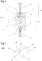
- FIG. 1 schematically shows a cannula unit of an infusion site interface as it is known from the prior art.
- the cannula unit comprises a housing body 2, made from a suitable thermoplastic polymer material.
- the housing body will be suitably mounted on the rest of the interface, e.g. on a base plate (not shown).
- the housing body 2 is provided with a passageway along a longitudinal axis of the body, connecting two opposite ends of the body.
- a pierceable septum 3 is arranged in a corresponding septum seat 3a, thereby sealingly closing this end of the passageway.
- a distal end of an infusion cannula 7 is embedded in the housing body 2.
- the passageway between septum 3 and cannula 7 defines a conical fluid chamber 4 and a fluid conduit 5.
- a flow path between the infusion pump (not shown) and the proximal end of the infusion cannula (not shown) is established, via needle conduit 6a, fluid chamber 4, fluid conduit 5, and cannula conduit 7a, through which during operation liquid medicament is conveyed, as symbolically indicated by dashed arrows.
- Such a cannula unit is particularly useful in combination with flexible cannulas, since for insertion of the cannula into the tissue of a patient, a piercing needle can be arranged in the cannula, with a pointed end protruding from the distal end of the cannula, and a distal end penetrating the septum 3. After insertion, the piercing needle is withdrawn from the cannula. The flow path is then fluidly connected to the tissue of the patient, while the septum sealingly separates the fluid chamber from the environment, thereby keeping the inner volume of the cannula unit sterile.
- the septum can now be used for establishing a fluid connection with an infusion pump, by penetrating the septum with a hollow connector needle 6 shown in Figure 1 .
- separate septums may be used for sealing the flow path after withdrawal of the piercing needle, and for connecting the infusion site interface to the infusion pump.
- a dedicated connector septum may for example be arranged in a lateral wall of the body in such a way that the connector needle penetrates the connector septum perpendicular to the longitudinal axis defined by the cannula. Similar infusion site interfaces are shown in Figure 1D of US 2012/0296290 A1 . If such a variant is combined with a rigid infusion cannula, without the need for a piercing needle, a septum for the piercing needle may be dispensed with.
- a fluid chamber 4 with a diameter larger than the fluid conduit 5 and the subsequent cannula conduit 7a is needed, for preventing a pointed end 6b of a connector needle 6 accidentally cutting into the inner volume wall of the body 2, which can produce chips of polymer material that may occlude the cannula passageway, or may be conveyed into the tissue of the patient, which is both not acceptable. Furthermore, a collision of the needle 6 and the inner wall of the body 3 may distort the connector needle, which can cause leakage of the septum 3.
- infusion site interfaces applying a septum for establishing a fluid connection to the infusion pump will inevitably limit the achievable precision of metering to a certain limit, although the infusion pump may actually be far more precise.
- a further disadvantage of using a pierceable septum and a hollow needle for coupling two fluid systems is the restricted number of coupling/decoupling steps that can be carried out.
- a hollow coupling needle pierces a septum
- the polymer matrix of the elastic septum material is cut.
- the elastic material of the septum may be damaged to such an extent that it cannot properly close any longer the bores produced by the needle.
- the septum starts to leak.
- the hollow needle may even cut out particles of the septum material, which may cause occlusions, or which may be conveyed into the tissue of the patient.
- Such connector devices should have a reduced trapped air volume. If possible the overall dead volume should also be reduced. Furthermore, the connector device should be able to reliably establish a connection and release the connection for a large number of cycles without decrease of the functionality, particular without the risk of leakages or other functional failures.
- a further object of the invention is to provide ambulatory infusion pump devices and components of ambulatory infusion pump devices that comprise such connector devices and/or connector parts.
- the present invention may comprise one or more of the features recited in the attached claims, and/or one or more of the following features and combinations thereof.
- valve seat is made of an elastomeric polymer.
- valve member is a valve ball.
- the resilient element is an elastic structure made of an elastomeric polymer, or is a helical spring.
- the first connector part according to the invention further comprises an infusion cannula fluidly connected to the valve chamber.
- the first connector part further comprises a septum arranged at a distal end of the infusion cannula.
- a first connector part further comprises a piercing needle for temporarily stiffening the infusion cannula, arranged inside the infusion cannula and penetrating the septum.
- the valve member and the septum are one single piece.
- the surface of the recess has the shape of an inverted cone, or forms a section of a hollow sphere.
- the fluid feed conduit has an outlet located on the recess, and one or more notches extending from the outlet across the recess surface to the shell surface of the cone.
- the surface of the recess comprises two or more separated areas.
- a connector device comprises a first connector part according to the invention, and a second connector part according to the invention.
- a connector device further comprises means for pressing together with a certain force the first connector part and the second connector part.
- an advantageous embodiment of a connector device further comprises means for aligning and/or orienting the first connector part and the second connector part in relation to each other.
- an advantageous embodiment of a connector device further comprises means for releasably fixating the first connector part and the second connector part in a certain defined position relative to each other.
- An ambulatory infusion pump unit according to the invention comprises a second connector part according to the invention, or a first connector part according to the invention.
- An infusion site interface according to the invention comprises a first connector part according to the invention, or a second connector part according to the invention.
- An ambulatory infusion pump unit with a second connector part according to the invention can then be coupled with an infusion site interface with a first connector part according to the invention.
- An ambulatory infusion pump unit with a first connector part according to the invention can be coupled with an infusion site interface with a second connector part according to the invention.
- An infusion tubing according to the invention for use with an ambulatory infusion pump comprises a first connector part according to the invention, and/or a second connector part according to the invention.
- Said infusion tubing according to the invention can then be coupled with an infusion site interface according to the invention, and/or an ambulatory infusion pump unit according to the invention.
- An ambulatory infusion pump system comprises a connector device according to the invention.
- An adapter according to the invention comprises a hollow connector needle, a fluid transfer conduit fluidly connected to the hollow transfer needle, and a first connector part according to the invention, or a second connector part according to the invention, wherein the fluid transfer conduit is fluidly connected to the fluid system of the first connector part or second connector part.
- Another adapter according to the invention comprises a connector septum, a fluid chamber sealingly closed by the connector septum, a fluid transfer conduit fluidly connected to the fluid chamber, and a first connector part according to the invention, or a second connector part according to the invention, wherein the fluid transfer conduit is fluidly connected to the fluid system of the first connector part or second connector part.
- the above-mentioned adapters according to the invention allow to connect elements and devices such as ambulatory infusion pump units, infusion site interfaces, and infusion tubing equipped with prior art connector parts such as hollow connector needles, and/or septums to be penetrated by said hollow connector needles to be operationally interconnected with ambulatory infusion pump units, infusion site interfaces, or infusion tubing equipped with first connector parts according to the invention and/or second connector parts according to the invention.
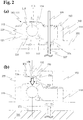
- FIGs 2 (a)-(e) An advantageous embodiment of a connector device according to the invention is disclosed in Figures 2 (a)-(e) .
- the connector device comprises a first, female connector part 110 and a second, male connector part 150.
- the fluid system of the separate female connector part 110 is sealed against the environment.
- the two connector parts are aligned and are pressed onto each other with a certain force, they establish a fluid connection between their respective fluid systems, while the fluid system remains sealed against environment.
- the first, female connector part 110 of a connector device 170 is shown alone, before the removal of the piercing needle 109, in Figure 2(a) .
- the first connector part 110 comprises a housing body 102, in the given example protruding from a base plate 101 of an infusion site interface.
- the housing body 102 is limited by perpendicular walls 119, and has an outer shape (not shown) that is not rotationally symmetric, in order to ensure proper alignment with a second connector part 1 50, as will be discussed further below.
- a flexible infusion cannula 107 is mounted, with a first, distal end being fixed to the body.
- a middle section and a second, proximal end protrude from an underside of the base plate 101 opposite to the first connector part 110.
- a cannula chamber 104 is defined by the volume between distal end of cannula 107 and septum 103, upstream of the inner conduit of the cannula 107.
- a piercing needle 109 is arranged inside the cannula 107, with a pointed end (not shown) protruding from the proximal end of the cannula.
- the piercing needle 109 further penetrates a septum 103 for sealing the fluid system after removal of the piercing needle from the infusion cannula. With the piercing needle 109 inserted in the flexible cannula 107, cannula and needle can be inserted into the tissue of the patient.
- the actual connector part 110 comprises a concave connection cone 118 and a valve 111.
- the connection cone 118 is intended to be pressed against a corresponding connection cone 151 of a second connector part 150, thereby establishing a sealed connection.
- the connector valve 111 sealingly closes the fluid system of the first connector part against environment.
- the valve 111 comprises a valve seat 112 with a circumferential sealing lip 114, and a valve member 113 having the shape of a ball.
- the ball member is mounted on a resilient element 115, which presses with a certain bias force the valve member ball 113 against the circumferential sealing lip 114, thereby sealingly closing the valve.
- valve seat 112 the valve member 113 and the resilient element 115 define an inner volume of the valve, the valve chamber 116.
- a narrow transfer conduit 117 connects the valve chamber 116 with the cannula chamber 104 upstream of the inner conduit of the cannula 107.
- the shown embodiment has a dead volume that is very small compared to a prior art cannula unit, as for example shown in Figure 1 . No voluminous cannula chamber is needed to prevent damages by connector needles. Furthermore essentially the complete fluid system is in the flow path of the liquid medicament, such that no air bubbles can accumulate and the amount of trapped air is minimal.
- Housing body 102 and base plate 101 are made from a suitable rigid polymer material, for example a thermoplastic polymer such as polypropylene.
- the valve member 112 and the connection cone 118, as well as the septum 103 are realized as one single element, made from a suitable elastomeric polymer material, for example rubber, silicone elastomers, thermoplastic elastomers, and the like.
- the spherical valve member 113 is made from a rigid, hard material such as for example hard, non-elastic polymers, steel, glass, ceramics etc, and advantageously has a smooth surface.
- the resilient element 11 5 is made from a suitable elastomeric polymer material, similar as discussed above for the valve seat 112, connection cone 118, and septum 103.
- the elastic material should be able to provide the necessary bias force of the valve member 113 against sealing lip 114. All materials that come into contact with liquid medicament or body tissue must be acceptable for that purpose. A skilled person knows which materials are suitable for the intended function of
- the various elements 102, 112/118/103, 115, 107, 109 may be assembled in different order, depending on the specific manufacturing method.
- a piercing needle 109 threaded on the cannula 107 is provided, and is partially embedded in the polymer matrix of the housing body 102 and the base plate 101 during the manufacture of housing body and base plate, using suitable injection moulding tooling.
- a resilient element 115 is mounted on the base plate, or is produced together with the housing body/base plate using two-component injection moulding techniques. Then the valve ball 113 is placed on the resilient element 115.
- a single component including valve seat, connection cone and septum, is produced e.g.
- the distal end of the piercing needle penetrates the septum, arriving at the connector part shown in Figure 2(a) .
- the distal end of the piercing needle may be equipped with a handle for easing removal of the needle.
- connection cone 151 is arranged at the bottom of a cavity 157 with perpendicular walls 155.
- a spherically shaped recess 153 is located in the centre of the cone 151.
- the radius of the spherical recess 153 is essentially identical to the radius of the valve member 113, since it has the purpose of keeping the valve member ball aligned when the valve is opened, as will be explained further below.
- a fluid feed conduit 1 52 opens toward the outside.
- the fluid feed conduit 152 is connected to the fluid system downstream of an infusion pump, or to an infusion tubing.
- Two notches 154 extending radially from the fluid conduit outlet 158 are provided. The depth of the notches 154 is chosen such that they extend into a central zone of the cone surface around the spherical recess 153, but not into an outer zone of the cone surface that will come into contact with the surface counter cone 118 of a first connector part for establishing.
- these two zones are schematically made visible by a dashed circle defining the inner zone and the outer zone of the cone surface.
- the second connector part 150 is preferably made of a rigid, hard polymer material, such as for example a suitable thermoplastic polymer.
- a rigid, hard polymer material such as for example a suitable thermoplastic polymer.
- Other hard materials such as metal, glass or ceramic material would also be possible, although more expensive and more difficult to manufacture.
- a connector device advantageously comprises primary guiding structures that ensure proper orientation and alignment of the two connector parts.
- such primary guiding structures are provided in the form of interacting guiding elements 119, 155.
- the guiding element 119 of the first connector part 110 is realized as an outer wall 119 of the housing body 102, extending perpendicularly from the base plate 101.
- the guiding element 155 of the second connector part 150 is realized as an inner wall 1 55 of a cavity 157, extending perpendicularly from the bottom of the cavity, at the bottom of which the connector components are arranged (cf. Figure 2(e) ).
- the two guiding walls 119, 155 are shaped in such a way that proper orientation of the two connector parts 110, 150 is given during the connecting process.
- the two connector parts can only be assembled in one, correct orientation.
- a rotationally non-symmetric, egg-shaped form of the walls 155 of the cavity 157 and the outer walls 119 of the housing body 102 allows a coupling only with the two connector parts 110, 150 properly aligned to a coupling axis 161, in one specific rotational arrangement of the two connector parts 110, 150.
- FIG. 2(b) The situation during the connection process is shown in Figure 2(b) , just before the connection of the two connector parts 110, 150 of the disclosed connector device 170 is established.
- the infusion cannula has been inserted into the bodytissue 191 of a patient, and the base plate 101 of the infusion site interface has been attached to the body surface.
- the piercing needle has been removed.
- the two connector parts 110, 150 are properly aligned along axis 171 and correctly oriented to each other.
- the outer guiding wall 119 has been inserted into the corresponding cavity 157 with inner guiding walls 155.
- the guiding walls 119, 155 glide along each other along coupling axis 171.
- Figure 2(c) shows the connector device 170 with established connection between the two connector parts 110, 150.
- the connection cone 151 is pressed with a certain force into the concave connection cone 118. Since the concave connection cone 118 is made of an elastomeric polymer material, while the connection cone 155 is made of a hard, inelastic material, the elastic, resilient cone 118 will be deformed in the zone the two cones come into contact, thereby establishing a reliable fluidly sealed connection between the first and the second connector part.
- the inclination angle of the connection cone 155 in regard to its longitudinal axis is chosen slightly larger than the corresponding inclination angle of its counter cone 118, which results in a circumferential contact zone between the two cones extending from the centre axis 171 radially outwards, with the highest contact pressure close to the centre axis.
- Such an embodiment prevents air being present between the surfaces of the two contacting cones of being pressed into the fluid system. The air is safely squeezed outwards toward atmosphere.
- the spherical recess 153 will touch down on the ball valve member 113.
- the valve member 113 will be pushed downwards toward the base plate, against the bias force of resilient element 115 (shown as dashed arrow). As a result, the valve member ball 113 no longer abuts the sealing lip 114, and the connector valve 111 is open.
- connection cone 151 of the second connector device 150 acts as an actuator for the valve member 113 of valve 111 of the first connector device 110. Since both cone 151 /spherical recess 153 and valve member 113 consist of a hard, inelastic material, while cone 118 is resilient, the movement of the valve member 113 by cone 151 is precise.
- the two connector parts of a connector device as discussed above need to be brought into and hold in a certain, defined position in regard to each other. In this position, a sealingly tight connection between the two cones is achieved, and the valve is kept open by holding the valve ball in its open position against the closing bias force of the resilient element.
- the correct positioning of the two connector parts can be achieved by suitable guiding and locking means that correctly align the two connector parts and keep them in a certain distance to each other.
- Such guiding and locking means may be provided directly in the connecting device, or may be provided in a higher-level system, for example by the means for locking a patch infusion pump on an infusion site interface.
- Corresponding technologies are well known to a skilled person, e.g. releasable clamp mechanisms, bayonet couplings, etc.
- Liquid medicament can now be conveyed downstream from the infusion pump into the infusion cannula toward the body tissue 191 of the patient, as schematically shown as arrows in Figure 2(d) .
- Liquid flows downstream through fluid feed conduit 152, toward the outlet 158 of the conduit. Since the outlet 158 is blocked by valve ball 113, the fluid flows through two conduits between spherical recess 153 and valve member 113, provided by the two notches 154, into the now accessible valve chamber 115. In the valve chamber 115, the liquid flows between valve seat 112 and valve member 113 downward, around the resilient element 115, through the transfer conduit 117 into the cannula chamber 104. From the cannula chamber, the liquid finally flows through cannula conduit 107a towards the proximal end of the cannula, into the tissue 191 of the patient.
- the connecting process is reversed.
- the valve member ball 113 will also move upwards, driven by the biasing force of the resilient element 115, until it reaches the sealing lip 114 of the valve member 112.
- the valve 111 is now sealingly closed again, protecting the fluid system against environment.
- the compressed elastic cone 118 expands, but keeping its cone surface abut the cone surface of cone 151.
- a further upward movement of second part 150 separates the two cones.
- the two connector parts are decoupled.
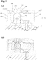
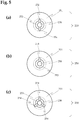
- FIG. 3 shows such a patch pump system, using the connector device of Figure 2 .
- the patch pump system comprises an infusion pump unit 160 and a corresponding infusion site interface 161.
- the infusion site interface 161 comprises a base plate 101, which is attachable with its flat underside to a body surface of a patient, e.g. in the region of an upper arm, a thigh, or the abdomen. Suitable attaching methods are known from the prior art, for example using adhesive layers provided on the underside of the base plate.
- the infusion site interface further comprises a first connector part 110, like the one disclosed in Figure 2 , a cannula 107, and a piercing needle 109 (not shown in Figure 3 ).
- the infusion pump unit 160 comprises a second connector part 150 located in cavity 157, similar to the one disclosed in Figure 2 .
- the infusion pump unit 160 can be releasably mounted to the upper side of the infusion site interface 161, with suitable locking means.
- Locking means that can be used for such a purpose, e.g. releasable catch lock mechanisms or the like, are known to the skilled person and are not shown in detail.
- the locking means in addition to securely mounting the infusion pump unit to the base plate of the infusion site interface, have two additional purposes.
- the locking means act as secondary guiding elements for the connector device, which ensure a correct orientation of the two connector parts before the guiding walls 119, 155 as the primary guiding elements abut each other and ensure a precise alignment during the connection step.
- the locking means will hold the infusion pump unit and the infusion site interface tightly fixed to each other, thereby constantly holding the pressing force on the two connector parts.
- the infusion site interface 161 is placed on the body surface of the patient.
- the temporarily stiffened infusion cannula 107 is inserted into the tissue during manually placing the base plate 101 on the body.
- So called inserter devices are known that allow in a first step attaching a base plate on the body, and in a second step automatically inserting a stiffened cannula into the body tissue, fixedly attaching a cannula hub to the base plate, and subsequently withdrawing the piercing needle.
- Such technologies can also be applied for connector devices as disclosed.
- a hub comprising the housing body with the cannula and the first connector device would be fixedly attached to the base plate after insertion of the temporarily stiffened cannula.
- the piercing needle 109 is removed manually, and one arrives at the now operative infusion site interface 161 in Figure 4(b) .
- the infusion pump device 160 is prepared for being attached to the infusion site interface 161 ( Figure 4(c) ), and is mounted to the base plate ( Figure 4(d) ).
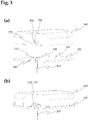
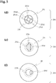
- Figures 5(b) to (f) show further, alternative arrangements of the various elements on the connecting cone of a second connector. Dotted circles mark the borderline between the outer zone of the cone 251, which contacts the counter cone of the other connector part, and the inner zone, which faces toward the valve chamber once the valve is opened.
- Figure 5(b) shows an alternative embodiment where only one notch 254 extends from the outlet 258, thus representing a minimum variant.
- Figure 5(c) shows a further embodiment, with three notches 254, providing an increased flow cross section. Similarly, the amount of notches can be further increased, and/or the geometry of the notches can be changed to more complex forms.
- the area of the spherical recess may be reduced to a very minimum as long as it allows a precise and reliable actuation of the valve member.
- An embodiment with strongly reduced spherical recess area is depicted in Figure 5(d) .
- the notches have been extended to a circular plane 254d perpendicular to the coupling axis, into which the outlet 258 opens.
- the spherical recess has been reduced to four segment shaped protrusions extending from the plane 254d, having a front face 253d that represents a section of the same spherical shape.
- a valve ball of a first connector part will only be in contact with the front faces 253d of the three protrusions, while the liquid can flow through the free volume between the circular plane 254d and the valve ball surface.
- FIG. 5(e) A further embodiment of a connector cone, which does not make use of notches, is shown in Figure 5(e) .
- the fluid feed conduit and its outlet 258e have an oblong cross-section, which extends from the centre of the spherical recess 253 into the inner zone of the cone 251.
- the two outer areas of the outlet 258e that are not within the circular area of the spherical recess 253 open directly toward the valve chamber, once the valve is open.
- a similar approach is applied in the embodiment disclosed in Figure 5(f) .
- the fluid feed channel and its outlet 258f are not aligned to the coupling axis, but are located off-centre. At least a part of the outlet cross-section lies in the inner zone of the cone surface of cone 251. This area of the outlet 258f directly opens toward the valve chamber, once the valve is open.
- first connector part of a connector device is shown in Figure 6 .
- the functional principle of the first connector parts 310, 410 is essentially the same as for the first connector part shown in Figure 2 .
- valve member 31 2 with connection cone 318 does not include a septum for the piercing needle.
- the septum (not shown) is either realized as a separate element, or is dispensed with, for example when rigid cannulas are used.
- the ball shaped valve member has been replaced by an essentially cylindrical valve member 413.
- One end of this cylinder is arranged inside the helical spring 415, thereby ensuring the alignment of valve member 413 and spring 415, and reducing the volume of the valve chamber.
- Another end of the valve member, facing toward the sealing lips 414 of the valve member 412, is realized as a half sphere.
- the helical spring 415 is supported on a circumferential edge of the cylinder.
- the fluid feed conduit of the second connector part has opened in an outlet that is the connected state is at least partially blocked by the valve member of the first connector part.
- Such components can be efficiently produced, e.g. with injection moulding techniques.
Landscapes
- Health & Medical Sciences (AREA)
- Heart & Thoracic Surgery (AREA)
- Hematology (AREA)
- Engineering & Computer Science (AREA)
- Anesthesiology (AREA)
- Biomedical Technology (AREA)
- Life Sciences & Earth Sciences (AREA)
- Animal Behavior & Ethology (AREA)
- General Health & Medical Sciences (AREA)
- Public Health (AREA)
- Veterinary Medicine (AREA)
- Vascular Medicine (AREA)
- Pulmonology (AREA)
- Dermatology (AREA)
- Infusion, Injection, And Reservoir Apparatuses (AREA)
Claims (15)
- Première partie de connecteur (110, 310, 410) destinée à établir une communication fluidique avec une deuxième partie de connecteur selon l'une quelconque des revendications 4 à 7, la première partie de connecteur faisant partie d'une interface de site de perfusion comprenant
une canule de perfusion (107) ;
une soupape (111, 311, 411) destinée à établir une communication fluidique, la soupape comprenant un siège de soupape (112, 312, 412), le siège de soupape comprenant une chambre de soupape (116, 316, 416), et une ouverture circulaire avec une lèvre d'étanchéité circonférentielle (114, 314, 414) ;
un élément de soupape (113, 313, 413), l'élément de soupape étant disposé dans la chambre de soupape, tout en étant capable de fermer de manière étanche l'ouverture circulaire du siège de soupape lorsqu'il est poussé contre l'ouverture circulaire ; et
un élément élastique (115, 315, 415) soumettant l'élément de soupape à une force de rappel poussant l'élément de soupape contre l'ouverture circulaire du siège de soupape ;
dans laquelle le siège de soupape comprend en outre une paroi circonférentielle autour de l'ouverture circulaire, située sur le côté de l'ouverture circulaire opposé à la chambre de soupape ; caractérisée en ce que
la paroi circonférentielle forme un réceptacle concave (118, 318, 418) destiné à recevoir un cône de connexion correspondant d'une deuxième partie de connecteur, le réceptacle concave présentant la forme d'un cône tronqué et étant détourné de la chambre de soupape, l'ouverture circulaire se trouvant au centre du réceptacle concave, et le réceptacle concave présentant un premier angle de cône α par rapport à un axe longitudinal du cône, le premier angle de cône α étant supérieur à un deuxième angle de cône β de la deuxième partie de connecteur, et la différence entre le premier angle de cône α et le deuxième angle de cône β étant inférieure ou égale à environ 20°, avantageusement inférieure ou égale à environ 15°, et plus avantageusement comprise entre environ 5° et environ 15°. - Première partie de connecteur selon la revendication 1, dans laquelle le siège de soupape (112, 312, 412) est constitué d'un polymère élastomère.
- Première partie de connecteur selon la revendication 1 ou 2, dans laquelle l'élément de soupape est une bille de soupape (113, 313).
- Deuxième partie de connecteur (150, 250) destinée à établir une communication fluidique avec une première partie de connecteur selon l'une quelconque des revendications 1 à 3, comprenant
un cône tronqué circulaire droit (151, 251) destiné à être reçu dans un réceptacle concave correspondant d'une première partie de connecteur, la deuxième partie de connecteur présentant un deuxième angle de cône β, et le premier angle de cône α de la première partie de connecteur étant supérieur au deuxième angle de cône β, et la différence entre le premier angle de cône α et le deuxième angle de cône β étant inférieure ou égale à environ 20°, avantageusement inférieure ou égale à environ 15°, et plus avantageusement comprise entre environ 5° et environ 15° ;
une cavité (153, 253, 253d, 253e, 253f) au niveau d'une pointe du cône tronqué, pour l'actionnement d'un élément de soupape d'une première partie de connecteur par poussée de l'élément de soupape contre la force de rappel de l'élément élastique ; et
un conduit d'alimentation en fluide (152) ;
dans laquelle le conduit d'alimentation en fluide comporte une ou plusieurs sorties (154, 254, 254d, 258, 258e, 258f) débouchant au moins partiellement sur la surface d'enveloppe du cône tronqué (151, 251). - Deuxième partie de connecteur selon la revendication 4, dans laquelle la surface de la cavité (153, 253, 253d, 253e, 253f) présente la forme d'un cône inversé, ou forme une section d'une sphère creuse.
- Deuxième partie de connecteur selon la revendication 4 ou 5, dans laquelle le conduit d'alimentation en fluide (152) comporte une sortie (158, 258) située sur la cavité (153, 253), et une ou plusieurs encoches (154, 254) s'étendant à partir de la sortie, à travers la surface de cavité, vers la surface d'enveloppe du cône (151, 251).
- Deuxième partie de connecteur selon l'une quelconque des revendications 4 à 6, dans laquelle la surface de la cavité (153, 253, 253d) comprend deux ou plusieurs zones séparées.
- Dispositif de connexion (170) comprenant une première partie de connecteur selon l'une quelconque des revendications 1 à 3, et une deuxième partie de connecteur selon l'une quelconque des revendications 4 à 7.
- Dispositif de connexion selon la revendication 8, comprenant en outre un moyen permettant de presser la première partie de connecteur et la deuxième partie de connecteur ensemble avec une certaine force.
- Dispositif de connexion selon la revendication 8 ou 9, comprenant en outre un moyen permettant d'aligner et/ou d'orienter la première partie de connecteur et la deuxième partie de connecteur l'une par rapport à l'autre ; ainsi qu'un moyen permettant de fixer de façon amovible la première partie de connecteur et la deuxième partie de connecteur dans une certaine position définie l'une par rapport à l'autre.
- Unité de pompe de perfusion ambulatoire (160) comprenant une deuxième partie de connecteur selon l'une quelconque des revendications 4 à 7, ou une première partie de connecteur selon l'une quelconque des revendications 1 à 3.
- Interface de site de perfusion (161) comprenant une première partie de connecteur selon l'une quelconque des revendications 1 à 3, ou une deuxième partie de connecteur selon l'une quelconque des revendications 4 à 7.
- Tube de perfusion destiné à être utilisé avec une pompe de perfusion ambulatoire, comprenant une première partie de connecteur selon l'une quelconque des revendications 1 à 3, et/ou une deuxième partie de connecteur selon l'une quelconque des revendications 4 à 7.
- Adaptateur comprenant une aiguille de connecteur creuse (6), un conduit de transfert de fluide en communication fluidique avec l'aiguille de connecteur creuse, et une première partie de connecteur selon l'une quelconque des revendications 1 à 3, ou une deuxième partie de connecteur selon l'une quelconque des revendications 4 à 7, dans lequel le conduit de transfert de fluide est en communication fluidique avec le système de fluide de la partie de connecteur ou de la deuxième partie de connecteur.
- Adaptateur comprenant un septum de connecteur (3), une chambre à fluide (4) fermée de façon étanche par le septum de connecteur, un conduit de transfert de fluide en communication fluidique avec la chambre à fluide, et une première partie de connecteur selon l'une quelconque des revendications 1 à 3, ou une deuxième partie de connecteur selon l'une quelconque des revendications 4 à 7, dans lequel le conduit de transfert de fluide est en communication fluidique avec le système de fluide de la première partie de connecteur ou de la deuxième partie de connecteur.
Priority Applications (8)
| Application Number | Priority Date | Filing Date | Title |
|---|---|---|---|
| EP16186167.9A EP3290073B1 (fr) | 2016-08-29 | 2016-08-29 | Dispositif de connecteur |
| DK16186167.9T DK3290073T3 (da) | 2016-08-29 | 2016-08-29 | Forbindelsesanordning |
| JP2019510422A JP7026106B2 (ja) | 2016-08-29 | 2017-08-18 | コネクタデバイス |
| BR112019002015-2A BR112019002015B1 (pt) | 2016-08-29 | 2017-08-18 | Primeira e segunda peça conectora, dispositivo conector, unidade de bomba de infusão ambulatorial, interface de local de infusão, tubulação de infusão, sistema de bomba de infusão ambulatorial e adaptador |
| RU2019107020A RU2750834C2 (ru) | 2016-08-29 | 2017-08-18 | Соединительное устройство |
| AU2017320513A AU2017320513B2 (en) | 2016-08-29 | 2017-08-18 | Connector device |
| PCT/EP2017/070906 WO2018041645A1 (fr) | 2016-08-29 | 2017-08-18 | Dispositif de raccordement |
| US16/326,577 US11406758B2 (en) | 2016-08-29 | 2017-08-18 | Connector device |
Applications Claiming Priority (1)
| Application Number | Priority Date | Filing Date | Title |
|---|---|---|---|
| EP16186167.9A EP3290073B1 (fr) | 2016-08-29 | 2016-08-29 | Dispositif de connecteur |
Publications (2)
| Publication Number | Publication Date |
|---|---|
| EP3290073A1 EP3290073A1 (fr) | 2018-03-07 |
| EP3290073B1 true EP3290073B1 (fr) | 2020-12-09 |
Family
ID=56853469
Family Applications (1)
| Application Number | Title | Priority Date | Filing Date |
|---|---|---|---|
| EP16186167.9A Active EP3290073B1 (fr) | 2016-08-29 | 2016-08-29 | Dispositif de connecteur |
Country Status (8)
| Country | Link |
|---|---|
| US (1) | US11406758B2 (fr) |
| EP (1) | EP3290073B1 (fr) |
| JP (1) | JP7026106B2 (fr) |
| AU (1) | AU2017320513B2 (fr) |
| BR (1) | BR112019002015B1 (fr) |
| DK (1) | DK3290073T3 (fr) |
| RU (1) | RU2750834C2 (fr) |
| WO (1) | WO2018041645A1 (fr) |
Families Citing this family (8)
| Publication number | Priority date | Publication date | Assignee | Title |
|---|---|---|---|---|
| US8881774B2 (en) * | 2007-12-31 | 2014-11-11 | Deka Research & Development Corp. | Apparatus, system and method for fluid delivery |
| US9617020B2 (en) * | 2013-07-03 | 2017-04-11 | Deka Products Limited Partnership | Apparatus, system and method for fluid delivery |
| EP3329956A1 (fr) | 2016-11-30 | 2018-06-06 | Roche Diabetes Care GmbH | Procédé de production d'une canule |
| WO2019021434A1 (fr) * | 2017-07-27 | 2019-01-31 | アネスト岩田株式会社 | Prise d'alimentation en gaz |
| CN114630688B (zh) * | 2020-03-23 | 2023-08-08 | 泰尔茂株式会社 | 给药液装置 |
| WO2022202279A1 (fr) * | 2021-03-25 | 2022-09-29 | テルモ株式会社 | Dispositif d'administration de solution medicamenteuse |
| CN115849038B (zh) * | 2022-12-30 | 2023-10-03 | 浙江天能电源材料有限公司 | 一种往复式废铅膏布料定量给料装置及方法 |
| CN116099079B (zh) * | 2023-03-31 | 2023-11-21 | 常州瑞神安医疗器械有限公司 | 一种植入式药物输注泵 |
Family Cites Families (15)
| Publication number | Priority date | Publication date | Assignee | Title |
|---|---|---|---|---|
| JPS5218222A (en) * | 1975-08-04 | 1977-02-10 | Tsurukichi Sakuma | Fluid joint |
| US6089541A (en) * | 1998-09-10 | 2000-07-18 | Halkey-Roberts Corporation | Valve having a valve body and a deformable stem therein |
| US6572586B1 (en) | 2000-07-25 | 2003-06-03 | Animas Corporation | Low profile infusion set |
| GB0224178D0 (en) | 2002-10-17 | 2002-11-27 | Michel David | Grass brush apparatus |
| FR2852780B1 (fr) | 2003-03-24 | 2006-02-24 | Jean Claude Cuadrado | Dispositif pour le remplissage des trous de carottage d'une pelouse |
| WO2007056504A1 (fr) | 2005-11-08 | 2007-05-18 | M2 Medical A/S | Systeme de pompe de perfusion |
| US7891637B2 (en) | 2006-11-07 | 2011-02-22 | Angstrom Power Incorporated | Magnetic fluid coupling assemblies and methods |
| DK2146760T3 (en) * | 2007-04-30 | 2019-01-28 | Medtronic Minimed Inc | FILLING OF RESERVOIR, BUBBLE MANAGEMENT AND DELIVERY SYSTEMS FOR INFUSION MEDIA AND PROCEDURES |
| DE102007022899A1 (de) | 2007-05-14 | 2008-11-20 | Claas Selbstfahrende Erntemaschinen Gmbh | Landwirtschaftliche Arbeitsmaschine |
| US20080303267A1 (en) * | 2007-06-05 | 2008-12-11 | Schnell William J | Fluid flow connector permitting forceful lateral separation |
| EP2528642B1 (fr) | 2010-01-25 | 2017-11-22 | F. Hoffmann-La Roche AG | Procédé de fabrication d'un élément doté d'une canule, canule, élément doté d'une canule et tête d'insertion |
| US8900206B2 (en) | 2011-02-22 | 2014-12-02 | Medtronic Minimed, Inc. | Pressure vented fluid reservoir for a fluid infusion device |
| WO2013153722A1 (fr) * | 2012-04-13 | 2013-10-17 | テルモ株式会社 | Structure de connexion de tube |
| WO2014173772A1 (fr) * | 2013-04-22 | 2014-10-30 | Sanofi-Aventis Deutschland Gmbh | Dispositif capteur à oled |
| US20150105731A1 (en) * | 2013-10-14 | 2015-04-16 | Medtronic Minimed, Inc. | Therapeutic Agent Injection Device and Body |
-
2016
- 2016-08-29 EP EP16186167.9A patent/EP3290073B1/fr active Active
- 2016-08-29 DK DK16186167.9T patent/DK3290073T3/da active
-
2017
- 2017-08-18 WO PCT/EP2017/070906 patent/WO2018041645A1/fr active Application Filing
- 2017-08-18 AU AU2017320513A patent/AU2017320513B2/en active Active
- 2017-08-18 JP JP2019510422A patent/JP7026106B2/ja active Active
- 2017-08-18 US US16/326,577 patent/US11406758B2/en active Active
- 2017-08-18 RU RU2019107020A patent/RU2750834C2/ru active
- 2017-08-18 BR BR112019002015-2A patent/BR112019002015B1/pt active IP Right Grant
Non-Patent Citations (1)
| Title |
|---|
| None * |
Also Published As
| Publication number | Publication date |
|---|---|
| BR112019002015B1 (pt) | 2023-01-10 |
| EP3290073A1 (fr) | 2018-03-07 |
| BR112019002015A2 (pt) | 2019-05-14 |
| AU2017320513A1 (en) | 2019-02-14 |
| JP7026106B2 (ja) | 2022-02-25 |
| US11406758B2 (en) | 2022-08-09 |
| US20190240401A1 (en) | 2019-08-08 |
| WO2018041645A1 (fr) | 2018-03-08 |
| JP2019524358A (ja) | 2019-09-05 |
| RU2019107020A (ru) | 2020-09-29 |
| AU2017320513B2 (en) | 2022-09-29 |
| RU2750834C2 (ru) | 2021-07-05 |
| DK3290073T3 (da) | 2021-02-15 |
| RU2019107020A3 (fr) | 2020-11-30 |
Similar Documents
| Publication | Publication Date | Title |
|---|---|---|
| EP3290073B1 (fr) | Dispositif de connecteur | |
| CN101715353B (zh) | 插管和输送设备 | |
| US10946138B2 (en) | Subcutaneous infusion set with side port fluid connector | |
| JP7535639B2 (ja) | 単一または複数の容器のための貯留デバイス | |
| US10898643B2 (en) | Sealing between a cannula part and a fluid path | |
| US6010494A (en) | Connection system for medical applications | |
| JP4064422B2 (ja) | 医療器具用のシール弁、接続ポート、混注管、輸液回路の接続器具及び輸液回路の接続システム | |
| JP7414905B2 (ja) | 携帯用流体移送装置およびシステム | |
| EP3378516B1 (fr) | Dispositif de perfusion de fluide et réservoir de fluide associé et conceptions d'ensemble d'étanchéité | |
| JP2011511689A (ja) | カニューレと送出部品との間の成形連結部 | |
| EP2654827A2 (fr) | Systèmes et procédés d'alignement et de connexion | |
| WO2009033032A1 (fr) | Dispositif de perfusion et son procédé d'utilisation et de fabrication | |
| SK74194A3 (en) | Medical valve and method of liquid transport | |
| KR20210114406A (ko) | 주입 펌프 유닛용 크래들 | |
| CN116528937A (zh) | 凸连接器以及医疗器具 | |
| JP6709777B2 (ja) | オスコネクタ及び輸液セット | |
| JP6741209B2 (ja) | フィルタ組立品 | |
| EP3672681B1 (fr) | Septum auto-obturant | |
| CN115920169A (zh) | 具有可旋转针座的输注套件和方法 | |
| JPWO2008059834A1 (ja) | 仮固定部材、コネクタ組立体および輸液チューブセット |
Legal Events
| Date | Code | Title | Description |
|---|---|---|---|
| PUAI | Public reference made under article 153(3) epc to a published international application that has entered the european phase |
Free format text: ORIGINAL CODE: 0009012 |
|
| STAA | Information on the status of an ep patent application or granted ep patent |
Free format text: STATUS: THE APPLICATION HAS BEEN PUBLISHED |
|
| AK | Designated contracting states |
Kind code of ref document: A1 Designated state(s): AL AT BE BG CH CY CZ DE DK EE ES FI FR GB GR HR HU IE IS IT LI LT LU LV MC MK MT NL NO PL PT RO RS SE SI SK SM TR |
|
| AX | Request for extension of the european patent |
Extension state: BA ME |
|
| RIN1 | Information on inventor provided before grant (corrected) |
Inventor name: LIST, HANS |
|
| STAA | Information on the status of an ep patent application or granted ep patent |
Free format text: STATUS: REQUEST FOR EXAMINATION WAS MADE |
|
| 17P | Request for examination filed |
Effective date: 20180905 |
|
| RBV | Designated contracting states (corrected) |
Designated state(s): AL AT BE BG CH CY CZ DE DK EE ES FI FR GB GR HR HU IE IS IT LI LT LU LV MC MK MT NL NO PL PT RO RS SE SI SK SM TR |
|
| STAA | Information on the status of an ep patent application or granted ep patent |
Free format text: STATUS: EXAMINATION IS IN PROGRESS |
|
| 17Q | First examination report despatched |
Effective date: 20181218 |
|
| GRAP | Despatch of communication of intention to grant a patent |
Free format text: ORIGINAL CODE: EPIDOSNIGR1 |
|
| STAA | Information on the status of an ep patent application or granted ep patent |
Free format text: STATUS: GRANT OF PATENT IS INTENDED |
|
| RIC1 | Information provided on ipc code assigned before grant |
Ipc: A61M 5/168 20060101ALI20200619BHEP Ipc: A61M 5/158 20060101AFI20200619BHEP Ipc: A61M 39/10 20060101ALI20200619BHEP Ipc: A61M 39/26 20060101ALI20200619BHEP Ipc: A61M 5/142 20060101ALI20200619BHEP Ipc: A61M 39/02 20060101ALI20200619BHEP |
|
| INTG | Intention to grant announced |
Effective date: 20200709 |
|
| GRAS | Grant fee paid |
Free format text: ORIGINAL CODE: EPIDOSNIGR3 |
|
| GRAA | (expected) grant |
Free format text: ORIGINAL CODE: 0009210 |
|
| STAA | Information on the status of an ep patent application or granted ep patent |
Free format text: STATUS: THE PATENT HAS BEEN GRANTED |
|
| AK | Designated contracting states |
Kind code of ref document: B1 Designated state(s): AL AT BE BG CH CY CZ DE DK EE ES FI FR GB GR HR HU IE IS IT LI LT LU LV MC MK MT NL NO PL PT RO RS SE SI SK SM TR |
|
| REG | Reference to a national code |
Ref country code: GB Ref legal event code: FG4D |
|
| REG | Reference to a national code |
Ref country code: AT Ref legal event code: REF Ref document number: 1342738 Country of ref document: AT Kind code of ref document: T Effective date: 20201215 Ref country code: CH Ref legal event code: EP |
|
| REG | Reference to a national code |
Ref country code: DE Ref legal event code: R096 Ref document number: 602016049333 Country of ref document: DE |
|
| REG | Reference to a national code |
Ref country code: IE Ref legal event code: FG4D |
|
| REG | Reference to a national code |
Ref country code: DK Ref legal event code: T3 Effective date: 20210209 |
|
| REG | Reference to a national code |
Ref country code: NL Ref legal event code: FP |
|
| PG25 | Lapsed in a contracting state [announced via postgrant information from national office to epo] |
Ref country code: GR Free format text: LAPSE BECAUSE OF FAILURE TO SUBMIT A TRANSLATION OF THE DESCRIPTION OR TO PAY THE FEE WITHIN THE PRESCRIBED TIME-LIMIT Effective date: 20210310 Ref country code: FI Free format text: LAPSE BECAUSE OF FAILURE TO SUBMIT A TRANSLATION OF THE DESCRIPTION OR TO PAY THE FEE WITHIN THE PRESCRIBED TIME-LIMIT Effective date: 20201209 Ref country code: RS Free format text: LAPSE BECAUSE OF FAILURE TO SUBMIT A TRANSLATION OF THE DESCRIPTION OR TO PAY THE FEE WITHIN THE PRESCRIBED TIME-LIMIT Effective date: 20201209 Ref country code: NO Free format text: LAPSE BECAUSE OF FAILURE TO SUBMIT A TRANSLATION OF THE DESCRIPTION OR TO PAY THE FEE WITHIN THE PRESCRIBED TIME-LIMIT Effective date: 20210309 |
|
| REG | Reference to a national code |
Ref country code: AT Ref legal event code: MK05 Ref document number: 1342738 Country of ref document: AT Kind code of ref document: T Effective date: 20201209 |
|
| PG25 | Lapsed in a contracting state [announced via postgrant information from national office to epo] |
Ref country code: SE Free format text: LAPSE BECAUSE OF FAILURE TO SUBMIT A TRANSLATION OF THE DESCRIPTION OR TO PAY THE FEE WITHIN THE PRESCRIBED TIME-LIMIT Effective date: 20201209 Ref country code: BG Free format text: LAPSE BECAUSE OF FAILURE TO SUBMIT A TRANSLATION OF THE DESCRIPTION OR TO PAY THE FEE WITHIN THE PRESCRIBED TIME-LIMIT Effective date: 20210309 Ref country code: LV Free format text: LAPSE BECAUSE OF FAILURE TO SUBMIT A TRANSLATION OF THE DESCRIPTION OR TO PAY THE FEE WITHIN THE PRESCRIBED TIME-LIMIT Effective date: 20201209 |
|
| PG25 | Lapsed in a contracting state [announced via postgrant information from national office to epo] |
Ref country code: HR Free format text: LAPSE BECAUSE OF FAILURE TO SUBMIT A TRANSLATION OF THE DESCRIPTION OR TO PAY THE FEE WITHIN THE PRESCRIBED TIME-LIMIT Effective date: 20201209 |
|
| REG | Reference to a national code |
Ref country code: LT Ref legal event code: MG9D |
|
| PG25 | Lapsed in a contracting state [announced via postgrant information from national office to epo] |
Ref country code: PT Free format text: LAPSE BECAUSE OF FAILURE TO SUBMIT A TRANSLATION OF THE DESCRIPTION OR TO PAY THE FEE WITHIN THE PRESCRIBED TIME-LIMIT Effective date: 20210409 Ref country code: RO Free format text: LAPSE BECAUSE OF FAILURE TO SUBMIT A TRANSLATION OF THE DESCRIPTION OR TO PAY THE FEE WITHIN THE PRESCRIBED TIME-LIMIT Effective date: 20201209 Ref country code: SK Free format text: LAPSE BECAUSE OF FAILURE TO SUBMIT A TRANSLATION OF THE DESCRIPTION OR TO PAY THE FEE WITHIN THE PRESCRIBED TIME-LIMIT Effective date: 20201209 Ref country code: SM Free format text: LAPSE BECAUSE OF FAILURE TO SUBMIT A TRANSLATION OF THE DESCRIPTION OR TO PAY THE FEE WITHIN THE PRESCRIBED TIME-LIMIT Effective date: 20201209 Ref country code: LT Free format text: LAPSE BECAUSE OF FAILURE TO SUBMIT A TRANSLATION OF THE DESCRIPTION OR TO PAY THE FEE WITHIN THE PRESCRIBED TIME-LIMIT Effective date: 20201209 Ref country code: EE Free format text: LAPSE BECAUSE OF FAILURE TO SUBMIT A TRANSLATION OF THE DESCRIPTION OR TO PAY THE FEE WITHIN THE PRESCRIBED TIME-LIMIT Effective date: 20201209 Ref country code: CZ Free format text: LAPSE BECAUSE OF FAILURE TO SUBMIT A TRANSLATION OF THE DESCRIPTION OR TO PAY THE FEE WITHIN THE PRESCRIBED TIME-LIMIT Effective date: 20201209 |
|
| PG25 | Lapsed in a contracting state [announced via postgrant information from national office to epo] |
Ref country code: PL Free format text: LAPSE BECAUSE OF FAILURE TO SUBMIT A TRANSLATION OF THE DESCRIPTION OR TO PAY THE FEE WITHIN THE PRESCRIBED TIME-LIMIT Effective date: 20201209 Ref country code: AT Free format text: LAPSE BECAUSE OF FAILURE TO SUBMIT A TRANSLATION OF THE DESCRIPTION OR TO PAY THE FEE WITHIN THE PRESCRIBED TIME-LIMIT Effective date: 20201209 |
|
| REG | Reference to a national code |
Ref country code: DE Ref legal event code: R097 Ref document number: 602016049333 Country of ref document: DE |
|
| PG25 | Lapsed in a contracting state [announced via postgrant information from national office to epo] |
Ref country code: IS Free format text: LAPSE BECAUSE OF FAILURE TO SUBMIT A TRANSLATION OF THE DESCRIPTION OR TO PAY THE FEE WITHIN THE PRESCRIBED TIME-LIMIT Effective date: 20210409 |
|
| PLBE | No opposition filed within time limit |
Free format text: ORIGINAL CODE: 0009261 |
|
| STAA | Information on the status of an ep patent application or granted ep patent |
Free format text: STATUS: NO OPPOSITION FILED WITHIN TIME LIMIT |
|
| PG25 | Lapsed in a contracting state [announced via postgrant information from national office to epo] |
Ref country code: AL Free format text: LAPSE BECAUSE OF FAILURE TO SUBMIT A TRANSLATION OF THE DESCRIPTION OR TO PAY THE FEE WITHIN THE PRESCRIBED TIME-LIMIT Effective date: 20201209 |
|
| 26N | No opposition filed |
Effective date: 20210910 |
|
| PG25 | Lapsed in a contracting state [announced via postgrant information from national office to epo] |
Ref country code: SI Free format text: LAPSE BECAUSE OF FAILURE TO SUBMIT A TRANSLATION OF THE DESCRIPTION OR TO PAY THE FEE WITHIN THE PRESCRIBED TIME-LIMIT Effective date: 20201209 |
|
| PG25 | Lapsed in a contracting state [announced via postgrant information from national office to epo] |
Ref country code: ES Free format text: LAPSE BECAUSE OF FAILURE TO SUBMIT A TRANSLATION OF THE DESCRIPTION OR TO PAY THE FEE WITHIN THE PRESCRIBED TIME-LIMIT Effective date: 20201209 |
|
| PG25 | Lapsed in a contracting state [announced via postgrant information from national office to epo] |
Ref country code: MC Free format text: LAPSE BECAUSE OF FAILURE TO SUBMIT A TRANSLATION OF THE DESCRIPTION OR TO PAY THE FEE WITHIN THE PRESCRIBED TIME-LIMIT Effective date: 20201209 |
|
| REG | Reference to a national code |
Ref country code: BE Ref legal event code: MM Effective date: 20210831 |
|
| PG25 | Lapsed in a contracting state [announced via postgrant information from national office to epo] |
Ref country code: IS Free format text: LAPSE BECAUSE OF FAILURE TO SUBMIT A TRANSLATION OF THE DESCRIPTION OR TO PAY THE FEE WITHIN THE PRESCRIBED TIME-LIMIT Effective date: 20210409 Ref country code: LU Free format text: LAPSE BECAUSE OF NON-PAYMENT OF DUE FEES Effective date: 20210829 |
|
| PG25 | Lapsed in a contracting state [announced via postgrant information from national office to epo] |
Ref country code: IE Free format text: LAPSE BECAUSE OF NON-PAYMENT OF DUE FEES Effective date: 20210829 Ref country code: BE Free format text: LAPSE BECAUSE OF NON-PAYMENT OF DUE FEES Effective date: 20210831 |
|
| PG25 | Lapsed in a contracting state [announced via postgrant information from national office to epo] |
Ref country code: HU Free format text: LAPSE BECAUSE OF FAILURE TO SUBMIT A TRANSLATION OF THE DESCRIPTION OR TO PAY THE FEE WITHIN THE PRESCRIBED TIME-LIMIT; INVALID AB INITIO Effective date: 20160829 |
|
| PG25 | Lapsed in a contracting state [announced via postgrant information from national office to epo] |
Ref country code: CY Free format text: LAPSE BECAUSE OF FAILURE TO SUBMIT A TRANSLATION OF THE DESCRIPTION OR TO PAY THE FEE WITHIN THE PRESCRIBED TIME-LIMIT Effective date: 20201209 |
|
| PGFP | Annual fee paid to national office [announced via postgrant information from national office to epo] |
Ref country code: IT Payment date: 20230720 Year of fee payment: 8 Ref country code: GB Payment date: 20230720 Year of fee payment: 8 Ref country code: CH Payment date: 20230902 Year of fee payment: 8 |
|
| PGFP | Annual fee paid to national office [announced via postgrant information from national office to epo] |
Ref country code: FR Payment date: 20230720 Year of fee payment: 8 Ref country code: DK Payment date: 20230725 Year of fee payment: 8 Ref country code: DE Payment date: 20230720 Year of fee payment: 8 |
|
| PG25 | Lapsed in a contracting state [announced via postgrant information from national office to epo] |
Ref country code: MK Free format text: LAPSE BECAUSE OF FAILURE TO SUBMIT A TRANSLATION OF THE DESCRIPTION OR TO PAY THE FEE WITHIN THE PRESCRIBED TIME-LIMIT Effective date: 20201209 |
|
| PG25 | Lapsed in a contracting state [announced via postgrant information from national office to epo] |
Ref country code: TR Free format text: LAPSE BECAUSE OF FAILURE TO SUBMIT A TRANSLATION OF THE DESCRIPTION OR TO PAY THE FEE WITHIN THE PRESCRIBED TIME-LIMIT Effective date: 20201209 |
|
| PGFP | Annual fee paid to national office [announced via postgrant information from national office to epo] |
Ref country code: NL Payment date: 20240723 Year of fee payment: 9 |