EP3289987B1 - Werkzeuglos montierbares/demontierbares medizinisches instrument - Google Patents
Werkzeuglos montierbares/demontierbares medizinisches instrument Download PDFInfo
- Publication number
- EP3289987B1 EP3289987B1 EP17189576.6A EP17189576A EP3289987B1 EP 3289987 B1 EP3289987 B1 EP 3289987B1 EP 17189576 A EP17189576 A EP 17189576A EP 3289987 B1 EP3289987 B1 EP 3289987B1
- Authority
- EP
- European Patent Office
- Prior art keywords
- medical instrument
- bearing
- guide
- section
- hand lever
- Prior art date
- Legal status (The legal status is an assumption and is not a legal conclusion. Google has not performed a legal analysis and makes no representation as to the accuracy of the status listed.)
- Active
Links
Images


Classifications
-
- A—HUMAN NECESSITIES
- A61—MEDICAL OR VETERINARY SCIENCE; HYGIENE
- A61B—DIAGNOSIS; SURGERY; IDENTIFICATION
- A61B17/00—Surgical instruments, devices or methods
- A61B17/28—Surgical forceps
- A61B17/2812—Surgical forceps with a single pivotal connection
- A61B17/2816—Pivots
-
- A—HUMAN NECESSITIES
- A61—MEDICAL OR VETERINARY SCIENCE; HYGIENE
- A61B—DIAGNOSIS; SURGERY; IDENTIFICATION
- A61B17/00—Surgical instruments, devices or methods
- A61B17/28—Surgical forceps
- A61B17/2812—Surgical forceps with a single pivotal connection
-
- B—PERFORMING OPERATIONS; TRANSPORTING
- B25—HAND TOOLS; PORTABLE POWER-DRIVEN TOOLS; MANIPULATORS
- B25B—TOOLS OR BENCH DEVICES NOT OTHERWISE PROVIDED FOR, FOR FASTENING, CONNECTING, DISENGAGING, OR HOLDING
- B25B7/00—Pliers; Other hand-held gripping tools with jaws on pivoted limbs; Details applicable generally to pivoted-limb hand tools
- B25B7/02—Jaws
-
- B—PERFORMING OPERATIONS; TRANSPORTING
- B25—HAND TOOLS; PORTABLE POWER-DRIVEN TOOLS; MANIPULATORS
- B25B—TOOLS OR BENCH DEVICES NOT OTHERWISE PROVIDED FOR, FOR FASTENING, CONNECTING, DISENGAGING, OR HOLDING
- B25B7/00—Pliers; Other hand-held gripping tools with jaws on pivoted limbs; Details applicable generally to pivoted-limb hand tools
- B25B7/06—Joints
- B25B7/08—Joints with fixed fulcrum
-
- A—HUMAN NECESSITIES
- A61—MEDICAL OR VETERINARY SCIENCE; HYGIENE
- A61B—DIAGNOSIS; SURGERY; IDENTIFICATION
- A61B17/00—Surgical instruments, devices or methods
- A61B17/32—Surgical cutting instruments
- A61B17/3201—Scissors
-
- A—HUMAN NECESSITIES
- A61—MEDICAL OR VETERINARY SCIENCE; HYGIENE
- A61B—DIAGNOSIS; SURGERY; IDENTIFICATION
- A61B90/00—Instruments, implements or accessories specially adapted for surgery or diagnosis and not covered by any of the groups A61B1/00 - A61B50/00, e.g. for luxation treatment or for protecting wound edges
- A61B90/08—Accessories or related features not otherwise provided for
- A61B2090/0813—Accessories designed for easy sterilising, i.e. re-usable
-
- A—HUMAN NECESSITIES
- A61—MEDICAL OR VETERINARY SCIENCE; HYGIENE
- A61B—DIAGNOSIS; SURGERY; IDENTIFICATION
- A61B90/00—Instruments, implements or accessories specially adapted for surgery or diagnosis and not covered by any of the groups A61B1/00 - A61B50/00, e.g. for luxation treatment or for protecting wound edges
- A61B90/70—Cleaning devices specially adapted for surgical instruments
Definitions
- the present invention relates to a medical instrument, such as a clamp, a pair of pliers or another scissor-like hand tool, with a first hand lever, which has a handle section provided for manual operation at its proximal end, a working section, for example in the manner of a branch, for Gripping, clamping or cutting an object at its distal end and an intermediate bearing section which is engaged by a bearing element in order to allow pivotability about an axis of rotation between the first hand lever and a second hand lever, the second hand lever having a handle section at its proximal end , has a working section at its distal end and a guide section in between, which is engaged by the bearing element, with a bearing being designed in such a way that the two hand levers are supported in the operating position by means of the bearing element in a form-fitting manner but can be pivoted relative to one another, and d that the hand levers can be removed without tools in a cleaning position, the male bearing element being provided integrally in the bearing section of the first hand
- a forceps-like medical instrument which consists of a first hand lever having a guide plate and a second hand lever having a bearing plate, which are pivotably connected to one another via a bearing pin arranged in the area of the guide plate and the bearing plate and provided with a radially expanded head part, wherein the bearing plate forms a receiving groove in each of its longitudinal edge regions, into which the guide plate engages in its operating position, the bearing plate between the receiving grooves extending over the entire width of the bearing plate has a depression extending and the guide plate can be rotated from its operating position into a cleaning position relative to the bearing plate, in which the guide plate overlaps with the depression and a spacer element is provided in the region of the depression between the guide plate and the bearing plate, the height of which in the direction of the Pivot is equal to or smaller than the depth of the recess.
- the DE 20 2010 010 843 U1 discloses a scissors-like or pliers-like medical hand tool with two two-armed hand levers, which are connected to one another in an articulated manner in the area of two plate-like flattened central sections by a pivot pin and can be pivoted relative to one another, with one preferably short lever arm of each hand lever being designed as a tool and the respective second, longer lever arm designed as a handle, the pivot pin fixed immovably in the flattened central section of one hand lever being provided with an annular flange which is at a distance from the central section of the first hand lever, in which the pivot pin is fixed, which is at least twice the thickness of the one on the pivot pin mounted middle section of the second hand lever corresponds, so that the second hand lever in the maximum pivoting position of the two hand levers on the pivot pin is at least so far displaceable in a position in which the opposite to each other lying inner surfaces of the flattened middle sections and the pivot pins are exposed.
- the DE 20 2011 107 977 U1 again discloses a scissors-like or pliers-like medical instrument with a first and a second hand lever, which each have a handle part and a tool part and which are pivotally connected to one another via a bearing pin provided with a radially expanded head part, the first hand lever being in the area between its handle part and its tool part forms a guide plate and the second hand lever forms a bearing plate in the area between its handle part and its tool part, in the area of which the bearing pin is fixedly arranged, the guide plate having an opening for pivotably receiving the bearing pin and the guide plate and the bearing plate in the normal operating state of the instrument touch flat, with the breakthrough of the guide plate as an in Longitudinally extending slot is formed and the slot in the edge area of its end area adjacent to the tool part has a first widened indentation and in the edge area of its opposite end area in the longitudinal direction a second widened indentation, in which the head part of the bearing pin can be selectively accommodated and the first indentation
- the DE 20 2009 002 367 U1 discloses a medical instrument, in particular forceps, made of two halves which are connected to one another via a first and a second end, the second end having at least one guide channel for at least one rotary surface of the first end, the guide channel only partially delimited by a base is.
- the object of the invention is to avoid or at least mitigate the disadvantages of the prior art, and in particular to provide a locking connection of the two hand levers which can be dismantled/detached without tools and which is as easy as possible to clean.
- the object of the invention is achieved with a generic medical instrument in that the circumferential guide gap is interrupted by a plurality of recesses distributed in the circumferential direction.
- the bearing is designed in the manner of a bayonet lock. This enables both tool-free assembly and disassembly.
- the area in which the bayonet lock is closed, i.e. the two hand levers are in a form-fitting manner, corresponds to the operating position.
- the bearing element is essentially round, ie circular in the pivot plane (the plane perpendicular to the axis of rotation) and has preferably evenly distributed, for example 2, 3, 4, 5 or 6 projections/overhangs in the circumferential direction. These are used for the form-fitting connection in the manner of a bayonet catch of the first hand lever with the second hand lever.
- the projections are trapezoidal.
- an advantageous embodiment provides that the trapezoidal projections have a longer side edge radially on the outside than radially on the inside. It is advantageous here if the number and the position along the circumference of the respective projections/overhangs correspond to the number and the position along the circumference of the respective recesses. This is the only way to easily assemble or disassemble the medical instrument. An advantageous embodiment provides that a total of four recesses are provided, which are arranged evenly distributed over the circumference.
- projections/overhangs provide that they are designed in the manner of pegs.
- any other geometric shapes are also conceivable.
- a locking mechanism which is preferably arranged/provided on the proximal end of the respective handle section. It can thus be prevented that the medical instrument is inadvertently brought into the cleaning position while it is being used by an operator, such as a doctor, an operating surgeon or another operator.
- a further possible embodiment provides that the working sections of the first hand lever and the second hand lever are designed to be the same or different (to each other). This depends on the purpose for which the medical instrument is to be used.
- the handle sections are ergonomically shaped.
- An ergonomic shape is understood here to mean that the handle sections have such a shape that they make it easier for the operator to grip, hold and operate the medical instrument with one hand, or make it more comfortable for the operator, thereby making it easier and longer to operate the medical instrument compared to a non-ergonomic shape such as when the handle portions are simply shaped like a rod, without curvature and with a constant thickness.
- Ergonomic shapes can include, for example, curvatures and/or indentations, which are modeled on the shape/contour of a hand and/or fingers when they grip/hold/operate the medical instrument.
- the relative pivoting of the two hand levers to one another in the operating position is defined by the number and positioning of the recesses distributed over the circumference.
- the invention additionally or instead includes one, several or all of the following aspects. These aspects can also be pursued further in one or more divisional applications without the features of the independent claim.
- Such an aspect relates, for example, to a medical instrument with a first hand lever, which has a handle section intended for manual operation at its proximal end, a working section for gripping, clamping or cutting an object at its distal end and an intermediate bearing section on which engages a bearing element in order to enable pivoting about an axis of rotation between the first hand lever and a second hand lever, the second hand lever having a handle section at its proximal end, a working section at its distal end and a guide section in between, which the bearing element acts on, wherein the guide portion of the second hand lever has an insertion recess on one side to receive the bearing portion of the first hand lever so that two guide projections distal and proximal to the insertion recess in an operating position in which gripping, clamping or cutting en takes place, the camp section at least overlap in sections, with longitudinally extending outer edges of both guide projections being at least one-fifth as long as the length of the insertion recess and the length of the insertion rece
- the thickness of the bearing section is smaller than the height of a guide gap formed between an inner surface of the guide projections and the inner surface of a connecting arm of the guide section facing it.
- the bearing element is connected to the second hand lever in a form-fitting, non-positive or material-locking manner, for example is fastened.
- the bearing element can be designed, for example, as a screw or as a rivet, with a screw being easier (and non-destructively) to disassemble than a rivet, whereas a rivet cannot come loose unintentionally.
- An advantageous embodiment of the invention provides that the bearing section, approximately in the respective center, has a smaller thickness than the handle section and/or the working section, approximately in their respective center. This makes particular sense from a manufacturing point of view, since the raw part of the medical instrument can be produced with a constant thickness and the bearing section can be brought to the desired thickness in a subsequent step, e.g. by means of milling or another material-removing process, with optional (depending on the selected method) the surface quality required for guidance in the guide gaps can be produced at the same time.
- the ability to pivot about the axis of rotation permits a relative pivoting angle between the working sections of 0° to greater than 90°, preferably up to 120°. This makes it possible to bring the medical instrument into a cleaning position intended for cleaning and sterilizing the medical instrument.
- the cleaning position preferably corresponds to an assembly position in which the two hand levers are pivotably connected to one another with the aid of the bearing element.
- the bearing section and the guide section have contact surfaces facing one another, which are spaced apart from one another by a separate or integral spacing element, so that the contact surfaces no longer touch one another in a sliding manner, even in the operating position. This simplifies in particular the cleaning and sterilization process of the medical instrument.
- the spacing-causing element is designed as a separate ring or as an integrally designed, circumferential collar or has integrally designed webs that are designed opposite one another on both sides of the bearing element.
- a further advantageous embodiment provides that the element causing the spacing is designed as a spring, a magnet or a pressure vessel or has a thermoactive element.
- the distance between the guide section and the bearing section is formed in that the distance-causing element applies a force which distances the bearing section from the guide section.
- the cleaning position advantageously corresponds to the assembly position in which the two hand levers are connected to one another by means of the bearing element.
- the guide projections form an undercut, for example in the form of a guide groove, together with the contact surface of the guide section of the second hand lever.
- the two guide projections each have a thickness that corresponds to between approximately 80% and approximately 120% of the thickness of the bearing section to be accommodated in the insertion recess, preferably (exactly) 100%. In this way it can be ensured that the guide projections have a sufficiently high level of stability to guide the bearing section with corresponding precision.
- a further advantageous embodiment provides that the guide projections have edges/rims facing one another on both sides of the insertion recess, which are convex or crowned or rounded in shape. This prevents sharp edges and corners (e.g. due to a protruding burr) and thus reduces the risk of injury for the operator and the patient.
- the proximal guiding projection has a proximal end edge which is aligned parallel to a proximal end edge of the connecting arm and perpendicular to the longitudinal axis of the second hand lever.
- the distal guide projection has a distal end edge that is aligned parallel to a distal end edge of the connecting arm and perpendicular to the longitudinal axis of the second hand lever.
- Another aspect relates to a medical instrument, with a first hand lever having a handle portion provided for manual operation at its proximal end, a working portion for gripping, clamping or cutting an object at its distal end, and a bearing portion therebetween which is acted upon by a bearing element in order to enable pivotability about an axis of rotation between the first hand lever and a second hand lever, the second hand lever having a handle section at its proximal end, a working section at its distal end and a guide section lying in between, on which engages the bearing element, the guide section of the second hand lever having an insertion recess on one side in order to receive the bearing section of the first hand lever in such a way that two guide projections distal and proximal to the insertion recess in an operating position in which gripping, clamping or cutting takes place, the bearing section overlap at least in sections, the bearing section of the first hand lever being pushed away from the guide section of the second hand lever in the operating position by a distance-causing element that provides force or resistance
- the spacing-causing element is designed in such a way that a cleaning gap height can be set manually in a targeted manner.
- a distance-causing element enables the user of the medical instrument to be able to variably adjust the height of the cleaning gap individually.
- the height of the cleaning gap in the operating position is smaller than the height of the cleaning gap in a cleaning position.
- An increased gap height in the cleaning position thus further simplifies the cleaning and sterilization of the medical instrument.
- the cleaning position corresponds to an assembly position of the two hand levers.
- the medical instrument can also be dismantled for cleaning and/or sterilization if required.
- Another exemplary embodiment provides that the bearing section of the first hand lever slidingly touches/contacts the guide projections in an operating position and is thus guided precisely.
- the thickness of the bearing section is smaller than the height of a guide gap formed by the respective guide projection.
- the invention consists in providing a medical instrument which is assembled without a locking rivet or locking screw by means of a connection variant that can be dismantled without tools.
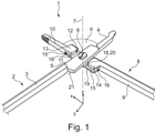
- FIG. 1 shows a medical instrument 1 of a first exemplary embodiment in a perspective view, which comprises a first hand lever 2, which is essentially made up of three sections: a handle section 3, a working section 4 and a bearing section 5.
- the handle section 3 is located at a proximal end of the first hand lever 2 and is used for manual actuation by a user, such as a surgeon or operator or doctor.
- the working section 4 is designed in the manner of a branch and is used to grip, clamp or cut an object, such as tissue of a patient, and is located at a distal end of the first hand lever 2.
- the bearing section 5 which essentially serves to connect the first hand lever 2 by means of a male bearing element 6 to a second hand lever 8 so as to be pivotable about a common axis of rotation 7.
- the second hand lever 8 comprises a handle section 9, a working section 10 and a guide section 11.
- the handle section 9 is located analogously to the handle section 3 of the first hand lever 2, at a proximal end of the second hand lever 8 and the working section 10 is located at a distal end of the second hand lever 8.
- the guide section 11 is arranged between the handle section 9 and the working section 10.
- the guide section 11 has an insertion recess 12 on one side, which enables the bearing section 5 to be inserted in a cleaning or assembly position (as in 1 shown) is easy to assemble and in a working or operating position (see 2 ) by means of two guide projections 13, 14, which are located distally and proximally of the insertion recess 12, at least partially cover the bearing section 5 and thus guide the first hand lever 2 relative to the second hand lever 8.
- the assembly or cleaning position corresponds to a position in which a relative pivoting angle a, measured between the two working sections 4, 10, is selected such that the bearing section 5 is not in engagement with the guide projections 13, 14, or by these is not covered.
- This corresponds to such a relative position of the two hand levers 2 , 8 to one another that the first hand lever 2 can be easily connected to the second hand lever 8 or mounted thereon in the area of the bearing section 5 with the aid of the bearing element 6 .
- a working or operating position of the medical instrument 1, as in 2 shown, describes a position or all positions at a predetermined angle (within an angular range) in which the first hand lever 2 is guided relative to the second hand lever 8 by means of the bearing section 5 through the guide projections 13, 14.
- an object such as human tissue is grasped, clamped or cut.
- the relative pivotability of the two hand levers 2, 8 can be limited by means of a locking mechanism (not shown here), which is provided, for example, on the proximal ends of the respective handle section 3, 9. This can ensure that the operator cannot unintentionally bring the medical instrument 1 into the assembly and cleaning position during operation/use.
- the guide projections 13, 14 have outer edges 15 running on both sides in the longitudinal direction of the second hand lever 8, which are at least one-fifth, preferably one-fourth, as long as the length of the insertion recess 12, as a result of which reliable guidance of the bearing section 5 over the entire operating range is possible .
- the length of the insertion recess 12 is greater than the width of the first hand lever 2 in the area of the bearing element 6. This ensures that the medical instrument 1 can be assembled and disassembled easily.
- the length of the insertion recess 12 is seen in the longitudinal direction of the second hand lever 8 and corresponds to the X-direction of the coordinate system 1 .
- the longitudinal direction of the first hand lever 2 corresponds to 1 the Y-direction and the width of the first hand lever 2 extends in the XY-plane, which corresponds to the pivoting plane of the medical instrument 1, along the X-direction (perpendicular to the Y-direction).
- a thickness of each portion of the first hand lever 2 and the second hand lever 8 extends in the Z direction of the shown coordinate system.
- the thickness of the bearing section 5 is smaller than the height of a guide gap 16, which is formed between an inner surface 17 of the guide projections 13, 14 and a surface of a so-called connecting arm 19 of the guide section 11 that faces it.
- the surface is an inner surface 18 of the connecting arm 19 and serves, in particular in the operating position, as a guiding and contact surface 20 which corresponds to a contact surface 21 (lower surface in 1 ) of the bearing portion 5, these two contact surfaces 20, 21 slidingly touching each other in the operative position.
- the guide projections 13, 14 each have an edge 22 facing the insertion recess 12 (see 2 ) on, which preferably, as e.g. in 1 and 2 shown, convex, crowned or rounded.
- the working sections 4, 10 can, as in 1 and 2 shown, be formed differently, but can alternatively be formed the same.
- the working sections 4, 10, as shown here, are only to be seen as examples and other forms of the working sections 4, 10 are also conceivable.
- 3 and 4 show a second exemplary embodiment of the medical instrument 1.
- This second exemplary embodiment provides that the contact surfaces 20, 21 (see 4 ) now no longer touch, since a spacing-causing element 23 is positioned between them, which spaces the contact surfaces 20, 21 from one another.
- 3 shows the medical instrument 1 of the second exemplary embodiment in the assembly and cleaning position, wherein 3 essentially 1 is equivalent to. The difference between the in 1 shown first exemplary embodiment and in 3 shown second exemplary embodiment is only by the in 4 view shown.
- the bearing element 6 is designed as a screw 24 .
- Alternative embodiments of the bearing element 6 also provide, for example, a rivet.
- connecting elements as a bearing element 6, such as a pin (see also 14 and 15 ), conceivable.
- the space-causing element 23 is designed as a resistance-forming element in the form of a separate ring 25 .
- the spacing-causing element 23 can also be designed as an integrally designed ring, for example in the form of a circumferential collar, or as webs designed on both sides of the bearing element 6 .
- One advantage of the separate component is, among other things, the easy exchangeability of the spacing-causing element 23, which makes it possible to vary the spacing between the guide section 11 and the bearing section 5 by using different spacing-causing elements.
- the spacing-causing element 23 can also, as exemplified in a fourth embodiment (see FIG 8 and 9 ) shown, as a force-applying element, for example.
- a force-applying element In the form of a leaf spring 26 may be formed.
- Such force-applying elements also include other types of springs, such as a plate spring or a spiral spring, and also magnets, in which case the magnetic repulsion is used to space the bearing section 5 and the inner surface 18 of the guide section 11, or alternatively a pressure tank is also possible.
- a thermally active element is also conceivable, which expands, for example, from a certain temperature and thus leads to spacing.
- the Figs. 10 to 13 show a fifth exemplary embodiment of the medical instrument 1, in which a distance-causing element 23 is provided, which enables a targeted manual adjustability of the height (seen along/in the direction of the axis of rotation 7) of the cleaning gap 27.
- a distance-causing element 23 is provided, which enables a targeted manual adjustability of the height (seen along/in the direction of the axis of rotation 7) of the cleaning gap 27.
- 10 shows 10 a top view of the fifth exemplary embodiment of the medical instrument 1 in the assembly and cleaning position, which essentially corresponds to that in 1 and 3 corresponds to the illustrations shown.
- the clearance causing member 23 provided in this embodiment is formed such that on the connecting arm 19 (see FIG 11 ) A spacer sleeve 28 is attached, into which the bearing element 6, which is designed as a screw 24, can be screwed.
- the spacer sleeve 28 has an internal thread in its interior, into which the screw 24 can be screwed/turned.
- a spiral spring 29 in the spacer sleeve 28 which is arranged in a pot 30 formed inside the spacer sleeve 28, the pot 30 having a larger inside diameter than the outside diameter of the internal thread.
- the spiral spring 29 rests with one end on the base/bottom of the pot 30 and with the other end on the outside 31 of the connecting arm 19 .
- the height of the cleaning gap 27 can be specifically adjusted via the screwing depth of the bearing element 6 into the internal thread of the spacer sleeve 28 and the force produced by the prestressing of the spiral spring 29 and acting on the outside 31 of the connecting arm 19 .
- Figs. 5 to 7 as well as the Figs. 14 and 15 show a third and sixth exemplary embodiment, which in each case provides a connection of the hand levers 2, 8 that can be dismantled without tools.
- the third exemplary embodiment shown here provides a bearing 32 in the manner of a bayonet catch 33 (see 7 ).
- the second hand lever 8 has as a guide section 11 a guide section 34 that is essentially circular/round in the XY plane.
- the Leading Section 34 has a guide gap 35 running in the circumferential direction, which is formed by a guide projection 36 running in the circumferential direction, the guide projection 36 extending radially inward from an outer circumference of the guide section 34 .
- the circumferential guide gap 35 or the circumferential guide projection 36 is defined by at least one, preferably several (in figure 5 , four), recesses 37 are interrupted, which are preferably arranged evenly distributed along the circumferential direction.
- the first hand lever 2 shown comprises the handle section 3 and the working section 4, as is already known from the other embodiments.
- the bearing section 5 in the form of a in the XY plane 6
- Substantially circular or round bearing section 38 which is the counterpart to the in figure 5 shown guide portion 34 forms.
- the bearing element 6 is provided integrally in the bearing section 38 and is also referred to below as the bearing element 39 .
- the bearing element 39 is formed in a substantially circular shape in the XY plane, extends along a height direction (Z direction in 6 ) and has a smaller outer diameter than the bearing section 38.
- This circular bearing element 39 has at least one, preferably several, e.g. 2, 3, 4, 5 or 6 (in 6 , Four) projections or projections 40 which extend from an outer circumference of the bearing element 39 radially outwards.
- the number of projections 40 present and their positioning along the circumference corresponds to the number and positioning of the respective recesses 37 on the guide section 34.
- the guide section 34 and the bearing section 38 are matched to one another in such a way that they engage in one another in a form-fitting manner and by relative rotation of the two hand levers 2, 8 a bayonet catch 33 (see 7 ) is realized.
- the operating position extends over the area that is defined by the guide projections 36 . That is, the adjustment angle ⁇ is dependent on the number and positioning of the guide projections 36 and the recesses 37. In FIG Figures 5 to 7 In the exemplary embodiment shown, the adjustment angle ⁇ is, for example, less than 90°. However, if the projections 40 are not evenly distributed (and, as a result, the recesses 37 are also not evenly distributed), a larger adjustment angle ⁇ (for example greater than 90°) can be implemented. Alternatively, it is also conceivable to design the projections 40 in different ways, so that not every projection fits into every recess 37 .
- the projections 40 shown in this embodiment are formed in a trapezoidal shape.
- other geometric shapes such as a pin or a triangular shape, etc., are also conceivable which, in combination with the correspondingly designed recesses 37 on the guide section 34, enable the two hand levers 2, 8 to be connected in the manner of a bayonet catch.
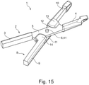
- 14 and 15 show a sixth exemplary embodiment, which essentially corresponds to that in 1 and 2 corresponds to the first embodiment shown, with the difference that only a pin 41 is provided as a bearing element 6 .
- This is here formed integrally with the second hand lever 8 and is pushed through or inserted through a hole 42 during assembly of the medical instrument 1 in the assembly and cleaning position, which is located in the bearing section 5 of the first hand lever 2 .
- the two hand levers 2, 8 are moved by means of the guide projections 13, 14 (see 15 ) relative to each other.
- the two hand levers 2, 8 can be separated from one another without tools, which corresponds to a tool-free disassembly of the medical instrument 1, e.g. for cleaning and sterilization.
- the bearing element 6 can also be provided as a separately formed pin, for example in the form of a threaded pin, which can then be screwed into a thread provided on the guide section 11 .
Landscapes
- Health & Medical Sciences (AREA)
- Life Sciences & Earth Sciences (AREA)
- Engineering & Computer Science (AREA)
- Surgery (AREA)
- Medical Informatics (AREA)
- Nuclear Medicine, Radiotherapy & Molecular Imaging (AREA)
- Biomedical Technology (AREA)
- Heart & Thoracic Surgery (AREA)
- Ophthalmology & Optometry (AREA)
- Molecular Biology (AREA)
- Animal Behavior & Ethology (AREA)
- General Health & Medical Sciences (AREA)
- Public Health (AREA)
- Veterinary Medicine (AREA)
- Mechanical Engineering (AREA)
- Surgical Instruments (AREA)
- Dental Tools And Instruments Or Auxiliary Dental Instruments (AREA)
Description
- Die vorliegende Erfindung betrifft ein medizinisches Instrument, wie bspw. eine Klemme, eine Zange oder ein anderes scherenartiges Handwerkzeug, mit einem ersten Handhebel, der einen zum Betätigen per Hand vorgesehenen Handgriffabschnitt an seinem proximalen Ende, einen Arbeitsabschnitt, etwa nach Art einer Branche, zum Greifen, Klemmen oder Schneiden eines Objekts an seinem distalen Ende und einen dazwischenliegenden Lagerabschnitt aufweist, an dem ein Lagerelement angreift, um eine Schwenkbarkeit um eine Drehachse zwischen dem ersten Handhebel und einem zweiten Handhebel zu ermöglichen, wobei der zweite Handhebel einen Handgriffabschnitt an seinem proximalen Ende, einen Arbeitsabschnitt an seinem distalen Ende und einen dazwischenliegenden Führungsabschnitt aufweist, an dem das Lagerelement angreift, wobei eine Lagerung derart ausgebildet ist, dass die beiden Handhebel in der Betriebsstellung mittels des Lagerelements formschlüssig, jedoch zueinander verschwenkbar gelagert sind und dass die Handhebel in einer Reinigungsstellung werkzeuglos demontierbar sind, wobei in dem Lagerabschnitt des ersten Handhebels das männliche Lagerelement integral vorgesehen ist und wobei der Führungsabschnitt des zweiten Handhebels im Wesentlichen rund ausgebildet ist, d.h., in der Schwenkebene (die Ebene senkrecht zur Drehachse) kreisförmig ausgebildet ist und einen am Außenumfang des Führungsabschnitts ausgebildeten, in Umfangsrichtung verlaufenden Führungsspalt aufweist.
- Aus der
DE 20 2013 010 321 U1 ist ein zangenartiges medizinisches Instrument bekannt, welches aus einem ersten, eine Führungsplatte aufweisenden Handhebel und einem zweiten, eine Lagerplatte aufweisenden Handhebel besteht, welche über einen im Bereich der Führungsplatte und der Lagerplatte angeordneten und mit einem radial erweiterten Kopfteil versehenen Lagerzapfen schwenkbar miteinander verbunden sind, wobei die Lagerplatte in ihren längsseitigen Randbereichen jeweils eine Aufnahmenut bildet, in welche die Führungsplatte in ihrer Betriebsstellung eingreift, wobei die Lagerplatte zwischen den Aufnahmenuten eine sich über die komplette Breite der Lagerplatte erstreckende Vertiefung aufweist und die Führungsplatte aus ihrer Betriebsstellung in eine Reinigungsstellung relativ zur Lagerplatte drehbar ist, in welcher die Führungsplatte mit der Vertiefung in Überdeckung gelangt und im Bereich der Vertiefung zwischen der Führungsplatte und der Lagerplatte ein Distanzelement vorgesehen ist, dessen Höhe in Richtung des Lagerzapfens gleich groß oder kleiner ist als die Tiefe der Vertiefung. - Die
DE 20 2010 010 843 U1 offenbart ein scherenartiges oder zangenartiges medizinisches Handwerkzeug mit zwei jeweils zweiarmigen Handhebeln, die im Bereich zweier plattenartig abgeflachter Mittelabschnitte durch einen Gelenkzapfen gelenkig miteinander verbunden und gegeneinander verschwenkbar sind, wobei jeweils ein vorzugsweise kurzer Hebelarm jedes Handhebels als Werkzeug ausgebildet ist und der jeweils zweite, längere Hebelarm als Handgriff ausgebildet ist, wobei der im abgeflachten Mittelabschnitt des einen Handhebels unbeweglich befestigte Gelenkzapfen mit einem Ringflansch versehen ist, der von dem Mittelabschnitt des ersten Handhebels, in dem der Gelenkzapfen befestigt ist, einen Abstand aufweist, der mindestens der doppelten Dicke des auf dem Gelenkzapfen gelagerten Mittelabschnitts des zweiten Handhebels entspricht, sodass der zweite Handhebel in der maximalen Schwenklage der beiden Handhebel auf dem Gelenkzapfen wenigstens so weit in eine Lage verschiebbar ist, in welcher auch die einander gegenüber liegenden Innenflächen der abgeflachten Mittelabschnitte und der Gelenkzapfen frei liegen. - Die
DE 20 2011 107 977 U1 wiederum offenbart ein scherenartiges oder zangenartiges medizinisches Instrument mit einem ersten und einem zweiten Handhebel, welche jeweils ein Griffteil und ein Werkzeugteil aufweisen und welche über einen mit einem radial erweiterten Kopfteil versehenen Lagerzapfen schwenkbar miteinander in Verbindung stehen, wobei der erste Handhebel im Bereich zwischen seinem Griffteil und seinem Werkzeugteil eine Führungsplatte bildet und der zweite Handhebel im Bereich zwischen seinem Griffteil und seinem Werkzeugteil eine Lagerplatte bildet, in deren Bereich der Lagerzapfen feststehend angeordnet ist, wobei die Führungsplatte zur schwenkbaren Aufnahme des Lagerzapfens einen Durchbruch aufweist und wobei sich die Führungsplatte und die Lagerplatte im normalen Betriebszustand des Instruments flächig berühren, wobei der Durchbruch der Führungsplatte als ein sich in Längsrichtung der Führungsplatte erstreckendes Langloch ausgebildet ist und das Langloch im Randbereich seines dem Werkzeugteil benachbarten Endbereichs eine erste erweiterte Vertiefung und im Randbereich seines in Längsrichtung gegenüberliegenden Endbereichs eine zweite erweiterte Vertiefung aufweist, in welchen das Kopfteil des Lagerzapfens wahlweise aufnehmbar ist und die erste Vertiefung eine geringere Tiefe aufweist als die zweite Vertiefung und die Lagerplatte auf ihrer der Führungsplatte zugewandten Kontaktfläche eine im Bereich des Lagerzapfens angeordnete, quer zur Lagerplatte verlaufende Quernut aufweist, deren Tiefe zumindest der Tiefe der ersten Vertiefung des Langlochs entspricht und deren Breite zumindest der Breite der Führungsplatte entspricht und wobei der erste Handhebel mit seiner Führungsplatte in einer mit der Quernut fluchtende Schwenkposition bringbar und in Richtung des Lagerzapfens in die Quernut so weit verstellbar ist, dass das Kopfteil des Lagerzapfens mit der ersten Vertiefung des Langlochs außer Eingriff gelangt und das Kopfteil des Lagerzapfens durch eine Verstellung des zweiten Handhebels mit seiner Lagerplatte und dem Lagerzapfen entlang des Langlochs mit der zweiten Vertiefung des Langlochs in Überdeckung und durch eine Verstellung in Richtung des Lagerzapfens mit der zweiten Vertiefung in Eingriff bringbar ist und die Führungsplatte und die Lagerplatte in dieser Position einen Abstand voneinander aufweisen. - Die
DE 20 2009 002 367 U1 offenbart ein medizinisches Instrument, insbesondere eine Zange, aus zwei Hälften, die über einen ersten und einen zweiten Schluss miteinander verbunden sind, wobei der zweite Schluss zumindest eine Führungsrinne für zumindest eine Drehfläche des ersten Schlusses aufweist, wobei die Führungsrinne nur teilweise durch einen Boden begrenzt ist. - Weiterer, ähnlicher Stand der Technik ist aus den Druckschriften
GB 2 280 397 A US 2005/0186536 A1 undUS 5,232,360 bekannt. - Benachbarter Stand der Technik ist auch aus den Druckschriften
DE 10 2008 058 207 A1 ,DE 86128 A undDE 836548 B bekannt. Auch ist der Artikel von R. Ulrich "Über die Entwicklung zerlegbarer Klemmen- und Zangenschlüsse" aus "Die Medizinmechanik", vol. 58, 1937, Nr. 24, S. 239-242 bekannt. - Bei den aus dem Stand der Technik bekannten medizinischen Instrumenten sind die Führungsbereiche jedoch sehr minimal ausgebildet, sodass eine exakte und präzise Führung der beiden Handhebel zueinander nicht immer gewährleistet ist. Bei manchen der bekannten medizinischen Instrumente ist darüber hinaus die Montage bzw. Demontage des medizinischen Instruments mit größerem Aufwand verbunden. Andere wiederum benutzen eine bajonettartige Verbindung, um die beiden Handhebel miteinander zu verbinden. Diese sind in der Regel jedoch sehr aufwändig zu reinigen, da sie viele Verwinkelungen und/oder Hinterschnitte aufweisen, in denen sich zum einen im Betrieb leicht Flüssigkeit ansammelt und zum anderen bei der Reinigung die Reinigungsflüssigkeit ansammelt.
- Aufgabe der Erfindung ist es, die Nachteile aus dem Stand der Technik zu vermeiden oder wenigstens zu mildern, und insbesondere eine werkzeuglos demontierbare/lösbare Verschlussverbindung der beiden Handhebel vorzusehen, welche möglichst leicht zu reinigen ist.
- Die Aufgabe der Erfindung wird bei einem gattungsgemäßen medizinischen Instrument dadurch gelöst, dass der umlaufende Führungsspalt durch mehrere in Umfangsrichtung verteilte Ausnehmungen unterbrochen ist.
- Das vereinfacht zum einen die Montage, reduziert zum anderen die Gesamtkomponentenzahl und ermöglicht eine einfache Reinigung.
- Vorteilhafte Ausführungsformen sind in den Unteransprüchen beansprucht und werden nachfolgend erläutert.
- So ist es von Vorteil, wenn die Lagerung nach Art eines Bajonettverschlusses ausgebildet ist. Dadurch ist sowohl eine werkzeuglose Montage wie auch Demontage möglich. Der Bereich, in dem der Bajonettverschluss geschlossen ist, d.h., die beiden Handhebel miteinander in Formschluss sind, entspricht hierbei der Betriebsstellung.
- Ferner ist es von Vorteil, wenn das Lagerelement im Wesentlichen rund, d.h. in der Schwenkebene (die Ebene senkrecht zur Drehachse) kreisförmig ausgebildet ist und in Umfangsrichtung vorzugsweise gleichverteilte, bspw. 2, 3, 4, 5 oder 6 Vorsprünge / Überstände aufweist. Diese dienen der formschlüssigen Verbindung nach Art eines Bajonettverschlusses des ersten Handhebels mit dem zweiten Handhebel.
- Hierfür ist es von Vorteil, wenn die Vorsprünge trapezförmig ausgebildet sind.
- Eine vorteilhafte Ausführungsform sieht vor, dass die trapezformartigen Vorsprünge radial außen eine längere Seitenkante aufweisen als radial innen.
Hierbei ist es von Vorteil, wenn die Anzahl und die Position entlang des Umfangs der jeweiligen Vorsprünge / Überstände der Anzahl und der Position entlang des Umfangs der jeweiligen Ausnehmungen entspricht. Nur so ist eine einfach Montage bzw. Demontage des medizinischen Instruments möglich. Eine vorteilhafte Ausführungsform sieht hierbei vor, dass insgesamt vier Ausnehmungen vorgesehen sind, welche über den Umfang gleichverteilt angeordnet sind. - Andere vorteilhafte Ausführungsformen der Vorsprünge / Überstände sehen vor, dass diese zapfenartig ausgebildet sind. Jedoch sind auch jegliche andere geometrische Formen denkbar.
- Für die relative Verschwenkbarkeit der beiden Handhebel zueinander ist es von Vorteil, wenn diese durch einen Rastmechanismus begrenzt ist, welcher vorzugsweise an dem proximalen Ende des jeweiligen Handgriffabschnitts angeordnet / vorgesehen ist. Somit kann verhindert werden, dass während einer Nutzung durch einen Bediener, wie bspw. ein Arzt, ein Operateur oder ein anderer Bediener, das medizinische Instrument versehentlich in die Reinigungsstellung gebracht wird.
- Eine weitere mögliche Ausführungsform sieht vor, dass die Arbeitsabschnitte des ersten Handhebels und des zweiten Handhebels gleich oder unterschiedlich (zueinander) ausgebildet sind. Dies ist abhängig davon, zu welchem Zweck das medizinische Instrument eingesetzt werden soll.
- Für die sichere Bedienung / Benutzung des medizinischen Instruments hat es sich als vorteilhaft erwiesen, wenn die Handgriffabschnitte ergonomisch geformt sind. Unter einer ergonomischen Form wird hierbei verstanden, dass die Handgriffabschnitte eine solche Form aufweisen, dass sie ein Greifen, Halten und Bedienen des medizinisches Instruments mittels einer Hand eines Bedieners für diesen vereinfachen, bzw. angenehmer gestalten und dadurch ein leichteres und längeres Bedienen des medizinischen Instruments möglich ist, verglichen mit einer nicht ergonomischen Form, wie bspw., wenn die Handgriffabschnitte einfach nach Art einer Stange, ohne Krümmung und mit konstanter Dicke, ausgebildet sind. Ergonomische Formen können bspw. Krümmungen und/oder Vertiefungen umfassen, welche der Form/Kontur einer Hand und/oder Fingern nachempfunden sind, wenn diese das medizinische Instrument greifen/halten/bedienen.
- Ferner ist es von Vorteil, wenn die relative Verschwenkung der beiden Handhebel zueinander in der Betriebsstellung durch die Anzahl und Positionierung der über den Umfang verteilten Ausnehmungen definiert ist.
- Alternativ ist es auch denkbar, dass die Erfindung zusätzlich oder stattdessen einen, mehrere oder alle nachfolgenden Aspekte umfasst. Diese Aspekte können in einer oder mehreren Teilanmeldungen auch ohne die Merkmale des unabhängigen Anspruchs weiterverfolgt werden.
- Ein solcher Aspekt betrifft bspw. ein medizinisches Instrument, mit einem ersten Handhebel, der einen zum Betätigen per Hand vorgesehenen Handgriffabschnitt an seinem proximalen Ende, einen Arbeitsabschnitt zum Greifen, Klemmen oder Schneiden eines Objekts an seinem distalen Ende und einen dazwischenliegenden Lagerabschnitt aufweist, an dem ein Lagerelement angreift, um eine Schwenkbarkeit um eine Drehachse zwischen dem ersten Handhebel und einem zweiten Handhebel zu ermöglichen, wobei der zweite Handhebel einen Handgriffabschnitt an seinem proximalen Ende, einen Arbeitsabschnitt an seinem distalen Ende und einen dazwischenliegenden Führungsabschnitt aufweist, an dem das Lagerelement angreift, wobei der Führungsabschnitt des zweiten Handhebels auf einer Seite eine Einlegeausnehmung besitzt, um den Lagerabschnitt des ersten Handhebels so aufzunehmen, dass zwei Führungsüberstände distal und proximal der Einlegeausnehmung in einer Betriebsstellung, in der ein Greifen, Klemmen oder Schneiden stattfindet, den Lagerabschnitt wenigstens abschnittsweise überdecken, wobei in Längsrichtung verlaufende Außenkanten beider Führungsüberstände wenigstens ein Fünftel so lang sind wie die Länge der Einlegeausnehmung und die Länge der Einlegeausnehmung größer ist als die Breite des ersten Handhebels im Bereich des Lagerelements.
- Dabei ist es von Vorteil, wenn die Dicke des Lagerabschnitts kleiner ist als die Höhe eines zwischen einer Innenoberfläche der Führungsüberstände und der ihr zugewandten Innenoberfläche eines Verbindungsarms des Führungsabschnitts ausgebildeten Führungsspalts. Dadurch wird der Lagerabschnitt innerhalb dieses Führungsspalts präzise geführt und die damit einhergehende Relativbewegung der beiden Handhebel in der Betriebsstellung ist exakt ausführbar.
- Hierbei hat es sich als vorteilhaft herausgestellt, wenn das Lagerelement form-, kraft- oder stoffschlüssig mit dem zweiten Handhebel verbunden ist, etwa befestigt ist. Hierbei kann das Lagerelement bspw. als eine Schraube oder als ein Niet ausgebildet sein, wobei eine Schraube im Gegensatz zu einem Niet einfacher (und zerstörungsfrei) demontierbar ist, wohingegen ein Niet sich nicht unbeabsichtigt lösen kann.
- Eine vorteilhafte Ausführungsform der Erfindung sieht vor, dass der Lagerabschnitt, etwa in der jeweiligen Mitte, eine geringere Dicke aufweist als der Handgriffabschnitt und/oder der Arbeitsabschnitt, etwa in deren jeweiliger Mitte. Dies macht insbesondere fertigungstechnisch gesehen Sinn, da so das Rohteil des medizinischen Instruments mit einer konstanten Dicke hergestellt werden kann und der Lagerabschnitt in einem anschließenden Schritt bspw. mittels Fräsen oder einem anderen materialabtragenden Verfahren auf die gewünschte Dicke gebracht werden kann, wobei optional (abhängig von dem gewählten Verfahren) gleichzeitig die für die Führung in den Führungsspalten notwendige Oberflächenbeschaffenheit erzeugt werden kann.
- Weiter ist es von Vorteil, wenn die Schwenkbarkeit um die Drehachse einen relativen Verschwenkwinkel zwischen den Arbeitsabschnitten von 0° bis größer 90°, vorzugsweise bis 120°, zulässt. Dadurch ist es möglich, das medizinische Instrument auch in eine zur Reinigung und Sterilisation des medizinischen Instruments vorgesehene Reinigungsstellung zu bringen. Die Reinigungsstellung entspricht hierbei vorzugsweise einer Montagestellung, in der die beiden Handhebel mithilfe des Lagerelements verschwenkbar zueinander verbunden werden.
- Alternativ kann es von Vorteil sein, wenn der Lagerabschnitt und der Führungsabschnitt einander zugewandte Kontaktflächen aufweisen, die über ein separates oder integrales Abstandverursachungselement zueinander beabstandet sind, so dass sich die Kontaktflächen auch in der Betriebsstellung nicht mehr gleitend berühren. Dadurch wird insbesondere der Reinigungs- und Sterilisationsvorgang des medizinischen Instruments vereinfacht.
- Hierbei hat es sich als vorteilhaft herausgestellt, wenn das Abstandverursachungselement als ein separater Ring oder als ein integral ausgebildeter, umlaufender Bund ausgebildet ist oder integral ausgebildete und beidseitig des Lagerelements einander gegenüberliegend ausgebildete Stege besitzt.
- Eine weitere vorteilhafte Ausführungsform sieht vor, dass das Abstandverursachungselement als eine Feder, ein Magnet oder ein Druckbehälter ausgebildet ist oder ein thermoaktives Element besitzt. Hierbei wird der Abstand zwischen dem Führungsabschnitt und dem Lagerabschnitt ausgebildet, indem das Abstandverursachungselement eine Kraft aufbringt, welche den Lagerabschnitt von dem Führungsabschnitt beabstandet.
- Für das medizinische Instrument ist es von Vorteil, wenn die Handhebel sowohl in die Betriebsstellung als auch in eine Reinigungsstellung bringbar sind. Die Reinigungsstellung entspricht hierbei vorteilhafterweise der Montagestellung, in der die zwei Handhebel mittels des Lagerelements miteinander verbunden werden.
- Darüber hinaus ist es von Vorteil, wenn die Führungsüberstände zusammen mit der Kontaktfläche des Führungsabschnitts des zweiten Handhebels einen Hinterschnitt, bspw. in Form einer Führungsnut, ausbilden.
- Weiter ist es von Vorteil, wenn die beiden Führungsüberstände jeweils eine Dicke besitzen, die zwischen ca. 80 % und ca. 120 % der Dicke des in der Einlegeausnehmung aufzunehmenden Lagerabschnitts entspricht, vorzugsweise (exakt) 100 %. Dadurch kann sichergestellt werden, dass die Führungsüberstände eine ausreichend hohe Stabilität aufweisen, um den Lagerabschnitt entsprechend präzise zu führen.
- Eine weitere vorteilhafte Ausführungsform sieht vor, dass die Führungsüberstände beidseitig der Einlegeausnehmung einander zugewandte Kanten / Ränder besitzen, die konvex oder ballig oder abgerundet ausgeformt sind. Dadurch werden scharfe Kanten, Ecken (z.B. durch einen überstehenden Grat) verhindert und somit das Verletzungsrisiko für den Bediener sowie für den Patienten reduziert.
- Für die Führung des Lagerabschnitts ist es von Vorteil, wenn der proximale Führungsüberstand eine proximale Endkante besitzt, die parallel zu einer proximalen Endkante des Verbindungsarms und senkrecht zu der Längsachse des zweiten Handhebels ausgerichtet ist.
- Aus den gleichen Gründen ist es von Vorteil, wenn der distale Führungsüberstand eine distale Endkante besitzt, die parallel zu einer distalen Endkante des Verbindungsarms und senkrecht zu der Längsachse des zweiten Handhebels ausgerichtet ist.
- Hierbei hat es sich als vorteilhaft herausgestellt, wenn der Flächenträgheitsschwerpunkt des Führungsüberstands auf der in Längsrichtung verlaufenden Symmetrieachse liegt. Dadurch ist eine gute Bedienbarkeit des medizinischen Instruments möglich.
- Ein anderer Aspekt betrifft ein medizinisches Instrument, mit einem ersten Handhebel, der einen zum Betätigen per Hand vorgesehenen Handgriffabschnitt an seinem proximalen Ende, einen Arbeitsabschnitt zum Greifen, Klemmen oder Schneiden eines Objekts an seinem distalen Ende und einen dazwischenliegenden Lagerabschnitt aufweist, an dem ein Lagerelement angreift, um eine Schwenkbarkeit um eine Drehachse zwischen dem ersten Handhebel und einem zweiten Handhebel zu ermöglichen, wobei der zweite Handhebel einen Handgriffabschnitt an seinem proximalen Ende, einen Arbeitsabschnitt an seinem distalen Ende und einen dazwischenliegenden Führungsabschnitt aufweist, an dem das Lagerelement angreift, wobei der Führungsabschnitt des zweiten Handhebels auf einer Seite eine Einlegeausnehmung besitzt, um den Lagerabschnitt des ersten Handhebels so aufzunehmen, dass zwei Führungsüberstände distal und proximal der Einlegeausnehmung in einer Betriebsstellung, in der ein Greifen, Klemmen oder Schneiden stattfindet, den Lagerabschnitt wenigstens abschnittsweise überdecken, wobei der Lagerabschnitt des ersten Handhebels durch ein für eine Beabstandung Kraft oder Widerstand zur Verfügung stellendes Abstandverursachungselement so in der Betriebsstellung von dem Führungsabschnitt des zweiten Handhebels weggedrückt wird, dass sich ein Reinigungsspalt zwischen dem ersten Handhebel und dem zweiten Handhebel bis in den Bereich unter den Führungsüberständen auf der führungsüberstandabgewandten Seite des ersten Handhebels erstreckt.
- Hierbei ist es beispielsweise von Vorteil, wenn das Abstandverursachungselement derart ausgebildet ist, dass eine Reinigungsspalthöhe gezielt manuell einstellbar ist. Ein solches Abstandverursachungselement ermöglicht es dem Benutzer des medizinischen Instruments die Reinigungsspalthöhe variabel individuell anpassen zu können.
- Ferner vorteilhaft ist es, wenn die Reinigungsspalthöhe in der Betriebsstellung kleiner ist als die Reinigungsspalthöhe in einer Reinigungsstellung. Durch eine vergrößerte Spalthöhe in der Reinigungsstellung wird somit die Reinigung und Sterilisation des medizinischen Instruments weiter vereinfacht.
- Hierbei ist es von Vorteil, wenn die Reinigungsstellung einer Montagestellung der beiden Handhebel entspricht. So kann das medizinische Instrument zur Reinigung und/oder Sterilisation bei Bedarf auch demontiert werden.
- Eine andere beispielhafte Ausführungsform sieht vor, dass der Lagerabschnitt des ersten Handhebels die Führungsüberstände in einer Betriebsstellung gleitend berührt / kontaktiert und somit präzise geführt wird.
- Hierbei hat es sich als vorteilhaft herausgestellt, wenn eine Dicke des Lagerabschnitts kleiner ist als eine Höhe eines durch den jeweiligen Führungsüberstand ausgebildeten Führungsspalts.
- Mit anderen Worten besteht die Erfindung darin, dass ein medizinisches Instrument bereitgestellt wird, welches ohne Verschlussniet bzw. Verschlussschraube mittels einer werkzeuglos demontierbaren Verbindungsvariante zusammengesetzt ist.
- Die Erfindung wird nachfolgend mit Hilfe von
Figuren 5-7 näher erläutert. - Die Figuren zeigen:
- Fig. 1
- eine perspektivische Ansicht eines medizinischen Instruments einer ersten beispielhaften Ausführungsform in einer Montage- bzw. Reinigungsstellung;
- Fig. 2
- eine perspektivische Ansicht des medizinischen Instruments der ersten beispielhaften Ausführungsform in einer Arbeits- bzw. Betriebsstellung;
- Fig. 3
- eine Draufsicht einer zweiten beispielhaften Ausführungsform des medizinischen Instruments in der Montage- bzw. Reinigungsstellung;
- Fig. 4
- eine Ansicht von oben der zweiten beispielhaften Ausführungsform, in Richtung des Pfeils IV aus
Fig. 3 gesehen; - Fig. 5
- eine perspektivische Ansicht eines zweiten Handhebels des medizinischen Instruments einer dritten beispielhaften Ausführungsform;
- Fig. 6
- eine perspektivische Ansicht eines ersten Handhebels des medizinischen Instruments der dritten Ausführungsform;
- Fig. 7
- eine perspektivische Ansicht des ersten Handhebels und des zweiten Handhebels des medizinischen Instruments in der dritten beispielhaften Ausführungsform in einer montierten Position;
- Fig. 8
- eine perspektivische Draufsicht des medizinischen Instruments in einer vierten beispielhaften Ausführungsform in der Montage- bzw. Reinigungsstellung;
- Fig. 9
- eine Draufsicht, entlang des Pfeils IX aus
Fig. 8 gesehen, des medizinischen Instruments in der vierten beispielhaften Ausführungsform; - Fig. 10
- eine Draufsicht des medizinischen Instruments in einer fünften beispielhaften Ausführungsform;
- Fig. 11
- eine Seitenansicht des medizinischen Instruments der fünften beispielhaften Ausführungsform;
- Fig. 12
- eine ausschnittsweise, vergrößert dargestellte Ansicht des medizinischen Instruments der fünften Ausführungsform im Bereich der Verbindungsstelle des ersten Handhebels und des zweiten Handhebels in einer ersten Position;
- Fig. 13
- eine Detailansicht des Lagerelements in einer zweiten möglichen Position;
- Fig. 14
- eine perspektivische Ansicht des medizinischen Instruments in einer sechsten beispielhaften Ausführungsform in einem demontierten Zustand; und
- Fig. 15
- eine perspektivische Ansicht des medizinischen Instruments der sechsten beispielhaften Ausführungsform in der Betriebsstellung.
- Die Figuren sind lediglich schematischer Natur und dienen nur dem Verständnis der Erfindung. Die gleichen Elemente sind mit denselben Bezugszeichen versehen.
- Merkmale der einzelnen Ausführungsbeispiele können auch in anderen Ausführungsbeispielen realisiert werden. Sie sind also untereinander austauschbar.
-
Fig. 1 zeigt ein medizinisches Instrument 1 einer ersten beispielhaften Ausführungsform in einer perspektivischen Ansicht, das einen ersten Handhebel 2 umfasst, welcher im Wesentlichen aus drei Abschnitten aufgebaut ist: einem Handgriffabschnitt 3, einem Arbeitsabschnitt 4 und einem Lagerabschnitt 5. - Der Handgriffabschnitt 3 befindet sich an einem proximalen Ende des ersten Handhebels 2 und dient einem Betätigen per Hand durch einen Nutzer, wie bspw. einem Chirurgen bzw. Operateur oder Arzt. Der Arbeitsabschnitt 4 ist etwa nach Art einer Branche ausgebildet, und dient dem Greifen, Klemmen oder Schneiden eines Objekts, wie bspw. Gewebe eines Patienten, und befindet sich an einem distalen Ende des ersten Handhebels 2. Zwischen dem Handgriffabschnitt 3 und dem Arbeitsabschnitt 4 befindet sich der Lagerabschnitt 5, welcher im Wesentlichen dazu dient, den ersten Handhebel 2 mittels eines männlichen Lagerelements 6 mit einem zweiten Handhebel 8 um eine gemeinsame Drehachse 7 verschwenkbar zu verbinden.
- Der zweite Handhebel 8 umfasst einen Handgriffabschnitt 9, einen Arbeitsabschnitt 10 und einen Führungsabschnitt 11. Der Handgriffabschnitt 9 befindet sich analog zum Handgriffabschnitt 3 des ersten Handhebels 2, an einem proximalen Ende des zweiten Handhebels 8 und der Arbeitsabschnitt 10 befindet sich an einem distalen Ende des zweiten Handhebels 8. Zwischen dem Handgriffabschnitt 9 und dem Arbeitsabschnitt 10 ist der Führungsabschnitt 11 angeordnet.
- Der Führungsabschnitt 11 besitzt auf einer Seite eine Einlegeausnehmung 12, welche es ermöglicht, dass der Lagerabschnitt 5 in einer Reinigungs- bzw. Montagestellung (wie in
Fig. 1 gezeigt) einfach montierbar ist und in einer Arbeits- bzw. Betriebsstellung (sieheFig. 2 ) mittels zweier Führungsüberstände 13, 14, welche sich distal und proximal der Einlegeausnehmung 12 befinden, den Lagerabschnitt 5 wenigstens abschnittsweise überdecken und somit den ersten Handhebel 2 gegenüber dem zweiten Handhebel 8 führen. - Die Montage- bzw. Reinigungsstellung entspricht einer solchen Stellung, in der ein relativer Verschwenkwinkel a, zwischen den zwei Arbeitsabschnitten 4, 10 gemessen, so gewählt ist, dass der Lagerabschnitt 5 nicht mit den Führungsüberständen 13, 14 in Eingriff ist, bzw. von diesen nicht überdeckt wird. Dies entspricht einer solchen relativen Stellung der beiden Handhebel 2, 8 zueinander, dass der erste Handhebel 2 im Bereich des Lagerabschnitts 5 mit Hilfe des Lagerelements 6 einfach mit dem zweiten Handhebel 8 verbunden bzw. daran montiert werden kann.
- Eine Arbeits- bzw. Betriebsstellung des medizinischen Instruments 1, wie in
Fig. 2 gezeigt, beschreibt eine Stellung bzw. sämtliche Stellungen in einem vorgegebenen Winkel (innerhalb eines Winkelbereichs), in dem der erste Handhebel 2 mittels des Lagerabschnitts 5 durch die Führungsüberstände 13, 14 relativ zum zweiten Handhebel 8 geführt wird. In der Betriebsstellung findet ein Greifen, Klemmen oder Schneiden eines Objekts, wie bspw. menschliches Gewebe, statt. - Die relative Verschwenkbarkeit der beiden Handhebel 2, 8 kann mittels eines Rastmechanismus (hier nicht gezeigt) begrenzt sein, welcher bspw. an den proximalen Enden des jeweiligen Handgriffabschnitts 3, 9 vorgesehen ist. Dadurch kann sichergestellt werden, dass der Bediener das medizinische Instrument 1 während der Bedienung / Nutzung nicht unbeabsichtigt in die Montage- und Reinigungsstellung bringen kann.
- Die Führungsüberstände 13, 14 weisen beidseitig in Längsrichtung des zweiten Handhebels 8 verlaufende Außenkanten 15 auf, die wenigstens ein Fünftel, vorzugsweise ein Viertel, so lang sind wie eine Länge der Einlegeausnehmung 12, wodurch eine sichere Führung des Lagerabschnitts 5 über den gesamten Betriebsbereich möglich ist.
- Die Länge der Einlegeausnehmung 12 ist hierbei größer als die Breite des ersten Handhebels 2 im Bereich des Lagerelements 6. Dadurch ist gewährleistet, dass eine einfache Montage bzw. Demontage des medizinischen Instruments 1 möglich ist.
- Die Länge der Einlegeausnehmung 12 wird hierbei in Längsrichtung des zweiten Handhebels 8 gesehen und entspricht der X-Richtung des Koordinatensystems aus
Fig. 1 . Die Längsrichtung des ersten Handhebels 2 entspricht inFig. 1 der Y-Richtung und die Breite des ersten Handhebels 2 erstreckt sich in der XY-Ebene, welches der Schwenkebene des medizinischen Instruments 1 entspricht, entlang der X-Richtung (senkrecht zur Y-Richtung). Eine Dicke jeglicher Abschnitte des ersten Handhebels 2 und des zweiten Handhebels 8 erstreckt sich in Z-Richtung des gezeigten Koordinatensystems. - Sowohl aus
Fig. 1 , insbesondere jedoch ausFig. 2 , ist gut erkennbar zu entnehmen, dass die Dicke des Lagerabschnitts 5 kleiner ist als die Höhe eines Führungsspalts 16, welcher zwischen einer Innenoberfläche 17 der Führungsüberstände 13, 14 und einer ihrer zugewandten Oberfläche eines so genannten Verbindungsarms 19 des Führungsabschnitts 11 ausgebildet ist. Die Oberfläche ist eine Innenoberfläche 18 des Verbindungsarms 19 und dient insbesondere in der Betriebsstellung als Führungs-und Kontaktoberfläche 20, die einer Kontaktoberfläche 21 (untere Oberfläche inFig. 1 ) des Lagerabschnitts 5 zugewandt ist, wobei diese beiden Kontaktoberflächen 20, 21 in der Betriebsstellung einander gleitend berühren. - Die Führungsüberstände 13, 14 weisen jeweils eine der Einlegeausnehmung 12 zugewandte Kante 22 (siehe
Fig. 2 ) auf, die vorzugsweise, wie u.a. inFig. 1 undFig. 2 gezeigt, konvex, ballig oder abgerundet ausgeformt ist. - Die Arbeitsabschnitte 4, 10 können, wie in
Fig. 1 undFig. 2 gezeigt, unterschiedlich ausgebildet sein, können jedoch alternativ auch gleich ausgebildet sein. Die Arbeitsabschnitte 4, 10, wie hier gezeigt, sind lediglich beispielhaft zu sehen und es sind auch andere Ausprägungen der Arbeitsabschnitte 4, 10 denkbar. -
Fig. 3 und Fig. 4 zeigen eine zweite beispielhafte Ausführungsform des medizinischen Instruments 1. Diese zweite beispielhafte Ausführungsform sieht vor, dass sich die Kontaktoberflächen 20, 21 (sieheFig. 4 ) nun nicht mehr berühren, da zwischen ihnen ein Abstandverursachungselement 23 positioniert ist, welches die Kontaktoberflächen 20, 21 zueinander beabstandet.Fig. 3 zeigt das medizinische Instrument 1 der zweiten beispielhaften Ausführungsform in der Montage- und Reinigungsstellung, wobeiFig. 3 im WesentlichenFig. 1 entspricht. Der Unterschied zwischen der inFig. 1 gezeigten ersten beispielhaften Ausführungsform und der inFig. 3 gezeigten zweiten beispielhaften Ausführungsform wird erst durch die inFig. 4 gezeigte Ansicht ersichtlich. - In der zweiten beispielhaften Ausführungsform, wie auch schon in der ersten gezeigten beispielhaften Ausführungsform ist das Lagerelement 6 als eine Schraube 24 ausgebildet. Alternative Ausführungsformen des Lagerelements 6 sehen bspw. auch ein Niet vor. Es sind jedoch auch weitere Verbindungselemente als Lagerelement 6, wie bspw. ein Zapfen (siehe hierzu auch
Fig. 14 undFig. 15 ), denkbar. - In
Fig. 4 ist das Abstandverursachungselement 23 als ein widerstandbildendes Element in Form eines separaten Rings 25 ausgebildet. Alternativ kann das Abstandverursachungselement 23 auch als ein integral ausgebildeter Ring, bspw. in Form eines umlaufenden Bundes oder als beidseitig des Lagerelements 6 ausgebildete Stege ausgebildet sein. Ein Vorteil des separaten Bauteils ist u.a. die leichte Austauschbarkeit des Abstandverursachungselements 23, welche es ermöglicht, mithilfe der Verwendung verschiedener Abstandverursachungselemente den Abstand zwischen dem Führungsabschnitt 11 und dem Lagerabschnitt 5 zu variieren. - Statt einen Widerstand darzustellen, kann das Abstandverursachungselement 23 auch, wie beispielhaft in einer vierten Ausführungsform (siehe
Fig. 8 und Fig. 9 ) gezeigt, als ein kraftaufbringendes Element, bspw. in Form einer Blattfeder 26 ausgebildet sein. Zu solchen kraftaufbringenden Elementen zählen u.a. auch andere Arten von Federn, wie bspw. eine Tellerfeder oder eine Spiralfeder, und darüber hinaus auch Magnete, wobei hier die magnetische Abstoßung zur Beabstandung des Lagerabschnitts 5 und der Innenoberfläche 18 des Führungsabschnitts 11 genutzt wird, oder alternativ ist auch ein Druckbehälter möglich. Ferner ist auch ein thermoaktives Element denkbar, welches sich bspw. ab einer bestimmten Temperatur ausdehnt und so zur Beabstandung führt. - Die
Fign. 10 bis 13 zeigen eine fünfte beispielhafte Ausführungsform des medizinischen Instruments 1, in dem ein Abstandverursachungselement 23 vorgesehen ist, welches eine gezielte manuelle Einstellbarkeit der Höhe (entlang/in Richtung der Drehachse 7 gesehen) des Reinigungsspalts 27 ermöglicht. Hierbei zeigtFig. 10 eine Draufsicht auf die fünfte beispielhafte Ausführungsform des medizinischen Instruments 1 in der Montage- und Reinigungsstellung, welche im Wesentlichen der inFig. 1 undFig. 3 gezeigten Darstellungen entspricht. - Das in dieser Ausführungsform vorgesehene Abstandverursachungselement 23 ist derart ausgebildet, dass an dem Verbindungsarm 19 (siehe
Fig. 11 ) eine Abstandshülse 28 befestigt ist, in welche das Lagerelement 6, welches als Schraube 24 ausgebildet ist, eingeschraubt werden kann. Das heißt, die Abstandshülse 28 weist in ihrem Inneren ein Innengewinde auf, in das die Schraube 24 eingeschraubt / gedreht werden kann. - Wie aus
Fig. 12 und Fig. 13 ersichtlich, befindet sich in der Abstandshülse 28 eine Spiralfeder 29, welche in einem innerhalb der Abstandshülse 28 ausgebildeten Topf 30 angeordnet ist, wobei der Topf 30 einen größeren Innendurchmesser aufweist als der Außendurchmesser des Innengewindes. Die Spiralfeder 29 liegt mit ihrem einen Ende am Grund/Boden des Topfs 30 auf und mit dem anderen Ende an der Außenseite 31 des Verbindungsarms 19 an. Über die Einschraubtiefe des Lagerelements 6 in das Innengewinde der Abstandshülse 28 und der durch die Vorspannung der Spiralfeder 29 entstehende Kraft, die auf die Außenseite 31 des Verbindungsarms 19 wirkt, kann die Höhe des Reinigungsspalts 27 gezielt eingestellt werden. - Die
Fign. 5 bis 7 sowie dieFign. 14 und15 zeigen eine dritte bzw. sechste beispielhafte Ausführungsform, welche jeweils eine werkzeuglos demontierbare Verbindung der Handhebel 2, 8 vorsieht. - Die in
Fig. 5 bis. Fig. 7 gezeigte dritte beispielhafte Ausführungsform stellt hierbei eine Lagerung 32 nach Art eines Bajonettverschlusses 33 (sieheFig. 7 ) dar. Hierfür weist bspw. der zweite Handhebel 8 als Führungsabschnitt 11 einen in der XY-Ebene im Wesentlichen kreisförmig / rund ausgebildeten Führungsabschnitt 34 auf. Der Führungsabschnitt 34 weist einen in Umfangsrichtung verlaufenden Führungsspalt 35 auf, der durch einen in Umfangsrichtung verlaufenden Führungsüberstand 36 ausgebildet wird, wobei sich der Führungsüberstand 36 von einem Außenumfang des Führungsabschnitts 34 radial nach innen erstreckt. - Der umlaufende Führungsspalt 35 bzw. der umlaufende Führungsüberstand 36 werden durch mindestens einen, vorzugsweise mehrere (in
Fig. 5 , vier), Ausnehmungen 37 unterbrochen, welche vorzugsweise entlang der Umfangsrichtung gleichverteilt angeordnet sind. - Der in
Fig. 6 gezeigte erste Handhebel 2 umfasst den Handgriffabschnitt 3 und den Arbeitsabschnitt 4, wie bereits aus den anderen Ausführungsformen schon bekannt. Dazwischenliegend befindet sich der Lagerabschnitt 5 in Form eines in der XY-Ebene ausFig. 6 im Wesentlichen kreisförmig bzw. rund ausgebildeten Lagerabschnitts 38, der das Gegenstück zum inFig. 5 gezeigten Führungsabschnitt 34 ausbildet. - In dem Lagerabschnitt 38 ist das Lagerelement 6 integral vorgesehen und wird nachfolgend auch als Lagerelement 39 bezeichnet. Das Lagerelement 39 ist wie der Lagerabschnitt 38 in der XY-Ebene im Wesentlichen kreisförmig ausgebildet, erstreckt sich entlang einer Höhenrichtung (Z-Richtung in
Fig. 6 ) und weist einen kleineren Außendurchmesser auf als der Lagerabschnitt 38. Dieses kreisförmige Lagerelement 39 weist mindestens einen vorzugsweise mehrere, bspw. 2, 3, 4, 5 oder 6 (inFig. 6 , vier) Vorsprünge bzw. Überstände 40 auf, die sich von einem Außenumfang des Lagerelements 39 radial nach außen erstrecken. - Die Anzahl der vorhandenen Vorsprünge 40 und ihre Positionierung entlang des Umfangs entspricht der Anzahl und Positionierung der jeweiligen Ausnehmungen 37 am Führungsabschnitt 34. Der Führungsabschnitt 34 und der Lagerabschnitt 38 sind derart aufeinander abgestimmt, dass sie formschlüssig ineinander greifen und durch ein relatives Verdrehen der beiden Handhebel 2, 8 ein Bajonettverschluss 33 (siehe
Fig. 7 ) realisiert wird. - Die Betriebsstellung erstreckt sich dabei über den Bereich, der durch die Führungsvorsprünge 36 definiert ist. Das heißt, der Verstellwinkel α ist abhängig von der Anzahl und Positionierung der Führungsüberstände 36 bzw. der Ausnehmungen 37. In dem in
Fig. 5 bis Fig. 7 gezeigten Ausführungsbeispiel ist der Verstellwinkel α bspw. kleiner 90°. Jedoch kann durch eine nicht gleichmäßige Verteilung der Vorsprünge 40 (und dadurch auch eine nicht gleichmäßige Verteilung der Ausnehmungen 37) ein größerer Verstellwinkel α (z.B., größer als 90°) realisiert werden. Alternativ ist es auch denkbar, die Vorsprünge 40 verschiedenartig auszubilden, so dass nicht jeder Vorsprung in jede Ausnehmung 37 passt. - Die in dieser Ausführungsform gezeigten Vorsprünge 40 sind trapezformartig ausgebildet. Alternativ sind auch andere geometrische Formen, wie bspw. ein Zapfen oder eine Dreiecksform etc. denkbar, die im Zusammenspiel mit den dazu passend ausgebildeten Ausnehmungen 37 am Führungsabschnitt 34, ein bajonettverschlussartiges Verbinden der beiden Handhebel 2, 8 ermöglichen.
-
Fig. 14 undFig. 15 zeigen eine sechste beispielhafte Ausführungsform, welche im Wesentlichen der inFig. 1 undFig. 2 gezeigten ersten Ausführungsform entspricht, mit dem Unterschied, dass als Lagerelement 6 lediglich ein Zapfen 41 vorgesehen ist. Dieser ist hier integral mit dem zweiten Handhebel 8 ausgebildet und wird bei der Montage des medizinischen Instruments 1 in der Montage- und Reinigungsstellung durch ein Loch 42 durchgesteckt bzw. eingesteckt, welches sich in dem Lagerabschnitt 5 des ersten Handhebels 2 befindet. In der Betriebsstellung werden die beiden Handhebel 2, 8 mittels der Führungsüberstände 13, 14 (sieheFig. 15 ) relativ zueinander geführt. In der Montage- und Reinigungsstellung (sieheFig. 14 ) können die beiden Handhebel 2, 8 werkzeuglos voneinander getrennt werden, was einer werkzeuglosen Demontage des medizinischen Instruments 1, bspw. zur Reinigung und Sterilisation, entspricht. - Alternativ kann das Lagerelement 6 auch als ein separat ausgebildeter Zapfen vorgesehen sein, bspw. in Form eines Gewindezapfens, welcher dann in ein an dem Führungsabschnitt 11 vorgesehenes Gewinde eingeschraubt werden kann.
-
- 1
- medizinisches Instrument
- 2
- erster Handhebel
- 3
- Handgriffabschnitt
- 4
- Arbeitsabschnitt
- 5
- Lagerabschnitt
- 6
- Lagerelement
- 7
- Drehachse
- 8
- zweiter Handhebel
- 9
- Handgriffabschnitt
- 10
- Arbeitsabschnitt
- 11
- Führungsabschnitt
- 12
- Einlegeausnehmung
- 13
- Führungsüberstand
- 14
- Führungsüberstand
- 15
- Außenkante
- 16
- Führungsspalt
- 17
- Innenoberfläche
- 18
- Innenoberfläche
- 19
- Verbindungsarm
- 20
- Führungs- und Kontaktoberfläche
- 21
- Kontaktoberfläche
- 22
- Kante
- 23
- Abstandverursachungselement
- 24
- Schraube
- 25
- Ring
- 26
- Blattfeder
- 27
- Reinigungsspalt
- 28
- Abstandshülse
- 29
- Spiralfeder
- 30
- Topf
- 31
- Außenseite
- 32
- Lagerung
- 33
- Bajonettverschluss
- 34
- Führungsabschnitt
- 35
- Führungsspalt
- 36
- Führungsüberstand
- 37
- Ausnehmung
- 38
- Lagerabschnitt
- 39
- kreisförmiges Lagerelement
- 40
- Vorsprünge
- 41
- Zapfen
- 42
- Loch
- α
- Verstellwinkel
Claims (7)
- Medizinisches Instrument (1), mit einem ersten Handhebel (2), der einen zum Betätigen per Hand vorgesehenen Handgriffabschnitt (3) an seinem proximalen Ende, einen Arbeitsabschnitt (4) zum Greifen, Klemmen oder Schneiden eines Objekts an seinem distalen Ende und einen dazwischenliegenden Lagerabschnitt (38) aufweist, an dem ein männliches Lagerelement (39; 41) angreift, um eine Schwenkbarkeit um eine Drehachse (7) zwischen dem ersten Handhebel (2) und einem zweiten Handhebel (8) zu ermöglichen, wobei der zweite Handhebel (8) einen Handgriffabschnitt (9) an seinem proximalen Ende, einen Arbeitsabschnitt (10) an seinem distalen Ende und einen dazwischenliegenden Führungsabschnitt (34) aufweist, an dem das Lagerelement 39; 41) angreift, wobei eine Lagerung (32) derart ausgebildet ist, dass die beiden Handhebel (2, 8) in einer Betriebsstellung mittels des Lagerelements (39; 41) formschlüssig, jedoch zueinander verschwenkbar gelagert sind, und dass die Handhebel (2, 8) in einer Reinigungsstellung werkzeuglos demontierbar sind, wobei in dem Lagerabschnitt (38) des ersten Handhebels (2) das männliche Lagerelement (39; 41) integral vorgesehen ist und wobei der Führungsabschnitt (34) des zweiten Handhebels (8) rund ausgebildet ist und einen am Außenumfang des Führungsabschnitts (34) ausgebildeten, in Umfangsrichtung verlaufenden Führungsspalt (35) aufweist, dadurch gekennzeichnet, dass der umlaufende Führungsspalt (35) durch mehrere in Umfangsrichtung verteilte Ausnehmungen (37) unterbrochen ist.
- Medizinisches Instrument (1) gemäß Anspruch 1, dadurch gekennzeichnet, dass die Lagerung (32) nach Art eines Bajonettverschlusses (33) ausgebildet ist.
- Medizinisches Instrument (1) gemäß Anspruch 1 oder 2, dadurch gekennzeichnet, dass das Lagerelement (39) rund ausgebildet ist und in Umfangsrichtung verteilte, 2, 3, 4, 5 oder 6, Vorsprünge (40) aufweist.
- Medizinisches Instrument (1) gemäß einem der Ansprüche 1 bis 3, dadurch gekennzeichnet, dass die Vorsprünge (40) trapezformartig ausgebildet sind.
- Medizinisches Instrument (1) gemäß Anspruch 4, dadurch gekennzeichnet, dass die trapezformartigen Vorsprünge (40) radial außen eine längere Seitenkante aufweisen als radial innen.
- Medizinisches Instrument (1) gemäß einem der Ansprüche 3 bis 5, dadurch gekennzeichnet, dass die Anzahl und die Position entlang des Umfangs der jeweiligen Vorsprünge (40) der Anzahl und der Position entlang des Umfangs der jeweiligen Ausnehmungen (37) entspricht.
- Medizinisches Instrument (1) gemäß einem der Ansprüche 3 bis 6, dadurch gekennzeichnet, dass vier Ausnehmungen (37) vorgesehen sind, welche über den Umfang gleichverteilt angeordnet sind.
Applications Claiming Priority (1)
| Application Number | Priority Date | Filing Date | Title |
|---|---|---|---|
| DE102016116623.5A DE102016116623A1 (de) | 2016-09-06 | 2016-09-06 | Werkzeuglos montierbares/demontierbares medizinisches Instrument |
Publications (2)
| Publication Number | Publication Date |
|---|---|
| EP3289987A1 EP3289987A1 (de) | 2018-03-07 |
| EP3289987B1 true EP3289987B1 (de) | 2022-01-19 |
Family
ID=59811109
Family Applications (1)
| Application Number | Title | Priority Date | Filing Date |
|---|---|---|---|
| EP17189576.6A Active EP3289987B1 (de) | 2016-09-06 | 2017-09-06 | Werkzeuglos montierbares/demontierbares medizinisches instrument |
Country Status (3)
| Country | Link |
|---|---|
| EP (1) | EP3289987B1 (de) |
| DE (1) | DE102016116623A1 (de) |
| ES (1) | ES2909457T3 (de) |
Families Citing this family (2)
| Publication number | Priority date | Publication date | Assignee | Title |
|---|---|---|---|---|
| DE102021106110A1 (de) * | 2021-03-12 | 2022-09-15 | Aesculap Ag | Aufnahme-Expanderhülse sowie Werkzeugset |
| DE102021209440A1 (de) | 2021-08-27 | 2023-03-02 | Aesculap Ag | Medizinisches Instrument |
Family Cites Families (10)
| Publication number | Priority date | Publication date | Assignee | Title |
|---|---|---|---|---|
| DE86128C (de) * | 1895-06-16 | 1896-04-04 | Feinmechanik Ag | Verdeckt liegender, zerlegbarer verschlufs für scheeren, zangen |
| DE836548C (de) * | 1946-06-28 | 1952-04-15 | Henri Van Steenbrugghe | Gelenkstueck fuer chirurgische Instrumente od. dgl. |
| US5232360A (en) * | 1991-09-16 | 1993-08-03 | Luis Ingels | Orthodontic pliers |
| GB2280397A (en) * | 1993-07-16 | 1995-02-01 | Edward Hampshire | Pivoted hand instrument |
| DE202004002560U1 (de) * | 2004-02-19 | 2004-04-22 | Helmut Zepf Medizintechnik Gmbh | Dentalmedizinische Zange |
| DE102008058207A1 (de) * | 2008-11-19 | 2010-05-20 | Dannoritzer Medizintechnik Gmbh & Co. Kg | Handgriffvorrichtung |
| DE202009002367U1 (de) * | 2009-02-19 | 2009-07-16 | Kohdent Roland Kohler Medizintechnik Gmbh & Co. Kg | Medizinisches Instrument, insbesondere Zange aus zwei Hälften |
| DE202010010843U1 (de) | 2010-07-29 | 2010-11-04 | Richard Martin Medizintechnik Gmbh | Medizinisches Handwerkzeug |
| DE202011107977U1 (de) | 2011-11-17 | 2011-11-30 | Innovations-Medical Gmbh | Medizinisches Instrument |
| DE202013010321U1 (de) | 2013-11-14 | 2014-01-15 | Innovations-Medical Gmbh | Zangenartiges medizinisches Instrument |
-
2016
- 2016-09-06 DE DE102016116623.5A patent/DE102016116623A1/de not_active Withdrawn
-
2017
- 2017-09-06 EP EP17189576.6A patent/EP3289987B1/de active Active
- 2017-09-06 ES ES17189576T patent/ES2909457T3/es active Active
Also Published As
| Publication number | Publication date |
|---|---|
| DE102016116623A1 (de) | 2018-03-08 |
| ES2909457T3 (es) | 2022-05-06 |
| EP3289987A1 (de) | 2018-03-07 |
Similar Documents
| Publication | Publication Date | Title |
|---|---|---|
| EP3509510B1 (de) | Medizinisches instrument mit reinigungsspalt im verschlussbereich | |
| EP3169254B1 (de) | Positioniervorrichtung zum fixieren eines marknagels in einem röhrenknochen | |
| EP2594210B1 (de) | Medizinisches Instrument | |
| DE102004012109B3 (de) | Analspreizer | |
| EP2561816B1 (de) | Werkzeug für ein mikroinvasiv-chirugisches Instrument | |
| EP3000404B1 (de) | Medizinisches instrument und kopplungseinrichtung zur verbindung zweier bestandteile eines medizinischen instruments | |
| EP2510889B1 (de) | Handhabungseinrichtung für ein mikroinvasiv-chirurgisches Instrument | |
| EP2434940A1 (de) | Steuerungsvorrichtung | |
| DE102011001973A1 (de) | Steuerungsvorrichtung | |
| DE102014109935B4 (de) | Positioniervorrichtung zum Fixieren eines Marknagels in einem Röhrenknochen | |
| DE112014005620T5 (de) | Chirurgisches Retraktorsystem und Verfahren | |
| EP0928602A2 (de) | Scherwerkzeug für Implantate | |
| DE202011000848U1 (de) | Steuerungsvorrichtung | |
| EP3551104B1 (de) | Chirurgisches repositionsinstrument | |
| EP3294157B1 (de) | Chirurgisches instrument mit abstandhaltendem schwenkelement | |
| EP3289987A1 (de) | Werkzeuglos montierbares/demontierbares medizinisches instrument | |
| EP3135183B1 (de) | Mikroinvasives medizinisches instrument | |
| EP3250133B1 (de) | Schaftinstrument für chirurgische zwecke | |
| DE102016116627A1 (de) | Einfach montierbares / demontierbares medizinisches Handwerkzeug | |
| DE202007000427U1 (de) | Chirurgischer Haltegriff und chirurgisches Instrument | |
| EP3178419B1 (de) | Kopplungseinrichtung für ein zerlegbares medizinisches instrument | |
| DE102024111699A1 (de) | Chirurgisches Schaftinstrument sowie Verfahren zum Herstellen eines chirurgischen Schaftsinstruments | |
| DE4441595A1 (de) | Nadelhalter für eine chirurgische Nadel | |
| EP4547129A1 (de) | Chirurgisches instrument und verfahren zu dessen zerlegung | |
| DE102021105418A1 (de) | Operationsinstrument |
Legal Events
| Date | Code | Title | Description |
|---|---|---|---|
| PUAI | Public reference made under article 153(3) epc to a published international application that has entered the european phase |
Free format text: ORIGINAL CODE: 0009012 |
|
| STAA | Information on the status of an ep patent application or granted ep patent |
Free format text: STATUS: THE APPLICATION HAS BEEN PUBLISHED |
|
| AK | Designated contracting states |
Kind code of ref document: A1 Designated state(s): AL AT BE BG CH CY CZ DE DK EE ES FI FR GB GR HR HU IE IS IT LI LT LU LV MC MK MT NL NO PL PT RO RS SE SI SK SM TR |
|
| AX | Request for extension of the european patent |
Extension state: BA ME |
|
| STAA | Information on the status of an ep patent application or granted ep patent |
Free format text: STATUS: REQUEST FOR EXAMINATION WAS MADE |
|
| 17P | Request for examination filed |
Effective date: 20180905 |
|
| RBV | Designated contracting states (corrected) |
Designated state(s): AL AT BE BG CH CY CZ DE DK EE ES FI FR GB GR HR HU IE IS IT LI LT LU LV MC MK MT NL NO PL PT RO RS SE SI SK SM TR |
|
| GRAP | Despatch of communication of intention to grant a patent |
Free format text: ORIGINAL CODE: EPIDOSNIGR1 |
|
| STAA | Information on the status of an ep patent application or granted ep patent |
Free format text: STATUS: GRANT OF PATENT IS INTENDED |
|
| RIC1 | Information provided on ipc code assigned before grant |
Ipc: A61B 17/28 20060101AFI20210720BHEP Ipc: A61B 17/3201 20060101ALI20210720BHEP Ipc: A61B 90/70 20160101ALN20210720BHEP Ipc: A61B 17/00 20060101ALN20210720BHEP Ipc: B25B 7/02 20060101ALN20210720BHEP Ipc: B25B 7/08 20060101ALN20210720BHEP Ipc: A61B 90/00 20160101ALN20210720BHEP |
|
| INTG | Intention to grant announced |
Effective date: 20210818 |
|
| GRAS | Grant fee paid |
Free format text: ORIGINAL CODE: EPIDOSNIGR3 |
|
| GRAA | (expected) grant |
Free format text: ORIGINAL CODE: 0009210 |
|
| STAA | Information on the status of an ep patent application or granted ep patent |
Free format text: STATUS: THE PATENT HAS BEEN GRANTED |
|
| AK | Designated contracting states |
Kind code of ref document: B1 Designated state(s): AL AT BE BG CH CY CZ DE DK EE ES FI FR GB GR HR HU IE IS IT LI LT LU LV MC MK MT NL NO PL PT RO RS SE SI SK SM TR |
|
| RAP3 | Party data changed (applicant data changed or rights of an application transferred) |
Owner name: KARL LEIBINGER MEDIZINTECHNIK GMBH & CO. KG |
|
| REG | Reference to a national code |
Ref country code: GB Ref legal event code: FG4D Free format text: NOT ENGLISH |
|
| REG | Reference to a national code |
Ref country code: CH Ref legal event code: EP |
|
| REG | Reference to a national code |
Ref country code: DE Ref legal event code: R096 Ref document number: 502017012465 Country of ref document: DE |
|
| REG | Reference to a national code |
Ref country code: AT Ref legal event code: REF Ref document number: 1463324 Country of ref document: AT Kind code of ref document: T Effective date: 20220215 |
|
| REG | Reference to a national code |
Ref country code: IE Ref legal event code: FG4D Free format text: LANGUAGE OF EP DOCUMENT: GERMAN |
|
| REG | Reference to a national code |
Ref country code: ES Ref legal event code: FG2A Ref document number: 2909457 Country of ref document: ES Kind code of ref document: T3 Effective date: 20220506 |
|
| REG | Reference to a national code |
Ref country code: LT Ref legal event code: MG9D |
|
| REG | Reference to a national code |
Ref country code: NL Ref legal event code: MP Effective date: 20220119 |
|
| PG25 | Lapsed in a contracting state [announced via postgrant information from national office to epo] |
Ref country code: NL Free format text: LAPSE BECAUSE OF FAILURE TO SUBMIT A TRANSLATION OF THE DESCRIPTION OR TO PAY THE FEE WITHIN THE PRESCRIBED TIME-LIMIT Effective date: 20220119 |
|
| PG25 | Lapsed in a contracting state [announced via postgrant information from national office to epo] |
Ref country code: SE Free format text: LAPSE BECAUSE OF FAILURE TO SUBMIT A TRANSLATION OF THE DESCRIPTION OR TO PAY THE FEE WITHIN THE PRESCRIBED TIME-LIMIT Effective date: 20220119 Ref country code: RS Free format text: LAPSE BECAUSE OF FAILURE TO SUBMIT A TRANSLATION OF THE DESCRIPTION OR TO PAY THE FEE WITHIN THE PRESCRIBED TIME-LIMIT Effective date: 20220119 Ref country code: PT Free format text: LAPSE BECAUSE OF FAILURE TO SUBMIT A TRANSLATION OF THE DESCRIPTION OR TO PAY THE FEE WITHIN THE PRESCRIBED TIME-LIMIT Effective date: 20220519 Ref country code: NO Free format text: LAPSE BECAUSE OF FAILURE TO SUBMIT A TRANSLATION OF THE DESCRIPTION OR TO PAY THE FEE WITHIN THE PRESCRIBED TIME-LIMIT Effective date: 20220419 Ref country code: LT Free format text: LAPSE BECAUSE OF FAILURE TO SUBMIT A TRANSLATION OF THE DESCRIPTION OR TO PAY THE FEE WITHIN THE PRESCRIBED TIME-LIMIT Effective date: 20220119 Ref country code: HR Free format text: LAPSE BECAUSE OF FAILURE TO SUBMIT A TRANSLATION OF THE DESCRIPTION OR TO PAY THE FEE WITHIN THE PRESCRIBED TIME-LIMIT Effective date: 20220119 Ref country code: BG Free format text: LAPSE BECAUSE OF FAILURE TO SUBMIT A TRANSLATION OF THE DESCRIPTION OR TO PAY THE FEE WITHIN THE PRESCRIBED TIME-LIMIT Effective date: 20220419 |
|
| PG25 | Lapsed in a contracting state [announced via postgrant information from national office to epo] |
Ref country code: PL Free format text: LAPSE BECAUSE OF FAILURE TO SUBMIT A TRANSLATION OF THE DESCRIPTION OR TO PAY THE FEE WITHIN THE PRESCRIBED TIME-LIMIT Effective date: 20220119 Ref country code: LV Free format text: LAPSE BECAUSE OF FAILURE TO SUBMIT A TRANSLATION OF THE DESCRIPTION OR TO PAY THE FEE WITHIN THE PRESCRIBED TIME-LIMIT Effective date: 20220119 Ref country code: GR Free format text: LAPSE BECAUSE OF FAILURE TO SUBMIT A TRANSLATION OF THE DESCRIPTION OR TO PAY THE FEE WITHIN THE PRESCRIBED TIME-LIMIT Effective date: 20220420 Ref country code: FI Free format text: LAPSE BECAUSE OF FAILURE TO SUBMIT A TRANSLATION OF THE DESCRIPTION OR TO PAY THE FEE WITHIN THE PRESCRIBED TIME-LIMIT Effective date: 20220119 |
|
| PG25 | Lapsed in a contracting state [announced via postgrant information from national office to epo] |
Ref country code: IS Free format text: LAPSE BECAUSE OF FAILURE TO SUBMIT A TRANSLATION OF THE DESCRIPTION OR TO PAY THE FEE WITHIN THE PRESCRIBED TIME-LIMIT Effective date: 20220519 |
|
| REG | Reference to a national code |
Ref country code: DE Ref legal event code: R097 Ref document number: 502017012465 Country of ref document: DE |
|
| PG25 | Lapsed in a contracting state [announced via postgrant information from national office to epo] |
Ref country code: SM Free format text: LAPSE BECAUSE OF FAILURE TO SUBMIT A TRANSLATION OF THE DESCRIPTION OR TO PAY THE FEE WITHIN THE PRESCRIBED TIME-LIMIT Effective date: 20220119 Ref country code: SK Free format text: LAPSE BECAUSE OF FAILURE TO SUBMIT A TRANSLATION OF THE DESCRIPTION OR TO PAY THE FEE WITHIN THE PRESCRIBED TIME-LIMIT Effective date: 20220119 Ref country code: RO Free format text: LAPSE BECAUSE OF FAILURE TO SUBMIT A TRANSLATION OF THE DESCRIPTION OR TO PAY THE FEE WITHIN THE PRESCRIBED TIME-LIMIT Effective date: 20220119 Ref country code: EE Free format text: LAPSE BECAUSE OF FAILURE TO SUBMIT A TRANSLATION OF THE DESCRIPTION OR TO PAY THE FEE WITHIN THE PRESCRIBED TIME-LIMIT Effective date: 20220119 Ref country code: DK Free format text: LAPSE BECAUSE OF FAILURE TO SUBMIT A TRANSLATION OF THE DESCRIPTION OR TO PAY THE FEE WITHIN THE PRESCRIBED TIME-LIMIT Effective date: 20220119 Ref country code: CZ Free format text: LAPSE BECAUSE OF FAILURE TO SUBMIT A TRANSLATION OF THE DESCRIPTION OR TO PAY THE FEE WITHIN THE PRESCRIBED TIME-LIMIT Effective date: 20220119 |
|
| PLBE | No opposition filed within time limit |
Free format text: ORIGINAL CODE: 0009261 |
|
| STAA | Information on the status of an ep patent application or granted ep patent |
Free format text: STATUS: NO OPPOSITION FILED WITHIN TIME LIMIT |
|
| PG25 | Lapsed in a contracting state [announced via postgrant information from national office to epo] |
Ref country code: AL Free format text: LAPSE BECAUSE OF FAILURE TO SUBMIT A TRANSLATION OF THE DESCRIPTION OR TO PAY THE FEE WITHIN THE PRESCRIBED TIME-LIMIT Effective date: 20220119 |
|
| 26N | No opposition filed |
Effective date: 20221020 |
|
| PG25 | Lapsed in a contracting state [announced via postgrant information from national office to epo] |
Ref country code: SI Free format text: LAPSE BECAUSE OF FAILURE TO SUBMIT A TRANSLATION OF THE DESCRIPTION OR TO PAY THE FEE WITHIN THE PRESCRIBED TIME-LIMIT Effective date: 20220119 |
|
| PG25 | Lapsed in a contracting state [announced via postgrant information from national office to epo] |
Ref country code: MC Free format text: LAPSE BECAUSE OF FAILURE TO SUBMIT A TRANSLATION OF THE DESCRIPTION OR TO PAY THE FEE WITHIN THE PRESCRIBED TIME-LIMIT Effective date: 20220119 |
|
| REG | Reference to a national code |
Ref country code: CH Ref legal event code: PL |
|
| REG | Reference to a national code |
Ref country code: BE Ref legal event code: MM Effective date: 20220930 |
|
| PG25 | Lapsed in a contracting state [announced via postgrant information from national office to epo] |
Ref country code: LU Free format text: LAPSE BECAUSE OF NON-PAYMENT OF DUE FEES Effective date: 20220906 |
|
| P01 | Opt-out of the competence of the unified patent court (upc) registered |
Effective date: 20230605 |
|
| PG25 | Lapsed in a contracting state [announced via postgrant information from national office to epo] |
Ref country code: LI Free format text: LAPSE BECAUSE OF NON-PAYMENT OF DUE FEES Effective date: 20220930 Ref country code: IE Free format text: LAPSE BECAUSE OF NON-PAYMENT OF DUE FEES Effective date: 20220906 Ref country code: CH Free format text: LAPSE BECAUSE OF NON-PAYMENT OF DUE FEES Effective date: 20220930 |
|
| PG25 | Lapsed in a contracting state [announced via postgrant information from national office to epo] |
Ref country code: BE Free format text: LAPSE BECAUSE OF NON-PAYMENT OF DUE FEES Effective date: 20220930 |
|
| REG | Reference to a national code |
Ref country code: AT Ref legal event code: MM01 Ref document number: 1463324 Country of ref document: AT Kind code of ref document: T Effective date: 20220906 |
|
| PG25 | Lapsed in a contracting state [announced via postgrant information from national office to epo] |
Ref country code: AT Free format text: LAPSE BECAUSE OF NON-PAYMENT OF DUE FEES Effective date: 20220906 |
|
| PG25 | Lapsed in a contracting state [announced via postgrant information from national office to epo] |
Ref country code: HU Free format text: LAPSE BECAUSE OF FAILURE TO SUBMIT A TRANSLATION OF THE DESCRIPTION OR TO PAY THE FEE WITHIN THE PRESCRIBED TIME-LIMIT; INVALID AB INITIO Effective date: 20170906 |
|
| PG25 | Lapsed in a contracting state [announced via postgrant information from national office to epo] |
Ref country code: CY Free format text: LAPSE BECAUSE OF FAILURE TO SUBMIT A TRANSLATION OF THE DESCRIPTION OR TO PAY THE FEE WITHIN THE PRESCRIBED TIME-LIMIT Effective date: 20220119 |
|
| PG25 | Lapsed in a contracting state [announced via postgrant information from national office to epo] |
Ref country code: MK Free format text: LAPSE BECAUSE OF FAILURE TO SUBMIT A TRANSLATION OF THE DESCRIPTION OR TO PAY THE FEE WITHIN THE PRESCRIBED TIME-LIMIT Effective date: 20220119 |
|
| PG25 | Lapsed in a contracting state [announced via postgrant information from national office to epo] |
Ref country code: MT Free format text: LAPSE BECAUSE OF FAILURE TO SUBMIT A TRANSLATION OF THE DESCRIPTION OR TO PAY THE FEE WITHIN THE PRESCRIBED TIME-LIMIT Effective date: 20220119 |
|
| REG | Reference to a national code |
Ref country code: DE Ref legal event code: R082 Ref document number: 502017012465 Country of ref document: DE Ref country code: DE Ref legal event code: R081 Ref document number: 502017012465 Country of ref document: DE Owner name: KARL LEIBINGER ASSET MANAGEMENT GMBH & CO. KG, DE Free format text: FORMER OWNER: KARL LEIBINGER MEDIZINTECHNIK GMBH & CO. KG, 78570 MUEHLHEIM, DE |
|
| REG | Reference to a national code |
Ref country code: GB Ref legal event code: 732E Free format text: REGISTERED BETWEEN 20241031 AND 20241106 |
|
| REG | Reference to a national code |
Ref country code: ES Ref legal event code: PC2A Owner name: KARL LEIBINGER ASSET MANAGEMENT GMBH & CO. KG Effective date: 20241125 |
|
| PGFP | Annual fee paid to national office [announced via postgrant information from national office to epo] |
Ref country code: DE Payment date: 20250919 Year of fee payment: 9 |
|
| PGFP | Annual fee paid to national office [announced via postgrant information from national office to epo] |
Ref country code: GB Payment date: 20250923 Year of fee payment: 9 |
|
| PGFP | Annual fee paid to national office [announced via postgrant information from national office to epo] |
Ref country code: FR Payment date: 20250924 Year of fee payment: 9 |
|
| PG25 | Lapsed in a contracting state [announced via postgrant information from national office to epo] |
Ref country code: TR Free format text: LAPSE BECAUSE OF FAILURE TO SUBMIT A TRANSLATION OF THE DESCRIPTION OR TO PAY THE FEE WITHIN THE PRESCRIBED TIME-LIMIT Effective date: 20220119 |
|
| PGFP | Annual fee paid to national office [announced via postgrant information from national office to epo] |
Ref country code: IT Payment date: 20250930 Year of fee payment: 9 |
|
| PGFP | Annual fee paid to national office [announced via postgrant information from national office to epo] |
Ref country code: ES Payment date: 20251020 Year of fee payment: 9 |