EP3288654B1 - Abnehmbares zubehör für spielkontroller - Google Patents
Abnehmbares zubehör für spielkontroller Download PDFInfo
- Publication number
- EP3288654B1 EP3288654B1 EP16717754.2A EP16717754A EP3288654B1 EP 3288654 B1 EP3288654 B1 EP 3288654B1 EP 16717754 A EP16717754 A EP 16717754A EP 3288654 B1 EP3288654 B1 EP 3288654B1
- Authority
- EP
- European Patent Office
- Prior art keywords
- mounting platform
- accessory
- removable controller
- controller
- removable
- Prior art date
- Legal status (The legal status is an assumption and is not a legal conclusion. Google has not performed a legal analysis and makes no representation as to the accuracy of the status listed.)
- Active
Links
Images




Classifications
-
- A—HUMAN NECESSITIES
- A63—SPORTS; GAMES; AMUSEMENTS
- A63F—CARD, BOARD, OR ROULETTE GAMES; INDOOR GAMES USING SMALL MOVING PLAYING BODIES; VIDEO GAMES; GAMES NOT OTHERWISE PROVIDED FOR
- A63F13/00—Video games, i.e. games using an electronically generated display having two or more dimensions
- A63F13/20—Input arrangements for video game devices
- A63F13/24—Constructional details thereof, e.g. game controllers with detachable joystick handles
-
- A—HUMAN NECESSITIES
- A63—SPORTS; GAMES; AMUSEMENTS
- A63F—CARD, BOARD, OR ROULETTE GAMES; INDOOR GAMES USING SMALL MOVING PLAYING BODIES; VIDEO GAMES; GAMES NOT OTHERWISE PROVIDED FOR
- A63F13/00—Video games, i.e. games using an electronically generated display having two or more dimensions
-
- A—HUMAN NECESSITIES
- A63—SPORTS; GAMES; AMUSEMENTS
- A63F—CARD, BOARD, OR ROULETTE GAMES; INDOOR GAMES USING SMALL MOVING PLAYING BODIES; VIDEO GAMES; GAMES NOT OTHERWISE PROVIDED FOR
- A63F13/00—Video games, i.e. games using an electronically generated display having two or more dimensions
- A63F13/90—Constructional details or arrangements of video game devices not provided for in groups A63F13/20 or A63F13/25, e.g. housing, wiring, connections or cabinets
- A63F13/98—Accessories, i.e. detachable arrangements optional for the use of the video game device, e.g. grip supports of game controllers
Definitions
- a user input control device such as a game controller may be used to provide user input to control an object or a character in a video game or to provide some other form of control.
- a game controller may include various types of controls that may be configured to be manipulated by a finger to provide different types of user input. Non-limiting examples of such controls may include push buttons, triggers, touch pads, joysticks, paddles, bumpers, and directional pads. The various controls may be manipulated to provide control signals that may be mapped to different operations in a video game
- a game controller includes an electronic input sensor and a mounting platform.
- the mounting platform includes an accessory-retention feature and a sensor-activation feature.
- the accessory-retention feature is configured to removably affix a selected removable controller accessory to the mounting platform.
- the selected removable controller accessory is one of a plurality of differently configured removable controller accessories removably affixable to the mounting platform.
- the mounting platform is configured to move from a default posture to an activation posture responsive to finger manipulation of the selected removable controller accessory when the selected removable controller accessory is affixed to the mounting platform.
- the sensor-activation feature interfaces with the electronic input sensor to generate an activate control signal in the activation posture.
- User input control devices such as game controllers
- finger-manipulatable controls e.g., push buttons, triggers, joysticks, directional pads
- a game controller may be shaped/sized to fit an average hand size of a population of users.
- finger-manipulatable controls e.g., push buttons, triggers, joysticks, directional pads
- different users may have different preferences on the shape, size, color, texture, or other attributes of such controls.
- the present disclosure is directed to a customizable game controller that includes one or more finger manipulatable controls that can be swapped out in a tool-free manner.
- a customizable game controller that includes one or more finger manipulatable controls that can be swapped out in a tool-free manner.
- such a configuration may facilitate the use of differently configured removable controller accessories that are customized for particular types of video games to be quickly swapped on the game controller when switching between playing different video games.
- such a configuration may facilitate the use of differently configured removable controller accessories that are preferred by different players to be quickly swapped on the game controller when the game controller is used by the different players.
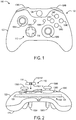
- FIGS. 1 and 2 show an example user input control device in the form of a game controller 100.
- the game controller 100 may be configured to translate user input into control signals that are provided to a computing device, such as a gaming console.
- the control signals may be mapped to commands to control a video game or perform other operations.
- the game controller 100 may be configured to send control signals via a wired or wireless connection with a computing device.
- the game controller 100 includes a plurality of controls 102 configured to generate different control signals responsive to finger manipulation.
- One or more of the plurality of controls 102 may include a removable finger pad 114.
- the removable finger pad 114 may be one of a plurality of differently configured removable controller accessories removably affixable to the game controller 100.
- various differently configured removable controller accessories may have different sizes, shapes, and/or textured surfaces that are preferred by different users or may be suited for particular gaming or other purposes.
- the plurality of controls 102 includes a plurality of action buttons 104 (e.g., 104A, 104B, 104C, 104D, 104E, 104F, 104G, 104H, and 1041), a plurality of joysticks 106 (e.g., a left joystick 106A and a right joystick 106B), a plurality of triggers 108 (e.g., a left trigger 108A and a right trigger 108B), and a directional pad 110.
- the plurality of controls 102 may be coupled to a frame 120 (shown in more detail in FIG. 9 ).
- the frame 120 may be contained collectively within an upper housing portion 122 and a lower housing portion 124 of the game controller 100.
- the upper housing portion 122 and the lower housing portion 124 may cooperate to form a housing that contains at least a portion of each of the plurality of controls 102 that are coupled to the frame 120.
- a printed circuit board 126 may be coupled to the frame 120.
- the printed circuit board 126 may include a plurality of electronic input sensors 128.
- Each electronic input sensor may be configured to generate an activate control signal responsive to interaction with a corresponding control.
- Non-limiting examples of electronic input sensors may include dome switches, tactile switches, Hall Effect sensors, potentiometers, and other electronic sensing components. Any suitable sensor may be implemented in the game controller 100. In some implementations, two or more printed circuit boards may be used.
- the game controller 100 may include any number of controls, any type of controls, any number of electronic input sensors, and any type of electronic input sensors without departing from the scope of this disclosure.
- Each of the action buttons 104 may be configured to activate a corresponding electronic input sensor 128 to generate an activate control signal responsive to being depressed (e.g., via finger manipulation).
- each control signal associated with an action button may be mapped to a video game operation. Different video games may have different mappings of control signals to operations. In some cases, each action button may be mapped to a different operation. In other cases, two action buttons may be mapped to a same operation.
- Each of the joysticks 106 may be configured to provide two-dimensional input that is based on a position of the joystick in relation to a default "center" position.
- the joysticks may interact with electronic input sensors in the form of potentiometers that use continuous electrical activity to provide an analog input control signal.
- Each of the triggers 108 may be configured to provide a variable control signal based on a position of the trigger relative to a default position. For example, as a trigger is pulled farther away from the default position a characteristic of the generated control signal may increase in magnitude.
- the directional pad 110 is the only control on the game controller 100 that is configured to interface with a plurality of differently configured removable controller accessories such that a selected removable controller accessory may be removably affixed to the game controller 100.
- the directional pad 110 includes a mounting platform 112 configured to interface with a selected removable controller accessory in the form of a removable finger pad 114.
- the mounting platform 112 may include a topside 118 including an accessory-retention interface 118' configured to interface with a mounting interface 116' of the removable finger pad 114.
- the directional pad 110 includes the mounting platform 112 and the removable finger pad 114 when the removable finger pad 114 is removably affixed to the mounting platform 112.
- the removable finger pad 114 has a cross-shaped structure that includes a plurality of branches that extend in four different directions (e.g., up, down, left, right).
- the removable finger pad 114 may include a topside 115 that includes a finger interface 115'.
- the finger interface 115' may include any suitable surface, feature, shape, and/or structure configured to be touched and/or manually manipulated by a finger to provide user input.
- the removable finger pad 114 may include an underside 116 that is opposite the topside 115.
- the underside 116 may include the mounting interface 116'.
- the mounting interface 116' may include any suitable surface, feature, shape, and/or structure configured to selectively mate with the mounting platform 112 to removably affix the removable finger pad 114 to the game controller 100.
- the mounting interface 116' of the removable finger pad 114 may have a shape that complements a shape of an accessory-retention interface 118' of the mounting platform 112. Such corresponding interfaces may aid the removable finger pad 114 in aligning with the mounting platform 112 to removably affix the removable finger pad 114 to the game controller 100.
- the mounting platform 112 may include one or more accessory-retention features (examples of which are shown at least at FIGS. 5-6 and 14-19 ) configured to removably affix various removable controller accessories to game controller 100 without the use of any tools.
- accessory-retention features may allow for differently configured removable controller accessories to be quickly and easily interchanged without the use of tools.
- the directional pad 110 may be configured to reside in a default posture when no touch force is applied to the directional pad 110. In the default posture, the directional pad 110 does not cause any of the plurality of electronic input sensors 128 to generate an activate control signal indicative of touch input. Further, the directional pad 110 may be configured to move from the default posture to a selected activation posture responsive to a touch force being applied to the directional pad 110.
- the selected activation posture may be one of a plurality of different activation postures that each generate a different activate control signal or combination of activate control signals by interfacing with different electronic input sensors.
- the activation signal indicative of touch input produced in the selected activation posture may be any signal that differs from a signal or lack thereof produced in the default posture.
- the activation signal may correspond to a supply voltage (e.g., VDD) of the game controller 100 and the signal produced in the default state may correspond to a relative ground. (e.g., 0).
- the activation signal may correspond to a relative ground and the signal produced in the default state may correspond to the supply voltage of the game controller 100.
- the directional pad 110 is depressable in four different directions (e.g., up, down, left, and right) to interface with different electronic input sensors that generate different activate control signals.
- the four different directions may correspond to four different activation postures that generate four different activate control signals to provide four-way directional input.
- combinations of activate control signals corresponding to pressing the directional pad 110 in two directions (e.g., up and left) at one time may be interpreted as additional activation postures corresponding to diagonals in between the four directions to provide eight-way directional input.
- the directional pad 110 may include a number of directions different than four or eight.
- the directional pad 110 may include two or more different directions.
- the mounting platform 112 may be further configured such that when a removable controller accessory is not affixed to the mounting platform 112, a touch force may be applied directly to the mounting platform 112.
- the mounting platform 112 may be configured to translate the touch force into movement of the mounting platform 112 that applies an activation force to one or more electronic input sensors to generate one or more different control signals.
- the mounting platform 112 may function as a directional pad itself when a removable controller accessory is not affixed to the mounting platform 112.
- an activation force may include an amount of force sufficient to actuate a dome switch.
- the activation force may be any suitable amount of force to activate an electronic input sensor.
- the mounting platform 112 may translate a touch force to an activation force
- the mounting platform 112 may otherwise differ from a traditional directional pad.
- the mounting platform 112 may be recessed from a surface of the upper housing portion 122 of the game controller 100 in order to accommodate a thickness of the removable finger pad 114.
- the removable finger pad 114 will not excessively protrude from the mounting platform 112 and interfere with operation of other controls (e.g., joystick 106A) of the game controller 100.
- the topside 118 of the mounting platform 112 may have abrupt edges that are configured to mate with the finger pad 114.
- traditional directional pads may have edges and surfaces that are contoured to comfortably accommodate a user's thumb.
- the directional pad 110 is the only control of the plurality of controls 102 on the game controller 100 that is configured to removably affix differently configured removable controller accessories to the game controller 100.
- the game controller 100 may include more than one control that is configured to removably affix differently configured removable controller accessories to the game controller 100.
- the game controller 100 may include different types of controls other than the directional pad 110 that are configured to removably affix differently configured removable controller accessories to the game controller.
- one or more of the joysticks, action buttons, or triggers may be configured to removably affix differently configured removable controller accessories to the game controller 100.
- each such control may be configured to interact with a different group of removable controller accessories.
- the different removable controller accessories in a given group may have a same mounting interface that is configured to be removably affixed to a particular control.
- a selected removable controller accessory may only be compatible with one of the two controls.
- both controls may be configured in the same manner such that a selected removable controller accessory may be compatible to be removably affixable to both controls.
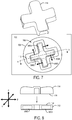
- FIGS. 3 and 4 show interfacing sides of the mounting platform 112 and the removable finger pad 114.
- FIG. 3 shows the topside 118 (e.g., the accessory-retention interface) of the mounting platform 112.
- the mounting platform 112 includes a cross-shaped protrusion 300 that extends from a base piece 302.
- the cross-shaped protrusion includes a plurality of branches 304 (e.g., 304A, 304B, 304C, 304D) that extend in different directions (e.g., up, down, left, right).
- each of the plurality of branches 304 have the same length.
- different branches of the cross-shaped protrusion 300 may have different lengths.
- the mounting platform 112 may include any suitable number of branches that extend in any suitable direction(s).
- the mounting platform 112 may include an accessory-retention interface 118 having a non-branch shape.
- the accessory-retention interface 118 may include a circle, triangle, square, star, or other shape.
- the base piece 302 includes a plurality of mounting tabs 306 (e.g., 306A, 306B, 306C) that are configured to interact with the frame 120 (shown in more detail in FIG. 9 ) to couple the mounting platform 112 to the game controller 100.
- the plurality of mounting tabs 306 may be inserted into corresponding mounting brackets 902 (shown in FIG. 9 ) of the frame 120 to inhibit the mounting platform 112 from twisting in the game controller 100.
- FIG. 4 shows the underside 116 of the removable finger pad 114.
- the underside 116 may include a mounting interface 116' configured to have a shape that complements the shape of the accessory-retention interface (e.g., the cross-shaped protrusion 300) of the mounting platform 112.
- the underside 116 of the removable finger pad 114 may be concave to form a hollowed out cross-shaped cavity 400 including a plurality of valleys 402 (e.g., 402A, 402B, 402C, 402D).
- the cross-shaped cavity 400 may be sized slightly larger than the cross-shaped protrusion 300 such that when the removable finger pad 114 is installed on the mounting platform 112, the cross-shaped cavity 400 covers the cross-shaped protrusion 300.
- the plurality of valleys 402 may extend downward over the plurality of branches 304.
- the height of the cross-shaped protrusion 300 may be at least as great as a depth of the cross-shaped cavity 400 such that when the removable finger pad 114 is installed on the mounting platform 112, a floor 404 of the cross-shaped cavity 400 rests on the cross-shaped protrusion 300.
- the removable finger pad 114 may include a plurality of grip notches 406 (e.g., 406A, 406B). Each of the plurality of grip notches 406 may be positioned on an exterior side 408 of each branch of the cross shape that spans between the topside 115 and the underside 116. The plurality of grip notches 406 may be configured to be gripped by fingers of a user to facilitate easy removal of the removable finger pad 114 from the mounting platform 112.
- the removable finger pad 114 may include any suitable number of grip notches 406, including zero grip notches.
- the removable finger pad 114 may be made at least partially of ferromagnetic material, and the removable finger pad 114 may be removably affixable to the mounting platform 112 through a magnetic attraction between a plurality of magnets 506 (shown in FIG. 5 ) and the ferromagnetic material of the removable finger pad 114.
- the removable finger pad 114 may be a single ferromagnetic metal part.
- the metal part may be injection-molded.
- the part may be machined from a single piece of metal.
- the removable finger pad 114 may be an assembly including one or more ferromagnetic parts.
- FIG. 5-6 show an underside 500 of the mounting platform 112.
- the underside 500 of the mounting platform 112 may be configured to interface with the frame 120 (as shown in FIG. 9 ) to couple the mounting platform 112 to the game controller 100.
- the mounting platform 112 may include a pivot piece 502 configured to interface with a socket 904 (shown in FIG. 9 ) of the frame 120.
- the socket 904 and the pivot piece 502 may collectively form a joint about which the mounting platform 112 is pivotable in a plurality of directions (e.g., up, down, left, right) relative to the frame 120.
- the pivot piece 502 may be positioned in the center of the mounting platform 112 such that the mounting platform 112 may pivot in a similar manner (e.g., angle, distance) in each direction. Moreover, the plurality of mounting tabs 306 of the mounting platform 112 may be inserted into the corresponding plurality of mounting brackets 902 of the frame 120 to inhibit the mounting platform 112 from twisting relative to the frame 120, when the mounting platform 112 pivots in a particular direction.
- the mounting platform 112 may assume a directionally-neutral default posture when the pivot piece 502 is centered in the socket 904. Further, the mounting platform 112 may be configured to move from the default posture to an activation posture in which the mounting platform 112 pivots away from the directionally-neutral default posture. For example, the mounting platform 112 may move from the default posture to a selected activation posture responsive to a touch force being applied to the removable finger pad 114.
- the mounting platform 112 may be configured to pivot into any one of four activation postures corresponding to the plurality of branches 304 of the mounting platform 112. In other implementations, the mounting platform 112 may be configured to pivot into any one of eight activation postures corresponding to the plurality of branches 304 as well as the diagonals between the branches. In other implementations, the mounting platform 112 may be configured to pivot into any one of a number of activation postures other than four or eight. For example, the mounting platform 112 may be configured to pivot into any one of two or more activation postures.
- the mounting platform 112 may include a plurality of sensor-activation features herein depicted in the form of projections 504 (e.g., 504A, 504B, 504C, 504D).
- the plurality of projections 504 may be positioned on the underside 500 of the mounting platform 112 to align with a plurality of electronic input sensors 128 (e.g., 128A, 128B, 128C, 128D shown in FIG. 9 ) when the mounting platform 112 is coupled to the frame 120.
- the plurality of projections 504 may hang over (or touch) the plurality of electronic input sensors 128 without activating the plurality of electronic input sensors 128.
- none of the electronic input sensors 128 may generate an activate control signal indicative of user input.
- one or more projections 504 may interface with one or more corresponding electronic input sensors 128 to generate one or more activate control signals indicative of user input. For example, when an "up" touch force is applied to the removable finger pad 114, projection 504A is pushed into corresponding electronic input sensor 128A to generate an activate control signal indicative of user input in the "up" direction.
- the projections 504 are merely one non-limiting example of a sensor-activation feature of the mounting platform 112.
- a sensor-activation feature may take any suitable form.
- the mounting platform 112 may include any suitable number of sensor-activation features configured to interface with any suitable number of electronic input sensors.
- the mounting platform 112 may include a plurality of accessory-retention features herein depicted in the form of magnets 506 (e.g., 506A, 506B, 506C, 506D) configured to removably affix the removable finger pad 114 to the mounting platform 112.
- the plurality of magnets 506 may be positioned in a plurality of troughs 508 (e.g., 508A, 508B, 508C, 508D) formed underneath the cross-shaped protrusion 300 (shown in FIG. 3 ).
- the plurality of troughs 508 may have a depth to accommodate the plurality of magnets 506 such that the plurality of magnets are at least flush (or recessed) with the underside 500 of the mounting platform 112.
- the plurality of magnets 506 may be coupled to the plurality of troughs 508 in any suitable manner.
- the plurality of magnets 506 may be coupled to the plurality of troughs 508 using pressure-sensitive adhesive.
- FIGS. 7-8 show the removable finger pad 114 aligned to be installed on the mounting platform 112.
- the mounting platform 112 is mounted to the frame 120 (as shown in FIG. 9 ), and the mounting platform 112 protrudes through an aperture 700 defined by a rim 702 located on the upper housing portion 122.
- the removable finger pad 114 may be removably affixed to the mounting platform 112 along an interface direction ( ⁇ ).
- the plurality of magnets 506 each may be positioned such that a pole of each magnet extends in a direction (e.g., ⁇ or ⁇ ) that is not parallel to the interface direction ( ⁇ ) between the removable finger pad 114 and the mounting platform 112.
- each magnet may extend in a direction that is perpendicular to the interface direction ( ⁇ ). Further, each magnet may be positioned such that a pole of the magnet is orientated in a direction that is rotated ninety degrees away from a pole of each neighboring magnet.
- Such a magnet orientation may allow the removable finger pad 114 to slide beyond the topside 118 of the mounting platform 112 to allow the removable controller accessory to cover the mounting platform 112. If the plurality of magnets were oriented such that a pole of each magnet extended in the interface direction ( ⁇ ) or a direction parallel to the interface direction, then the underside 116 of the removable finger pad 114 would be attracted to the topside 118 of the mounting platform 112. Such a configuration would make it difficult for the valleys 402 of the removable finger pad 114 to slide over the branches 304 of the cross-shaped protrusion 300.
- the corresponding cross-shaped features of the mounting platform 112 and the removable finger pad 114 may act as accessory-retention features that contribute to making the removable finger pad 114 removably affixable to the mounting platform 112.
- the corresponding cross-shaped features of the mounting platform 112 and the removable finger pad 114 may cooperate to initially align the removable finger pad 114 with the mounting platform 112.
- the plurality of magnets 506 and the ferromagnetic material may cooperate to retain the removable finger pad 114 affixed to the mounting platform 112.
- any suitable number of magnets 506 may be employed to removably affix the removable finger pad 114 to the mounting platform 112.
- magnets 506 may take any suitable form.
- a single large ring magnet may be used in place of the four rectangular magnets of the depicted implementation.
- the mounting platform 112 and the removable finger pad 114 may have a circular or toroidal shape instead of a cross shape.
- the pivot piece 502 may be positioned at the center of the mounting platform 112.
- the plurality of magnets 506 may be oriented in the mounting platform 112 according to any suitable orientation.
- the removable finger pad 114 may include magnets and the mounting platform 112 may be made at least partially of ferromagnetic material that is configured to be attracted to the plurality of magnets of the removable finger pad 114.
- both the removable finger pad 114 and the mounting platform 112 may include magnets that are configured to be attracted to each other.
- FIG. 9 shows a portion of the frame 120 without the mounting platform 112 installed on the frame 120.
- the plurality of mounting brackets 902 may be used to align the mounting platform 112 with the frame 120 such that the pivot piece 502 may interface with the socket 904 to collectively form a joint about which the mounting platform 112 is pivotable in a plurality of directions relative to the frame 120.
- the plurality of mounting brackets 902 e.g., 902A, 902B, 902C
- the printed circuit board 126 may be coupled beneath the frame 120 such that the plurality of electronic input sensors, depicted herein in the form of a plurality of dome switches 128 (e.g., 128A, 128B, 128C, 128D), may be aligned to interact with the plurality of projections 504 when the mounting platform 112 is installed on the frame 120.
- the plurality of dome switches 128 may be recessed relative to the frame 120, and more particularly relative to the socket 904 such that when the mounting platform 112 is in the default posture, the plurality of projections 504 do not activate the plurality of dome switches 128.
- a projection 504 corresponding to the direction may be lowered to activate a corresponding dome switch 128.
- the frame 120 includes a plurality of supports 906 (e.g., 906A, 906B, 906C, 906D) that extend out from the socket 904.
- the plurality of supports 906 may be positioned to align with the plurality of troughs 508 of the mounting platform 112 when the mounting platform 112 is installed on the frame 120.
- each support may be configured to extend at least to an opening of a corresponding trough to maintain a magnet in the trough when the mounting platform 112 is installed on the frame 1120.
- the plurality of supports 906 may act as magnet retention features that may keep the magnets in the troughs even when an adhesive or other coupling mechanism fails.
- FIG. 10 shows a portion of the frame 120 with the mounting platform 112 installed on the frame 120, the removable finger pad 114 removably affixed to the mounting platform 112, and the upper housing portion 122 removed to show the underlying structure.
- a spring clip 1000 may be positioned between the frame 120 and the mounting platform 112, and the plurality of mounting tabs 306 may extend under the spring clip 1000 to couple the mounting platform 112 to the frame 120.
- the spring clip 1000 may be configured to return the mounting platform 112 from an activation posture to the default posture when a touch force to the removable finger pad 114 has been lifted. For example, when the removable finger pad 114 is depressed, the spring clip 1000 resists the depressions and biases the removable finger pad 114 towards popping back up to the default posture.
- the spring clip 1000 may be covered by the upper housing portion 122 (shown in FIG. 2 ) of the game controller 100, and the mounting platform 112 may be exposed via the aperture 700 (as shown in FIG. 7 ) defined by the rim 702 located on the upper housing portion 122.
- different variations of the removable finger pad 114 having differing attributes may be swapped on the mounting platform 112.
- differing attributes may include different branch thickness of the cross shape, different cross height, different branch angles, different materials, different surface textures, additional tactile features (e.g., bumps), different colors, different artwork, and other attributes.
- FIGS. 11-13 show non-limiting examples of some such removable controller accessories.
- FIG. 11 shows a removable controller accessory 1100 including a topside 1102 and an underside 1104 opposite the topside 1102.
- the topside 1102 includes a finger interface 1106 sized and shaped for manual manipulation by a finger.
- the finger interface 1106 includes a concave dish having a smooth surface.
- Such a finger interface may mimic a contour of a user's thumb.
- the smooth surface of the rounded dish may be useful for applications where large circular rotations of the directional pad may be performed frequently.
- the finger interface 1106 may include a concave dish having a textured surface (e.g., bumps, ridges, depressions, or patterns).
- the underside 1104 includes a mounting interface 1108 configured to selectively mate with an accessory-retention feature of the mounting platform 112 of the game controller 100 to removably affix the removable controller accessory 1100 to the mounting platform 112.
- the mounting interface 1108 may include a cross-shaped concave cavity that is configured to mate with the cross-shaped protrusion 300 of the mounting platform 112.
- the mounting interface 1108 may have features that compliment features of the mounting interface 116' of the removable finger pad 114 (shown in FIG. 4 ).
- the removable controller accessory 1100 may be made at least partially of ferromagnetic material that is configured to have a magnetic attraction to the magnets 506 of the mounting platform 112.
- FIG. 12 shows a removable controller accessory 1200 including a topside 1202 and an underside 1204 that is opposite the topside 1202.
- the topside 1202 includes a finger interface 1206 depicted in the form of a joystick.
- the joystick may provide a movable shaft or lever that can be easily flicked in a particular direction. For example, such a lever may be useful for applications where the same control (or direction) is activated repeatedly, such as to scroll through items in an inventory.
- the underside 1204 includes a mounting interface 1208 configured in the same manner as the mounting interface 1108 of the removable controller accessory 1100.
- FIG. 13 shows a removable controller accessory 1300 including a topside 1302 and an underside 1304 that is opposite the topside 1302.
- the topside 1302 includes a finger interface 1306 depicted in the form of a concave dish including a plurality of planar facets.
- the underside 1304 includes a mounting interface 1308 configured in the same manner as the mounting interface 1108 of the removable controller accessory 1100 and the mounting interface 1208 of the removable controller accessory 1200.
- removable controller accessories 114, 1100, 1200, and 1300 all have similarly configured mounting interfaces that are configured to mate with the mounting platform 112, each of these removable controller accessories may be quickly and easily swapped on the game controller 100.
- the mounting platform 112 of the game controller 100 alternatively or additionally may include one or more non-magnetic accessory-retention features.
- a removable controller accessory may include a mounting interface configured to mate with such accessory-retention features to removably affix the removable controller accessory to the mounting platform.
- FIGS. 14-15 show an example configuration in which a snap fastener is employed as an accessory-retention feature to removably affix a removable controller accessory 1500 to a mounting platform 1400.
- the mounting platform 1400 includes a snap fastener 1402.
- the snap fastener 1402 may be configured to interlock with a corresponding mating feature 1502 of the removable controller accessory 1500 to removably affix the removable controller accessory 1500 to the mounting platform 1400.
- the mounting platform 1400 also includes a plurality of alignment features 1402 (e.g., 1402A, 1402B, 1403C, 1402D) configured to fit into a plurality of cavities 1502 (e.g., 1502A, 1502B, 1502C, 1502D) of the removable controller accessory 1500 to prevent the removable controller accessory 1500 from translating or rotating relative to the mounting platform 1400.
- a plurality of alignment features 1402 e.g., 1402A, 1402B, 1403C, 1402D
- cavities 1502 e.g., 1502A, 1502B, 1502C, 1502D
- any suitable number of cooperating snap fasteners, mating features, and/or alignment features may be employed on the mounting platform 1400 and the removable controller accessory 1500 to removably affix the removable controller accessory 1500 to the mounting platform 1400.
- the snap fasteners may take any suitable form.
- the snap fasteners may be positioned either at the center of the mounting platform, towards the extremities, or both.
- the snap fastener(s) 1402 may be located on the removable controller accessory 1500 and the mating feature(s) 1502 may be located on the mounting platform 1400.
- a subset of snap fasteners and mating features may be located on the removable controller accessory 1500 and another subset of snap fasteners and mating features may be located on the mounting platform 1400.
- FIGS. 16-17 show an example configuration in which complimentary wedge surfaces are employed as accessory-retention features to removably affix a removable controller accessory 1700 to a mounting platform 1600.
- the mounting platform 1600 includes a cross-shaped alignment feature 1602.
- the alignment feature 1602 may be either raised or depressed to align with a cross-shaped alignment feature 1702 of the removable controller accessory 1700.
- the mounting platform 1600 includes a protrusion 1604 that includes a plurality of wedge surfaces 1606 (e.g., 1606A, 1606B, 1606C, 1606D, 1606E, 1606F, 1606G, 1606H).
- the removable controller accessory 1700 includes a cavity 1704 that includes a plurality of wedge surfaces 1706 (e.g., 1706A, 1706B, 1706C, 1706D, 1706E, 1706F, 1706G, 1706H).
- the cavity 1704 may mate with the protrusion 1604 of the mounting platform such that complimentary wedge surfaces of the mounting platform 1600 and the removable controller accessory 1700 interface with each other.
- friction between the complimentary wedge surfaces may removably affix the removable controller accessory 1700 to the mounting platform 1600.
- the complimentary wedge surfaces may have high-friction textures that increase friction between complimentary wedge surfaces.
- the mounting platform 1600 and the removable controller accessory 1700 may include any suitable number of complimentary pairs of wedge surfaces.
- the complimentary pairs of wedge surfaces may take any suitable form (e.g., different angles, lengths, orientations).
- FIGS. 18-19 show an example configuration in which a twist-to-lock mechanism is employed as an accessory-retention feature to removably affix a removable controller accessory 1800 to a mounting platform 1802.
- the removable controller accessory 1800 includes a male portion 1804 and a radial pin 1806 that extends radially outward from the male portion 1804.
- the mounting platform 1802 includes a female portion 1808 having a side in which an L-shaped slot 1810 is formed.
- the male portion 1804 may be inserted into the female portion 1808 until the radial pin 1806 is stopped at a heel of the L-shaped slot 1810.
- the removable controller accessory 1800 may be rotated clockwise to move the radial pin 1806 to a toe of the L-shaped slot 1810 to affix the removable controller accessory 1800 to the mounting platform 1802.
- the twist-to-lock mechanism may take any suitable form.
- the removable controller accessory may include any suitable number of radial pins.
- the mounting platform 1802 may include a slot having any suitable shape.
- the male portion may be biased upward such that radial pin is pushed upward into a toe catch of an L-shaped slot.
- the radial pin may be outwardly biased, and the toe of the slot may include a depressable catch. In such a configuration the catch may be depressed to release the pin from the toe in order for the male portion to be twisted relative to the female portion.
- the mounting platform and the removable controller accessory may include cooperating screw threads that act as accessory-retention features to removably affix the removable controller accessory to the mounting platform by screwing the removable controller accessory onto the mounting platform.
- a game controller comprises an electronic input sensor, and a mounting platform including an accessory-retention feature and a sensor-activation feature.
- the accessory-retention feature may be configured to removably affix a selected removable controller accessory to the mounting platform.
- the selected removable controller accessory may be one of a plurality of differently configured removable controller accessories removably affixable to the mounting platform.
- the mounting platform may be configured to move from a default posture to an activation posture responsive to finger manipulation of the selected removable controller accessory when the selected removable controller accessory is affixed to the mounting platform.
- the sensor-activation feature interfaces with the electronic input sensor to generate an activate control signal in the activation posture.
- the accessory-retention feature includes one or more magnets.
- the selected removable controller accessory is made at least partially of ferromagnetic material.
- the selected removable controller accessory is removably affixable to the mounting platform through a magnetic attraction between the one or more magnets and the ferromagnetic material.
- the one or more are each positioned such that a pole of each magnet extends in a direction that is not parallel to an interface direction between the selected removable controller accessory and the mounting platform.
- the selected removable controller accessory includes one or more magnets.
- the mounting platform is made at least partially of ferromagnetic material.
- the selected removable controller accessory is removably affixable to the mounting platform through a magnetic attraction between the one or more magnets and the ferromagnetic material.
- the game controller comprises a frame including a socket configured to interface with a pivot piece of the mounting platform. The socket and the pivot piece collectively form a joint about which the mounting platform is pivotable in a plurality of directions relative to the frame.
- the accessory-retention feature includes one or more magnets positioned in one or more troughs formed in the mounting platform.
- the frame includes one or more supports that extend at least to an opening of the one or more troughs to maintain the one or more magnets in the one or more troughs when the mounting platform is installed on the frame.
- the selected removable controller accessory includes a finger interface and a mounting interface.
- One or more other of the plurality of differently configured removable controller accessories have a differently configured finger interface and a same mounting interface as the selected removable controller accessory.
- the accessory-retention feature includes one or more snap fasteners configured to interlock with one or more corresponding mating features on the selected removable controller accessory to removably affix the selected removable controller accessory to the mounting platform.
- the accessory-retention feature and the selected removable controller accessory form a twist-to-lock mechanism.
- the mounting platform includes a cross-shaped protrusion.
- the selected removable controller accessory has a cross-shaped concave mounting interface configured to cover the cross-shaped protrusion when the selected removable controller accessory is removably affixed to the mounting platform.
- a game controller comprises an electronic input sensor and a mounting platform including one or more magnets and a sensor-activation feature.
- the one or more magnets may be configured to magnetically attract a selected removable controller accessory made at least partially of ferromagnetic material to removably affix the selected removable controller accessory to the mounting platform.
- the selected removable controller accessory may be one of a plurality of differently configured removable controller accessories removably affixable to the mounting platform.
- the mounting platform may be configured to move from a default posture to an activation posture responsive to finger manipulation of the selected removable controller accessory when the selected removable controller accessory is affixed to the mounting platform.
- the sensor-activation feature interfaces with the electronic input sensor to generate an activate control signal in the activation posture.
- the one or more magnets are each positioned such that a pole of the magnet extends in a direction that is not parallel to an interface direction between the selected removable controller accessory and the mounting platform.
- the game controller further comprises a frame including a socket configured to interface with a pivot piece of the mounting platform. The socket and the pivot piece collectively form a joint about which the mounting platform is pivotable in a plurality of directions relative to the frame.
- the one or more magnets are positioned in one or more troughs formed in the mounting platform.
- the frame includes one or more supports that extend at least to an opening of the one or more troughs to maintain the one or more magnets in the one or more troughs when the mounting platform is installed on the frame.
- the selected removable controller accessory includes a finger interface and a mounting interface.
- One or more other of the plurality of differently configured removable controller accessories have a differently configured finger interface and a same mounting interface as the selected removable controller accessory.
- the mounting platform includes a cross-shaped protrusion.
- the selected removable controller accessory has a cross-shaped concave mounting interface configured to cover the cross-shaped protrusion when the selected removable controller accessory is removably affixed to the mounting platform.
- a game controller comprises a plurality of electronic input sensors, and a mounting platform including a cross-shaped protrusion having four branches, a plurality of sensor-activation features corresponding to the four branches of the cross-shaped protrusion, and an accessory-retention feature.
- the accessory-retention feature may be configured to removably affix a removable controller accessory to the mounting platform.
- the removable controller accessory may have a cross-shaped concave mounting interface configured to cover the cross-shaped protrusion when the removable controller accessory is removably affixed to the mounting platform.
- the mounting platform may be configured to move from a default posture to a selected activation posture responsive to finger manipulation of the removable controller accessory when the removable controller accessory is affixed to the mounting platform.
- the selected activation posture may be one of four activation postures corresponding to the four branches of the cross-shaped protrusion.
- a sensor-activation feature associated with a branch corresponding to the selected activation posture interfaces with a corresponding electronic input sensor to generate an activate control signal in the selected activation posture.
- the mounting platform includes a plurality of troughs formed underneath the cross-shaped protrusion.
- the retention feature includes a plurality of magnets positioned in the plurality of troughs. Each magnet is positioned such that a pole of the magnet extends in a direction that is not parallel to an interface direction between the removable controller accessory and the mounting platform.
- the removable controller accessory is made at least partially of ferromagnetic material.
- the removable controller accessory is removably affixable to the mounting platform through a magnetic attraction between the plurality of magnets and the ferromagnetic material.
- the game controller comprises a frame including a socket configured to interface with a pivot piece of the mounting platform, the socket and the pivot piece collectively forming a joint about which the mounting platform is pivotable in a plurality of directions relative to the frame.
- the removable controller accessory is one of a plurality of differently configured removable controller accessories removably affixable to the mounting platform.
- the removable controller accessory includes a finger interface and a mounting interface.
- One or more other of the plurality of differently configured removable controller accessories may have a differently configured finger interface and a same mounting interface as the removable controller accessory.
Landscapes
- Engineering & Computer Science (AREA)
- Multimedia (AREA)
- Human Computer Interaction (AREA)
- Position Input By Displaying (AREA)
- User Interface Of Digital Computer (AREA)
Claims (8)
- Spielcontroller, umfassend:einen elektronischen Eingabesensor; undeine Montageplattform einschließlich eines Zubehörrückhaltemerkmals und eines Sensoraktivierungsmerkmals, wobei das Zubehörrückhaltemerkmal konfiguriert ist, um ein ausgewähltes abnehmbares Controllerzubehör abnehmbar an der Montageplattform zu befestigen, wobei das ausgewählte abnehmbare Controllerzubehör eines ist von einer Vielzahl von unterschiedlich konfigurierten abnehmbaren Controllerzubehören, die abnehmbar an der Montageplattform befestigbar sind, und wobei die Montageplattform konfiguriert ist, um sich von einer Standardstellung zu einer Aktivierungsstellung zu bewegen, die auf Fingerbedienung des ausgewählten abnehmbaren Controllerzubehörs reagiert, wenn das ausgewählte abnehmbare Controllerzubehör an der Montageplattform befestigt ist; und wobei das Sensoraktivierungsmerkmal mit dem elektronischen Eingabesensor koppelt, um ein Aktiviersteuersignal in der Aktivierungsstellung zu erzeugen,wobei das Zubehörrückhaltemerkmal einen oder mehrere Magnete einschließt, wobei das ausgewählte abnehmbare Controllerzubehör mindestens teilweise aus ferromagnetischem Material hergestellt ist, und wobei das ausgewählte abnehmbare Controllerzubehör durch eine magnetische Anziehung zwischen dem/den einen oder mehreren Magneten und dem ferromagnetischen Material abnehmbar an der Montageplattform befestigbar ist,wobei der/die eine oder mehreren Magnete jeweils so positioniert sind, dass sich ein Pol von jedem Magneten in eine Richtung erstreckt, die nicht parallel zu einer Schnittstellenrichtung zwischen dem ausgewählten abnehmbaren Controllerzubehör und der Montageplattform ist.
- Spielcontroller nach Anspruch 1, weiter umfassend
einen Rahmen einschließlich eines Sockels, konfiguriert, um mit einem Schwenkteil der Montageplattform zu koppeln, wobei der Sockel und das Schwenkteil gemeinsam ein Gelenk bilden, um welches die Montageplattform in eine Vielzahl von Richtungen relativ zum Rahmen schwenkbar ist. - Spielcontroller nach Anspruch 2, wobei das Zubehörrückhaltemerkmal einen oder mehrere Magnete einschließt, positioniert in einer oder mehreren in der Montageplattform gebildeten Vertiefungen, und wobei der Rahmen eine oder mehrere Stützen einschließt, die sich mindestens zu einer Öffnung der einen oder mehreren Vertiefungen erstrecken, um den/die einen oder mehreren Magnete in der/den einen oder mehreren Vertiefungen zu halten, wenn die Montageplattform auf dem Rahmen installiert ist.
- Spielcontroller nach Anspruch 1, wobei das ausgewählte abnehmbare Controllerzubehör eine Fingerschnittstelle und eine Montageschnittstelle einschließt, und wobei ein oder mehrere andere von der Vielzahl von unterschiedlich konfigurierten abnehmbaren Controllerzubehören eine unterschiedlich konfigurierte Fingerschnittstelle und eine gleiche Montageschnittstelle als das ausgewählte abnehmbare Controllerzubehör aufweisen.
- Spielcontroller nach Anspruch 1, wobei das Zubehörrückhaltemerkmal einen oder mehrere Schnappverschlüsse einschließt, konfiguriert, um mit einem oder mehreren entsprechenden Gegenmerkmalen auf dem ausgewählten abnehmbaren Controllerzubehör ineinanderzugreifen, um das ausgewählte abnehmbare Controllerzubehör abnehmbar an der Montageplattform zu befestigen.
- Spielcontroller nach Anspruch 1, wobei das Zubehörrückhaltemerkmal und das ausgewählte a bnehmbare Controllerzubehör einen "Twist-to-lock"-Mechanismus bilden.
- Spielcontroller nach Anspruch 1, wobei die Montageplattform einen kreuzförmigen Vorsprung einschließt, und wobei das ausgewählte abnehmbare Controllerzubehör eine kreuzförmige konkave Montageschnittstelle aufweist, die konfiguriert ist, um den kreuzförmigen Vorsprung zu bedecken, wenn das ausgewählte abnehmbare Controllerzubehör abnehmbar an der Montageplattform befestigt ist.
- Spielcontroller, umfassend:einen elektronischen Eingabesensor; undeine Montageplattform einschließlich eines Zubehörrückhaltemerkmals und eines Sensoraktivierungsmerkmals, wobei das Zubehörrückhaltemerkmal konfiguriert ist, um ein ausgewähltes abnehmbares Controllerzubehör abnehmbar an der Montageplattform zu befestigen, wobei das ausgewählte abnehmbare Controllerzubehör eines ist von einer Vielzahl von unterschiedlich konfigurierten abnehmbaren Controllerzubehören, die abnehmbar an der Montageplattform befestigbar sind, und wobei die Montageplattform konfiguriert ist, um sich von einer Standardstellung zu einer Aktivierungsstellung zu bewegen, die auf Fingerbedienung des ausgewählten abnehmbaren Controllerzubehörs reagiert, wenn das ausgewählte abnehmbare Controllerzubehör an der Montageplattform befestigt ist; und wobei das Sensoraktivierungsmerkmal mit dem elektronischen Eingabesensor koppelt, um ein Aktiviersteuersignal in der Aktivierungsstellung zu erzeugen,wobei das ausgewählte abnehmbare Controllerzubehör einen oder mehrere Magnete einschließt, wobei die Montageplattform mindestens teilweise aus ferromagnetischem Material hergestellt ist, und wobei das ausgewählte abnehmbare Controllerzubehör durch eine magnetische Anziehung zwischen dem/den einen oder mehreren Magneten und dem ferromagnetischen Material abnehmbar an der Montageplattform befestigbar ist,wobei der/die eine oder mehreren Magnete jeweils so positioniert sind, dass sich ein Pol von jedem Magneten in eine Richtung erstreckt, die nicht parallel zu einer Schnittstellenrichtung zwischen dem ausgewählten abnehmbaren Controllerzubehör und der Montageplattform ist.
Applications Claiming Priority (2)
| Application Number | Priority Date | Filing Date | Title |
|---|---|---|---|
| US14/702,520 US10124249B2 (en) | 2015-05-01 | 2015-05-01 | Game controller with removable controller accessory |
| PCT/US2016/026304 WO2016178787A1 (en) | 2015-05-01 | 2016-04-07 | Game controller with removable controller accessory |
Publications (2)
| Publication Number | Publication Date |
|---|---|
| EP3288654A1 EP3288654A1 (de) | 2018-03-07 |
| EP3288654B1 true EP3288654B1 (de) | 2019-09-04 |
Family
ID=55802478
Family Applications (1)
| Application Number | Title | Priority Date | Filing Date |
|---|---|---|---|
| EP16717754.2A Active EP3288654B1 (de) | 2015-05-01 | 2016-04-07 | Abnehmbares zubehör für spielkontroller |
Country Status (4)
| Country | Link |
|---|---|
| US (2) | US10124249B2 (de) |
| EP (1) | EP3288654B1 (de) |
| CN (1) | CN107530586A (de) |
| WO (1) | WO2016178787A1 (de) |
Families Citing this family (27)
| Publication number | Priority date | Publication date | Assignee | Title |
|---|---|---|---|---|
| US10124249B2 (en) | 2015-05-01 | 2018-11-13 | Microsoft Technology Licensing, Llc | Game controller with removable controller accessory |
| US10137364B2 (en) | 2015-06-09 | 2018-11-27 | Microsoft Technology Licensing, Llc | Game controller with removable magnetic button |
| US10940386B2 (en) * | 2015-10-09 | 2021-03-09 | Ironburg Inventions Limited | Games controller |
| JP6730918B2 (ja) | 2016-12-09 | 2020-07-29 | 株式会社ホリ | コントローラ、カバー部材 |
| US12194375B2 (en) | 2017-01-25 | 2025-01-14 | Kieran S. Lyden | Game controller |
| CN106730826A (zh) * | 2017-03-10 | 2017-05-31 | 成都缔客行势网络科技有限公司 | 适用于fps游戏的游戏手柄 |
| USD866664S1 (en) * | 2017-06-12 | 2019-11-12 | Performance Designed Products Llc | Face plate for a video game controller |
| USD867458S1 (en) | 2017-06-12 | 2019-11-19 | Performance Designed Products Llc | Face plate for a video game controller |
| USD853384S1 (en) * | 2017-10-04 | 2019-07-09 | Performance Designed Products Llc | Video game controller |
| USD850447S1 (en) * | 2017-10-04 | 2019-06-04 | Performance Designed Products Llc | Video game controller |
| US10814222B2 (en) | 2018-09-21 | 2020-10-27 | Logitech Europe S.A. | Gaming controller with adaptable input configurations |
| CN108992921B (zh) * | 2018-10-16 | 2020-04-21 | 东莞市名键电子科技有限公司 | 光电手柄摇杆组件 |
| FR3087664B1 (fr) | 2018-10-25 | 2021-09-10 | Bigben Interactive | Manette de jeu comportant au moins un element de reglage amovible permettant le reglage de l’angle d’arret d’un organe de commande pivotant de la manette |
| JP1642996S (de) * | 2018-11-09 | 2019-10-07 | ||
| US10888776B2 (en) * | 2018-11-27 | 2021-01-12 | Valve Corporation | Handheld controllers with detachable overlays |
| US11628352B2 (en) | 2020-04-01 | 2023-04-18 | Sony Interactive Entertainment Inc. | Two-axis controller interface with reconfigurable orientation |
| US11400364B2 (en) * | 2020-04-01 | 2022-08-02 | Sony Interactive Entertainment Inc. | Controller with swappable input controls |
| US11565173B2 (en) | 2020-04-01 | 2023-01-31 | Sony Interactive Entertainment Inc. | Controller with swappable, rotatable button cluster |
| EP4264398B1 (de) | 2020-12-17 | 2025-08-27 | Razer (Asia-Pacific) Pte. Ltd. | Direktionale pad-anordnung und handsteuergerät |
| US11565174B2 (en) * | 2021-05-07 | 2023-01-31 | Microsoft Technology Licensing, Llc | Twist-lock directional input devices for gamepads |
| US11975272B2 (en) * | 2021-08-04 | 2024-05-07 | Robert Gordon Durling, JR. | Magnetic thumb-tip covers interface to magnetic thumb-stick covers, magnetic thumb-stick extensions and magnetic directional pad thumb-stick apparatus for enhanced gaming performance |
| WO2023058115A1 (ja) * | 2021-10-05 | 2023-04-13 | 日本電信電話株式会社 | 入力装置、入力システムおよび入力方法 |
| US12453923B2 (en) | 2021-11-02 | 2025-10-28 | Panda Hardware LLC | Game controller with replaceable joystick gate(s) |
| EP4459439A4 (de) * | 2021-12-28 | 2026-01-07 | Sony Interactive Entertainment Inc | Eingabevorrichtung und bedienknüppeleinheit |
| CN120077459A (zh) * | 2022-10-21 | 2025-05-30 | 索尼互动娱乐股份有限公司 | 输入设备和操作按钮 |
| US12268957B2 (en) * | 2023-01-05 | 2025-04-08 | Dell Products L.P. | Directional pads with dynamic tactile features and methods of using the same |
| GB2639625A (en) * | 2024-03-20 | 2025-10-01 | Sony Interactive Entertainment Inc | Customisable peripheral device and associated method |
Family Cites Families (76)
| Publication number | Priority date | Publication date | Assignee | Title |
|---|---|---|---|---|
| US559416A (en) | 1896-05-05 | Electric push-button | ||
| US3996441A (en) | 1973-07-09 | 1976-12-07 | Shigeo Ohashi | Switch with rocker actuator having detachable cover |
| US4292481A (en) | 1975-07-16 | 1981-09-29 | Barnes Wayne R | Decorative applique and decorative faceplate assembly for push-button telephones |
| US4484743A (en) * | 1983-03-14 | 1984-11-27 | David A. Bartz | Mounting system for a video control unit |
| US4575591A (en) * | 1984-04-23 | 1986-03-11 | Lugaresi Thomas J | Joystick attachment for a computer keyboard |
| US4755072A (en) | 1986-10-15 | 1988-07-05 | Hoornweg Andries P | Removable, transparent, colored key caps for color coding a keyboard |
| US5239450A (en) | 1991-03-28 | 1993-08-24 | Wall Stephen F | Illuminated button with interchangeable image |
| US6343991B1 (en) | 1997-10-01 | 2002-02-05 | Brad A. Armstrong | Game control with analog pressure sensor |
| US6102802A (en) | 1997-10-01 | 2000-08-15 | Armstrong; Brad A. | Game controller with analog pressure sensor(s) |
| US6135886A (en) | 1997-10-01 | 2000-10-24 | Armstrong; Brad A. | Variable-conductance sensor with elastomeric dome-cap |
| GB2295662A (en) | 1994-11-28 | 1996-06-05 | Wah Leung Chan | Joystick eg for video games |
| US5883690A (en) * | 1997-05-30 | 1999-03-16 | Z-Products | Joystick adapter for a directional keypad on a game controller |
| US5995034A (en) | 1997-09-09 | 1999-11-30 | Primax Electronics Ltd. | Computer joystick with a removable joystick handle |
| AUPP702098A0 (en) | 1998-11-09 | 1998-12-03 | Silverbrook Research Pty Ltd | Image creation method and apparatus (ART73) |
| US6617982B1 (en) | 1999-04-23 | 2003-09-09 | Sony Computer Entertainment Inc. | Operating device |
| US20020000975A1 (en) | 2000-01-18 | 2002-01-03 | Perkins Mark H. | Keyboard with interchangeable device |
| US20020052237A1 (en) | 2000-07-21 | 2002-05-02 | Magill Christopher L. | Operating device with pendulum joystick |
| ATE294014T1 (de) | 2000-10-31 | 2005-05-15 | Midway Amusement Games Llc | Modulare schossbedienungskonsole für videospiele |
| US6510048B2 (en) | 2001-01-04 | 2003-01-21 | Apple Computer, Inc. | Keyboard arrangement |
| US20020128064A1 (en) | 2001-03-06 | 2002-09-12 | Sobota John F. | Game controller |
| JP3608726B2 (ja) | 2001-04-19 | 2005-01-12 | 株式会社ソニー・コンピュータエンタテインメント | コントローラ |
| US6747578B1 (en) | 2001-04-27 | 2004-06-08 | Palmone, Inc. | Integrated removable functional faceplate for portable computer system |
| US6994445B1 (en) | 2002-09-04 | 2006-02-07 | Pomes Nick J | Cap with underside light |
| ITTO20020863A1 (it) | 2002-10-04 | 2004-04-05 | Comau Spa | Terminale portatile di comando, programmazione e/ o |
| US20040188933A1 (en) * | 2003-03-31 | 2004-09-30 | Paul Siciliano | Video game controller thumb pad |
| US20060025217A1 (en) | 2004-03-29 | 2006-02-02 | Saied Hussaini | Ergonomically cofigurable video game controller |
| US7758424B2 (en) * | 2004-05-11 | 2010-07-20 | Mattel, Inc. | Game controller with interchangeable controls |
| US20050255916A1 (en) | 2004-05-12 | 2005-11-17 | Paul Chen | Adaptable game controller |
| US7927216B2 (en) | 2005-09-15 | 2011-04-19 | Nintendo Co., Ltd. | Video game system with wireless modular handheld controller |
| US7425681B2 (en) | 2006-06-12 | 2008-09-16 | Shaojie Xu | Decorative switch assembly |
| US8096884B2 (en) | 2006-11-09 | 2012-01-17 | Igt | Gaming machine with adjustable button panel |
| CN101663074B (zh) | 2006-11-10 | 2012-03-28 | 雷泽亚太有限公司 | 可以人机工程学的方式配置的游戏控制器 |
| US8932135B2 (en) | 2007-04-19 | 2015-01-13 | Adam W. Coe | Game controller |
| US7993203B1 (en) | 2007-05-29 | 2011-08-09 | KontrolFreek, LLC | Control stick adapter |
| WO2009018270A1 (en) | 2007-07-29 | 2009-02-05 | E.B. Carlson Marketing, Inc. | Video game device with interchangeable body and controller, strum sensor, and methods of use |
| US20090054146A1 (en) | 2007-08-23 | 2009-02-26 | Michael Epstein | Configurable single handed video game controller |
| US20090239665A1 (en) | 2007-12-31 | 2009-09-24 | Michael Minuto | Brandable thumbstick cover for game controllers |
| US8488069B2 (en) | 2008-08-04 | 2013-07-16 | Casino Technology Ad | Electronic display with push buttons |
| WO2010120780A1 (en) | 2009-04-13 | 2010-10-21 | Sg Labs, Llc | Hand-manipulable interface methods and systems |
| US20100298053A1 (en) | 2009-05-19 | 2010-11-25 | Icontrol Enterprises, Llc | Device for enhancing operation of a game controller and method of using the same |
| GB2463341B (en) | 2009-06-04 | 2011-09-14 | Cheng Uei Prec Ind Co Ltd | Key switch |
| US20100328203A1 (en) | 2009-06-24 | 2010-12-30 | Weistech Technology Co., Ltd. | Removable pads with a carrying case for a portable electronic device with a touch screen |
| US20110011712A1 (en) | 2009-07-17 | 2011-01-20 | Sony Ericsson Mobile Communications Ab | Adjustable input device |
| US8784208B2 (en) | 2009-09-14 | 2014-07-22 | Jeffrey Todd Borrel | Game control thumb grip |
| US8241126B2 (en) | 2009-11-04 | 2012-08-14 | Valve Corporation | Video game controller having user swappable control components |
| US8289192B2 (en) | 2010-01-22 | 2012-10-16 | Lutron Electronics Co., Inc. | Keypad device having a removable button assembly |
| US8634873B2 (en) | 2010-03-17 | 2014-01-21 | Microsoft Corporation | Mobile communication device having multiple, interchangeable second devices |
| US8592681B2 (en) | 2010-04-27 | 2013-11-26 | Leviton Manufacturing Co., Inc. | Electrical device with removable cover |
| WO2012051357A1 (en) | 2010-10-12 | 2012-04-19 | Mark Olsson | Magnetic thumbstick user interface devices |
| CN102451558A (zh) * | 2010-10-21 | 2012-05-16 | 致伸科技股份有限公司 | 可分离的游戏控制器 |
| US8366547B2 (en) | 2010-12-06 | 2013-02-05 | Ignite Game Technologies, Inc. | Racing car wheel and controls for use in a multimedia interactive environment |
| US9335793B2 (en) | 2011-01-31 | 2016-05-10 | Apple Inc. | Cover attachment with flexible display |
| TWI428945B (zh) | 2011-05-11 | 2014-03-01 | Wistron Corp | 按鍵裝置、支撐座與按鍵蓋板之組合及製造方法 |
| CN102332363A (zh) | 2011-05-31 | 2012-01-25 | 苏州天擎电子通讯有限公司 | 按键可拆卸键盘 |
| US8480491B2 (en) | 2011-06-17 | 2013-07-09 | Ironburg Inventions Ltd. | Game controller |
| US8641525B2 (en) | 2011-06-17 | 2014-02-04 | Ironburg Inventions Ltd. | Controller for video game console |
| US9678577B1 (en) | 2011-08-20 | 2017-06-13 | SeeScan, Inc. | Magnetic sensing user interface device methods and apparatus using electromagnets and associated magnetic sensors |
| US8870654B2 (en) * | 2011-11-23 | 2014-10-28 | Sony Computer Entertainment America Llc | Gaming controller |
| CN103365341B (zh) | 2012-03-27 | 2017-05-24 | 联想(北京)有限公司 | 一种调整电子设备的方法及电子设备 |
| US9710072B1 (en) | 2012-04-09 | 2017-07-18 | Performance Designed Products Llc | Interchangeable input mechanisms for control devices |
| US9713768B2 (en) | 2012-09-26 | 2017-07-25 | Razer (Asia-Pacific) Pte. Ltd. | Game controller |
| JP6051016B2 (ja) | 2012-10-30 | 2016-12-21 | 任天堂株式会社 | 情報処理システム、ゲームシステム及び情報処理装置 |
| CN105492090B (zh) | 2013-05-22 | 2019-07-09 | 铁堡发明有限公司 | 游戏机控制器 |
| WO2015004261A2 (en) | 2013-07-10 | 2015-01-15 | Ironburg Inventions Ltd | Games controller and trigger therefor |
| CN103474291A (zh) | 2013-08-30 | 2013-12-25 | 北京威凯龙科技发展有限公司 | 一种磁式按钮 |
| CN103681065B (zh) | 2013-10-24 | 2015-10-21 | 苏州达方电子有限公司 | 磁吸式按键及其键盘 |
| ES2755113T3 (es) | 2013-11-29 | 2020-04-21 | Ironburg Inventions Ltd | Mando para juegos |
| FR3016226B1 (fr) | 2014-01-09 | 2017-03-31 | Playrapid | Bouton de commande pour manette de jeu et manette de jeu munie d'un tel bouton |
| CA3090689C (en) | 2014-01-22 | 2022-12-06 | Ironburg Inventions Limited | Games controller |
| FR3020762B1 (fr) | 2014-04-09 | 2017-12-22 | Playrapid | Dispositif d'entree de commande muni d'un bouton de commande dont la course est ajustable |
| FR3032355B1 (fr) | 2015-02-05 | 2017-02-24 | Playrapid | Dispositif d'entree de commande pour manette de jeu, et manette de jeu munie d'un tel dispositif. |
| FR3035594B1 (fr) | 2015-04-29 | 2018-06-29 | Playrapid | Bouton de commande rotatif personnalisable pour un dispositif d'entree de commande. |
| FR3035595B1 (fr) | 2015-04-29 | 2018-09-14 | Playrapid | Bouton de commande a course ajustable pour un dispositif d'entree de commande. |
| US10124249B2 (en) | 2015-05-01 | 2018-11-13 | Microsoft Technology Licensing, Llc | Game controller with removable controller accessory |
| US9764230B2 (en) | 2015-06-09 | 2017-09-19 | Microsoft Technology Licensing, Llc | Game controller with user-replaceable thumbstick top |
| US10137364B2 (en) | 2015-06-09 | 2018-11-27 | Microsoft Technology Licensing, Llc | Game controller with removable magnetic button |
-
2015
- 2015-05-01 US US14/702,520 patent/US10124249B2/en active Active
-
2016
- 2016-04-07 WO PCT/US2016/026304 patent/WO2016178787A1/en not_active Ceased
- 2016-04-07 EP EP16717754.2A patent/EP3288654B1/de active Active
- 2016-04-07 CN CN201680025316.3A patent/CN107530586A/zh active Pending
-
2018
- 2018-10-16 US US16/161,464 patent/US11794098B2/en active Active
Non-Patent Citations (1)
| Title |
|---|
| None * |
Also Published As
| Publication number | Publication date |
|---|---|
| US20190126142A1 (en) | 2019-05-02 |
| WO2016178787A1 (en) | 2016-11-10 |
| EP3288654A1 (de) | 2018-03-07 |
| US20160317920A1 (en) | 2016-11-03 |
| CN107530586A (zh) | 2018-01-02 |
| US10124249B2 (en) | 2018-11-13 |
| US11794098B2 (en) | 2023-10-24 |
Similar Documents
| Publication | Publication Date | Title |
|---|---|---|
| EP3288654B1 (de) | Abnehmbares zubehör für spielkontroller | |
| EP3288657B1 (de) | Entfernbares controllerzubehör für einen spielecontroller | |
| US9908041B2 (en) | Game controller with removable faceted fingerpad | |
| US10286307B2 (en) | Game controller with removable faceted finger pad | |
| US10994197B2 (en) | Game controller with removable magnetic button | |
| US10799790B2 (en) | Paddle accessory for a game controller | |
| US10835812B2 (en) | Game controller with removable paddle accessory | |
| CN107743411B (zh) | 具有可移除的扳机附件的游戏控制器 | |
| WO2019164707A1 (en) | Game controller with removable faceted finger pad | |
| US20260102694A1 (en) | Game controller | |
| HK40009179A (en) | Game controller with removable paddle accessory |
Legal Events
| Date | Code | Title | Description |
|---|---|---|---|
| STAA | Information on the status of an ep patent application or granted ep patent |
Free format text: STATUS: THE INTERNATIONAL PUBLICATION HAS BEEN MADE |
|
| PUAI | Public reference made under article 153(3) epc to a published international application that has entered the european phase |
Free format text: ORIGINAL CODE: 0009012 |
|
| STAA | Information on the status of an ep patent application or granted ep patent |
Free format text: STATUS: REQUEST FOR EXAMINATION WAS MADE |
|
| 17P | Request for examination filed |
Effective date: 20171019 |
|
| AK | Designated contracting states |
Kind code of ref document: A1 Designated state(s): AL AT BE BG CH CY CZ DE DK EE ES FI FR GB GR HR HU IE IS IT LI LT LU LV MC MK MT NL NO PL PT RO RS SE SI SK SM TR |
|
| AX | Request for extension of the european patent |
Extension state: BA ME |
|
| DAV | Request for validation of the european patent (deleted) | ||
| DAX | Request for extension of the european patent (deleted) | ||
| GRAP | Despatch of communication of intention to grant a patent |
Free format text: ORIGINAL CODE: EPIDOSNIGR1 |
|
| STAA | Information on the status of an ep patent application or granted ep patent |
Free format text: STATUS: GRANT OF PATENT IS INTENDED |
|
| INTG | Intention to grant announced |
Effective date: 20190417 |
|
| GRAS | Grant fee paid |
Free format text: ORIGINAL CODE: EPIDOSNIGR3 |
|
| GRAA | (expected) grant |
Free format text: ORIGINAL CODE: 0009210 |
|
| STAA | Information on the status of an ep patent application or granted ep patent |
Free format text: STATUS: THE PATENT HAS BEEN GRANTED |
|
| AK | Designated contracting states |
Kind code of ref document: B1 Designated state(s): AL AT BE BG CH CY CZ DE DK EE ES FI FR GB GR HR HU IE IS IT LI LT LU LV MC MK MT NL NO PL PT RO RS SE SI SK SM TR |
|
| REG | Reference to a national code |
Ref country code: GB Ref legal event code: FG4D |
|
| REG | Reference to a national code |
Ref country code: CH Ref legal event code: EP |
|
| REG | Reference to a national code |
Ref country code: AT Ref legal event code: REF Ref document number: 1174549 Country of ref document: AT Kind code of ref document: T Effective date: 20190915 |
|
| REG | Reference to a national code |
Ref country code: DE Ref legal event code: R096 Ref document number: 602016019895 Country of ref document: DE |
|
| REG | Reference to a national code |
Ref country code: IE Ref legal event code: FG4D |
|
| REG | Reference to a national code |
Ref country code: NL Ref legal event code: FP |
|
| REG | Reference to a national code |
Ref country code: DE Ref legal event code: R082 Ref document number: 602016019895 Country of ref document: DE |
|
| REG | Reference to a national code |
Ref country code: LT Ref legal event code: MG4D |
|
| PG25 | Lapsed in a contracting state [announced via postgrant information from national office to epo] |
Ref country code: FI Free format text: LAPSE BECAUSE OF FAILURE TO SUBMIT A TRANSLATION OF THE DESCRIPTION OR TO PAY THE FEE WITHIN THE PRESCRIBED TIME-LIMIT Effective date: 20190904 Ref country code: LT Free format text: LAPSE BECAUSE OF FAILURE TO SUBMIT A TRANSLATION OF THE DESCRIPTION OR TO PAY THE FEE WITHIN THE PRESCRIBED TIME-LIMIT Effective date: 20190904 Ref country code: HR Free format text: LAPSE BECAUSE OF FAILURE TO SUBMIT A TRANSLATION OF THE DESCRIPTION OR TO PAY THE FEE WITHIN THE PRESCRIBED TIME-LIMIT Effective date: 20190904 Ref country code: SE Free format text: LAPSE BECAUSE OF FAILURE TO SUBMIT A TRANSLATION OF THE DESCRIPTION OR TO PAY THE FEE WITHIN THE PRESCRIBED TIME-LIMIT Effective date: 20190904 Ref country code: NO Free format text: LAPSE BECAUSE OF FAILURE TO SUBMIT A TRANSLATION OF THE DESCRIPTION OR TO PAY THE FEE WITHIN THE PRESCRIBED TIME-LIMIT Effective date: 20191204 Ref country code: BG Free format text: LAPSE BECAUSE OF FAILURE TO SUBMIT A TRANSLATION OF THE DESCRIPTION OR TO PAY THE FEE WITHIN THE PRESCRIBED TIME-LIMIT Effective date: 20191204 |
|
| PG25 | Lapsed in a contracting state [announced via postgrant information from national office to epo] |
Ref country code: AL Free format text: LAPSE BECAUSE OF FAILURE TO SUBMIT A TRANSLATION OF THE DESCRIPTION OR TO PAY THE FEE WITHIN THE PRESCRIBED TIME-LIMIT Effective date: 20190904 Ref country code: ES Free format text: LAPSE BECAUSE OF FAILURE TO SUBMIT A TRANSLATION OF THE DESCRIPTION OR TO PAY THE FEE WITHIN THE PRESCRIBED TIME-LIMIT Effective date: 20190904 Ref country code: LV Free format text: LAPSE BECAUSE OF FAILURE TO SUBMIT A TRANSLATION OF THE DESCRIPTION OR TO PAY THE FEE WITHIN THE PRESCRIBED TIME-LIMIT Effective date: 20190904 Ref country code: GR Free format text: LAPSE BECAUSE OF FAILURE TO SUBMIT A TRANSLATION OF THE DESCRIPTION OR TO PAY THE FEE WITHIN THE PRESCRIBED TIME-LIMIT Effective date: 20191205 Ref country code: RS Free format text: LAPSE BECAUSE OF FAILURE TO SUBMIT A TRANSLATION OF THE DESCRIPTION OR TO PAY THE FEE WITHIN THE PRESCRIBED TIME-LIMIT Effective date: 20190904 |
|
| REG | Reference to a national code |
Ref country code: AT Ref legal event code: MK05 Ref document number: 1174549 Country of ref document: AT Kind code of ref document: T Effective date: 20190904 |
|
| PG25 | Lapsed in a contracting state [announced via postgrant information from national office to epo] |
Ref country code: PL Free format text: LAPSE BECAUSE OF FAILURE TO SUBMIT A TRANSLATION OF THE DESCRIPTION OR TO PAY THE FEE WITHIN THE PRESCRIBED TIME-LIMIT Effective date: 20190904 Ref country code: EE Free format text: LAPSE BECAUSE OF FAILURE TO SUBMIT A TRANSLATION OF THE DESCRIPTION OR TO PAY THE FEE WITHIN THE PRESCRIBED TIME-LIMIT Effective date: 20190904 Ref country code: AT Free format text: LAPSE BECAUSE OF FAILURE TO SUBMIT A TRANSLATION OF THE DESCRIPTION OR TO PAY THE FEE WITHIN THE PRESCRIBED TIME-LIMIT Effective date: 20190904 Ref country code: RO Free format text: LAPSE BECAUSE OF FAILURE TO SUBMIT A TRANSLATION OF THE DESCRIPTION OR TO PAY THE FEE WITHIN THE PRESCRIBED TIME-LIMIT Effective date: 20190904 Ref country code: PT Free format text: LAPSE BECAUSE OF FAILURE TO SUBMIT A TRANSLATION OF THE DESCRIPTION OR TO PAY THE FEE WITHIN THE PRESCRIBED TIME-LIMIT Effective date: 20200106 Ref country code: IT Free format text: LAPSE BECAUSE OF FAILURE TO SUBMIT A TRANSLATION OF THE DESCRIPTION OR TO PAY THE FEE WITHIN THE PRESCRIBED TIME-LIMIT Effective date: 20190904 |
|
| PG25 | Lapsed in a contracting state [announced via postgrant information from national office to epo] |
Ref country code: SK Free format text: LAPSE BECAUSE OF FAILURE TO SUBMIT A TRANSLATION OF THE DESCRIPTION OR TO PAY THE FEE WITHIN THE PRESCRIBED TIME-LIMIT Effective date: 20190904 Ref country code: SM Free format text: LAPSE BECAUSE OF FAILURE TO SUBMIT A TRANSLATION OF THE DESCRIPTION OR TO PAY THE FEE WITHIN THE PRESCRIBED TIME-LIMIT Effective date: 20190904 Ref country code: IS Free format text: LAPSE BECAUSE OF FAILURE TO SUBMIT A TRANSLATION OF THE DESCRIPTION OR TO PAY THE FEE WITHIN THE PRESCRIBED TIME-LIMIT Effective date: 20200224 Ref country code: CZ Free format text: LAPSE BECAUSE OF FAILURE TO SUBMIT A TRANSLATION OF THE DESCRIPTION OR TO PAY THE FEE WITHIN THE PRESCRIBED TIME-LIMIT Effective date: 20190904 |
|
| REG | Reference to a national code |
Ref country code: DE Ref legal event code: R097 Ref document number: 602016019895 Country of ref document: DE |
|
| PLBE | No opposition filed within time limit |
Free format text: ORIGINAL CODE: 0009261 |
|
| STAA | Information on the status of an ep patent application or granted ep patent |
Free format text: STATUS: NO OPPOSITION FILED WITHIN TIME LIMIT |
|
| PG2D | Information on lapse in contracting state deleted |
Ref country code: IS |
|
| PG25 | Lapsed in a contracting state [announced via postgrant information from national office to epo] |
Ref country code: DK Free format text: LAPSE BECAUSE OF FAILURE TO SUBMIT A TRANSLATION OF THE DESCRIPTION OR TO PAY THE FEE WITHIN THE PRESCRIBED TIME-LIMIT Effective date: 20190904 Ref country code: IS Free format text: LAPSE BECAUSE OF FAILURE TO SUBMIT A TRANSLATION OF THE DESCRIPTION OR TO PAY THE FEE WITHIN THE PRESCRIBED TIME-LIMIT Effective date: 20200105 |
|
| 26N | No opposition filed |
Effective date: 20200605 |
|
| PG25 | Lapsed in a contracting state [announced via postgrant information from national office to epo] |
Ref country code: SI Free format text: LAPSE BECAUSE OF FAILURE TO SUBMIT A TRANSLATION OF THE DESCRIPTION OR TO PAY THE FEE WITHIN THE PRESCRIBED TIME-LIMIT Effective date: 20190904 |
|
| PG25 | Lapsed in a contracting state [announced via postgrant information from national office to epo] |
Ref country code: MC Free format text: LAPSE BECAUSE OF FAILURE TO SUBMIT A TRANSLATION OF THE DESCRIPTION OR TO PAY THE FEE WITHIN THE PRESCRIBED TIME-LIMIT Effective date: 20190904 |
|
| REG | Reference to a national code |
Ref country code: CH Ref legal event code: PL |
|
| PG25 | Lapsed in a contracting state [announced via postgrant information from national office to epo] |
Ref country code: CH Free format text: LAPSE BECAUSE OF NON-PAYMENT OF DUE FEES Effective date: 20200430 Ref country code: LU Free format text: LAPSE BECAUSE OF NON-PAYMENT OF DUE FEES Effective date: 20200407 Ref country code: LI Free format text: LAPSE BECAUSE OF NON-PAYMENT OF DUE FEES Effective date: 20200430 |
|
| REG | Reference to a national code |
Ref country code: BE Ref legal event code: MM Effective date: 20200430 |
|
| PG25 | Lapsed in a contracting state [announced via postgrant information from national office to epo] |
Ref country code: BE Free format text: LAPSE BECAUSE OF NON-PAYMENT OF DUE FEES Effective date: 20200430 |
|
| PG25 | Lapsed in a contracting state [announced via postgrant information from national office to epo] |
Ref country code: IE Free format text: LAPSE BECAUSE OF NON-PAYMENT OF DUE FEES Effective date: 20200407 |
|
| PG25 | Lapsed in a contracting state [announced via postgrant information from national office to epo] |
Ref country code: TR Free format text: LAPSE BECAUSE OF FAILURE TO SUBMIT A TRANSLATION OF THE DESCRIPTION OR TO PAY THE FEE WITHIN THE PRESCRIBED TIME-LIMIT Effective date: 20190904 Ref country code: MT Free format text: LAPSE BECAUSE OF FAILURE TO SUBMIT A TRANSLATION OF THE DESCRIPTION OR TO PAY THE FEE WITHIN THE PRESCRIBED TIME-LIMIT Effective date: 20190904 Ref country code: CY Free format text: LAPSE BECAUSE OF FAILURE TO SUBMIT A TRANSLATION OF THE DESCRIPTION OR TO PAY THE FEE WITHIN THE PRESCRIBED TIME-LIMIT Effective date: 20190904 |
|
| PG25 | Lapsed in a contracting state [announced via postgrant information from national office to epo] |
Ref country code: MK Free format text: LAPSE BECAUSE OF FAILURE TO SUBMIT A TRANSLATION OF THE DESCRIPTION OR TO PAY THE FEE WITHIN THE PRESCRIBED TIME-LIMIT Effective date: 20190904 |
|
| P01 | Opt-out of the competence of the unified patent court (upc) registered |
Effective date: 20230505 |
|
| PGFP | Annual fee paid to national office [announced via postgrant information from national office to epo] |
Ref country code: NL Payment date: 20240320 Year of fee payment: 9 |
|
| PGFP | Annual fee paid to national office [announced via postgrant information from national office to epo] |
Ref country code: FR Payment date: 20240320 Year of fee payment: 9 |
|
| PGFP | Annual fee paid to national office [announced via postgrant information from national office to epo] |
Ref country code: DE Payment date: 20240320 Year of fee payment: 9 |
|
| REG | Reference to a national code |
Ref country code: DE Ref legal event code: R119 Ref document number: 602016019895 Country of ref document: DE |
|
| REG | Reference to a national code |
Ref country code: NL Ref legal event code: MM Effective date: 20250501 |
|
| PG25 | Lapsed in a contracting state [announced via postgrant information from national office to epo] |
Ref country code: DE Free format text: LAPSE BECAUSE OF NON-PAYMENT OF DUE FEES Effective date: 20251104 |
|
| PG25 | Lapsed in a contracting state [announced via postgrant information from national office to epo] |
Ref country code: FR Free format text: LAPSE BECAUSE OF NON-PAYMENT OF DUE FEES Effective date: 20250430 Ref country code: NL Free format text: LAPSE BECAUSE OF NON-PAYMENT OF DUE FEES Effective date: 20250501 |
|
| PGFP | Annual fee paid to national office [announced via postgrant information from national office to epo] |
Ref country code: GB Payment date: 20260319 Year of fee payment: 11 |