EP3288609B1 - Rotor für eine fluidpumpe - Google Patents
Rotor für eine fluidpumpe Download PDFInfo
- Publication number
- EP3288609B1 EP3288609B1 EP16719427.3A EP16719427A EP3288609B1 EP 3288609 B1 EP3288609 B1 EP 3288609B1 EP 16719427 A EP16719427 A EP 16719427A EP 3288609 B1 EP3288609 B1 EP 3288609B1
- Authority
- EP
- European Patent Office
- Prior art keywords
- rotor
- fibers
- reinforcing elements
- elements
- state
- Prior art date
- Legal status (The legal status is an assumption and is not a legal conclusion. Google has not performed a legal analysis and makes no representation as to the accuracy of the status listed.)
- Active
Links
- 239000012530 fluid Substances 0.000 title claims description 62
- 239000000835 fiber Substances 0.000 claims description 229
- 230000003014 reinforcing effect Effects 0.000 claims description 84
- 239000000463 material Substances 0.000 claims description 56
- 239000004033 plastic Substances 0.000 claims description 39
- 238000001746 injection moulding Methods 0.000 claims description 38
- 238000002347 injection Methods 0.000 claims description 37
- 239000007924 injection Substances 0.000 claims description 37
- 230000035882 stress Effects 0.000 claims description 30
- 230000007935 neutral effect Effects 0.000 claims description 20
- 239000008280 blood Substances 0.000 claims description 11
- 210000004369 blood Anatomy 0.000 claims description 11
- 239000004744 fabric Substances 0.000 claims description 11
- 238000000576 coating method Methods 0.000 claims description 10
- 210000004204 blood vessel Anatomy 0.000 claims description 6
- 239000011248 coating agent Substances 0.000 claims description 6
- 230000007704 transition Effects 0.000 claims description 6
- 230000006355 external stress Effects 0.000 claims description 2
- 239000007767 bonding agent Substances 0.000 claims 1
- 230000002787 reinforcement Effects 0.000 description 105
- 238000005266 casting Methods 0.000 description 40
- 239000011159 matrix material Substances 0.000 description 17
- 238000005452 bending Methods 0.000 description 16
- 239000012778 molding material Substances 0.000 description 16
- 238000004132 cross linking Methods 0.000 description 11
- 238000004519 manufacturing process Methods 0.000 description 11
- 239000011888 foil Substances 0.000 description 10
- 230000008859 change Effects 0.000 description 8
- 229920000642 polymer Polymers 0.000 description 8
- 239000007788 liquid Substances 0.000 description 7
- 238000000034 method Methods 0.000 description 7
- 239000012783 reinforcing fiber Substances 0.000 description 6
- 210000000709 aorta Anatomy 0.000 description 5
- 210000005242 cardiac chamber Anatomy 0.000 description 5
- 238000009826 distribution Methods 0.000 description 5
- 238000011049 filling Methods 0.000 description 5
- 238000005086 pumping Methods 0.000 description 5
- 230000000694 effects Effects 0.000 description 4
- 239000006260 foam Substances 0.000 description 4
- 230000006641 stabilisation Effects 0.000 description 4
- 238000011105 stabilization Methods 0.000 description 4
- 239000002318 adhesion promoter Substances 0.000 description 3
- 230000008901 benefit Effects 0.000 description 3
- 230000006835 compression Effects 0.000 description 3
- 238000007906 compression Methods 0.000 description 3
- 229910052751 metal Inorganic materials 0.000 description 3
- 239000002184 metal Substances 0.000 description 3
- 230000036961 partial effect Effects 0.000 description 3
- 230000009471 action Effects 0.000 description 2
- 238000004873 anchoring Methods 0.000 description 2
- TZCXTZWJZNENPQ-UHFFFAOYSA-L barium sulfate Chemical compound [Ba+2].[O-]S([O-])(=O)=O TZCXTZWJZNENPQ-UHFFFAOYSA-L 0.000 description 2
- 239000004417 polycarbonate Substances 0.000 description 2
- 229920000515 polycarbonate Polymers 0.000 description 2
- 230000008569 process Effects 0.000 description 2
- 230000005855 radiation Effects 0.000 description 2
- 230000009467 reduction Effects 0.000 description 2
- 230000002441 reversible effect Effects 0.000 description 2
- 238000007669 thermal treatment Methods 0.000 description 2
- 229920001817 Agar Polymers 0.000 description 1
- OKTJSMMVPCPJKN-UHFFFAOYSA-N Carbon Chemical compound [C] OKTJSMMVPCPJKN-UHFFFAOYSA-N 0.000 description 1
- 240000003517 Elaeocarpus dentatus Species 0.000 description 1
- 241001295925 Gegenes Species 0.000 description 1
- BQCADISMDOOEFD-UHFFFAOYSA-N Silver Chemical compound [Ag] BQCADISMDOOEFD-UHFFFAOYSA-N 0.000 description 1
- RTAQQCXQSZGOHL-UHFFFAOYSA-N Titanium Chemical compound [Ti] RTAQQCXQSZGOHL-UHFFFAOYSA-N 0.000 description 1
- 238000010521 absorption reaction Methods 0.000 description 1
- 239000002313 adhesive film Substances 0.000 description 1
- 229910052782 aluminium Inorganic materials 0.000 description 1
- XAGFODPZIPBFFR-UHFFFAOYSA-N aluminium Chemical compound [Al] XAGFODPZIPBFFR-UHFFFAOYSA-N 0.000 description 1
- 210000001367 artery Anatomy 0.000 description 1
- 230000015572 biosynthetic process Effects 0.000 description 1
- 239000012503 blood component Substances 0.000 description 1
- 229910052799 carbon Inorganic materials 0.000 description 1
- 150000001875 compounds Chemical class 0.000 description 1
- 238000010276 construction Methods 0.000 description 1
- 230000008878 coupling Effects 0.000 description 1
- 238000010168 coupling process Methods 0.000 description 1
- 238000005859 coupling reaction Methods 0.000 description 1
- 238000005520 cutting process Methods 0.000 description 1
- 230000003247 decreasing effect Effects 0.000 description 1
- 238000010586 diagram Methods 0.000 description 1
- 238000006073 displacement reaction Methods 0.000 description 1
- 238000001035 drying Methods 0.000 description 1
- 229920001971 elastomer Polymers 0.000 description 1
- 239000000806 elastomer Substances 0.000 description 1
- 238000010894 electron beam technology Methods 0.000 description 1
- 238000005516 engineering process Methods 0.000 description 1
- 238000005429 filling process Methods 0.000 description 1
- 239000011521 glass Substances 0.000 description 1
- 239000003365 glass fiber Substances 0.000 description 1
- PCHJSUWPFVWCPO-UHFFFAOYSA-N gold Chemical compound [Au] PCHJSUWPFVWCPO-UHFFFAOYSA-N 0.000 description 1
- 229910052737 gold Inorganic materials 0.000 description 1
- 239000010931 gold Substances 0.000 description 1
- 238000010438 heat treatment Methods 0.000 description 1
- 230000006872 improvement Effects 0.000 description 1
- 230000000670 limiting effect Effects 0.000 description 1
- 238000000465 moulding Methods 0.000 description 1
- HLXZNVUGXRDIFK-UHFFFAOYSA-N nickel titanium Chemical compound [Ti].[Ti].[Ti].[Ti].[Ti].[Ti].[Ti].[Ti].[Ti].[Ti].[Ti].[Ni].[Ni].[Ni].[Ni].[Ni].[Ni].[Ni].[Ni].[Ni].[Ni].[Ni].[Ni].[Ni].[Ni] HLXZNVUGXRDIFK-UHFFFAOYSA-N 0.000 description 1
- 229910001000 nickel titanium Inorganic materials 0.000 description 1
- 239000003973 paint Substances 0.000 description 1
- 239000002245 particle Substances 0.000 description 1
- 238000006116 polymerization reaction Methods 0.000 description 1
- 239000011148 porous material Substances 0.000 description 1
- 238000004382 potting Methods 0.000 description 1
- 230000002829 reductive effect Effects 0.000 description 1
- 238000007493 shaping process Methods 0.000 description 1
- 229910052709 silver Inorganic materials 0.000 description 1
- 239000004332 silver Substances 0.000 description 1
- 238000007711 solidification Methods 0.000 description 1
- 230000008023 solidification Effects 0.000 description 1
- 239000000243 solution Substances 0.000 description 1
- 230000002459 sustained effect Effects 0.000 description 1
- 239000010936 titanium Substances 0.000 description 1
- 229910052719 titanium Inorganic materials 0.000 description 1
Images


Classifications
-
- A—HUMAN NECESSITIES
- A61—MEDICAL OR VETERINARY SCIENCE; HYGIENE
- A61M—DEVICES FOR INTRODUCING MEDIA INTO, OR ONTO, THE BODY; DEVICES FOR TRANSDUCING BODY MEDIA OR FOR TAKING MEDIA FROM THE BODY; DEVICES FOR PRODUCING OR ENDING SLEEP OR STUPOR
- A61M60/00—Blood pumps; Devices for mechanical circulatory actuation; Balloon pumps for circulatory assistance
- A61M60/20—Type thereof
- A61M60/205—Non-positive displacement blood pumps
-
- A—HUMAN NECESSITIES
- A61—MEDICAL OR VETERINARY SCIENCE; HYGIENE
- A61M—DEVICES FOR INTRODUCING MEDIA INTO, OR ONTO, THE BODY; DEVICES FOR TRANSDUCING BODY MEDIA OR FOR TAKING MEDIA FROM THE BODY; DEVICES FOR PRODUCING OR ENDING SLEEP OR STUPOR
- A61M60/00—Blood pumps; Devices for mechanical circulatory actuation; Balloon pumps for circulatory assistance
- A61M60/40—Details relating to driving
- A61M60/403—Details relating to driving for non-positive displacement blood pumps
- A61M60/408—Details relating to driving for non-positive displacement blood pumps the force acting on the blood contacting member being mechanical, e.g. transmitted by a shaft or cable
- A61M60/411—Details relating to driving for non-positive displacement blood pumps the force acting on the blood contacting member being mechanical, e.g. transmitted by a shaft or cable generated by an electromotor
- A61M60/414—Details relating to driving for non-positive displacement blood pumps the force acting on the blood contacting member being mechanical, e.g. transmitted by a shaft or cable generated by an electromotor transmitted by a rotating cable, e.g. for blood pumps mounted on a catheter
-
- F—MECHANICAL ENGINEERING; LIGHTING; HEATING; WEAPONS; BLASTING
- F04—POSITIVE - DISPLACEMENT MACHINES FOR LIQUIDS; PUMPS FOR LIQUIDS OR ELASTIC FLUIDS
- F04D—NON-POSITIVE-DISPLACEMENT PUMPS
- F04D29/00—Details, component parts, or accessories
- F04D29/02—Selection of particular materials
- F04D29/026—Selection of particular materials especially adapted for liquid pumps
-
- A—HUMAN NECESSITIES
- A61—MEDICAL OR VETERINARY SCIENCE; HYGIENE
- A61M—DEVICES FOR INTRODUCING MEDIA INTO, OR ONTO, THE BODY; DEVICES FOR TRANSDUCING BODY MEDIA OR FOR TAKING MEDIA FROM THE BODY; DEVICES FOR PRODUCING OR ENDING SLEEP OR STUPOR
- A61M60/00—Blood pumps; Devices for mechanical circulatory actuation; Balloon pumps for circulatory assistance
- A61M60/10—Location thereof with respect to the patient's body
- A61M60/122—Implantable pumps or pumping devices, i.e. the blood being pumped inside the patient's body
- A61M60/126—Implantable pumps or pumping devices, i.e. the blood being pumped inside the patient's body implantable via, into, inside, in line, branching on, or around a blood vessel
- A61M60/13—Implantable pumps or pumping devices, i.e. the blood being pumped inside the patient's body implantable via, into, inside, in line, branching on, or around a blood vessel by means of a catheter allowing explantation, e.g. catheter pumps temporarily introduced via the vascular system
-
- A—HUMAN NECESSITIES
- A61—MEDICAL OR VETERINARY SCIENCE; HYGIENE
- A61M—DEVICES FOR INTRODUCING MEDIA INTO, OR ONTO, THE BODY; DEVICES FOR TRANSDUCING BODY MEDIA OR FOR TAKING MEDIA FROM THE BODY; DEVICES FOR PRODUCING OR ENDING SLEEP OR STUPOR
- A61M60/00—Blood pumps; Devices for mechanical circulatory actuation; Balloon pumps for circulatory assistance
- A61M60/10—Location thereof with respect to the patient's body
- A61M60/122—Implantable pumps or pumping devices, i.e. the blood being pumped inside the patient's body
- A61M60/126—Implantable pumps or pumping devices, i.e. the blood being pumped inside the patient's body implantable via, into, inside, in line, branching on, or around a blood vessel
- A61M60/135—Implantable pumps or pumping devices, i.e. the blood being pumped inside the patient's body implantable via, into, inside, in line, branching on, or around a blood vessel inside a blood vessel, e.g. using grafting
-
- A—HUMAN NECESSITIES
- A61—MEDICAL OR VETERINARY SCIENCE; HYGIENE
- A61M—DEVICES FOR INTRODUCING MEDIA INTO, OR ONTO, THE BODY; DEVICES FOR TRANSDUCING BODY MEDIA OR FOR TAKING MEDIA FROM THE BODY; DEVICES FOR PRODUCING OR ENDING SLEEP OR STUPOR
- A61M60/00—Blood pumps; Devices for mechanical circulatory actuation; Balloon pumps for circulatory assistance
- A61M60/10—Location thereof with respect to the patient's body
- A61M60/122—Implantable pumps or pumping devices, i.e. the blood being pumped inside the patient's body
- A61M60/126—Implantable pumps or pumping devices, i.e. the blood being pumped inside the patient's body implantable via, into, inside, in line, branching on, or around a blood vessel
- A61M60/148—Implantable pumps or pumping devices, i.e. the blood being pumped inside the patient's body implantable via, into, inside, in line, branching on, or around a blood vessel in line with a blood vessel using resection or like techniques, e.g. permanent endovascular heart assist devices
-
- A—HUMAN NECESSITIES
- A61—MEDICAL OR VETERINARY SCIENCE; HYGIENE
- A61M—DEVICES FOR INTRODUCING MEDIA INTO, OR ONTO, THE BODY; DEVICES FOR TRANSDUCING BODY MEDIA OR FOR TAKING MEDIA FROM THE BODY; DEVICES FOR PRODUCING OR ENDING SLEEP OR STUPOR
- A61M60/00—Blood pumps; Devices for mechanical circulatory actuation; Balloon pumps for circulatory assistance
- A61M60/20—Type thereof
- A61M60/205—Non-positive displacement blood pumps
- A61M60/216—Non-positive displacement blood pumps including a rotating member acting on the blood, e.g. impeller
- A61M60/226—Non-positive displacement blood pumps including a rotating member acting on the blood, e.g. impeller the blood flow through the rotating member having mainly radial components
-
- A—HUMAN NECESSITIES
- A61—MEDICAL OR VETERINARY SCIENCE; HYGIENE
- A61M—DEVICES FOR INTRODUCING MEDIA INTO, OR ONTO, THE BODY; DEVICES FOR TRANSDUCING BODY MEDIA OR FOR TAKING MEDIA FROM THE BODY; DEVICES FOR PRODUCING OR ENDING SLEEP OR STUPOR
- A61M60/00—Blood pumps; Devices for mechanical circulatory actuation; Balloon pumps for circulatory assistance
- A61M60/20—Type thereof
- A61M60/205—Non-positive displacement blood pumps
- A61M60/216—Non-positive displacement blood pumps including a rotating member acting on the blood, e.g. impeller
- A61M60/237—Non-positive displacement blood pumps including a rotating member acting on the blood, e.g. impeller the blood flow through the rotating member having mainly axial components, e.g. axial flow pumps
-
- A—HUMAN NECESSITIES
- A61—MEDICAL OR VETERINARY SCIENCE; HYGIENE
- A61M—DEVICES FOR INTRODUCING MEDIA INTO, OR ONTO, THE BODY; DEVICES FOR TRANSDUCING BODY MEDIA OR FOR TAKING MEDIA FROM THE BODY; DEVICES FOR PRODUCING OR ENDING SLEEP OR STUPOR
- A61M60/00—Blood pumps; Devices for mechanical circulatory actuation; Balloon pumps for circulatory assistance
- A61M60/80—Constructional details other than related to driving
- A61M60/802—Constructional details other than related to driving of non-positive displacement blood pumps
- A61M60/804—Impellers
- A61M60/806—Vanes or blades
- A61M60/808—Vanes or blades specially adapted for deformable impellers, e.g. expandable impellers
-
- A—HUMAN NECESSITIES
- A61—MEDICAL OR VETERINARY SCIENCE; HYGIENE
- A61M—DEVICES FOR INTRODUCING MEDIA INTO, OR ONTO, THE BODY; DEVICES FOR TRANSDUCING BODY MEDIA OR FOR TAKING MEDIA FROM THE BODY; DEVICES FOR PRODUCING OR ENDING SLEEP OR STUPOR
- A61M60/00—Blood pumps; Devices for mechanical circulatory actuation; Balloon pumps for circulatory assistance
- A61M60/80—Constructional details other than related to driving
- A61M60/802—Constructional details other than related to driving of non-positive displacement blood pumps
- A61M60/81—Pump housings
-
- B—PERFORMING OPERATIONS; TRANSPORTING
- B29—WORKING OF PLASTICS; WORKING OF SUBSTANCES IN A PLASTIC STATE IN GENERAL
- B29C—SHAPING OR JOINING OF PLASTICS; SHAPING OF MATERIAL IN A PLASTIC STATE, NOT OTHERWISE PROVIDED FOR; AFTER-TREATMENT OF THE SHAPED PRODUCTS, e.g. REPAIRING
- B29C45/00—Injection moulding, i.e. forcing the required volume of moulding material through a nozzle into a closed mould; Apparatus therefor
- B29C45/16—Making multilayered or multicoloured articles
-
- B—PERFORMING OPERATIONS; TRANSPORTING
- B29—WORKING OF PLASTICS; WORKING OF SUBSTANCES IN A PLASTIC STATE IN GENERAL
- B29C—SHAPING OR JOINING OF PLASTICS; SHAPING OF MATERIAL IN A PLASTIC STATE, NOT OTHERWISE PROVIDED FOR; AFTER-TREATMENT OF THE SHAPED PRODUCTS, e.g. REPAIRING
- B29C45/00—Injection moulding, i.e. forcing the required volume of moulding material through a nozzle into a closed mould; Apparatus therefor
- B29C45/17—Component parts, details or accessories; Auxiliary operations
- B29C45/26—Moulds
- B29C45/27—Sprue channels ; Runner channels or runner nozzles
- B29C45/2701—Details not specific to hot or cold runner channels
- B29C45/2708—Gates
-
- B—PERFORMING OPERATIONS; TRANSPORTING
- B29—WORKING OF PLASTICS; WORKING OF SUBSTANCES IN A PLASTIC STATE IN GENERAL
- B29C—SHAPING OR JOINING OF PLASTICS; SHAPING OF MATERIAL IN A PLASTIC STATE, NOT OTHERWISE PROVIDED FOR; AFTER-TREATMENT OF THE SHAPED PRODUCTS, e.g. REPAIRING
- B29C45/00—Injection moulding, i.e. forcing the required volume of moulding material through a nozzle into a closed mould; Apparatus therefor
- B29C45/17—Component parts, details or accessories; Auxiliary operations
- B29C45/72—Heating or cooling
- B29C45/7207—Heating or cooling of the moulded articles
-
- F—MECHANICAL ENGINEERING; LIGHTING; HEATING; WEAPONS; BLASTING
- F04—POSITIVE - DISPLACEMENT MACHINES FOR LIQUIDS; PUMPS FOR LIQUIDS OR ELASTIC FLUIDS
- F04D—NON-POSITIVE-DISPLACEMENT PUMPS
- F04D29/00—Details, component parts, or accessories
- F04D29/18—Rotors
- F04D29/181—Axial flow rotors
-
- A—HUMAN NECESSITIES
- A61—MEDICAL OR VETERINARY SCIENCE; HYGIENE
- A61M—DEVICES FOR INTRODUCING MEDIA INTO, OR ONTO, THE BODY; DEVICES FOR TRANSDUCING BODY MEDIA OR FOR TAKING MEDIA FROM THE BODY; DEVICES FOR PRODUCING OR ENDING SLEEP OR STUPOR
- A61M2207/00—Methods of manufacture, assembly or production
- A61M2207/10—Device therefor
-
- B—PERFORMING OPERATIONS; TRANSPORTING
- B29—WORKING OF PLASTICS; WORKING OF SUBSTANCES IN A PLASTIC STATE IN GENERAL
- B29L—INDEXING SCHEME ASSOCIATED WITH SUBCLASS B29C, RELATING TO PARTICULAR ARTICLES
- B29L2031/00—Other particular articles
- B29L2031/748—Machines or parts thereof not otherwise provided for
- B29L2031/7496—Pumps
-
- B—PERFORMING OPERATIONS; TRANSPORTING
- B29—WORKING OF PLASTICS; WORKING OF SUBSTANCES IN A PLASTIC STATE IN GENERAL
- B29L—INDEXING SCHEME ASSOCIATED WITH SUBCLASS B29C, RELATING TO PARTICULAR ARTICLES
- B29L2031/00—Other particular articles
- B29L2031/748—Machines or parts thereof not otherwise provided for
- B29L2031/7498—Rotors
-
- F—MECHANICAL ENGINEERING; LIGHTING; HEATING; WEAPONS; BLASTING
- F04—POSITIVE - DISPLACEMENT MACHINES FOR LIQUIDS; PUMPS FOR LIQUIDS OR ELASTIC FLUIDS
- F04D—NON-POSITIVE-DISPLACEMENT PUMPS
- F04D3/00—Axial-flow pumps
- F04D3/02—Axial-flow pumps of screw type
Definitions
- the present property right application is in the field of mechanics and specifically deals with rotors for fluid pumps. It can be used with particular advantage in the field of medical technology for catheter pumps.
- rotor pumps are already known in various embodiments as axial pumps or radial pumps.
- the fluid to be conveyed is accelerated by a rotation of a rotor and conveying elements attached to it, either in the axial direction or in the radial direction.
- Such pumps can already be compressed according to the state of the art in order to arrange or transport them in a space-saving manner.
- catheter pumps for medical applications which are often radially compressible and expandable, in order to be able to transport them through a catheter or through cavities in a patient's body to an application site and expand them there before they are put into operation.
- Such pumps are used, for example, to support a patient's heart in pumping blood and for this purpose are advanced through a blood vessel to or into a heart chamber.
- the EP 2 407 185 A1 shows a radially compressible and expandable rotor for a pump with at least one blade, the blade having a blade body whose material is elastically deformable and at least one stiffening strut which is at least partially embedded in the material of the blade body.
- the struts are suitably designed in terms of size, shape and arrangement and are integrated into suitable cavities in the airfoil body.
- tensile elements can be provided.
- the U.S. 2014/301822 A1 relates to a fluid pump, in particular a liquid pump having a rotor with at least one rotor blade for conveying the fluid, the diameter of the rotor being variable between a first, compressed state and a second, expanded state.
- the at least one rotor blade moves between a first state, which it assumes in the compressed state of the rotor, and a second state, which it assumes in the expanded state of the rotor, by a fluid counter-pressure is deformable during rotation of the rotor in pump operation.
- the U.S. 2013/177409 A1 relates to a rotor for a pump, with at least one blade blade, wherein the rotor can be driven to rotate about an axis of rotation in the axial or radial direction for conveying a fluid and wherein the rotor can be rotated in the radial direction between a first, radially compressed state and a second, radially expanded state is reversibly elastically deformable.
- the EP 2 407 187 A1 relates to a blood pump for invasive application within a patient's body, having a radially compressible and expandable rotor which can be driven about an axis of rotation and has a hub and at least one impeller blade attached thereto, as well as a housing which, by means of axial expansion or axial compression, is radial Direction is compressible or expandable.
- the task of making both the rotor and the housing expandable and compressible in the simplest possible way is achieved by providing a control body that penetrates the hub in the longitudinal direction and is coupled to the housing on the distal side of the rotor in such a way that it exerts tensile and/or compressive forces on the housing by moving in the longitudinal direction relative to the housing.
- the present invention is therefore based on the object of creating a plastic rotor of the type mentioned above which has minimal relaxation after deformations between the compressed and the expanded state and the most precise possible reproducibility of its geometry at least in the operating state.
- a rotor for a compressible fluid pump in particular a blood pump that can be inserted through a blood vessel into a patient's body, which has one or more conveying elements and can be radially compressed and expanded between a first, compressed and a second, radially expanded state and the consists at least partially of a plastic reinforced by strand-like reinforcement elements, in particular fibers, and is provided for rotation about an axis of rotation, the rotor being tensioned in the first, compressed state and free of external tensions in the second, expanded state, and with a third state existing, the the rotor occupies the operating state under load, characterized in that the fibers in the rotor in the third state are stretched at least in sections.
- reinforcement elements/fibers are provided which extend beyond the axis of rotation in the radial direction.
- individual conveying elements are not only stabilized against bending in themselves, but also against a pivoting movement about a part of the rotor close to the axis of rotation, for example a hub.
- Fluid pumps of this type are usually introduced in the compressed state through a lock into a blood vessel, for example an artery, and pushed into the vicinity of the heart or partially into a patient's heart in order to be expanded there.
- the invention is not limited to such blood pumps, but also includes other types of blood pumps with compressible and expandable rotors or other fluid pumps that can be introduced into cavity systems for medical or non-medical purposes.
- the rotor of such a pump is usually under radial compressive stress, for example by being held together by an outer shell.
- the outer sheath can be, for example, a catheter from which the pump is pushed out for expansion.
- the rotor of the pump can also be held together in the compressed state by any other type of outer casing.
- the pump When the compressing force is eliminated, the pump, or at least the rotor of the pump, relaxes and transitions to a second, expanded, relaxed state in which the radial expansion of the rotor increases significantly from the first, compressed state.
- the rotor goes into an operating state which corresponds to a load state under the load of the pumped liquid.
- This operating state in particular should take place with a defined geometric shape of the rotor, which should be as independent as possible of the level of the load.
- the rotor should undergo as little change in shape as possible during the transition between the second and third states.
- the rotor in the third state, can be deformed under the load of the pumped liquid in such a way that the diameter of the rotor increases compared to the second, expanded state.
- the strand-like reinforcement elements/fibers that reinforce the plastic material of the rotor should be arranged in the matrix of the plastic material in such a way that in the third state they are stretched at least in sections and thereby stabilize the shape of the rotor with respect to the load.
- the fibers should be subjected to tensile stress in the longitudinal direction. Since the fibers are practically inextensible in the longitudinal direction, corresponding loads in the longitudinal direction of the fibers hardly lead to a noticeable change in shape of the matrix.
- the rotor or individual elements of the rotor, for example the conveying elements can thus easily change in shape from the compressed state to the operating state until the fibers are stretched at least in sections. At this point, the anchoring of the fibers in the plastic material of the rotor, at least in the area where the fibers are stretched, makes a longitudinal movement of the fibers practically impossible, even under load.
- a special embodiment of the solution provides, for example, that the reinforcement elements/fibers in the third state (operating state) of the rotor are stretched at least in sections in areas of the rotor in which it has a stretching stress and run essentially in the direction of the stretching stress.
- the reinforcement elements/fibers should be arranged at least in sections in the direction in which the stretching stresses in the rotor are removed occur, so that these expansion stresses are absorbed by absorbing the longitudinal forces in the fibers and the shape of the rotor practically does not change or does not change any further.
- the reinforcement elements/fibers run outside the so-called neutral fiber in the conveying elements of the rotor.
- a tensile fiber would not provide any additional stabilization of the rotor.
- the bending-neutral axis is usually a surface, which is why the term bending-neutral surface or neutral surface is used below for better clarity.
- the fibers in the operating state at least some of the fibers, in particular the majority of the reinforcement elements/fibers, run straight in sections. Between the sections in which the reinforcing elements / fibers run straight, others straight sections or curved sections of the fibers can be provided.
- the fibers in the operating state at least some of the fibers, in particular the majority of the reinforcement elements/fibers, run along the longitudinal direction of the respective conveyor element with a smaller curvature than the neutral surface of the respective conveyor element in terms of strength theory.
- This arrangement of the reinforcement elements/fibers ensures that the reinforcement fibers are, on the one hand, already severely stretched during operation and, on the other hand, that they run outside the neutral surface of the conveying elements and thus in areas that can exhibit stretching stresses under loads.
- the plastic of the rotor has a Shore hardness of ⁇ 100 D, in particular ⁇ 80 D. Due to the low Shore hardness, which can also be chosen to be less than 80 D, for example, if the material bends or buckles severely, the embedded reinforcement elements/fibers have the option of evading into the flexible material of the base and thereby increasing the radius of curvature downwards limit. This results in a reduction in the risk of breakage for the elements/fibers.
- a first proportion of more than 30%, in particular more than 50%, of the reinforcing elements/fibers in the expanded state of the rotor are essentially stretched from a section closest to the rotor axis to one of the axis of rotation further lying second section runs. This positioning, alignment and shaping of the reinforcement elements/fibers effectively prevents the rotor from being overstretched beyond the expanded state.
- a rotor construction can also be designed in that a first portion of the reinforcement elements/fibers, which is more than 30% of the reinforcement elements/fibers, in particular more than 50%, of the reinforcement elements/fibers, has a length that is at least 30%, in particular at least 50% of the maximum height of the conveying elements, measured in the radial direction of the rotor in the expanded state. This results in stabilization forces that encompass larger parts of the rotor and stabilize it as a whole.
- the first portion of the reinforcement elements/fibers runs essentially perpendicularly to the axis of rotation in the operating state.
- This orientation of the reinforcement elements/fibers means that expansion stresses in the rotor, which are generated by the load of the fluid to be pumped, can be optimally absorbed.
- the design of the rotor can be designed in that the diameter of the reinforcement elements/fibers, in particular of the first portion of the reinforcement elements/fibers, is less than 40 micrometers. With such a small diameter of the reinforcement elements/fibers, small bending radii can be achieved, so that the risk of breakage for the reinforcement elements/fibers is further reduced.
- the surface of the reinforcing elements/fibers is provided with an adhesion promoter. This achieves good anchoring of the reinforcement elements/fibers in the plastic material of the matrix, which leads to a further improvement in the absorption of expansion stresses by the reinforcement elements/fibers.
- the disclosure also relates to a method of manufacturing (not falling within the scope of the claim) a rotor according to claim 1 or one of the following by means of a casting process (not falling within the scope of the claim), in particular an injection molding process, in which the material of the Conveying elements is introduced in the radial direction with respect to the rotor axis in the volumes of the conveying elements in such a way that the casting material flows into the volume of each individual conveying element in the radial direction.
- the casting material can be injected, for example, in the axial direction in the central region of the rotor, for example in the volume of a rotor hub, and from there distributed radially into the individual conveying elements.
- Each individual conveyor element is then in a radial Direction of flow of the material filled from the inside to the outside.
- filling from the radially outer ends of the conveying elements radially inwards, directed towards the rotor axis is also possible.
- the reinforcing elements/fibers or foil sections present in the cast material which can consist of glass, for example, but also of carbon or polycarbonate or metal, are carried along by the flow of the matrix material and are primarily aligned in the flow direction of the material.
- a casting mold optimized for the production of the described rotor and for the described method is also to be presented. This is characterized in that overflow channels are provided in the volumes of the conveying elements on their radially running edges in order to enable a trouble-free flow of the casting material in the radial direction.
- the overflow channels provided at the edges prevent the formation of turbulence with local backflows in the area of the edges of the conveying elements, so that a largely laminar flow can be formed.
- the reinforcing elements/fibers are embedded in the matrix in a predominantly stretched position. This makes sense in particular because the casting mold allows the casting of a rotor in the second, expanded state, i. H. free from external stresses.
- overflow channels can also be formed at the radially outer ends of the volumes in the casting mold, which allow outflow at the radially outer ends of the conveying elements.
- the excess casting material can be removed after the rotor has at least partially solidified in the casting mold.
- a distance from the bending-neutral surface can be specifically aimed at in order to Operating condition to achieve a special stabilization in deflection of the conveying elements in one direction by stretching the reinforcing elements / fibers.
- the reinforcing elements/fibers should advantageously run inside the conveying elements and maintain a certain minimum distance from the outer boundary surfaces of the conveying elements.
- Several groups of reinforcement elements/fibers of different lengths can also be provided in the rotor, with at least one group having a certain minimum length, while the reinforcement elements/fibers of one or more groups are shorter or have a length distribution that only negligibly few reinforcement elements/fibers above a fiber length that is below a typical length of the first portion of the reinforcing members/fibers.
- the average length of the shorter reinforcement members/fibers is less than one-third the length of the first portion of reinforcement members/fibers
- the rotor can advantageously be designed in such a way that each reinforcement element/each fiber of the first portion of the reinforcement elements/fibers deviates at most 45° in the axial direction and/or azimuthal direction from a position aligned radially with the rotor axis (14).
- the reinforcement elements/fibers then run in a surface in which the entire axis of rotation of the rotor also runs, so that they can, for example, initially extend vertically radially outwards directly starting from the axis of rotation.
- the extent of the reinforcement elements/fibers has no or only a slight azimuthal alignment (running in the circumferential direction).
- the object can also be designed in that the conveying elements consist of a foam.
- a closed-cell foam is intended that can be effectively stabilized by the reinforcing fibers and that can nevertheless be compressed easily and to a sufficient extent.
- the reinforcing elements/fibers are prevented from yielding falling below a critical bending radius is particularly easy.
- foams usually have corresponding pores inside the volume of the conveying elements, but are practically completely closed at the outer boundary surfaces.
- the rotor can also be designed in such a way that a proportion of reinforcement elements/fibers in the expanded state of the rotor runs transversely to the reinforcement elements/fibers of the first part and in particular encloses a central angle of at least 30° with them.
- the respective group of fibers can almost completely prevent the rotor or a conveying element of the rotor from bending in the longitudinal direction of the fibers, provided that the bending occurs in a direction in which the fibers are subjected to tensile stress. If, in the manner described, two directions are distinguished by the different arrangement of two fiber groups, a three-dimensional shape of the rotor or a part of the rotor can be stabilized in a very efficient manner and strengthened against bending in different directions.
- the fabric sections can, for example, extend in their longitudinal direction at least two, three, five or ten times as far as in the transverse direction perpendicular thereto, so that they each form an elongate strip.
- first fibers are then readily provided in a longitudinal direction and second fibers running transversely thereto are perpendicular or at an obtuse angle thereto.
- the reinforcing elements can be in the form of foil strips whose length is at least three times, in particular at least five times, more particularly at least ten times as great as their width.
- These foil strips can consist of an anisotropic polymer which, for example, has significantly greater tensile strength in the longitudinal direction than in the transverse direction.
- they can also consist of an isotropic foil, for example of a plastic material with high tensile strength or of a metal such as aluminum, silver, titanium, nitinol or gold.
- the reinforcing elements are surrounded, more particularly completely, by the plastic of which the rotor is predominantly made, at least over a proportion of 90%, in particular 99%, of their surface.
- reinforcement elements in the injection mold hit the wall, so that in the finished product they come to the outer surface of the rotor.
- only the ends of the reinforcing elements are then normally arranged exposed on the outside of the rotor, with this also becoming relatively unlikely due to the introduction of reinforcing elements and a suitable flow guide during the injection molding process.
- the plastic material that embeds the reinforcement elements has, at least in some areas, different properties on the side of the conveying elements that is not loaded by the fluid counter-pressure during operation than on the side of the conveying elements that is loaded with the fluid counter-pressure, in particular on the is more strongly crosslinked or shrunken from the side not subjected to the fluid counter-pressure or carries on the surface a covering in the form of one or more foils, coatings or fibers which has been shrunken onto the conveying element.
- the two sides of the conveying elements mean the volume areas on the two sides of the plane or surface in the volume of the respective conveying element that is neutral in terms of bending during pump operation under the bending load.
- the second state of the rotor which it assumes when there is no external force, differs as little as possible from a third state, which the rotor is in operation during its rotation in a fluid under the action of the fluid back pressure. It is therefore desirable for the reinforcing fibers to be as stretched as possible already in the second state of the rotor and to run in a direction in which they at least limit flexing of the rotor.
- the reinforcing elements are present in the matrix more or less free of force when they are actually cast, this is achieved by changing the plastic matrix or the body of the rotor as a whole after the injection molding process is complete.
- the plastic matrix can be specially treated after removal from the injection mold such that the material of the conveying elements is lengthened on the side that is exposed to the fluid counterpressure during operation or shrunk or anisotropically shortened on the opposite side. This can happen, for example, as a result of uneven cross-linking of the plastic matrix, which is different on the two sides of the neutral fiber of the conveying elements.
- the conveyor elements are coated with a film on the side opposite the side of the conveyor elements that is exposed to the fluid counterpressure during operation, which shrinks or can be shrunk after the coating, for example by electron beam crosslinking or UV crosslinking or by thermal treatment.
- a rotor for a compressible fluid pump which can be expanded and compressed radially between a first, compressed and a second, expanded state, it also being possible for one or more conveying elements of the rotor to be formed by injection molding with the simultaneous addition of reinforcing elements in the is produced in an expanded state, the reinforcing elements being surrounded on all sides by an injection molding material and being stretched at least in sections in the expanded state, in particular at least 90%, more particularly 95%, more particularly 99% stretched or, if a fabric is used, stretched as far as possible present.
- the rotor can, for example, also be designed in such a way that the reinforcing elements are stretched to such an extent in the second, expanded state of the rotor without a fluid counter-pressure that they move by less than during the transition to a third state, which represents the operating state with a fluid counter-pressure 5%, in particular less than 1%, lengthen, the lengthening being measured in particular at the distance between the two ends of a reinforcing element from one another before and during the tensile load.
- the rotor in a second, expanded state of the rotor and/or a third operating state with fluid counter-pressure, at least a proportion of the reinforcing elements, in particular at least 10%, more particularly at least 30%, in at least one region of a conveying element , in which this is curved, stretched and straight.
- the fibers of the different groups can be introduced into the injection mold already connected to one another as a fabric or separately from one another, in particular one after the other.
- a further configuration of the rotor can provide that the length of the reinforcing elements is greater than the average thickness of the conveying elements for at least 30%, in particular at least 50% of the elements, in particular at least twice as long, more particularly at least 5 times or 10 times so long
- the long reinforcing elements identified in this way can be supplemented by other filling elements, such as very short fibers and/or particles, when filling the casting material, with the short fibers also being able to be in a stretched form.
- the thickness of the conveying elements is at every point of the conveying elements meaning the extension in that direction in which the extension of the respective conveying element is the smallest.
- a further configuration of the rotor can provide that reinforcement elements, in particular fibers, are introduced into the plastic embedding them in an injection molding process and, during the time in which the rotor is in the injection mold, have a course that is curved in sections along the flow of the plastic into the Have injection mold.
- the disclosure also relates to a casting mold (not falling under the scope of protection of the claim) for a rotor of the type described above, in which it is provided that overflow channels are provided in the volumes of the conveying elements at their radially running edges in order to ensure a trouble-free flow to allow the casting material in the radial direction.
- a method for producing the rotor described above can provide that the material of the conveying elements is introduced into the volumes of the conveying elements in the radial direction in relation to the rotor axis in such a way that the casting material flows into the volume of each individual conveying element in the radial direction.
- the direction of flow of the inflowing casting material and thus the orientation of the fibers along the flow can be controlled by the arrangement and size of the overflow channels of the casting mold.
- a further method for producing a rotor can provide that the rotor is produced by casting, in particular injection molding, with the injection molding process being carried out in two successive phases with different injection directions and/or from two different injection points. In this way, reinforcement elements/fibers that run in groups in different directions can be introduced into the injection molding material in a targeted manner.
- the rotor can be prestressed by generating internal stresses in such a way that it already assumes the third state, ie an operating state that is stable when the rotor is exposed to a fluid counter-pressure, without the action of external forces. This occurs because the internal stresses are directed and dimensioned in such a way that the reinforcement elements are already subjected to a tensile force which is of the order of magnitude of the forces to which the reinforcement fibers are exposed during operation of the rotor.
- a shrinkable or shrinkable layer is applied to at least one of the conveying elements on the side of the conveying elements that is opposite to the side of the conveying elements that is exposed to a fluid counterpressure during operation.
- the flow of the injection molding material in the mold can be changed in a targeted manner during the casting process, so that when reinforcement elements are added in different phases, the reinforcement elements can be arranged in the main direction of flow of the injection molding material and thus in different directions corresponding to the different phases of the injection molding process.
- a first partial quantity of the injection molding material can be injected through a first injection opening and a second partial quantity through a second injection opening one after the other or simultaneously or in a variable proportion to one another.
- figure 1 1 shows the heart 1 of a patient with several heart chambers in cross section, the heart chamber 2 being connected to the aorta 12.
- FIG. A catheter 4 is advanced through the aorta 12 into the heart chamber 2 , a pump head 3 with a rotary pump being arranged at the end of the catheter 4 .
- the rotary pump can be driven by means of a rotatable shaft 6 which runs through the catheter 4 and is connected to a pump rotor 42 inside the pump head 3 .
- the pump rotor rotates in a housing of the pump head 3 that is not shown in detail.
- the flexible shaft 6 is connected to a motor 7 which is arranged, for example, outside the patient's body.
- the torque can be transmitted from the motor 7 to the shaft 6 in both directions of rotation 8, 9, for example via a magnetic coupling.
- the catheter 4 is usually advanced via a sluice from the outside of the body through the skin and tissue and the vessel wall into the aorta 12 and advanced therein.
- the pump sucks in blood in the ventricle 2 and pumps it into the aorta 12.
- the heart pump can thereby either support the function of the heart 1 or at least temporarily replace it.
- pumps in addition to the catheter pump with a mechanical drive shown in the figure, other pumps, in particular for intracorporeal use, are the subject of this property right, for example pumps with a hydraulic or electric drive, and there also pumps where the drive is inside the human body.
- the pump together with the pump head, the pump housing and the rotor, is radially compressed for displacement in the aorta and is displaced within the catheter 4, for example.
- the pump can then be pushed out of the catheter 4 axially and unfold radially, ie expanded.
- This places high demands on the materials of the pump housing and, in particular, the pump rotor:
- the conveying elements of the pump rotor have very thin walls, but they must nevertheless remain dimensionally stable even at high rotational speeds and pump blood in a reproducible manner.
- reinforcing fibers are embedded in the matrix of the plastic from which the rotor is made, which can be designed as glass fibers or polycarbonate fibers, for example.
- Such reinforcement elements/fibers are in Figure 2a presented in three individual examples. Shown are the three reinforcing members/fibers 10, 11, 13, each having a first end or portion 10a, 11a, 13a closer to the axis of rotation 14 than the respective second end/portion 10b , 11b, 13b of the reinforcement elements/fibers 10, 11, 13.
- the reinforcing members/fibers 10, 11, 13 extend substantially radially outwardly from the axis of rotation or a point near the axis of rotation 14 of the rotor. It is not necessary for the rotor 42 to have a hub 43, as in the example shown.
- the helical conveying element 15 can also have such an inherent stability that a rotor hub is not necessary.
- the plastic matrix of the conveying element or elements 15 can be reinforced with reinforcing elements/fibers that are distributed and arranged unevenly with regard to length and/or thickness and/or orientation.
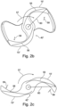
- One aspect is that a certain minimum proportion of the reinforcement elements/fibers in the expanded state of the rotor used in Figure 2b is shown, extends substantially stretched away from the axis of rotation. In the operating state corresponding to the third state and in Figure 2c is shown, these reinforcement elements/fibers are stretched and are also under tension created by the load of the pumped liquid.
- the proportion of reinforcement elements/fibers that satisfies the stated condition of the total amount of reinforcement elements/fibers embedded in the plastic of the rotor should be at least 30% or advantageously 50% or more advantageously, for example, represent 70%, measured as a percentage by volume or mass of the reinforcement elements/fibers or else in the number of reinforcement elements/fibers.
- a certain minimum length of the reinforcement elements/fibers is advantageously given, for example approximately at least 20% or at least 40% or 50% of the radius of the rotor.
- the reinforcing elements/fibers can easily change from the axial orientation, which corresponds to the direction of filling axially into the hub 43, to the radial position of the conveying elements 15 during the filling process of the mold, without being bent for this purpose, because the angle between the conveying element 15 and the hub 43 runs relatively flat with ⁇ 30° or preferably ⁇ 20°.
- the reinforcement elements/fibers are simply taken along by the matrix surrounding them and radially in accordance with the material flow in the conveying element Figure 2a aligned.
- reinforcement elements/fibers are a certain maximum thickness, with a maximum diameter of 40 ⁇ m being advantageous in order not to break the reinforcement elements/fibers themselves if the reinforcement elements/fibers are severely bent.
- the reinforcement elements/fibers are sufficiently rigid to bring the surrounding matrix back to its original state after deformation and to prevent sustained creeping of the matrix under permanent bending stress.
- reinforcement elements/fibers with a diameter of 40 ⁇ m are resistant to pressure and tension, so that when they are arranged outside the bending-neutral area, they also generate a restoring moment and counteract permanent deformation.
- the reinforcing elements/fibers may be coated with an adhesion promoter to improve bonding with the matrix.
- Figure 2b shows a cross-section of a rotor 42' with conveying elements 15', 15" in the relaxed, expanded state.
- the reinforcing elements/fibers 55, 56 have a shape that is as stretched as possible, so that their longitudinal rigidity resists further deformation of the rotor oppose
- the arrow 57 shows the direction of rotation of the rotor in the operating state.
- the arrows 58, 59 show the load acting on the conveying elements 15', 15'', ie the fluid counter-pressure acting on the conveying elements as a result of the conveying movement Figure 2b the chord 60 is drawn in, which designates the height of the conveying element 15' measured in the radial direction from the axis of rotation.
- the string 60 is also in Figure 2c drawn in, which shows the rotor 42' in the third state, the operating state.
- the reinforcing fibers 55, 56 are under tensile stress due to the load 58, 59 and absorb the expansion stresses in the conveying elements 15', 15''.
- the length of the chord 60, ie the height of the conveying elements, is constant or around in the operating state compared to the second state slightly increased but not decreased.
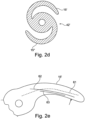
- Figure 2d shows the rotor 42' in compressed form, in which the conveying elements are folded onto the rotor hub. In this position, the pump can be brought to the place of operation through a narrow channel.
- FIG. 2e an operating state of the conveying element 15' is shown in cross section in more detail.
- the "bending-neutral fiber” or “bending-neutral area” is represented by the dashed line 61, ie the line or area which experiences neither an elongation nor a compression when the conveying element 15' is bent under load.
- a plurality of reinforcing fibers, designated 62, 63 by way of example, lie on the side of the line/area 61 on which a stretching stress arises in the operating state.
- the reinforcement elements/fibers are stretched there in sections and run straight and essentially parallel to the line/surface 61. In this way, they can absorb expansion stresses effectively.
- the rotor hub is in figure 3 denoted by 16, and the axis of rotation with 14. It is a plane 17 shown by means of a cut rectangle, wherein the plane 17 contains the axis of rotation 14, ie, the axis of rotation 14 runs completely in the Level 17. It should be noted that this representation is simplified, since the conveying elements are usually helical, so that the surface 17 is then no longer flat but curved.
- Two reinforcement elements/fibers 18 , 19 are shown as an example, both of which run in plane 17 essentially radially with respect to the axis of rotation 14 .
- the fiber 18 runs at an angle ⁇ to the axis of rotation 14, partially in the axial direction, the angle ⁇ advantageously being between 45° and 90°.
- the fiber 19 is aligned in such a way that it is perpendicular to the axis of rotation 14 .
- a real airfoil is helically curved in three dimensions, so that in many cases there is also a limited extension of the reinforcement elements/fibers in the azimuthal direction.
- the individual reinforcement elements/fibers do not have to be positioned in such a way that they have their first starting point/end point in the area of the axis of rotation 14 or the rotor hub 16 . They may also be arranged to extend between two endpoints that are both radially spaced from the rotor axis 14 and/or the rotor hub 16 . However, they can also extend from a first, radially outer blade edge up to a maximum of a second, radially opposite blade edge, at least across the axis.
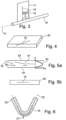
- FIG 4 a section 20 of a conveying element is shown schematically, the section 20 being cuboid in shape. In the section 20 a fiber 19 is shown.
- Figure 5b shows a side view, wherein the material of the section 20 is shown transparent, so that the course of the fiber 19 is visible approximately in the middle between the boundary surfaces of the conveying element.
- figure 6 shows the section 20 of the conveying element after a buckling.
- the fiber 19 is also deformed. Due to a certain inherent rigidity of the fiber, however, due to the resilience of the material of the conveying element, it can deviate outwards in the direction of arrow 21 when kinking, in order to achieve the largest possible radius of curvature of the fiber and thus counteract a break in the fiber. In the area of the kink, the fiber 19 is thus deflected from the center between the boundary walls of the conveying element for the duration of the kink.
- the central plane of the conveying element is represented at least in sections by a dashed line 22 .
- the plastic matrix of the rotor it is advantageous for the plastic matrix of the rotor to be soft, which corresponds to a Shore hardness of ⁇ 100 D, in particular ⁇ 80 D.
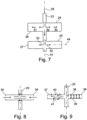
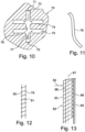
- FIG 7 a longitudinal section of the injection mold is shown, with the area that includes the volume of the rotor hub being denoted by 23 and the volumes of the individual conveying elements being denoted by 24, 25, 26, 27.
- an injection direction is also indicated by the arrow 28 .
- the further arrows 29, 30, 31, 32, 33 indicate that the injection molding material flows in axially along the axis of rotation 14 of the resulting rotor and from there radially outwards into the volumes of the conveying elements.
- the longitudinal axis of one of the conveying elements is indicated with a dot-dash line and is denoted by 44 . Be in the If a sufficient number of reinforcement elements/fibers of appropriate length are introduced into the injection molding material, they are oriented in the main direction of flow of the material and remain in place when the material solidifies.
- Displaced air and excess casting material can flow out through openings 45 at the radially outer end of the conveying elements.
- FIG 8 a reverse injection direction is indicated, with the injection molding material being injected radially inwards from the radially outer ends 34, 35 of the conveying elements towards the volume of the rotor 23.
- long reinforcement elements/fibers can be introduced, which are oriented and arranged in the manner intended according to the invention.
- the parts of the injection molding material that have escaped through the openings at the edges 40, 41 of the volumes of the conveyor elements in the injection mold can be removed, for example by cutting. Same can, as in figure 7 , take place at the outer edges of the conveying elements.
- FIG 10 1 is a schematic representation of an injection mold 70 having a first injection port 71 and a second injection port 72, the two injection ports 71, 72 being located at opposite ends of the central cavity 73 in which the potting forms the hub of the rotor.
- the cavities in which the conveying elements are formed are indicated only very schematically and are denoted by 74, 75.
- the arrows 76, 77 denote the directions of flow of the plastic flowing into the mold. If the plastic is injected into the mold one after the other or in changing proportions through the first injection opening 71 and the second injection opening 72, different flow directions of the liquid casting material result. If the reinforcement elements are added to this, different alignments of the reinforcement elements also result accordingly in the resulting rotor. In this way, different alignment patterns can be designed by controlling the injection speed through the injection ports and changing the injection speeds or the ratio of the injection speeds through the different injection ports during the molding process.
- a reinforcing element in the form of a metal foil or a plastic foil 78 is shown in a perspective view, which can be, for example, only a few micrometers thick, a few tenths of a millimeter wide and a few millimeters long.
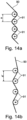
- figure 12 1 shows, as a reinforcing element, an elongate strip of fabric which schematically has only two fibers 79, 80 running in the longitudinal direction and a large number of shorter fibers 81 running transversely thereto.
- Such a fabric can absorb tensile forces particularly well in the two longitudinal directions of the fibers present.
- a region of a conveying element 82 is shown schematically in cross section.
- 83 designates the surface which is on the pressure side during operation and which is exposed to the counter-pressure of the fluid, indicated by arrow 84 .
- top surface opposite this side or top surface 83 is denoted by 85 .
- a coating 86 is provided on this side of the conveying element 82, which can be provided by an adhesive film or a liquid coating, for example paint.
- the “fiber” or surface that is mechanically neutral when the conveying element 82 bends during pumping operation is drawn in as a dashed line and is denoted by 87 .
- the reinforcement elements 88 are already prestressed by internal material stress. This is achieved in that, after the rotor has been produced, more precisely after completion of the injection molding process, the conveying element is either stretched on the side of the cover surface 83 or shrunk on the side of the cover surface 85 .
- the radiation crosslinking can also be introduced, for example, by means of one or more laser beams and can thus be applied locally in a very focused manner.
- the material of the conveying element 82 is shrunk on the side of the neutral surface of the fiber 87, which faces the cover layer 85, for example by heat treatment or by crosslinking/polymerization, which does not take place or only to a lesser extent on the other side of the conveying element.
- a fabric made of fibers is shown as an example.
- the fiber 90 runs as part of a fiber bundle at an angle to other fiber bundles 91, the fiber bundles 91 being arranged perpendicularly to the drawing surface and being alternately passed by the fiber 90 on the left and right side.
- the fiber bundles 91 In 14a , which represents the relaxed state of the rotor, the fiber bundles 91 have a distance a from one another and the fiber 90 has a back and forth curved course.
- Figure 14b which represents the state of the rotor in operation, the fiber bundles 91 have a greater distance a' from one another and the fiber 90 has a less curved course.
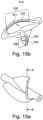
- Figure 15a shows a rotor in an expanded, force-free state in a perspective view and the identification of a sectional plane AA.
- Figure 15b shows the same rotor in the same sectional view.
- the dashed lines 101 and 102 represent the bending-neutral fiber or surface of the respective airfoil.
- the fibers 103 and 104 show an example of the course of two fibers in the section plane shown. The fibers are curved in this state. In the operating state under load, the fluid exerts a pressure on the blade blades in the direction of the arrows shown, as a result of which they stand up further.
- the fibers 103 and 104 are stretched at least in the areas marked 105 and 106, which hinders further lifting of the airfoils, since the fibers, which are very stiff in tension, would then have to be stretched in their axial extent.
- the advantage of such a design is that the shape of the airfoil is almost constant above a minimum speed.
- FIG. 16a shows a rotor in an expanded, force-free state in a perspective view and the marking of a sectional plane BB.
- Figure 16b shows the same rotor in the same sectional view.
- the dashed lines 111 and 112 represent the bending-neutral fiber or surface of the respective airfoil.
- the fibers 113 and 114 show an example of the course of two fibers in the section plane shown. As can be seen, the fibers in this example are already stretched over a wide area. Since the fibers are very stiff, further stretching of the fibers is hardly possible.
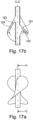
- Figure 17a shows a rotor in an expanded, force-free state in a side view showing a sectional plane CC.
- Figure 17b shows the same rotor in the same sectional view.
- the dashed lines 121 and 122 represent the bending-neutral fiber or surface of the respective airfoil.
- the fibers 123 and 124 show an example of the course of two fibers in the section plane shown. As can be seen, the fibers in this example are already stretched over a wide area. Since the fibers are very stiff, further stretching of the fibers is hardly possible. Also under the forces occurring in the operating state, which act on the blades due to the flow pressure and which in the Figure 17b are represented by arrows, such an airfoil will no longer deform significantly.
Landscapes
- Health & Medical Sciences (AREA)
- Engineering & Computer Science (AREA)
- Heart & Thoracic Surgery (AREA)
- Mechanical Engineering (AREA)
- Cardiology (AREA)
- General Health & Medical Sciences (AREA)
- Veterinary Medicine (AREA)
- Hematology (AREA)
- Life Sciences & Earth Sciences (AREA)
- Animal Behavior & Ethology (AREA)
- Anesthesiology (AREA)
- Public Health (AREA)
- Biomedical Technology (AREA)
- Vascular Medicine (AREA)
- Manufacturing & Machinery (AREA)
- General Engineering & Computer Science (AREA)
- Transplantation (AREA)
- Structures Of Non-Positive Displacement Pumps (AREA)
- Details And Applications Of Rotary Liquid Pumps (AREA)
- External Artificial Organs (AREA)
- Rotary Pumps (AREA)
Priority Applications (1)
| Application Number | Priority Date | Filing Date | Title |
|---|---|---|---|
| EP23153829.9A EP4194045A1 (de) | 2015-04-30 | 2016-04-29 | Rotor für eine fluidpumpe |
Applications Claiming Priority (3)
| Application Number | Priority Date | Filing Date | Title |
|---|---|---|---|
| EP15166045.3A EP3088018A1 (de) | 2015-04-30 | 2015-04-30 | Rotor für eine fluidpumpe sowie verfahren und giessform für seine herstellung |
| EP15166042.0A EP3088017A1 (de) | 2015-04-30 | 2015-04-30 | Rotor für eine fluidpumpe sowie verfahren und giessform für seine herstellung |
| PCT/EP2016/059708 WO2016174257A1 (de) | 2015-04-30 | 2016-04-29 | Rotor für eine fluidpumpe sowie verfahren und giessform für seine herstellung |
Related Child Applications (2)
| Application Number | Title | Priority Date | Filing Date |
|---|---|---|---|
| EP23153829.9A Division-Into EP4194045A1 (de) | 2015-04-30 | 2016-04-29 | Rotor für eine fluidpumpe |
| EP23153829.9A Division EP4194045A1 (de) | 2015-04-30 | 2016-04-29 | Rotor für eine fluidpumpe |
Publications (2)
| Publication Number | Publication Date |
|---|---|
| EP3288609A1 EP3288609A1 (de) | 2018-03-07 |
| EP3288609B1 true EP3288609B1 (de) | 2023-03-15 |
Family
ID=55860873
Family Applications (2)
| Application Number | Title | Priority Date | Filing Date |
|---|---|---|---|
| EP16719427.3A Active EP3288609B1 (de) | 2015-04-30 | 2016-04-29 | Rotor für eine fluidpumpe |
| EP23153829.9A Pending EP4194045A1 (de) | 2015-04-30 | 2016-04-29 | Rotor für eine fluidpumpe |
Family Applications After (1)
| Application Number | Title | Priority Date | Filing Date |
|---|---|---|---|
| EP23153829.9A Pending EP4194045A1 (de) | 2015-04-30 | 2016-04-29 | Rotor für eine fluidpumpe |
Country Status (10)
| Country | Link |
|---|---|
| US (2) | US10801511B2 (da) |
| EP (2) | EP3288609B1 (da) |
| JP (3) | JP7088674B2 (da) |
| KR (1) | KR20180002662A (da) |
| CN (1) | CN107548309A (da) |
| CA (1) | CA2980950A1 (da) |
| DK (1) | DK3288609T3 (da) |
| ES (1) | ES2942884T3 (da) |
| HK (1) | HK1245164A1 (da) |
| WO (1) | WO2016174257A1 (da) |
Families Citing this family (19)
| Publication number | Priority date | Publication date | Assignee | Title |
|---|---|---|---|---|
| CN108742951B (zh) | 2012-06-06 | 2021-05-25 | 洋红医疗有限公司 | 人工肾脏瓣膜 |
| CN105473063B (zh) | 2013-03-13 | 2019-03-08 | 马真塔医药有限公司 | 血液泵浦及其制造方法 |
| US10583231B2 (en) | 2013-03-13 | 2020-03-10 | Magenta Medical Ltd. | Blood pump |
| US11291824B2 (en) | 2015-05-18 | 2022-04-05 | Magenta Medical Ltd. | Blood pump |
| EP3518825B1 (en) | 2016-09-29 | 2020-05-27 | Magenta Medical Ltd. | Blood vessel tube |
| EP3532120B1 (en) | 2016-10-25 | 2024-05-01 | Magenta Medical Ltd. | Ventricular assist device |
| JP7094279B2 (ja) | 2016-11-23 | 2022-07-01 | マジェンタ・メディカル・リミテッド | 血液ポンプ |
| CA3066361A1 (en) | 2017-06-07 | 2018-12-13 | Shifamed Holdings, Llc | Intravascular fluid movement devices, systems, and methods of use |
| EP3710076B1 (en) | 2017-11-13 | 2023-12-27 | Shifamed Holdings, LLC | Intravascular fluid movement devices, systems, and methods of use |
| US10905808B2 (en) | 2018-01-10 | 2021-02-02 | Magenta Medical Ltd. | Drive cable for use with a blood pump |
| EP3693038B1 (en) | 2018-01-10 | 2024-06-05 | Magenta Medical Ltd. | Ventricular assist device |
| US10722631B2 (en) | 2018-02-01 | 2020-07-28 | Shifamed Holdings, Llc | Intravascular blood pumps and methods of use and manufacture |
| US10893927B2 (en) | 2018-03-29 | 2021-01-19 | Magenta Medical Ltd. | Inferior vena cava blood-flow implant |
| EP3782665B1 (en) | 2019-01-24 | 2021-08-25 | Magenta Medical Ltd. | Ventricular assist device |
| JP2022540616A (ja) | 2019-07-12 | 2022-09-16 | シファメド・ホールディングス・エルエルシー | 血管内血液ポンプならびに製造および使用の方法 |
| US11654275B2 (en) | 2019-07-22 | 2023-05-23 | Shifamed Holdings, Llc | Intravascular blood pumps with struts and methods of use and manufacture |
| US11724089B2 (en) | 2019-09-25 | 2023-08-15 | Shifamed Holdings, Llc | Intravascular blood pump systems and methods of use and control thereof |
| DE102020102474A1 (de) | 2020-01-31 | 2021-08-05 | Kardion Gmbh | Pumpe zum Fördern eines Fluids und Verfahren zum Herstellen einer Pumpe |
| CA3176272A1 (en) * | 2020-04-07 | 2021-10-14 | Magenta Medical Ltd | Ventricular assist device |
Family Cites Families (16)
| Publication number | Priority date | Publication date | Assignee | Title |
|---|---|---|---|---|
| JPH0771804B2 (ja) * | 1990-10-12 | 1995-08-02 | 株式会社神戸製鋼所 | 炭素繊維プリプレグ及び炭素繊維強化樹脂 |
| JPH09217601A (ja) * | 1996-02-13 | 1997-08-19 | Ishikawajima Harima Heavy Ind Co Ltd | 繊維強化複合材製翼車 |
| WO2001043952A1 (en) * | 1999-12-15 | 2001-06-21 | N.V. Bekaert S.A. | A reinforcing structure for stiff composite articles |
| US7393181B2 (en) * | 2004-09-17 | 2008-07-01 | The Penn State Research Foundation | Expandable impeller pump |
| EP2194278A1 (de) | 2008-12-05 | 2010-06-09 | ECP Entwicklungsgesellschaft mbH | Fluidpumpe mit einem rotor |
| EP2229965A1 (de) * | 2009-03-18 | 2010-09-22 | ECP Entwicklungsgesellschaft mbH | Fluidpumpe mit besonderer Gestaltung eines Rotorblattes |
| DE102009036018A1 (de) | 2009-08-04 | 2011-02-17 | Siemens Aktiengesellschaft | Thermoplastendstufenschaufel |
| FR2954271B1 (fr) | 2009-12-21 | 2012-02-17 | Snecma | Pale d'helice d'aeronef |
| FR2962175B1 (fr) | 2010-07-02 | 2012-08-10 | Snecma | Aube a longeron composite integre |
| EP2407187A3 (de) * | 2010-07-15 | 2012-06-20 | ECP Entwicklungsgesellschaft mbH | Blutpumpe für die invasive Anwendung innerhalb eines Körpers eines Patienten |
| EP2407186A1 (de) * | 2010-07-15 | 2012-01-18 | ECP Entwicklungsgesellschaft mbH | Rotor für eine Pumpe, hergestellt mit einem ersten, elastischen Werkstoff |
| EP2407185A1 (de) | 2010-07-15 | 2012-01-18 | ECP Entwicklungsgesellschaft mbH | Radial komprimierbarer und expandierbarer Rotor für eine Pumpe mit einem Schaufelblatt |
| EP2607712B1 (de) * | 2011-12-22 | 2016-07-13 | ECP Entwicklungsgesellschaft mbH | Pumpengehäuse mit einem Innenraum zur Aufnahme eines Pumpenrotors |
| EP2692369B1 (en) | 2012-07-31 | 2015-04-15 | Rheinisch-Westfälische Technische Hochschule Aachen | Axial flow blood pump device |
| US10414487B2 (en) | 2013-07-08 | 2019-09-17 | Safran Aircraft Engines | Composite propeller blade for an aircraft |
| EP3088018A1 (de) * | 2015-04-30 | 2016-11-02 | ECP Entwicklungsgesellschaft mbH | Rotor für eine fluidpumpe sowie verfahren und giessform für seine herstellung |
-
2016
- 2016-04-29 EP EP16719427.3A patent/EP3288609B1/de active Active
- 2016-04-29 CN CN201680025056.XA patent/CN107548309A/zh active Pending
- 2016-04-29 KR KR1020177031993A patent/KR20180002662A/ko active IP Right Grant
- 2016-04-29 CA CA2980950A patent/CA2980950A1/en active Pending
- 2016-04-29 WO PCT/EP2016/059708 patent/WO2016174257A1/de active Application Filing
- 2016-04-29 US US15/570,128 patent/US10801511B2/en active Active
- 2016-04-29 DK DK16719427.3T patent/DK3288609T3/da active
- 2016-04-29 JP JP2017556822A patent/JP7088674B2/ja active Active
- 2016-04-29 ES ES16719427T patent/ES2942884T3/es active Active
- 2016-04-29 EP EP23153829.9A patent/EP4194045A1/de active Pending
-
2018
- 2018-04-10 HK HK18104689.8A patent/HK1245164A1/zh unknown
-
2020
- 2020-09-01 US US17/008,873 patent/US20210054848A1/en active Pending
-
2022
- 2022-06-09 JP JP2022093553A patent/JP7425828B2/ja active Active
-
2024
- 2024-01-19 JP JP2024006787A patent/JP2024026879A/ja active Pending
Also Published As
| Publication number | Publication date |
|---|---|
| CN107548309A (zh) | 2018-01-05 |
| JP7425828B2 (ja) | 2024-01-31 |
| EP4194045A1 (de) | 2023-06-14 |
| WO2016174257A1 (de) | 2016-11-03 |
| EP3288609A1 (de) | 2018-03-07 |
| US20210054848A1 (en) | 2021-02-25 |
| JP2022111320A (ja) | 2022-07-29 |
| JP2018522608A (ja) | 2018-08-16 |
| JP7088674B2 (ja) | 2022-06-21 |
| CA2980950A1 (en) | 2016-11-03 |
| KR20180002662A (ko) | 2018-01-08 |
| US20180149165A1 (en) | 2018-05-31 |
| HK1245164A1 (zh) | 2018-08-24 |
| DK3288609T3 (da) | 2023-05-01 |
| JP2024026879A (ja) | 2024-02-28 |
| ES2942884T3 (es) | 2023-06-07 |
| US10801511B2 (en) | 2020-10-13 |
Similar Documents
| Publication | Publication Date | Title |
|---|---|---|
| EP3288609B1 (de) | Rotor für eine fluidpumpe | |
| EP3288608A1 (de) | Rotor für eine fluidpumpe sowie verfahren und giessform für seine herstellung | |
| EP2229965A1 (de) | Fluidpumpe mit besonderer Gestaltung eines Rotorblattes | |
| DE112011102353T5 (de) | Radial komprimierbarer und expandierbarer Rotor für eine Pumpe mit einem Schaufelblatt | |
| EP2909015B1 (de) | System und verfahren zum herstellen eines rotorblattgurtes | |
| DE112021000911T5 (de) | Intravaskuläre blutpumpe mit einlassfilter | |
| DE112010002711T5 (de) | Komprimierbares und expandierbares Schaufelblatt für eine Fluidpumpe | |
| DE112012003569T5 (de) | Entfaltbare Gefäßpumpe | |
| EP2666615B1 (de) | Verfahren zur Herstellung einer Windenergieanlagenrotorblatthalbschale bzw. eines Windenergieanlagenrotorblatts und Herstellungsform zu diesem Zweck | |
| EP3018342B1 (de) | Verfahren zum herstellen eines rotorblatts einer windenergieanlage | |
| DE102016009640A1 (de) | Gurt aus vorgefertigten Elementen mit Gelege und ein Verfahren zu seiner Fertigung | |
| EP2298372A1 (de) | Rotor für eine Axialpumpe zur Förderung eines Fluids | |
| EP2329139B1 (de) | Rotorblatt mit einem gurt mit einer in längsrichtung abnehmenden breite, verfahren zur herstellung des rotorblattes und verlegehilfe für gelegebänder des gurtes | |
| EP3486476B1 (de) | Steg für ein rotorblatt einer windenergieanlage und verfahren zum herstellen eines stegs | |
| EP3551438B1 (de) | Hinterkantengurt eines rotorblatts einer windenergieanlage, rotorblatt und verfahren zum herstellen eines hinterkantengurts | |
| EP3360667A1 (de) | Rotorblatthinterkanten-verklebewinkel | |
| EP3252303A1 (de) | Verfahren zur bestimmung einer positionierung eines rotorblattgurtes, rotorblatt und windenergieanlage | |
| WO2009133130A1 (de) | Giessvorrichtung zur herstellung hohler gussgegenstände mit nicht-rotationssymmetrischem projektil | |
| EP3088017A1 (de) | Rotor für eine fluidpumpe sowie verfahren und giessform für seine herstellung | |
| DE102010036408A1 (de) | Fläche zum Anordnen in einem strömenden Fluid, Verwendung einer solchen Fläche sowie ein Verfahren zum Reduzieren eines Strömungswiderstandes | |
| DE102009046891A1 (de) | Polymerstent |
Legal Events
| Date | Code | Title | Description |
|---|---|---|---|
| STAA | Information on the status of an ep patent application or granted ep patent |
Free format text: STATUS: THE INTERNATIONAL PUBLICATION HAS BEEN MADE |
|
| PUAI | Public reference made under article 153(3) epc to a published international application that has entered the european phase |
Free format text: ORIGINAL CODE: 0009012 |
|
| STAA | Information on the status of an ep patent application or granted ep patent |
Free format text: STATUS: REQUEST FOR EXAMINATION WAS MADE |
|
| 17P | Request for examination filed |
Effective date: 20171129 |
|
| AK | Designated contracting states |
Kind code of ref document: A1 Designated state(s): AL AT BE BG CH CY CZ DE DK EE ES FI FR GB GR HR HU IE IS IT LI LT LU LV MC MK MT NL NO PL PT RO RS SE SI SK SM TR |
|
| AX | Request for extension of the european patent |
Extension state: BA ME |
|
| DAV | Request for validation of the european patent (deleted) | ||
| DAX | Request for extension of the european patent (deleted) | ||
| REG | Reference to a national code |
Ref country code: DE Ref legal event code: R079 Ref document number: 502016015636 Country of ref document: DE Free format text: PREVIOUS MAIN CLASS: A61M0001100000 Ipc: A61M0060130000 Ref country code: DE Ref legal event code: R079 Free format text: PREVIOUS MAIN CLASS: A61M0001100000 Ipc: A61M0060130000 |
|
| GRAP | Despatch of communication of intention to grant a patent |
Free format text: ORIGINAL CODE: EPIDOSNIGR1 |
|
| STAA | Information on the status of an ep patent application or granted ep patent |
Free format text: STATUS: GRANT OF PATENT IS INTENDED |
|
| INTG | Intention to grant announced |
Effective date: 20220407 |
|
| RIC1 | Information provided on ipc code assigned before grant |
Ipc: A61M 60/81 20210101ALI20220325BHEP Ipc: A61M 60/808 20210101ALI20220325BHEP Ipc: A61M 60/414 20210101ALI20220325BHEP Ipc: A61M 60/237 20210101ALI20220325BHEP Ipc: A61M 60/226 20210101ALI20220325BHEP Ipc: A61M 60/13 20210101AFI20220325BHEP |
|
| GRAJ | Information related to disapproval of communication of intention to grant by the applicant or resumption of examination proceedings by the epo deleted |
Free format text: ORIGINAL CODE: EPIDOSDIGR1 |
|
| STAA | Information on the status of an ep patent application or granted ep patent |
Free format text: STATUS: REQUEST FOR EXAMINATION WAS MADE |
|
| GRAP | Despatch of communication of intention to grant a patent |
Free format text: ORIGINAL CODE: EPIDOSNIGR1 |
|
| STAA | Information on the status of an ep patent application or granted ep patent |
Free format text: STATUS: GRANT OF PATENT IS INTENDED |
|
| INTC | Intention to grant announced (deleted) | ||
| INTG | Intention to grant announced |
Effective date: 20220920 |
|
| GRAS | Grant fee paid |
Free format text: ORIGINAL CODE: EPIDOSNIGR3 |
|
| GRAA | (expected) grant |
Free format text: ORIGINAL CODE: 0009210 |
|
| STAA | Information on the status of an ep patent application or granted ep patent |
Free format text: STATUS: THE PATENT HAS BEEN GRANTED |
|
| RAP3 | Party data changed (applicant data changed or rights of an application transferred) |
Owner name: ECP ENTWICKLUNGSGESELLSCHAFT MBH |
|
| AK | Designated contracting states |
Kind code of ref document: B1 Designated state(s): AL AT BE BG CH CY CZ DE DK EE ES FI FR GB GR HR HU IE IS IT LI LT LU LV MC MK MT NL NO PL PT RO RS SE SI SK SM TR |
|
| REG | Reference to a national code |
Ref country code: CH Ref legal event code: EP Ref country code: GB Ref legal event code: FG4D Free format text: NOT ENGLISH |
|
| REG | Reference to a national code |
Ref country code: DE Ref legal event code: R096 Ref document number: 502016015636 Country of ref document: DE |
|
| REG | Reference to a national code |
Ref country code: IE Ref legal event code: FG4D Free format text: LANGUAGE OF EP DOCUMENT: GERMAN |
|
| REG | Reference to a national code |
Ref country code: AT Ref legal event code: REF Ref document number: 1553638 Country of ref document: AT Kind code of ref document: T Effective date: 20230415 |
|
| REG | Reference to a national code |
Ref country code: DK Ref legal event code: T3 Effective date: 20230426 |
|
| REG | Reference to a national code |
Ref country code: NL Ref legal event code: FP |
|
| REG | Reference to a national code |
Ref country code: SE Ref legal event code: TRGR |
|
| REG | Reference to a national code |
Ref country code: ES Ref legal event code: FG2A Ref document number: 2942884 Country of ref document: ES Kind code of ref document: T3 Effective date: 20230607 |
|
| P01 | Opt-out of the competence of the unified patent court (upc) registered |
Effective date: 20230526 |
|
| REG | Reference to a national code |
Ref country code: LT Ref legal event code: MG9D |
|
| PG25 | Lapsed in a contracting state [announced via postgrant information from national office to epo] |
Ref country code: RS Free format text: LAPSE BECAUSE OF FAILURE TO SUBMIT A TRANSLATION OF THE DESCRIPTION OR TO PAY THE FEE WITHIN THE PRESCRIBED TIME-LIMIT Effective date: 20230315 Ref country code: NO Free format text: LAPSE BECAUSE OF FAILURE TO SUBMIT A TRANSLATION OF THE DESCRIPTION OR TO PAY THE FEE WITHIN THE PRESCRIBED TIME-LIMIT Effective date: 20230615 Ref country code: LV Free format text: LAPSE BECAUSE OF FAILURE TO SUBMIT A TRANSLATION OF THE DESCRIPTION OR TO PAY THE FEE WITHIN THE PRESCRIBED TIME-LIMIT Effective date: 20230315 Ref country code: LT Free format text: LAPSE BECAUSE OF FAILURE TO SUBMIT A TRANSLATION OF THE DESCRIPTION OR TO PAY THE FEE WITHIN THE PRESCRIBED TIME-LIMIT Effective date: 20230315 Ref country code: HR Free format text: LAPSE BECAUSE OF FAILURE TO SUBMIT A TRANSLATION OF THE DESCRIPTION OR TO PAY THE FEE WITHIN THE PRESCRIBED TIME-LIMIT Effective date: 20230315 |
|
| PGFP | Annual fee paid to national office [announced via postgrant information from national office to epo] |
Ref country code: IT Payment date: 20230428 Year of fee payment: 8 Ref country code: FR Payment date: 20230427 Year of fee payment: 8 Ref country code: ES Payment date: 20230501 Year of fee payment: 8 Ref country code: DK Payment date: 20230427 Year of fee payment: 8 Ref country code: DE Payment date: 20230321 Year of fee payment: 8 Ref country code: CH Payment date: 20230502 Year of fee payment: 8 |
|
| PG25 | Lapsed in a contracting state [announced via postgrant information from national office to epo] |
Ref country code: GR Free format text: LAPSE BECAUSE OF FAILURE TO SUBMIT A TRANSLATION OF THE DESCRIPTION OR TO PAY THE FEE WITHIN THE PRESCRIBED TIME-LIMIT Effective date: 20230616 Ref country code: FI Free format text: LAPSE BECAUSE OF FAILURE TO SUBMIT A TRANSLATION OF THE DESCRIPTION OR TO PAY THE FEE WITHIN THE PRESCRIBED TIME-LIMIT Effective date: 20230315 |
|
| PGFP | Annual fee paid to national office [announced via postgrant information from national office to epo] |
Ref country code: SE Payment date: 20230511 Year of fee payment: 8 |
|
| PG25 | Lapsed in a contracting state [announced via postgrant information from national office to epo] |
Ref country code: SM Free format text: LAPSE BECAUSE OF FAILURE TO SUBMIT A TRANSLATION OF THE DESCRIPTION OR TO PAY THE FEE WITHIN THE PRESCRIBED TIME-LIMIT Effective date: 20230315 Ref country code: RO Free format text: LAPSE BECAUSE OF FAILURE TO SUBMIT A TRANSLATION OF THE DESCRIPTION OR TO PAY THE FEE WITHIN THE PRESCRIBED TIME-LIMIT Effective date: 20230315 Ref country code: PT Free format text: LAPSE BECAUSE OF FAILURE TO SUBMIT A TRANSLATION OF THE DESCRIPTION OR TO PAY THE FEE WITHIN THE PRESCRIBED TIME-LIMIT Effective date: 20230717 Ref country code: EE Free format text: LAPSE BECAUSE OF FAILURE TO SUBMIT A TRANSLATION OF THE DESCRIPTION OR TO PAY THE FEE WITHIN THE PRESCRIBED TIME-LIMIT Effective date: 20230315 Ref country code: CZ Free format text: LAPSE BECAUSE OF FAILURE TO SUBMIT A TRANSLATION OF THE DESCRIPTION OR TO PAY THE FEE WITHIN THE PRESCRIBED TIME-LIMIT Effective date: 20230315 |
|
| PG25 | Lapsed in a contracting state [announced via postgrant information from national office to epo] |
Ref country code: SK Free format text: LAPSE BECAUSE OF FAILURE TO SUBMIT A TRANSLATION OF THE DESCRIPTION OR TO PAY THE FEE WITHIN THE PRESCRIBED TIME-LIMIT Effective date: 20230315 Ref country code: PL Free format text: LAPSE BECAUSE OF FAILURE TO SUBMIT A TRANSLATION OF THE DESCRIPTION OR TO PAY THE FEE WITHIN THE PRESCRIBED TIME-LIMIT Effective date: 20230315 Ref country code: IS Free format text: LAPSE BECAUSE OF FAILURE TO SUBMIT A TRANSLATION OF THE DESCRIPTION OR TO PAY THE FEE WITHIN THE PRESCRIBED TIME-LIMIT Effective date: 20230715 |
|
| REG | Reference to a national code |
Ref country code: DE Ref legal event code: R097 Ref document number: 502016015636 Country of ref document: DE |
|
| PG25 | Lapsed in a contracting state [announced via postgrant information from national office to epo] |
Ref country code: LU Free format text: LAPSE BECAUSE OF NON-PAYMENT OF DUE FEES Effective date: 20230429 |
|
| REG | Reference to a national code |
Ref country code: BE Ref legal event code: MM Effective date: 20230430 |
|
| PG25 | Lapsed in a contracting state [announced via postgrant information from national office to epo] |
Ref country code: MC Free format text: LAPSE BECAUSE OF FAILURE TO SUBMIT A TRANSLATION OF THE DESCRIPTION OR TO PAY THE FEE WITHIN THE PRESCRIBED TIME-LIMIT Effective date: 20230315 |
|
| PLBE | No opposition filed within time limit |
Free format text: ORIGINAL CODE: 0009261 |
|
| STAA | Information on the status of an ep patent application or granted ep patent |
Free format text: STATUS: NO OPPOSITION FILED WITHIN TIME LIMIT |
|
| PG25 | Lapsed in a contracting state [announced via postgrant information from national office to epo] |
Ref country code: SI Free format text: LAPSE BECAUSE OF FAILURE TO SUBMIT A TRANSLATION OF THE DESCRIPTION OR TO PAY THE FEE WITHIN THE PRESCRIBED TIME-LIMIT Effective date: 20230315 Ref country code: MC Free format text: LAPSE BECAUSE OF FAILURE TO SUBMIT A TRANSLATION OF THE DESCRIPTION OR TO PAY THE FEE WITHIN THE PRESCRIBED TIME-LIMIT Effective date: 20230315 |
|
| 26N | No opposition filed |
Effective date: 20231218 |
|
| PG25 | Lapsed in a contracting state [announced via postgrant information from national office to epo] |
Ref country code: BE Free format text: LAPSE BECAUSE OF NON-PAYMENT OF DUE FEES Effective date: 20230430 |
|
| PGFP | Annual fee paid to national office [announced via postgrant information from national office to epo] |
Ref country code: NL Payment date: 20240320 Year of fee payment: 9 Ref country code: IE Payment date: 20240322 Year of fee payment: 9 |
|
| PGFP | Annual fee paid to national office [announced via postgrant information from national office to epo] |
Ref country code: GB Payment date: 20240321 Year of fee payment: 9 |