EP3288317B1 - Verfahren und vorrichtung zur überwachung und übertragung von downlink-planungsdaten - Google Patents
Verfahren und vorrichtung zur überwachung und übertragung von downlink-planungsdaten Download PDFInfo
- Publication number
- EP3288317B1 EP3288317B1 EP16795711.7A EP16795711A EP3288317B1 EP 3288317 B1 EP3288317 B1 EP 3288317B1 EP 16795711 A EP16795711 A EP 16795711A EP 3288317 B1 EP3288317 B1 EP 3288317B1
- Authority
- EP
- European Patent Office
- Prior art keywords
- terminal
- sending
- monitoring cycle
- base station
- drx monitoring
- Prior art date
- Legal status (The legal status is an assumption and is not a legal conclusion. Google has not performed a legal analysis and makes no representation as to the accuracy of the status listed.)
- Active
Links
Images


Classifications
-
- H—ELECTRICITY
- H04—ELECTRIC COMMUNICATION TECHNIQUE
- H04W—WIRELESS COMMUNICATION NETWORKS
- H04W24/00—Supervisory, monitoring or testing arrangements
- H04W24/02—Arrangements for optimising operational condition
-
- H—ELECTRICITY
- H04—ELECTRIC COMMUNICATION TECHNIQUE
- H04W—WIRELESS COMMUNICATION NETWORKS
- H04W52/00—Power management, e.g. Transmission Power Control [TPC] or power classes
- H04W52/02—Power saving arrangements
- H04W52/0209—Power saving arrangements in terminal devices
- H04W52/0225—Power saving arrangements in terminal devices using monitoring of external events, e.g. the presence of a signal
-
- H—ELECTRICITY
- H04—ELECTRIC COMMUNICATION TECHNIQUE
- H04W—WIRELESS COMMUNICATION NETWORKS
- H04W52/00—Power management, e.g. Transmission Power Control [TPC] or power classes
- H04W52/02—Power saving arrangements
- H04W52/0203—Power saving arrangements in the radio access network or backbone network of wireless communication networks
- H04W52/0206—Power saving arrangements in the radio access network or backbone network of wireless communication networks in access points, e.g. base stations
-
- H—ELECTRICITY
- H04—ELECTRIC COMMUNICATION TECHNIQUE
- H04W—WIRELESS COMMUNICATION NETWORKS
- H04W52/00—Power management, e.g. Transmission Power Control [TPC] or power classes
- H04W52/02—Power saving arrangements
- H04W52/0209—Power saving arrangements in terminal devices
- H04W52/0212—Power saving arrangements in terminal devices managed by the network, e.g. network or access point is leader and terminal is follower
- H04W52/0216—Power saving arrangements in terminal devices managed by the network, e.g. network or access point is leader and terminal is follower using a pre-established activity schedule, e.g. traffic indication frame
-
- H—ELECTRICITY
- H04—ELECTRIC COMMUNICATION TECHNIQUE
- H04W—WIRELESS COMMUNICATION NETWORKS
- H04W52/00—Power management, e.g. Transmission Power Control [TPC] or power classes
- H04W52/02—Power saving arrangements
- H04W52/0209—Power saving arrangements in terminal devices
- H04W52/0225—Power saving arrangements in terminal devices using monitoring of external events, e.g. the presence of a signal
- H04W52/0248—Power saving arrangements in terminal devices using monitoring of external events, e.g. the presence of a signal dependent on the time of the day, e.g. according to expected transmission activity
-
- H—ELECTRICITY
- H04—ELECTRIC COMMUNICATION TECHNIQUE
- H04W—WIRELESS COMMUNICATION NETWORKS
- H04W72/00—Local resource management
- H04W72/12—Wireless traffic scheduling
-
- H—ELECTRICITY
- H04—ELECTRIC COMMUNICATION TECHNIQUE
- H04W—WIRELESS COMMUNICATION NETWORKS
- H04W76/00—Connection management
- H04W76/20—Manipulation of established connections
- H04W76/28—Discontinuous transmission [DTX]; Discontinuous reception [DRX]
-
- Y—GENERAL TAGGING OF NEW TECHNOLOGICAL DEVELOPMENTS; GENERAL TAGGING OF CROSS-SECTIONAL TECHNOLOGIES SPANNING OVER SEVERAL SECTIONS OF THE IPC; TECHNICAL SUBJECTS COVERED BY FORMER USPC CROSS-REFERENCE ART COLLECTIONS [XRACs] AND DIGESTS
- Y02—TECHNOLOGIES OR APPLICATIONS FOR MITIGATION OR ADAPTATION AGAINST CLIMATE CHANGE
- Y02D—CLIMATE CHANGE MITIGATION TECHNOLOGIES IN INFORMATION AND COMMUNICATION TECHNOLOGIES [ICT], I.E. INFORMATION AND COMMUNICATION TECHNOLOGIES AIMING AT THE REDUCTION OF THEIR OWN ENERGY USE
- Y02D30/00—Reducing energy consumption in communication networks
- Y02D30/70—Reducing energy consumption in communication networks in wireless communication networks
Definitions
- the present invention relates to the field of communications technologies, and in particular, to a downlink scheduling data monitoring method, a downlink scheduling data sending method, and an apparatus.
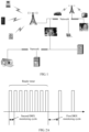
- the M2M communications system is a network-based system architecture focusing on intelligent interaction between devices.
- An M2M technology provides a means of real-time data transmission between systems, remote devices, and/or individuals, and a wireless communications module is built inside a device in the M2M communications system, to implement functions such as performing monitoring, commanding and dispatching, data collection, and measurement on the device.
- US 2011/039536 A1 describes systems and methods for receiving data from a radio network by a terminal.
- the therein described methods include: receiving downlink data while the terminal operates according to a first discontinuous period; transmitting a response message with respect to the downlink data; and operating according to a second discontinuous period after transmitting the response message.
- US 2014/307606 A1 describes methods and apparatus for controlling discontinuous reception on a mobile device and in particular to control a short discontinuous reception timer in response to receipt of a medium access control control element. The therein described methods and apparatus include stopping, restarting or maintaining the short discontinuous reception timer.
- US 2013/223307 A1 describes systems and methods for operating a base station node of a radio access network.
- the therein described method comprises communicating information over a radio interface between the base station node and a wireless terminal which operates with discontinuous reception.
- the M2M communications system is widely applied to many scenarios, such as smart metering, environment monitoring, and remote monitoring.
- a device in the M2M communications system needs to periodically monitor and report use of water, electricity, and gas.
- the device remotely cuts off energy supply, and may update subscription information after a house tenant changes.
- the device in the M2M communications system needs to monitor downlink scheduling data, and the device in the M2M communications system is powered by a battery. If the device is always in a state of monitoring the downlink scheduling data, power consumption of the device is relatively large; or if the device is always in a state of not monitoring the downlink scheduling data, the downlink scheduling data cannot be received in a timely manner.
- monitoring of downlink scheduling data it is apparently inappropriate to consider only timely receiving of the downlink scheduling data without considering power consumption of a device. Likewise, it is also apparently inappropriate to consider only power consumption of a device without considering timely receiving of the downlink scheduling data.
- aspects of the present invention provide a downlink scheduling data sending method, and an apparatus as defined by the independent claims, so as to reduce power consumption of a device in an M2M communications system without affecting timely receiving of downlink scheduling data by the device, and better balance a relationship between
- a downlink scheduling data monitoring method according to claim 1 is provided.
- a base station according to independent claim 4 is provided.
- a computer-readable storage medium according to claim 8 is provided.
- a computer program according to claim 9 is provided.
- the downlink scheduling data is monitored by using a DRX monitoring cycle whose duration is in a unit of second or millisecond, and consequently, power consumption is relatively large, and a relationship between power saving of a device and timely receiving of the downlink scheduling data cannot be balanced.
- the downlink scheduling data is monitored by using the first DRX monitoring cycle whose duration is in a unit of minute or hour, and in this way, not only power consumption is reduced, but also the downlink scheduling data can be monitored.
- a GSM Global System for Mobile communications, Global System for Mobile Communications
- CDMA Code Division Multiple Access, Code Division Multiple Access
- TDMA Time Division Multiple Access
- WCDMA Wideband Code Division Multiple Access Wireless, Wideband Code Division Multiple Access
- FDMA Frequency Division Multiple Addressing, Frequency Division Multiple Access
- OFDMA Orthogonal Frequency Division Multiple Access
- SC-FDMA single-carrier FDMA
- GPRS General Packet Radio Service, general packet radio service
- the present invention may be applied to a Gb architecture, and only a ready timer may be used in the Gb architecture.
- a ready timer may be used in the Gb architecture.
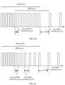
- FIG. 2A in a scenario in which only the ready timer is used, within a time period in which the ready timer does not expire, downlink scheduling data is monitored by using a second DRX (Discontinuous Reception, discontinuous reception) monitoring cycle, and within a time period after the ready timer expires, the downlink scheduling data is monitored by using a first DRX monitoring cycle. Further, an RDR timer may be used. As shown in FIG.
- the downlink scheduling data is monitored by using the second DRX monitoring cycle, and within a time period after the ready timer expires, the downlink scheduling data is monitored by using the first DRX monitoring cycle.
- the RDR timer needs to stop even though the RDR timer does not expire.
- FIG. 2B a case in which the ready timer expires, but the RDR timer does not expire is described. Certainly, when the ready timer expires, the RDR timer may have expired. As shown in FIG.
- the downlink scheduling data is monitored by using the second DRX monitoring cycle; within a time period in which the ready timer does not expire, but the RDR timer expires, the downlink scheduling data is monitored by using a third DRX monitoring cycle; and within a time period after the ready timer expires, the downlink scheduling data is monitored by using the first DRX monitoring cycle.
- the first DRX monitoring cycle is in a unit of minute or hour, and both the second DRX monitoring cycle and the third DRX monitoring cycle are in a unit of millisecond or second.
- the second DRX monitoring cycle may be the same as or different from the third DRX monitoring cycle.
- the present invention may be applied to an S1 architecture, and only an RDR timer may be used in the S1 architecture.
- RDR timer within a time period in which the RDR timer does not expire, downlink scheduling data is monitored by using a second DRX monitoring cycle, and within a time period after the RDR timer expires, the downlink scheduling data is monitored by using a first DRX monitoring cycle.
- a ready timer is a timer that is maintained by both a terminal and a core network.
- the core network herein may refer to an SGSN (Serving GPRS Support Node, serving support node, GPRS (General Packet Radio service, general packet radio service)).
- the terminal starts the ready timer after sending a last uplink LLC data packet, and the core network starts the ready timer after receiving the last uplink LLC data packet.
- An RDR timer is a timer that is set by both a terminal and a base station. On a terminal side, the terminal starts the RDR timer after sending a last uplink MAC layer data packet and receiving positive feedback information for the MAC layer data packet from the base station.
- the terminal After a ready timer on the terminal side expires, if the RDR timer does not expire, the terminal stops the RDR timer, and releases a connection on the terminal side.
- the base station starts the RDR timer after receiving the last uplink MAC layer data packet sent by the terminal and sending the positive feedback information for the MAC layer data packet to the terminal.
- the Gb architecture after a base station receives a paging message delivered by a core network, if an RDR timer does not expire, the RDR timer stops, and a connection to a terminal is released. If the timer expires, the base station releases a connection to the terminal.
- the S1 architecture after an RDR timer expires, a base station initiates a connection release request to a core network, and the core network releases an S1 connection to the terminal, and the base station releases an air interface connection to the terminal.
- a procedure of monitoring downlink scheduling data is as follows:
- Duration of the first DRX monitoring cycle is in a unit of minute or hour.
- downlink scheduling data is monitored by using a DRX monitoring cycle whose duration is in a unit of second or millisecond, and consequently, power consumption is relatively large, and a relationship between power saving of a device and timely receiving of the downlink scheduling data cannot be balanced.
- the downlink scheduling data is monitored by using the first DRX monitoring cycle whose duration is in a unit of minute or hour, and in this way, not only power consumption is reduced, but also the downlink scheduling data can be monitored.
- the following several manners may be used: monitoring, by using the first DRX monitoring cycle according to a scheduling identifier in an idle state or a scheduling identifier in a connected state, the downlink scheduling data sent by the base station.
- the monitoring, by using a first DRX monitoring cycle, downlink scheduling data sent by a base station may include: monitoring, by using the first DRX monitoring cycle according to the scheduling identifier in an idle state, the downlink scheduling data sent by the base station.
- a terminal may return to a long sleep state in an idle state, or may be still in a long sleep state in a connected state.
- the monitoring, by using a first DRX monitoring cycle, downlink scheduling data sent by a base station may include: monitoring, by using the first DRX monitoring cycle according to the scheduling identifier in an idle state, the downlink scheduling data sent by the base station.
- the monitoring, by using a first DRX monitoring cycle, downlink scheduling data sent by a base station may include: monitoring, by using the first DRX monitoring cycle according to the scheduling identifier in a connected state, the downlink scheduling data sent by the base station.
- the method before the downlink scheduling data sent by the base station is monitored by using the first DRX monitoring cycle, the method further includes the following operation:
- the terminal may send the supported first DRX monitoring cycle to a core network device.
- the timer described in step 300 may include only a ready timer (Ready Timer).
- the ready timer is configured to determine that the terminal is switched from a ready state to a standby state. That is, before the ready timer expires, the terminal is in a ready state, and after the ready timer expires, the terminal is in a standby state.
- the starting a timer may include:
- an RDR timer (Timer) may be further included.
- the RDR timer is configured to determine that the terminal is switched from a connected state to a long sleep state. That is, when the RDR timer does not expire, the terminal is in a connected state, and after the RDR timer expires, the terminal is in a long sleep state.
- the long sleep state includes a long sleep state in an idle state or a long sleep state in a connected state.
- the starting a timer may include: starting the ready timer and the RDR timer, where a time of starting the ready timer is earlier than a time of starting the RDR timer.
- the determining that the timer expires may include: determining that the ready timer expires.
- the downlink scheduling data sent by the base station may be monitored by using the first DRX monitoring cycle provided that the ready timer expires. In this case, if the ready timer expires, but the RDR timer does not expire, the RDR timer needs to stop, and a connection is released.
- the timer includes only a ready timer, or includes both a ready timer and an RDR timer.
- the timer may include only an RDR timer.
- the starting a timer may include:
- the method further includes the following operations:
- the following manner may be used: monitoring, at the DRX monitoring moment, the downlink scheduling data sent by the base station.
- the method further includes the following operation: when it is determined that the timer does not expire, monitoring, by using a second DRX monitoring cycle, the downlink scheduling data sent by the base station.
- Duration of the second DRX monitoring cycle is in a unit of millisecond or second.
- the downlink scheduling data sent by the base station is monitored by using the first DRX monitoring cycle, and before the timer expires, the downlink scheduling data sent by the base station is monitored by using the second DRX monitoring cycle.
- the method further includes the following operation:
- the timer includes only a ready timer, or includes only an RDR timer, or includes both a ready timer and an RDR timer.
- the timer includes only a ready timer, or includes only an RDR timer, or includes both a ready timer and an RDR timer. The following separately gives description.
- the determining that the timer does not expire may include:
- the determining that the timer does not expire may include:
- the starting a timer may include:
- the RDR timer may expire, or may not expire.
- the monitoring by using a second DRX monitoring cycle, the downlink scheduling data sent by the base station may include: monitoring, by using the second DRX monitoring cycle according to a scheduling identifier in a connected state, the downlink scheduling data sent by the base station.
- the downlink scheduling data sent by the base station needs to be monitored by using a third DRX monitoring cycle according to a scheduling identifier in an idle state.
- Duration of the third DRX monitoring cycle is in a unit of millisecond or second.
- the second DRX monitoring cycle may be the same as or different from the third DRX monitoring cycle. This is not specifically limited herein.
- the method before the downlink scheduling data sent by the base station is monitored by using the third DRX monitoring cycle, the method further includes the following operation:
- the following manner may be used: starting the ready timer and/or the RDR timer, where the ready timer is configured to determine that the terminal is switched from a ready state to a standby state, and the RDR timer is configured to determine that the terminal is switched from a connected state to a long sleep state.
- the following manner may be used: starting the ready timer when a last uplink LLC (Logical Link Control, logical link control) data packet is sent.
- uplink LLC Logical Link Control, logical link control
- starting the RDR timer There are multiple manners of starting the RDR timer. Optionally, the following manner may be used: starting the RDR timer when positive feedback information for a last uplink MAC (Medium Access Control, Media Access Control) layer data packet is received.
- MAC Medium Access Control, Media Access Control
- the terminal When monitoring the downlink scheduling data, for example, after obtaining a P-RNTI (Paging Radio Network Temporary Identifier, paging radio network temporary identifier) by means of monitoring, the terminal reads a paging record on a paging resource indicated by the P-RNTI. If there is a paging record that includes the identifier of the terminal, it indicates that the terminal is paged. If there is no paging record that includes the identifier of the terminal, it indicates that the terminal is not paged.
- P-RNTI Paging Radio Network Temporary Identifier, paging radio network temporary identifier
- the downlink scheduling data is downlink data, or may be a paging message, and certainly, may be in another form. This is not specifically limited herein.
- the method before the downlink scheduling data sent by the base station is monitored by using the first DRX monitoring cycle, the method further includes the following operations:
- the scheduling identifier in a connected state is in many forms, and optionally, may be a TBF (Temporary Block Flow, temporary block flow), or may be a C-RNTI (Cell Radio Network Temporary Identifier, cell radio network temporary identifier).
- TBF Temporary Block Flow, temporary block flow
- C-RNTI Cell Radio Network Temporary Identifier, cell radio network temporary identifier
- the scheduling identifier in an idle state is also in many forms, and optionally, may be a UE-dedicated scheduling identifier in an idle state, for example, a TLLI (Temporary Logical Link Identifier, temporary logical link identifier), an S-TMSI (SAE Temporary Mobile Subscriber Identity, SAE temporary mobile subscriber identity, SAE (System Architecture Evolution, system architecture evolution)), a P-TMSI (PS Temporary Mobile Subscriber Identity, PS temporary mobile subscriber identity, PS (Packet Switched, packet switched)), an IMSI (International Mobile Subscriber Identification Number, international mobile subscriber identity), or an IMSI mod N, or may be a common scheduling identifier in an idle state, for example, a P-RNTI (Paging Radio Network Temporary Identifier, paging radio network temporary identifier).
- TLLI Temporary Logical Link Identifier, temporary logical link identifier
- S-TMSI SAE Temporary Mobile Subscriber Identity, SAE temporary mobile
- a procedure of sending downlink scheduling data is as follows:
- Duration of the first sending cycle is in a unit of minute or hour.
- the downlink scheduling data directly carries the first DRX monitoring cycle, it may be directly determined, according to the first DRX monitoring cycle, that the terminal monitors the downlink scheduling data by using the first DRX monitoring cycle. If the downlink scheduling data does not carry the first DRX monitoring cycle, a type of the downlink scheduling data may be determined. If the type of the downlink scheduling data is a paging message, it is determined that the terminal monitors the downlink scheduling data by using the first DRX monitoring cycle.
- the terminal monitors the downlink scheduling data by using the first DRX monitoring cycle.
- an RDR timer in an S1 architecture expires, when the terminal is in a long sleep state in a connected state, it may be determined, by adding the first DRX monitoring cycle to the downlink scheduling data, that the terminal monitors the downlink scheduling data by using the first DRX monitoring cycle; or it may be determined, by determining that the RDR expires, that the terminal monitors the downlink scheduling data by using the first DRX monitoring cycle.
- the method before the downlink scheduling data is sent to the terminal by using the first sending cycle, the method further includes the following operations:
- the following manner may be used to determine that the terminal monitors the downlink scheduling data by using the first discontinuous reception DRX monitoring cycle: when it is determined that the RDR timer expires, determining that the terminal monitors the downlink scheduling data by using the first DRX monitoring cycle.
- the method before the downlink scheduling data is sent to the terminal by using the first sending cycle, the method further includes the following operations:
- the method before the downlink scheduling data is sent to the terminal by using the first sending cycle, the method further includes:
- the foregoing manner of determining the DRX sending moment is applied to a case in which when an RDR timer expires in the S1 architecture, the terminal is still in a long sleep state in a connected state.
- the terminal monitors the downlink scheduling data by using the first DRX monitoring cycle.
- the terminal may monitor the downlink scheduling data by using a second DRX monitoring cycle.
- the base station needs to send the downlink scheduling data by using a second sending cycle corresponding to the second DRX monitoring cycle. Therefore, in this embodiment of the present invention, before it is determined that the terminal monitors the downlink scheduling data by using the first discontinuous reception DRX monitoring cycle, the method further includes the following operation: determining that the terminal monitors the downlink scheduling data by using a second DRX monitoring cycle, and sending the downlink scheduling data to the terminal by using a second sending cycle.
- Duration of the second sending cycle is in a unit of millisecond or second.
- the terminal may not monitor the downlink scheduling data by using the second DRX monitoring cycle. Further, when an RDR timer starts and does not expire, it is determined that the terminal monitors the downlink scheduling data by using the second DRX monitoring cycle. Therefore, in this embodiment of the present invention, before the downlink scheduling data is sent to the terminal by using the second sending cycle, the method further includes the following operations:
- the method before the downlink scheduling data is sent to the terminal by using the second sending cycle, the method further includes the following operations:
- the terminal monitors the downlink scheduling data by using a third DRX monitoring cycle. Therefore, in this embodiment of the present invention, before the downlink scheduling data is sent to the terminal by using the first sending cycle, the method further includes the following operation: when it is determined that the terminal monitors the downlink scheduling data by using a third DRX monitoring cycle, sending the downlink scheduling data to the terminal by using a third sending cycle.
- Duration of the third sending cycle is from a millisecond range to a second range.
- the method before it is determined that the terminal monitors the downlink scheduling data by using the third DRX monitoring cycle, the method further includes the following operations:
- the method before it is determined that the terminal monitors the downlink scheduling data by using the third DRX monitoring cycle, the method further includes the following operations:
- the third sending cycle may be the same as or different from the second sending cycle. This is not specifically limited herein.
- the first DRX monitoring cycle, the second DRX monitoring cycle, and the third DRX monitoring cycle that are sent by the base station to the terminal may be determined by the base station, or may be sent by a core network.
- the base station may be determined by the base station, or may be sent by a core network.
- another manner may be used, and this is not specifically limited herein.
- the terminal includes a starting unit 50, a determining unit 51, and a monitoring unit 52.
- the starting unit 50 is configured to start a timer.
- the determining unit 51 is configured to determine that the timer expires.
- the monitoring unit 52 is configured to: after the determining unit 51 determines that the timer expires, monitor, by using a first discontinuous reception DRX monitoring cycle, downlink scheduling data sent by a base station.
- Duration of the first DRX monitoring cycle is in a unit of minute or hour.
- the monitoring unit 52 is configured to: monitor, by using the first DRX monitoring cycle according to a scheduling identifier in an idle state or a scheduling identifier in a connected state, the downlink scheduling data sent by the base station.
- the terminal further includes a receiving unit 53.
- the receiving unit 53 is configured to receive a first DRX monitoring cycle that is sent by the base station in a broadcast manner or a dedicated signaling manner and that is supported by the base station, and the determining unit 51 is further configured to use the first DRX monitoring cycle supported by the base station as the first DRX monitoring cycle; or
- the timer includes a ready timer (Ready Timer), and the ready timer is configured to determine that the terminal is switched from a ready state to a standby state.
- Ready Timer Ready Timer
- the timer further includes a reduced downlink control signal reception RDR timer (RDR Timer), and the RDR timer is configured to determine that the terminal is switched from a connected state to a long sleep state.
- RDR Timer reduced downlink control signal reception RDR timer
- the starting unit 50 is configured to start the ready timer and the RDR timer, where a time of starting the ready timer is earlier than a time of starting the RDR timer.
- the determining unit 51 is configured to determine that the ready timer expires.
- the timer includes an RDR timer (RDR Timer), and the RDR timer is configured to determine that the terminal is switched from a connected state to a long sleep state.
- RDR Timer RDR Timer
- the determining unit 51 is further configured to: determine an initial monitoring moment; and determine a DRX monitoring moment according to the initial monitoring moment, where the DRX monitoring moment is a moment at a distance of N first DRX monitoring cycles from the initial monitoring moment, and N is a positive integer greater than or equal to 0.
- the monitoring unit 52 is configured to monitor, at the DRX monitoring moment, the downlink scheduling data sent by the base station.
- determining unit 51 determines an initial monitoring moment is specifically:
- the determining unit 51 is further configured to determine that the timer does not expire.
- the monitoring unit 52 is further configured to: when the determining unit 51 determines that the timer does not expire, monitor, by using a second DRX monitoring cycle, the downlink scheduling data sent by the base station.
- Duration of the second DRX monitoring cycle is in a unit of millisecond or second.
- the terminal further includes a receiving unit 53.
- the receiving unit 53 is configured to receive a second DRX monitoring cycle that is sent by the base station in a broadcast manner or a dedicated signaling manner and that is supported by the base station, and the determining unit 51 is further configured to use the second DRX monitoring cycle supported by the base station as the second DRX monitoring cycle; or
- the timer includes a ready timer, and the ready timer is configured to determine that the terminal is switched from a ready state to a standby state.
- the monitoring unit 52 is configured to monitor, by using the second DRX monitoring cycle according to a scheduling identifier in an idle state, the downlink scheduling data sent by the base station.
- the timer includes an RDR timer, and the RDR timer is configured to determine that the terminal is switched from a connected state to a long sleep state.
- the monitoring unit 52 is configured to monitor, by using the second DRX monitoring cycle according to a scheduling identifier in a connected state, the downlink scheduling data sent by the base station.
- the timer includes a ready timer and an RDR timer
- the ready timer is configured to determine that the terminal is switched from a ready state to a standby state
- the RDR timer is configured to determine that the terminal is switched from a connected state to a long sleep state.
- the starting unit 50 is configured to start the ready timer and the RDR timer, where a time of starting the ready timer is earlier than a time of starting the RDR timer.
- That the determining unit 51 determines that the timer does not expire is specifically: determining that the ready timer does not expire.
- the determining unit 51 is further configured to determine that the RDR timer does not expire.
- the monitoring unit 52 is configured to monitor, by using the second DRX monitoring cycle according to a scheduling identifier in a connected state, the downlink scheduling data sent by the base station.
- the determining unit 51 is further configured to determine that the RDR timer expires.
- the monitoring unit 52 is further configured to monitor, by using a third DRX monitoring cycle according to a scheduling identifier in an idle state, the downlink scheduling data sent by the base station.
- Duration of the third DRX monitoring cycle is in a unit of millisecond or second.
- the terminal further includes a receiving unit 53.
- the receiving unit 53 is configured to receive a third DRX monitoring cycle that is sent by the base station in a broadcast manner or a dedicated signaling manner and that is supported by the base station, and the determining unit 51 is further configured to use the third DRX monitoring cycle supported by the base station as the third DRX monitoring cycle; or
- the starting unit 50 is configured to start the ready timer and/or the RDR timer, the ready timer is configured to determine that the terminal is switched from a ready state to a standby state, and the RDR timer is configured to determine that the terminal is switched from a connected state to a long sleep state.
- the starting unit 50 starts the ready timer is specifically:
- the terminal includes a processor 500 and a receiver 510.
- the processor 500 is configured to start a timer.
- the processor 500 is further configured to determine that the timer expires.
- the receiver 510 is configured to: after the processor 500 determines that the timer expires, monitor, by using a first discontinuous reception DRX monitoring cycle, downlink scheduling data sent by a base station.
- Duration of the first DRX monitoring cycle is in a unit of minute or hour.
- the processor 500 may further perform other operations performed by the starting unit 50 and the determining unit 51 that are shown in FIG. 5A
- the receiver 510 may further perform other operations performed by the monitoring unit 52 and the receiving unit 53 that are shown in FIG. 5A .
- the base station includes a receiving unit 60, a determining unit 61, and a sending unit 62.
- the receiving unit 60 is configured to receive downlink scheduling data sent by a core network device to a terminal.
- the determining unit 61 is configured to determine that the terminal monitors the downlink scheduling data by using a first discontinuous reception DRX monitoring cycle.
- the sending unit 62 is configured to: when the determining unit 61 determines that the terminal monitors the downlink scheduling data by using the first discontinuous reception DRX monitoring cycle, send the downlink scheduling data to the terminal by using a first sending cycle.
- Duration of the first sending cycle is in a unit of minute or hour.
- the determining unit 61 is configured to: determine, according to the first DRX monitoring cycle carried in the downlink scheduling data, that the terminal monitors the downlink scheduling data by using the first DRX monitoring cycle; or when determining that the downlink scheduling data is a paging message, determine that the terminal monitors the downlink scheduling data by using the first DRX monitoring cycle.
- the receiving unit 60 is further configured to receive a last uplink Media Access Control MAC layer data packet sent by the terminal.
- the sending unit 62 is further configured to send positive feedback information for the last uplink MAC layer data packet to the terminal.
- the base station further includes a starting unit 63, configured to start a reduced downlink control signal reception RDR timer when the sending unit 62 sends the positive feedback information for the last uplink MAC layer data packet to the terminal, where the RDR timer is configured to determine that the terminal is switched from a connected state to a long sleep state.
- a starting unit 63 configured to start a reduced downlink control signal reception RDR timer when the sending unit 62 sends the positive feedback information for the last uplink MAC layer data packet to the terminal, where the RDR timer is configured to determine that the terminal is switched from a connected state to a long sleep state.
- the determining unit 61 is configured to: when determining that the RDR timer expires, determine that the terminal monitors the downlink scheduling data by using the first DRX monitoring cycle.
- the sending unit 62 is further configured to: send the first DRX monitoring cycle to the terminal in a broadcast manner or a dedicated signaling manner; or send, in a broadcast manner or a dedicated signaling manner, a first DRX monitoring cycle supported by the base station to the terminal; and/or send, in a form of uplink data at a logical link control layer, the first DRX monitoring cycle supported by the base station to the core network device.
- the determining unit 61 is further configured to: determine an initial sending moment; and determine a DRX sending moment according to the initial sending moment, where the DRX sending moment is a moment at a distance of N first sending cycles from the initial sending moment, and N is a positive integer greater than or equal to 0.
- the sending unit 62 is configured to send the downlink scheduling data at the DRX sending moment.
- determining unit 61 determines an initial sending moment is specifically:
- the determining unit 61 is further configured to determine that the terminal monitors the downlink scheduling data by using a second DRX monitoring cycle.
- the sending unit 62 is further configured to send the downlink scheduling data to the terminal by using a second sending cycle.
- Duration of the second sending cycle is in a unit of millisecond or second.
- the determining unit 61 determines that the terminal monitors the downlink scheduling data by using a second DRX monitoring cycle is specifically:
- the receiving unit 60 is further configured to receive a last uplink Media Access Control MAC layer data packet sent by the terminal.
- the sending unit 62 is further configured to send positive feedback information for the last uplink MAC layer data packet to the terminal.
- the base station further includes a starting unit 63, configured to start an RDR timer when the sending unit 62 sends the positive feedback information for the last uplink MAC layer data packet to the terminal, where the RDR timer is configured to determine that the terminal is switched from a connected state to a long sleep state.
- That the determining unit 61 determines that the terminal monitors the downlink scheduling data by using a second DRX monitoring cycle is specifically: when determining that the downlink scheduling data is downlink data, and the RDR timer does not expire, determining that the terminal monitors the downlink scheduling data by using the second DRX monitoring cycle.
- the sending unit 62 is further configured to: send the second DRX monitoring cycle to the terminal in a broadcast manner or a dedicated signaling manner; or send, in a broadcast manner or a dedicated signaling manner, a second DRX monitoring cycle supported by the base station to the terminal; and/or send, in a form of uplink data at a logical link control layer, the second DRX monitoring cycle supported by the base station to the core network device.
- the determining unit 61 is further configured to determine that the terminal monitors the downlink scheduling data by using a third DRX monitoring cycle.
- the sending unit 62 is further configured to: when the determining unit 61 determines that the terminal monitors the downlink scheduling data by using the third DRX monitoring cycle, send the downlink scheduling data to the terminal by using a third sending cycle.
- Duration of the third sending cycle is from a millisecond range to a second range.
- the receiving unit 60 is further configured to receive a last uplink Media Access Control MAC layer data packet sent by the terminal.
- the sending unit 62 is further configured to send positive feedback information for the last uplink MAC layer data packet to the terminal.
- the base station further includes a starting unit 63, configured to start an RDR timer when the sending unit 62 sends the positive feedback information for the last uplink MAC layer data packet to the terminal, where the RDR timer is configured to determine that the terminal is switched from a connected state to a long sleep state.
- That the determining unit 61 determines that the terminal monitors the downlink scheduling data by using a third DRX monitoring cycle is specifically: when determining that the downlink scheduling data is downlink data, and the RDR timer expires, determining that the terminal monitors the downlink scheduling data by using the third DRX monitoring cycle.
- the sending unit 62 is further configured to: send the third DRX monitoring cycle to the terminal in a broadcast manner or a dedicated signaling manner; and/or send the third DRX monitoring cycle to the core network device in a form of uplink data at a logical link control layer.
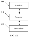
- the terminal includes a receiver 600, a processor 610, and a transmitter 620.
- the receiver 600 is configured to receive downlink scheduling data sent by a core network device to the terminal.
- the processor 610 is configured to determine that the terminal monitors the downlink scheduling data by using a first discontinuous reception DRX monitoring cycle.
- the transmitter 620 is configured to: when the processor 610 determines that the terminal monitors the downlink scheduling data by using the first discontinuous reception DRX monitoring cycle, send the downlink scheduling data to the terminal by using a first sending cycle.
- Duration of the first sending cycle is in a unit of minute or hour.
- the receiver 600 may further perform other operations performed by the receiving unit 60 shown in FIG. 6A
- the processor 610 may further perform other operations performed by the determining unit 61 and the starting unit 63 that are shown in FIG. 6A
- the transmitter 620 may further perform other operations performed by the sending unit 62 shown in FIG. 6A .
- These computer program instructions may be provided for a general-purpose computer, a dedicated computer, an embedded processor, or a processor of any other programmable data processing device to generate a machine, so that the instructions executed by a computer or a processor of any other programmable data processing device generate an apparatus for implementing a specific function in one or more processes in the flowcharts and/or in one or more blocks in the block diagrams.
- These computer program instructions may also be stored in a computer readable memory that can instruct the computer or any other programmable data processing device to work in a specific manner, so that the instructions stored in the computer readable memory generate an artifact that includes an instruction apparatus.
- the instruction apparatus implements a specific function in one or more processes in the flowcharts and/or in one or more blocks in the block diagrams.
- These computer program instructions may also be loaded onto a computer or another programmable data processing device, so that a series of operations and steps are performed on the computer or the another programmable device, thereby generating computer-implemented processing. Therefore, the instructions executed on the computer or the another programmable device provide steps for implementing a specific function in one or more processes in the flowcharts and/or in one or more blocks in the block diagrams.
Landscapes
- Engineering & Computer Science (AREA)
- Computer Networks & Wireless Communication (AREA)
- Signal Processing (AREA)
- Mobile Radio Communication Systems (AREA)
- Transceivers (AREA)
- Circuits Of Receivers In General (AREA)
Claims (9)
- Verfahren zum Senden von Downlink-Planungsdaten, umfassend:Empfangen (400), durch eine Basisstation, von Downlink-Planungsdaten, die von einer Kernnetzwerkvorrichtung an ein Endgerät gesendet werden; undwenn von der Basisstation festgestellt wird, dass es sich bei den Downlink-Planungsdaten um eine Paging-Nachricht handelt,Bestimmen, durch die Basisstation, dass das Endgerät die Paging-Nachricht überwacht, indem es einen ersten Überwachungszyklus für diskontinuierlichen Empfang (DRX) gemäß einer Planungskennung im Leerlaufzustand verwendet,Senden (410) der Paging-Nachricht durch die Basisstation an das Endgerät unter Verwendung eines ersten Sendezyklus, wobei die Dauer des ersten Sendezyklus in einer Einheit von Minuten oder Stunden angegeben wird,wenn von der Basisstation festgestellt wird, dass die Downlink-Planungsdaten Downlink-Daten sind,Bestimmen, durch die Basisstation, dass das Endgerät die Downlink-Daten überwacht, indem es einen zweiten DRX-Überwachungszyklus gemäß einer Planungskennung im verbundenen Zustand verwendet, und Senden der Downlink-Daten durch die Basisstation an das Endgerät unter Verwendung eines zweiten Sendezyklus, wobeieine Dauer des zweiten Sendezyklus kürzer als die Dauer des ersten Sendezyklus ist und die Einheit Millisekunde oder Sekunde ist;wobei das Verfahren vor dem Senden der Downlink-Daten an das Endgerät unter Verwendung des zweiten Sendezyklus ferner Folgendes umfasst:
Senden des zweiten DRX-Überwachungszyklus durch die Basisstation an das Endgerät in einer dedizierten Signalisierungsmethode. - Verfahren nach Anspruch 1, wobei das Verfahren vor dem Senden der Paging-Nachricht an das Endgerät unter Verwendung des ersten Sendezyklus ferner Folgendes umfasst:Senden des ersten DRX-Überwachungszyklus an das Endgerät in Form einer Broadcast-Meldung oder einer dedizierten Signalisierungsmethode; oder Senden des ersten von einer Basisstation unterstützten DRX-Überwachungszyklus an das Endgerät in Form einer Broadcast-Meldung oder einer dedizierten Signalisierungsmethode; und/oderSenden des ersten von der Basisstation unterstützten DRX-Überwachungszyklus in Form von Uplink-Daten auf einer logischen Verbindungssteuerungsebene an die Kernnetzwerkvorrichtung.
- Verfahren nach Anspruch 1, wobei das Bestimmen, dass das Endgerät die Downlink-Daten unter Verwendung des zweiten DRX-Überwachungszyklus überwacht, Folgendes umfasst:
Bestimmen, gemäß dem in den Downlink-Daten enthaltenen zweiten DRX-Überwachungszyklus, dass das Endgerät die Downlink-Daten unter Verwendung des zweiten DRX-Überwachungszyklus überwacht. - Basisstation, Folgendes umfassend:eine Empfangseinheit (60), die zum Empfangen von Downlink-Planungsdaten konfiguriert ist, die von einer Kernnetzwerkvorrichtung an ein Endgerät gesendet werden;eine Bestimmungseinheit (61), die dazu konfiguriert ist, zu bestimmen, dass das Endgerät die Downlink-Planungsdaten unter Verwendung eines Überwachungszyklus für diskontinuierlichen Empfang (DRX) überwacht; undeine Sendeeinheit (62), die zu Folgendem konfiguriert ist:wenn von der Bestimmungseinheit (61) bestimmt wird, dass die Downlink-Planungsdaten eine Paging-Nachricht sind, und wenn die Bestimmungseinheit (61) bestimmt, dass das Endgerät die Paging-Nachricht unter Verwendung eines ersten DRX-Überwachungszyklus gemäß einer Planungskennung im Leerlaufzustand überwacht, Senden der Paging-Nachrichtendaten an das Endgerät unter Verwendung eines ersten Sendezyklus, wobei eine Dauer des ersten Sendezyklus in einer Einheit von Minuten oder Stunden angegeben wird,wenn durch die Bestimmungseinheit (61) bestimmt wird, dass die Downlink-Planungsdaten Downlink-Daten sind, und wenn die Bestimmungseinheit (61) bestimmt, dass das Endgerät die Downlink-Daten unter Verwendung eines zweiten DRX-Überwachungszyklus gemäß der Planungskennung im verbundenen Zustand überwacht, Senden der Downlink-Daten an das Endgerät unter Verwendung eines zweiten Sendezyklus, wobei eine Dauer des zweiten Sendezyklus kürzer als die Dauer des ersten Sendezyklus ist und in einer Einheit von Millisekunden oder Sekunden angegeben wird;wobei die Sendeeinheit (62) ferner dazu konfiguriert ist, den zweiten DRX-Überwachungszyklus in einer dedizierten Signalisierungsart an das Endgerät zu senden, bevor die Sendeeinheit (62) die Downlink-Daten unter Verwendung des zweiten Sendezyklus an das Endgerät sendet.
- Die Basisstation nach Anspruch 4, wobei die Empfangseinheit ferner dazu konfiguriert ist, ein letztes vom Endgerät gesendetes Datenpaket der Uplink-Media Access Control-Schicht (MAC) zu empfangen;die Sendeeinheit ist ferner dazu konfiguriert, positive Feedback-Informationen für das letzte Uplink-MAC-Schicht-Datenpaket an das Endgerät zu senden;die Basisstation ferner eine Starteinheit umfasst, die dazu konfiguriert ist, einen RDR-Zeitgeber für den reduzierten Downlink-Steuersignalempfang zu starten, wenn die Sendeeinheit die positiven Feedback-Informationen für das letzte Uplink-MAC-Schicht-Datenpaket an das Endgerät sendet, wobei der RDR-Zeitgeber dazu konfiguriert ist, zu bestimmen, dass das Endgerät von einem verbundenen Zustand in einen langen Ruhezustand geschaltet wird; unddie Bestimmungseinheit zu Folgendem konfiguriert: bei dem Bestimmen, dass der RDR-Zeitgeber abgelaufen ist, bestimmen, dass das Endgerät die Downlink-Planungsdaten unter Verwendung des ersten DRX-Überwachungszyklus überwacht.
- Basisstation nach einem der Ansprüche 4 bis 5, wobei die Sendeeinheit ferner für Folgendes konfiguriert ist: den ersten DRX-Überwachungszyklus in einer Broadcast-Weise oder einer dedizierten Signalisierungs-Weise an das Endgerät zu senden; oder den ersten von der Basisstation unterstützten DRX-Überwachungszyklus in einer Broadcast-Weise oder einer dedizierten Signalisierungs-Weise an das Endgerät zu senden; und/oder
Senden des ersten von der Basisstation unterstützten DRX-Überwachungszyklus in Form von Uplink-Daten auf einer logischen Verbindungssteuerungsebene an die Kernnetzwerkvorrichtung. - Basisstation nach Anspruch 4, wobei die Bestimmungseinheit bestimmt, dass das Endgerät die Downlink-Planungsdaten unter Verwendung des zweiten DRX-Überwachungszyklus überwacht, und zwar insbesondere:Bestimmen, gemäß dem in den Downlink-Planungsdaten enthaltenen zweiten DRX-Überwachungszyklus, dass das Endgerät die Downlink-Planungsdaten unter Verwendung des zweiten DRX-Überwachungszyklus überwacht; oderbeim Bestimmen, dass es sich bei den Downlink-Planungsdaten um Downlink-Daten handelt, Bestimmen, dass das Endgerät die Downlink-Planungsdaten unter Verwendung des zweiten DRX-Überwachungszyklus überwacht.
- Computerlesbares Speichermedium, umfassend Anweisungen, die bei Ausführung durch einen Computer den Computer dazu veranlassen, das Verfahren nach einem der Ansprüche 1 bis 3 durchzuführen.
- Computerprogramm, umfassend Anweisungen, die, wenn durch einen Computer ausgeführt, den Computer dazu veranlassen, das Verfahren nach einem der Ansprüche 1 bis 3 durchzuführen.
Priority Applications (1)
| Application Number | Priority Date | Filing Date | Title |
|---|---|---|---|
| EP25173530.4A EP4615115A3 (de) | 2015-05-19 | 2016-03-07 | Verfahren zur überwachung von downlink-planungsdaten, verfahren zum senden von downlink-planungsdaten und vorrichtung |
Applications Claiming Priority (2)
| Application Number | Priority Date | Filing Date | Title |
|---|---|---|---|
| CN201510257300.2A CN106304129B (zh) | 2015-05-19 | 2015-05-19 | 一种监听及发送下行调度数据的方法及装置 |
| PCT/CN2016/075805 WO2016184224A1 (zh) | 2015-05-19 | 2016-03-07 | 一种监听及发送下行调度数据的方法及装置 |
Related Child Applications (1)
| Application Number | Title | Priority Date | Filing Date |
|---|---|---|---|
| EP25173530.4A Division EP4615115A3 (de) | 2015-05-19 | 2016-03-07 | Verfahren zur überwachung von downlink-planungsdaten, verfahren zum senden von downlink-planungsdaten und vorrichtung |
Publications (3)
| Publication Number | Publication Date |
|---|---|
| EP3288317A1 EP3288317A1 (de) | 2018-02-28 |
| EP3288317A4 EP3288317A4 (de) | 2018-08-29 |
| EP3288317B1 true EP3288317B1 (de) | 2025-05-21 |
Family
ID=57319287
Family Applications (2)
| Application Number | Title | Priority Date | Filing Date |
|---|---|---|---|
| EP25173530.4A Pending EP4615115A3 (de) | 2015-05-19 | 2016-03-07 | Verfahren zur überwachung von downlink-planungsdaten, verfahren zum senden von downlink-planungsdaten und vorrichtung |
| EP16795711.7A Active EP3288317B1 (de) | 2015-05-19 | 2016-03-07 | Verfahren und vorrichtung zur überwachung und übertragung von downlink-planungsdaten |
Family Applications Before (1)
| Application Number | Title | Priority Date | Filing Date |
|---|---|---|---|
| EP25173530.4A Pending EP4615115A3 (de) | 2015-05-19 | 2016-03-07 | Verfahren zur überwachung von downlink-planungsdaten, verfahren zum senden von downlink-planungsdaten und vorrichtung |
Country Status (6)
| Country | Link |
|---|---|
| US (3) | US10694462B2 (de) |
| EP (2) | EP4615115A3 (de) |
| JP (2) | JP6510076B2 (de) |
| CN (2) | CN106304129B (de) |
| MX (1) | MX381656B (de) |
| WO (1) | WO2016184224A1 (de) |
Families Citing this family (10)
| Publication number | Priority date | Publication date | Assignee | Title |
|---|---|---|---|---|
| CN106304129B (zh) * | 2015-05-19 | 2020-02-14 | 华为技术有限公司 | 一种监听及发送下行调度数据的方法及装置 |
| CN109246801B (zh) * | 2017-05-04 | 2022-01-25 | 成都鼎桥通信技术有限公司 | 空闲监听态终端实现非连续接收的方法及装置 |
| CN109246625B (zh) * | 2017-06-07 | 2022-04-26 | 成都鼎桥通信技术有限公司 | 集群非连续接收调度方法和系统 |
| WO2019028760A1 (zh) * | 2017-08-10 | 2019-02-14 | 富士通株式会社 | 资源指示和接收方法、装置及通信系统 |
| CN109982416B (zh) * | 2017-12-27 | 2022-04-12 | 珠海市魅族科技有限公司 | 一种数据接收及发送的方法及装置 |
| US12343563B2 (en) * | 2018-05-07 | 2025-07-01 | Dalhousie University | Systems and methods for planning, controlling and/or delivering radiotherapy and radiosurgery using combined optimization of dynamic axes (CODA) |
| EP3837915A1 (de) | 2018-09-28 | 2021-06-23 | Sony Corporation | Verfahren, kommunikationsvorrichtung und infrastrukturausrüstung |
| CN111132276B (zh) * | 2018-10-31 | 2021-10-01 | 华为技术有限公司 | 无线通信方法及终端设备 |
| US11690123B2 (en) * | 2020-02-12 | 2023-06-27 | Qualcomm Incorporated | Data inactivity indication and expedited recovery action |
| CN113905406B (zh) * | 2020-06-22 | 2024-10-22 | 大唐移动通信设备有限公司 | 一种信号传输方法及设备 |
Family Cites Families (31)
| Publication number | Priority date | Publication date | Assignee | Title |
|---|---|---|---|---|
| WO2007148930A1 (en) * | 2006-06-21 | 2007-12-27 | Electronics And Telecommunications Research Institute | Method to transmit downlink signaling message on cellular systems for packet transmission and method for receiving the message |
| KR20080097338A (ko) * | 2007-05-01 | 2008-11-05 | 엘지전자 주식회사 | 불연속 데이터 송수신 방법 |
| CN102067683B (zh) * | 2008-04-25 | 2014-12-10 | 黑莓有限公司 | 用于无线网络中不连续接收的控制的方法和系统 |
| US8311593B2 (en) * | 2008-08-11 | 2012-11-13 | Motorola Mobility Llc | Method and apparatus for adjusting an on duration in a discontinuous receive transmission mode |
| EP2369890A1 (de) | 2010-03-26 | 2011-09-28 | Panasonic Corporation | Verbindungsspitzenvermeidung für MTC-Vorrichtungen |
| US8688119B2 (en) * | 2010-04-30 | 2014-04-01 | Telefonaktiebolaget Lm Ericsson (Publ) | Method, apparatus and system for mobility enhancement in DRX |
| JP5720215B2 (ja) * | 2010-12-06 | 2015-05-20 | ソニー株式会社 | ゲートウェイ装置および通信方法 |
| US8879667B2 (en) * | 2011-07-01 | 2014-11-04 | Intel Corporation | Layer shifting in open loop multiple-input, multiple-output communications |
| CN103748833B (zh) * | 2011-08-01 | 2017-10-03 | 英特尔公司 | 对于网络接入控制的方法和系统 |
| US9042286B2 (en) | 2011-11-04 | 2015-05-26 | Intel Corporation | Reducing wireless power consumption and signaling overhead for internet application background messages |
| EP3125617B1 (de) * | 2011-12-02 | 2019-07-03 | Sony Corporation | Kommunikationsendgerät, kommunikationsverfahren, basisstation und kommunikationssystem |
| US20130223307A1 (en) * | 2012-02-24 | 2013-08-29 | Telefonaktiebolaget Lm Ericsson (Publ) | Combating drx deadlock in telecommunications |
| WO2013164025A1 (en) * | 2012-05-03 | 2013-11-07 | Telefonaktiebolaget L M Ericsson (Publ) | Telecommunication systems with discontinuous reception |
| CN110602669B (zh) * | 2012-05-09 | 2023-08-18 | 交互数字专利控股公司 | 处理mtc长drx周期/睡眠长度 |
| US9374845B2 (en) * | 2012-05-18 | 2016-06-21 | Qualcomm Incorporated | Method and apparatus for joint HARQ and DRX optimization for low cost MTC devices |
| WO2014070077A1 (en) * | 2012-10-29 | 2014-05-08 | Telefonaktiebolaget L M Ericsson (Publ) | Wake-up for measurements during drx cycles |
| US9420511B2 (en) * | 2012-11-01 | 2016-08-16 | Intel Corporation | Signaling QoS requirements and UE power preference in LTE-A networks |
| GB2508241A (en) * | 2012-11-27 | 2014-05-28 | Nec Corp | Scheduled Discontinuous Reception in a Mobile Device |
| PL2929751T3 (pl) * | 2012-12-10 | 2017-04-28 | Telefonaktiebolaget Lm Ericsson (Publ) | Urządzenie bezprzewodowe, węzeł sieci radiowej i sposoby nieciągłego odbioru w łączności bezpośredniej pomiędzy urządzeniami |
| US20160057738A1 (en) * | 2013-05-09 | 2016-02-25 | Lg Electronics Inc. | Method for monitoring paging occasions in a wireless communication system and device therefor |
| US9398634B2 (en) * | 2013-08-22 | 2016-07-19 | Telefonaktiebolaget Lm Ericsson (Publ) | Mobile station, core network node, base station subsystem, and methods for implementing longer paging cycles in a cellular network |
| WO2015065041A1 (en) * | 2013-11-01 | 2015-05-07 | Lg Electronics Inc. | Method and apparatus for transmitting paging message in wireless communication system |
| CN103889039B (zh) * | 2014-04-18 | 2017-05-10 | 大唐移动通信设备有限公司 | 基于非连续接收功能的省电方法及设备 |
| US10051570B2 (en) * | 2014-11-06 | 2018-08-14 | Sierra Wireless, Inc. | Method and apparatus for communication of system information in a wireless system |
| EP3235334B1 (de) * | 2014-12-17 | 2019-02-20 | Telefonaktiebolaget LM Ericsson (publ) | Handhabung von unterbrechungen während drx-einschaltdauern |
| WO2016140272A1 (ja) * | 2015-03-03 | 2016-09-09 | 京セラ株式会社 | 無線端末及び基地局 |
| US9883482B2 (en) * | 2015-03-05 | 2018-01-30 | Telefonaktiebolaget Lm Ericsson (Publ) | Signaling of core network restart to wireless devices |
| EP3627961B1 (de) * | 2015-03-25 | 2021-05-26 | LG Electronics Inc. | Verfahren zur überwachung der erreichbarkeit einer benutzervorrichtung in einem drahtloskommunikationssystem und vorrichtung dafür |
| EP3281490B1 (de) * | 2015-04-10 | 2019-10-23 | INTEL Corporation | Drx in einem gerät mit bereit status |
| US10172183B2 (en) * | 2015-05-19 | 2019-01-01 | Telefonaktiebolaget Lm Ericsson (Publ) | Radio access network node and method—time coordinated cells for extended discontinuous receive (eDRX) |
| CN106304129B (zh) * | 2015-05-19 | 2020-02-14 | 华为技术有限公司 | 一种监听及发送下行调度数据的方法及装置 |
-
2015
- 2015-05-19 CN CN201510257300.2A patent/CN106304129B/zh active Active
- 2015-05-19 CN CN202010071996.0A patent/CN111263336A/zh active Pending
-
2016
- 2016-03-07 MX MX2017014836A patent/MX381656B/es unknown
- 2016-03-07 WO PCT/CN2016/075805 patent/WO2016184224A1/zh not_active Ceased
- 2016-03-07 EP EP25173530.4A patent/EP4615115A3/de active Pending
- 2016-03-07 EP EP16795711.7A patent/EP3288317B1/de active Active
- 2016-03-07 JP JP2017560225A patent/JP6510076B2/ja active Active
-
2017
- 2017-11-19 US US15/817,266 patent/US10694462B2/en active Active
-
2019
- 2019-04-03 JP JP2019071505A patent/JP7150657B2/ja active Active
-
2020
- 2020-05-28 US US16/885,306 patent/US11350362B2/en active Active
-
2022
- 2022-05-05 US US17/737,671 patent/US11785542B2/en active Active
Also Published As
| Publication number | Publication date |
|---|---|
| WO2016184224A1 (zh) | 2016-11-24 |
| US20200367162A1 (en) | 2020-11-19 |
| MX2017014836A (es) | 2018-03-14 |
| JP2018516012A (ja) | 2018-06-14 |
| EP4615115A3 (de) | 2025-12-10 |
| MX381656B (es) | 2025-03-13 |
| EP3288317A4 (de) | 2018-08-29 |
| US20220264457A1 (en) | 2022-08-18 |
| JP6510076B2 (ja) | 2019-05-08 |
| US11785542B2 (en) | 2023-10-10 |
| CN106304129A (zh) | 2017-01-04 |
| JP7150657B2 (ja) | 2022-10-11 |
| JP2019118147A (ja) | 2019-07-18 |
| US11350362B2 (en) | 2022-05-31 |
| US20180110005A1 (en) | 2018-04-19 |
| EP3288317A1 (de) | 2018-02-28 |
| CN111263336A (zh) | 2020-06-09 |
| US10694462B2 (en) | 2020-06-23 |
| EP4615115A2 (de) | 2025-09-10 |
| CN106304129B (zh) | 2020-02-14 |
Similar Documents
| Publication | Publication Date | Title |
|---|---|---|
| US11785542B2 (en) | Downlink scheduling data monitoring method, downlink scheduling data sending method, and apparatus | |
| US12256459B2 (en) | Pre-configured dedicated resource for idle mode transmissions | |
| EP3152963B1 (de) | Benutzergerät, mobilfunkkommunikationsnetzknoten und verfahren zur steuerung des betriebs eines benutzergeräts | |
| EP2575382A1 (de) | Verfahren zum Zuweisen von Ressourcen in einem drahtlosen Breitbandzugangssystem | |
| EP2632213B1 (de) | Verfahren und vorrichtung zur durchführung einer netzwerk-eingabe/-neueingabe in einem drahtlosen kommunikationssystem | |
| US9344859B2 (en) | Method of receiving multicast data in a wireless communication system, and device for same | |
| US10187871B2 (en) | Paging method and device for network and terminal | |
| US9125026B2 (en) | Method for receiving multicast data in wireless communication system and M2M device therefor | |
| JP6206600B2 (ja) | 移動体無線通信装置、ネットワーク装置及び方法 | |
| JP2014502075A (ja) | マルチキャストトラフィック送受信のためのm2m機器及び基地局、及びその実行方法 | |
| CN109246801B (zh) | 空闲监听态终端实现非连续接收的方法及装置 | |
| US10237825B2 (en) | Data processing apparatus and method | |
| US20230209645A1 (en) | Drx packet wake-up method and apparatus, communication device, and storage medium | |
| US10142930B2 (en) | Terminal, wireless network and communication methods with low power consumption | |
| CN112867106B (zh) | 通信方法、系统以及无线接入点 | |
| CN116671189B (zh) | 定时器状态更改方法、装置、终端及存储介质 | |
| WO2016165079A1 (zh) | 一种监听下行控制信息的方法、装置和系统 |
Legal Events
| Date | Code | Title | Description |
|---|---|---|---|
| STAA | Information on the status of an ep patent application or granted ep patent |
Free format text: STATUS: THE INTERNATIONAL PUBLICATION HAS BEEN MADE |
|
| PUAI | Public reference made under article 153(3) epc to a published international application that has entered the european phase |
Free format text: ORIGINAL CODE: 0009012 |
|
| STAA | Information on the status of an ep patent application or granted ep patent |
Free format text: STATUS: REQUEST FOR EXAMINATION WAS MADE |
|
| 17P | Request for examination filed |
Effective date: 20171122 |
|
| AK | Designated contracting states |
Kind code of ref document: A1 Designated state(s): AL AT BE BG CH CY CZ DE DK EE ES FI FR GB GR HR HU IE IS IT LI LT LU LV MC MK MT NL NO PL PT RO RS SE SI SK SM TR |
|
| AX | Request for extension of the european patent |
Extension state: BA ME |
|
| DAV | Request for validation of the european patent (deleted) | ||
| DAX | Request for extension of the european patent (deleted) | ||
| A4 | Supplementary search report drawn up and despatched |
Effective date: 20180731 |
|
| RIC1 | Information provided on ipc code assigned before grant |
Ipc: H04W 76/28 20180101ALI20180725BHEP Ipc: H04W 52/02 20090101AFI20180725BHEP Ipc: H04W 72/12 20090101ALI20180725BHEP |
|
| STAA | Information on the status of an ep patent application or granted ep patent |
Free format text: STATUS: EXAMINATION IS IN PROGRESS |
|
| 17Q | First examination report despatched |
Effective date: 20190909 |
|
| GRAP | Despatch of communication of intention to grant a patent |
Free format text: ORIGINAL CODE: EPIDOSNIGR1 |
|
| STAA | Information on the status of an ep patent application or granted ep patent |
Free format text: STATUS: GRANT OF PATENT IS INTENDED |
|
| INTG | Intention to grant announced |
Effective date: 20250128 |
|
| GRAS | Grant fee paid |
Free format text: ORIGINAL CODE: EPIDOSNIGR3 |
|
| GRAA | (expected) grant |
Free format text: ORIGINAL CODE: 0009210 |
|
| STAA | Information on the status of an ep patent application or granted ep patent |
Free format text: STATUS: THE PATENT HAS BEEN GRANTED |
|
| AK | Designated contracting states |
Kind code of ref document: B1 Designated state(s): AL AT BE BG CH CY CZ DE DK EE ES FI FR GB GR HR HU IE IS IT LI LT LU LV MC MK MT NL NO PL PT RO RS SE SI SK SM TR |
|
| REG | Reference to a national code |
Ref country code: GB Ref legal event code: FG4D |
|
| REG | Reference to a national code |
Ref country code: CH Ref legal event code: EP |
|
| REG | Reference to a national code |
Ref country code: DE Ref legal event code: R096 Ref document number: 602016092316 Country of ref document: DE |
|
| REG | Reference to a national code |
Ref country code: IE Ref legal event code: FG4D |
|
| REG | Reference to a national code |
Ref country code: NL Ref legal event code: MP Effective date: 20250521 |
|
| PG25 | Lapsed in a contracting state [announced via postgrant information from national office to epo] |
Ref country code: PT Free format text: LAPSE BECAUSE OF FAILURE TO SUBMIT A TRANSLATION OF THE DESCRIPTION OR TO PAY THE FEE WITHIN THE PRESCRIBED TIME-LIMIT Effective date: 20250922 Ref country code: ES Free format text: LAPSE BECAUSE OF FAILURE TO SUBMIT A TRANSLATION OF THE DESCRIPTION OR TO PAY THE FEE WITHIN THE PRESCRIBED TIME-LIMIT Effective date: 20250521 Ref country code: FI Free format text: LAPSE BECAUSE OF FAILURE TO SUBMIT A TRANSLATION OF THE DESCRIPTION OR TO PAY THE FEE WITHIN THE PRESCRIBED TIME-LIMIT Effective date: 20250521 |
|
| REG | Reference to a national code |
Ref country code: LT Ref legal event code: MG9D |
|
| PG25 | Lapsed in a contracting state [announced via postgrant information from national office to epo] |
Ref country code: NO Free format text: LAPSE BECAUSE OF FAILURE TO SUBMIT A TRANSLATION OF THE DESCRIPTION OR TO PAY THE FEE WITHIN THE PRESCRIBED TIME-LIMIT Effective date: 20250821 Ref country code: GR Free format text: LAPSE BECAUSE OF FAILURE TO SUBMIT A TRANSLATION OF THE DESCRIPTION OR TO PAY THE FEE WITHIN THE PRESCRIBED TIME-LIMIT Effective date: 20250822 |
|
| PG25 | Lapsed in a contracting state [announced via postgrant information from national office to epo] |
Ref country code: NL Free format text: LAPSE BECAUSE OF FAILURE TO SUBMIT A TRANSLATION OF THE DESCRIPTION OR TO PAY THE FEE WITHIN THE PRESCRIBED TIME-LIMIT Effective date: 20250521 Ref country code: PL Free format text: LAPSE BECAUSE OF FAILURE TO SUBMIT A TRANSLATION OF THE DESCRIPTION OR TO PAY THE FEE WITHIN THE PRESCRIBED TIME-LIMIT Effective date: 20250521 |
|
| PG25 | Lapsed in a contracting state [announced via postgrant information from national office to epo] |
Ref country code: BG Free format text: LAPSE BECAUSE OF FAILURE TO SUBMIT A TRANSLATION OF THE DESCRIPTION OR TO PAY THE FEE WITHIN THE PRESCRIBED TIME-LIMIT Effective date: 20250521 |
|
| PG25 | Lapsed in a contracting state [announced via postgrant information from national office to epo] |
Ref country code: HR Free format text: LAPSE BECAUSE OF FAILURE TO SUBMIT A TRANSLATION OF THE DESCRIPTION OR TO PAY THE FEE WITHIN THE PRESCRIBED TIME-LIMIT Effective date: 20250521 |
|
| PG25 | Lapsed in a contracting state [announced via postgrant information from national office to epo] |
Ref country code: RS Free format text: LAPSE BECAUSE OF FAILURE TO SUBMIT A TRANSLATION OF THE DESCRIPTION OR TO PAY THE FEE WITHIN THE PRESCRIBED TIME-LIMIT Effective date: 20250821 |
|
| PG25 | Lapsed in a contracting state [announced via postgrant information from national office to epo] |
Ref country code: IS Free format text: LAPSE BECAUSE OF FAILURE TO SUBMIT A TRANSLATION OF THE DESCRIPTION OR TO PAY THE FEE WITHIN THE PRESCRIBED TIME-LIMIT Effective date: 20250921 |
|
| PG25 | Lapsed in a contracting state [announced via postgrant information from national office to epo] |
Ref country code: LV Free format text: LAPSE BECAUSE OF FAILURE TO SUBMIT A TRANSLATION OF THE DESCRIPTION OR TO PAY THE FEE WITHIN THE PRESCRIBED TIME-LIMIT Effective date: 20250521 |
|
| REG | Reference to a national code |
Ref country code: AT Ref legal event code: MK05 Ref document number: 1797963 Country of ref document: AT Kind code of ref document: T Effective date: 20250521 |
|
| PG25 | Lapsed in a contracting state [announced via postgrant information from national office to epo] |
Ref country code: AT Free format text: LAPSE BECAUSE OF FAILURE TO SUBMIT A TRANSLATION OF THE DESCRIPTION OR TO PAY THE FEE WITHIN THE PRESCRIBED TIME-LIMIT Effective date: 20250521 Ref country code: DK Free format text: LAPSE BECAUSE OF FAILURE TO SUBMIT A TRANSLATION OF THE DESCRIPTION OR TO PAY THE FEE WITHIN THE PRESCRIBED TIME-LIMIT Effective date: 20250521 Ref country code: SM Free format text: LAPSE BECAUSE OF FAILURE TO SUBMIT A TRANSLATION OF THE DESCRIPTION OR TO PAY THE FEE WITHIN THE PRESCRIBED TIME-LIMIT Effective date: 20250521 |
|
| PG25 | Lapsed in a contracting state [announced via postgrant information from national office to epo] |
Ref country code: CZ Free format text: LAPSE BECAUSE OF FAILURE TO SUBMIT A TRANSLATION OF THE DESCRIPTION OR TO PAY THE FEE WITHIN THE PRESCRIBED TIME-LIMIT Effective date: 20250521 |
|
| PG25 | Lapsed in a contracting state [announced via postgrant information from national office to epo] |
Ref country code: EE Free format text: LAPSE BECAUSE OF FAILURE TO SUBMIT A TRANSLATION OF THE DESCRIPTION OR TO PAY THE FEE WITHIN THE PRESCRIBED TIME-LIMIT Effective date: 20250521 |
|
| PG25 | Lapsed in a contracting state [announced via postgrant information from national office to epo] |
Ref country code: SK Free format text: LAPSE BECAUSE OF FAILURE TO SUBMIT A TRANSLATION OF THE DESCRIPTION OR TO PAY THE FEE WITHIN THE PRESCRIBED TIME-LIMIT Effective date: 20250521 Ref country code: RO Free format text: LAPSE BECAUSE OF FAILURE TO SUBMIT A TRANSLATION OF THE DESCRIPTION OR TO PAY THE FEE WITHIN THE PRESCRIBED TIME-LIMIT Effective date: 20250521 |
|
| PG25 | Lapsed in a contracting state [announced via postgrant information from national office to epo] |
Ref country code: IT Free format text: LAPSE BECAUSE OF FAILURE TO SUBMIT A TRANSLATION OF THE DESCRIPTION OR TO PAY THE FEE WITHIN THE PRESCRIBED TIME-LIMIT Effective date: 20250521 |
|
| REG | Reference to a national code |
Ref country code: DE Ref legal event code: R097 Ref document number: 602016092316 Country of ref document: DE |
|
| PLBE | No opposition filed within time limit |
Free format text: ORIGINAL CODE: 0009261 |
|
| STAA | Information on the status of an ep patent application or granted ep patent |
Free format text: STATUS: NO OPPOSITION FILED WITHIN TIME LIMIT |
|
| REG | Reference to a national code |
Ref country code: CH Ref legal event code: L10 Free format text: ST27 STATUS EVENT CODE: U-0-0-L10-L00 (AS PROVIDED BY THE NATIONAL OFFICE) Effective date: 20260402 |
|
| PGFP | Annual fee paid to national office [announced via postgrant information from national office to epo] |
Ref country code: GB Payment date: 20260202 Year of fee payment: 11 |
|
| PGFP | Annual fee paid to national office [announced via postgrant information from national office to epo] |
Ref country code: DE Payment date: 20260204 Year of fee payment: 11 |
|
| 26N | No opposition filed |
Effective date: 20260224 |