US10694462B2 - Downlink scheduling data monitoring method, downlink scheduling data sending method, and apparatus - Google Patents
Downlink scheduling data monitoring method, downlink scheduling data sending method, and apparatus Download PDFInfo
- Publication number
- US10694462B2 US10694462B2 US15/817,266 US201715817266A US10694462B2 US 10694462 B2 US10694462 B2 US 10694462B2 US 201715817266 A US201715817266 A US 201715817266A US 10694462 B2 US10694462 B2 US 10694462B2
- Authority
- US
- United States
- Prior art keywords
- timer
- terminal
- downlink scheduling
- monitoring cycle
- scheduling data
- Prior art date
- Legal status (The legal status is an assumption and is not a legal conclusion. Google has not performed a legal analysis and makes no representation as to the accuracy of the status listed.)
- Active, expires
Links
- 238000012544 monitoring process Methods 0.000 claims 2
Images


Classifications
-
- H—ELECTRICITY
- H04—ELECTRIC COMMUNICATION TECHNIQUE
- H04W—WIRELESS COMMUNICATION NETWORKS
- H04W76/00—Connection management
- H04W76/20—Manipulation of established connections
- H04W76/28—Discontinuous transmission [DTX]; Discontinuous reception [DRX]
-
- H—ELECTRICITY
- H04—ELECTRIC COMMUNICATION TECHNIQUE
- H04W—WIRELESS COMMUNICATION NETWORKS
- H04W24/00—Supervisory, monitoring or testing arrangements
- H04W24/02—Arrangements for optimising operational condition
-
- H—ELECTRICITY
- H04—ELECTRIC COMMUNICATION TECHNIQUE
- H04W—WIRELESS COMMUNICATION NETWORKS
- H04W52/00—Power management, e.g. Transmission Power Control [TPC] or power classes
- H04W52/02—Power saving arrangements
- H04W52/0209—Power saving arrangements in terminal devices
- H04W52/0225—Power saving arrangements in terminal devices using monitoring of external events, e.g. the presence of a signal
-
- H—ELECTRICITY
- H04—ELECTRIC COMMUNICATION TECHNIQUE
- H04W—WIRELESS COMMUNICATION NETWORKS
- H04W52/00—Power management, e.g. Transmission Power Control [TPC] or power classes
- H04W52/02—Power saving arrangements
- H04W52/0203—Power saving arrangements in the radio access network or backbone network of wireless communication networks
- H04W52/0206—Power saving arrangements in the radio access network or backbone network of wireless communication networks in access points, e.g. base stations
-
- H—ELECTRICITY
- H04—ELECTRIC COMMUNICATION TECHNIQUE
- H04W—WIRELESS COMMUNICATION NETWORKS
- H04W52/00—Power management, e.g. Transmission Power Control [TPC] or power classes
- H04W52/02—Power saving arrangements
- H04W52/0209—Power saving arrangements in terminal devices
- H04W52/0212—Power saving arrangements in terminal devices managed by the network, e.g. network or access point is leader and terminal is follower
- H04W52/0216—Power saving arrangements in terminal devices managed by the network, e.g. network or access point is leader and terminal is follower using a pre-established activity schedule, e.g. traffic indication frame
-
- H—ELECTRICITY
- H04—ELECTRIC COMMUNICATION TECHNIQUE
- H04W—WIRELESS COMMUNICATION NETWORKS
- H04W52/00—Power management, e.g. Transmission Power Control [TPC] or power classes
- H04W52/02—Power saving arrangements
- H04W52/0209—Power saving arrangements in terminal devices
- H04W52/0225—Power saving arrangements in terminal devices using monitoring of external events, e.g. the presence of a signal
- H04W52/0248—Power saving arrangements in terminal devices using monitoring of external events, e.g. the presence of a signal dependent on the time of the day, e.g. according to expected transmission activity
-
- H—ELECTRICITY
- H04—ELECTRIC COMMUNICATION TECHNIQUE
- H04W—WIRELESS COMMUNICATION NETWORKS
- H04W72/00—Local resource management
- H04W72/12—Wireless traffic scheduling
-
- Y—GENERAL TAGGING OF NEW TECHNOLOGICAL DEVELOPMENTS; GENERAL TAGGING OF CROSS-SECTIONAL TECHNOLOGIES SPANNING OVER SEVERAL SECTIONS OF THE IPC; TECHNICAL SUBJECTS COVERED BY FORMER USPC CROSS-REFERENCE ART COLLECTIONS [XRACs] AND DIGESTS
- Y02—TECHNOLOGIES OR APPLICATIONS FOR MITIGATION OR ADAPTATION AGAINST CLIMATE CHANGE
- Y02D—CLIMATE CHANGE MITIGATION TECHNOLOGIES IN INFORMATION AND COMMUNICATION TECHNOLOGIES [ICT], I.E. INFORMATION AND COMMUNICATION TECHNOLOGIES AIMING AT THE REDUCTION OF THEIR OWN ENERGY USE
- Y02D30/00—Reducing energy consumption in communication networks
- Y02D30/70—Reducing energy consumption in communication networks in wireless communication networks
-
- Y02D70/00—
-
- Y02D70/1224—
-
- Y02D70/1262—
-
- Y02D70/21—
-
- Y02D70/24—
Definitions
- the present invention relates to the field of communications technologies, and in particular, to a downlink scheduling data monitoring method, a downlink scheduling data sending method, and an apparatus.
- M2M machine-to-machine
- FIG. 1 the M2M communications system is a network-based system architecture focusing on intelligent interaction between devices.
- An M2M technology provides a means of real-time data transmission between systems, remote devices, and/or individuals, and a wireless communications module is built inside a device in the M2M communications system, to implement functions such as performing monitoring, commanding and dispatching, data collection, and measurement on the device.
- the M2M communications system is widely applied to many scenarios, such as smart metering, environment monitoring, and remote monitoring.
- a device in the M2M communications system needs to periodically monitor and report use of water, electricity, and gas.
- the device remotely cuts off energy supply, and may update subscription information after a house tenant changes.
- the device in the M2M communications system needs to monitor downlink scheduling data, and the device in the M2M communications system is powered by a battery. If the device is always in a state of monitoring the downlink scheduling data, power consumption of the device is relatively large; or if the device is always in a state of not monitoring the downlink scheduling data, the downlink scheduling data cannot be received in a timely manner.
- monitoring of downlink scheduling data it is apparently inappropriate to consider only timely receiving of the downlink scheduling data without considering power consumption of a device. Likewise, it is also apparently inappropriate to consider only power consumption of a device without considering timely receiving of the downlink scheduling data.
- Embodiments of the present invention provide a downlink scheduling data monitoring method, a downlink scheduling data sending method, and an apparatus, so as to reduce power consumption of a device in an M2M communications system without affecting timely receiving of downlink scheduling data by the device, and better balance a relationship between power saving of the device and timely receiving of the downlink scheduling data.
- a downlink scheduling data monitoring method including:
- duration of the first DRX monitoring cycle is in a unit of minute or hour.
- the monitoring, by using a first DRX monitoring cycle, downlink scheduling data sent by the base station includes:
- the base station monitoring, by using the first DRX monitoring cycle according to a scheduling identifier in an idle state or a scheduling identifier in a connected state, the downlink scheduling data sent by the base station.
- the method before the monitoring, by using a first DRX monitoring cycle, downlink scheduling data sent by a base station, the method further includes:
- the timer includes a ready timer (Ready Timer), and the ready timer is configured to determine that the terminal is switched from a ready state to a standby state.
- Ready Timer Ready Timer
- the timer further includes a reduced downlink control signal reception RDR timer, and the RDR timer is configured to determine that the terminal is switched from a connected state to a long sleep state;
- the starting a timer includes:
- the determining that the timer expires includes:
- the timer includes an RDR timer, and the RDR timer is configured to determine that the terminal is switched from a connected state to a long sleep state;
- the method further includes:
- DRX monitoring moment is a moment at a distance of N first DRX monitoring cycles from the initial monitoring moment, and N is a positive integer greater than or equal to 0;
- downlink scheduling data sent by the base station includes:
- the determining an initial monitoring moment includes:
- the method further includes:
- duration of the second DRX monitoring cycle is in a unit of millisecond or second.
- the method before the monitoring, by using a second DRX monitoring cycle, the downlink scheduling data sent by the base station, the method further includes:
- the timer includes a ready timer, and the ready timer is configured to determine that the terminal is switched from a ready state to a standby state;
- the monitoring by using a second DRX monitoring cycle, the downlink scheduling data sent by the base station includes:
- the base station monitoring, by using the second DRX monitoring cycle according to a scheduling identifier in an idle state, the downlink scheduling data sent by the base station.
- the timer includes an RDR timer, and the RDR timer is configured to determine that the terminal is switched from a connected state to a long sleep state;
- the monitoring by using a second DRX monitoring cycle, the downlink scheduling data sent by the base station includes:
- the base station monitoring, by using the second DRX monitoring cycle according to a scheduling identifier in a connected state, the downlink scheduling data sent by the base station.
- the timer includes a ready timer and an RDR timer, the ready timer is configured to determine that the terminal is switched from a ready state to a standby state, and the RDR timer is configured to determine that the terminal is switched from a connected state to a long sleep state;
- the starting a timer includes:
- the determining that the timer does not expire includes:
- the method further includes:
- the downlink scheduling data sent by the base station includes:
- the base station monitoring, by using the second DRX monitoring cycle according to a scheduling identifier in a connected state, the downlink scheduling data sent by the base station.
- the method further includes:
- duration of the third DRX monitoring cycle is in a unit of millisecond or second.
- the method before the monitoring, by using a third DRX monitoring cycle, the downlink scheduling data sent by the base station, the method further includes:
- the starting a timer includes:
- the ready timer is configured to determine that the terminal is switched from a ready state to a standby state
- the RDR timer is configured to determine that the terminal is switched from a connected state to a long sleep state
- the starting the ready timer includes:
- the starting the RDR timer includes:
- a downlink scheduling data sending method including:
- duration of the first sending cycle is in a unit of minute or hour.
- the determining that the terminal monitors the downlink scheduling data by using a first DRX monitoring cycle includes:
- the terminal monitors the downlink scheduling data by using the first DRX monitoring cycle.
- the method before the sending the downlink scheduling data to the terminal by using a first sending cycle, the method further includes:
- the determining that the terminal monitors the downlink scheduling data by using a first DRX monitoring cycle includes:
- the method before the sending the downlink scheduling data to the terminal by using a first sending cycle, the method further includes:
- the method before the sending the downlink scheduling data to the terminal by using a first sending cycle, the method further includes:
- DRX sending moment is a moment at a distance of N first sending cycles from the initial sending moment, and N is a positive integer greater than or equal to 0;
- the determining an initial sending moment includes:
- the RDR timer is configured to determine that the terminal is switched from a connected state to a long sleep state.
- the method before the determining that the terminal monitors the downlink scheduling data by using a first DRX monitoring cycle, the method further includes:
- duration of the second sending cycle is in a unit of millisecond or second.
- the determining that the terminal monitors the downlink scheduling data by using a second DRX monitoring cycle includes:
- the terminal monitors the downlink scheduling data by using the second DRX monitoring cycle.
- the method before the sending the downlink scheduling data to the terminal by using a second sending cycle, the method further includes:
- the method before the sending the downlink scheduling data to the terminal by using a first sending cycle, the method further includes:
- duration of the third sending cycle is from a millisecond range to a second range.
- the method before the determining that the terminal monitors the downlink scheduling data by using a third DRX monitoring cycle, the method further includes:
- the determining that the terminal monitors the downlink scheduling data by using a third DRX monitoring cycle includes:
- the terminal monitors the downlink scheduling data by using the third DRX monitoring cycle.
- the method before the determining that the terminal monitors the downlink scheduling data by using a third DRX monitoring cycle, the method further includes:
- a terminal including:
- a starting unit configured to start a timer
- a determining unit configured to determine that the timer expires
- a monitoring unit configured to: after the determining unit determines that the timer expires, monitor, by using a first discontinuous reception DRX monitoring cycle, downlink scheduling data sent by a base station, where
- duration of the first DRX monitoring cycle is in a unit of minute or hour.
- the monitoring unit is configured to:
- the downlink scheduling data sent by the base station monitor, by using the first DRX monitoring cycle according to a scheduling identifier in an idle state or a scheduling identifier in a connected state, the downlink scheduling data sent by the base station.
- the terminal further includes a receiving unit, the receiving unit is configured to receive a first DRX monitoring cycle that is sent by the base station in a broadcast manner or a dedicated signaling manner and that is supported by the base station, and the determining unit is further configured to use the first DRX monitoring cycle supported by the base station as the first DRX monitoring cycle; or
- the receiving unit is configured to receive a first DRX monitoring cycle that is sent by the base station in a broadcast manner or a dedicated signaling manner and that is supported by the base station, and the determining unit is further configured to use a minimum DRX monitoring cycle or a maximum DRX monitoring cycle in the first DRX monitoring cycle supported by the base station and a first DRX monitoring cycle supported by the terminal as the first DRX monitoring cycle; or
- the determining unit is further configured to use a first DRX monitoring cycle reported by the terminal as the first DRX monitoring cycle.
- the timer includes a ready timer (Ready Timer), and the ready timer is configured to determine that the terminal is switched from a ready state to a standby state.
- Ready Timer Ready Timer
- the timer further includes a reduced downlink control signal reception RDR timer, and the RDR timer is configured to determine that the terminal is switched from a connected state to a long sleep state;
- the starting unit is configured to start the ready timer and the RDR timer, where a time of starting the ready timer is earlier than a time of starting the RDR timer;
- the determining unit is configured to determine that the ready timer expires.
- the timer includes an RDR timer, and the RDR timer is configured to determine that the terminal is switched from a connected state to a long sleep state;
- the determining unit is further configured to: determine an initial monitoring moment
- a DRX monitoring moment according to the initial monitoring moment, where the DRX monitoring moment is a moment at a distance of N first DRX monitoring cycles from the initial monitoring moment, and N is a positive integer greater than or equal to 0;
- the monitoring unit is configured to monitor, at the DRX monitoring moment, the downlink scheduling data sent by the base station.
- determining unit determines an initial monitoring moment is:
- the determining unit is further configured to determine that the timer does not expire.
- the monitoring unit is further configured to: when the determining unit determines that the timer does not expire, monitor, by using a second DRX monitoring cycle, the downlink scheduling data sent by the base station, where
- duration of the second DRX monitoring cycle is in a unit of millisecond or second.
- the terminal further includes a receiving unit, the receiving unit is configured to receive a second DRX monitoring cycle that is sent by the base station in a broadcast manner or a dedicated signaling manner and that is supported by the base station, and the determining unit is further configured to use the second DRX monitoring cycle supported by the base station as the second DRX monitoring cycle; or
- the receiving unit is further configured to receive a second DRX monitoring cycle that is sent by the base station in a broadcast manner or a dedicated signaling manner and that is supported by the base station, and the determining unit is further configured to use a minimum DRX monitoring cycle or a maximum DRX monitoring cycle in the second DRX monitoring cycle supported by the base station and a second DRX monitoring cycle supported by the terminal as the second DRX monitoring cycle; or
- the determining unit is further configured to use a second DRX monitoring cycle reported by the terminal as the second DRX monitoring cycle.
- the timer includes a ready timer, and the ready timer is configured to determine that the terminal is switched from a ready state to a standby state;
- the monitoring unit is configured to monitor, by using the second DRX monitoring cycle according to a scheduling identifier in an idle state, the downlink scheduling data sent by the base station.
- the timer includes an RDR timer, and the RDR timer is configured to determine that the terminal is switched from a connected state to a long sleep state;
- the monitoring unit is configured to monitor, by using the second DRX monitoring cycle according to a scheduling identifier in a connected state, the downlink scheduling data sent by the base station.
- the timer includes a ready timer and an RDR timer, the ready timer is configured to determine that the terminal is switched from a ready state to a standby state, and the RDR timer is configured to determine that the terminal is switched from a connected state to a long sleep state;
- the starting unit is configured to start the ready timer and the RDR timer, where a time of starting the ready timer is earlier than a time of starting the RDR timer;
- the determining unit is further configured to determine that the RDR timer does not expire.
- the monitoring unit is configured to monitor, by using the second DRX monitoring cycle according to a scheduling identifier in a connected state, the downlink scheduling data sent by the base station.
- the determining unit is further configured to determine that the RDR timer expires.
- the monitoring unit is further configured to monitor, by using a third DRX monitoring cycle according to a scheduling identifier in an idle state, the downlink scheduling data sent by the base station, where
- duration of the third DRX monitoring cycle is in a unit of millisecond or second.
- the terminal further includes a receiving unit, the receiving unit is configured to receive a third DRX monitoring cycle that is sent by the base station in a broadcast manner or a dedicated signaling manner and that is supported by the base station, and the determining unit is further configured to use the third DRX monitoring cycle supported by the base station as the third DRX monitoring cycle; or
- the receiving unit is further configured to receive a third DRX monitoring cycle that is sent by the base station in a broadcast manner or a dedicated signaling manner and that is supported by the base station, and the determining unit is further configured to use a maximum DRX cycle or a minimum DRX cycle in the third DRX monitoring cycle supported by the base station and a third DRX monitoring cycle supported by the terminal as the third DRX monitoring cycle; or
- the determining unit is further configured to use a third DRX monitoring cycle reported by the terminal as the third DRX monitoring cycle.
- the starting unit is configured to start the ready timer and/or the RDR timer
- the ready timer is configured to determine that the terminal is switched from a ready state to a standby state
- the RDR timer is configured to determine that the terminal is switched from a connected state to a long sleep state.
- the starting unit starts the ready timer is:
- a base station including:
- a receiving unit configured to receive downlink scheduling data sent by a core network device to a terminal
- a determining unit configured to determine that the terminal monitors the downlink scheduling data by using a first discontinuous reception DRX monitoring cycle
- a sending unit configured to: when the determining unit determines that the terminal monitors the downlink scheduling data by using the first discontinuous reception DRX monitoring cycle, send the downlink scheduling data to the terminal by using a first sending cycle, where
- duration of the first sending cycle is in a unit of minute or hour.
- the determining unit is configured to: determine, according to the first DRX monitoring cycle carried in the downlink scheduling data, that the terminal monitors the downlink scheduling data by using the first DRX monitoring cycle; or
- the terminal when determining that the downlink scheduling data is a paging message, determine that the terminal monitors the downlink scheduling data by using the first DRX monitoring cycle.
- the receiving unit is further configured to receive a last uplink MAC layer data packet sent by the terminal;
- the sending unit is further configured to send positive feedback information for the last uplink MAC layer data packet to the terminal;
- the base station further includes a starting unit, configured to start a reduced downlink control signal reception RDR timer when the sending unit sends the positive feedback information for the last uplink MAC layer data packet to the terminal, where the RDR timer is configured to determine that the terminal is switched from a connected state to a long sleep state; and
- the determining unit is configured to: when determining that the RDR timer expires, determine that the terminal monitors the downlink scheduling data by using the first DRX monitoring cycle.
- the sending unit is further configured to: send the first DRX monitoring cycle to the terminal in a broadcast manner or a dedicated signaling manner; or send, in a broadcast manner or a dedicated signaling manner, a first DRX monitoring cycle supported by the base station to the terminal; and/or
- the determining unit is further configured to: determine an initial sending moment; and determine a DRX sending moment according to the initial sending moment, where the DRX sending moment is a moment at a distance of N first sending cycles from the initial sending moment, and N is a positive integer greater than or equal to 0; and
- the sending unit is configured to send the downlink scheduling data at the DRX sending moment.
- determining unit determines an initial sending moment is:
- the RDR timer is configured to determine that the terminal is switched from a connected state to a long sleep state.
- the determining unit is further configured to determine that the terminal monitors the downlink scheduling data by using a second DRX monitoring cycle
- the sending unit is further configured to send the downlink scheduling data to the terminal by using a second sending cycle, where
- duration of the second sending cycle is in a unit of millisecond or second.
- determining unit determines that the terminal monitors the downlink scheduling data by using a second DRX monitoring cycle is:
- the terminal when determining that the downlink scheduling data is downlink data, determining that the terminal monitors the downlink scheduling data by using the second DRX monitoring cycle.
- the receiving unit is further configured to receive a last uplink MAC layer data packet sent by the terminal;
- the sending unit is further configured to send positive feedback information for the last uplink MAC layer data packet to the terminal;
- the base station further includes a starting unit, configured to start an RDR timer when the sending unit sends the positive feedback information for the last uplink MAC layer data packet to the terminal, where the RDR timer is configured to determine that the terminal is switched from a connected state to a long sleep state; and
- determining unit determines that the terminal monitors the downlink scheduling data by using a second DRX monitoring cycle is:
- the sending unit is further configured to: send the second DRX monitoring cycle to the terminal in a broadcast manner or a dedicated signaling manner; or send, in a broadcast manner or a dedicated signaling manner, a second DRX monitoring cycle supported by the base station to the terminal; and/or
- the determining unit is further configured to determine that the terminal monitors the downlink scheduling data by using a third DRX monitoring cycle
- the sending unit is further configured to: when the determining unit determines that the terminal monitors the downlink scheduling data by using the third DRX monitoring cycle, send the downlink scheduling data to the terminal by using a third sending cycle, where
- duration of the third sending cycle is from a millisecond range to a second range.
- the receiving unit is further configured to receive a last uplink MAC layer data packet sent by the terminal;
- the sending unit is further configured to send positive feedback information for the last uplink MAC layer data packet to the terminal;
- the base station further includes a starting unit, configured to start an RDR timer when the sending unit sends the positive feedback information for the last uplink MAC layer data packet to the terminal, where the RDR timer is configured to determine that the terminal is switched from a connected state to a long sleep state; and
- determining unit determines that the terminal monitors the downlink scheduling data by using a third DRX monitoring cycle is:
- the sending unit is further configured to: send the third DRX monitoring cycle to the terminal in a broadcast manner or a dedicated signaling manner; and/or
- the downlink scheduling data is monitored by using a DRX monitoring cycle whose duration is in a unit of second or millisecond, and consequently, power consumption is relatively large, and a relationship between power saving of a device and timely receiving of the downlink scheduling data cannot be balanced.
- the downlink scheduling data is monitored by using the first DRX monitoring cycle whose duration is in a unit of minute or hour, and in this way, not only power consumption is reduced, but also the downlink scheduling data can be monitored.
- FIG. 1 is a schematic diagram of an M2M system in the prior art
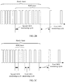
- FIG. 2A is a schematic diagram of a Gb architecture in an embodiment of the present invention.
- FIG. 2B is another schematic diagram of a Gb architecture in an embodiment of the present invention.
- FIG. 2C is another schematic diagram of a Gb architecture in an embodiment of the present invention.
- FIG. 2D is a schematic diagram of an S1 architecture in an embodiment of the present invention.
- FIG. 3 is a flowchart of monitoring downlink scheduling data in an embodiment of the present invention.
- FIG. 4 is a flowchart of sending downlink scheduling data in an embodiment of the present invention.
- FIG. 5A is a schematic structural diagram of a terminal in an embodiment of the present invention.
- FIG. 5B is another schematic structural diagram of a terminal in an embodiment of the present invention.
- FIG. 6A is a schematic structural diagram of a base station in an embodiment of the present invention.
- FIG. 6B is another schematic structural diagram of a base station in an embodiment of the present invention.
- GSM Global System for Mobile Communications
- CDMA Code Division Multiple Access
- TDMA Time Division Multiple Access
- WCDMA Wideband Code Division Multiple Access
- FDMA Frequency Division Multiple Access
- OFDMA Orthogonal Frequency Division Multiple Access
- SC-FDMA single-carrier FDMA
- GPRS general packet radio service
- the present invention may be applied to a Gb architecture, and only a ready timer may be used in the Gb architecture.
- a ready timer may be used in the Gb architecture.
- FIG. 2A in a scenario in which only the ready timer is used, within a time period in which the ready timer does not expire, downlink scheduling data is monitored by using a second DRX (Discontinuous Reception, discontinuous reception) monitoring cycle, and within a time period after the ready timer expires, the downlink scheduling data is monitored by using a first DRX monitoring cycle. Further, an RDR timer may be used. As shown in FIG.
- the downlink scheduling data is monitored by using the second DRX monitoring cycle, and within a time period after the ready timer expires, the downlink scheduling data is monitored by using the first DRX monitoring cycle.
- the RDR timer needs to stop even though the RDR timer does not expire.
- FIG. 2B a case in which the ready timer expires, but the RDR timer does not expire is described. Certainly, when the ready timer expires, the RDR timer may have expired. As shown in FIG.
- the downlink scheduling data is monitored by using the second DRX monitoring cycle; within a time period in which the ready timer does not expire, but the RDR timer expires, the downlink scheduling data is monitored by using a third DRX monitoring cycle; and within a time period after the ready timer expires, the downlink scheduling data is monitored by using the first DRX monitoring cycle.
- the first DRX monitoring cycle is in a unit of minute or hour, and both the second DRX monitoring cycle and the third DRX monitoring cycle are in a unit of millisecond or second.
- the second DRX monitoring cycle may be the same as or different from the third DRX monitoring cycle.
- the present invention may be applied to an S1 architecture, and only an RDR timer may be used in the S1 architecture.
- RDR timer within a time period in which the RDR timer does not expire, downlink scheduling data is monitored by using a second DRX monitoring cycle, and within a time period after the RDR timer expires, the downlink scheduling data is monitored by using a first DRX monitoring cycle.
- a ready timer is a timer that is maintained by both a terminal and a core network.
- the core network herein may refer to an Serving GPRS Support Node (SGSN) GPRS.
- the terminal starts the ready timer after sending a last uplink LLC data packet, and the core network starts the ready timer after receiving the last uplink LLC data packet.
- An RDR timer is a timer that is set by both a terminal and a base station. On a terminal side, the terminal starts the RDR timer after sending a last uplink MAC layer data packet and receiving positive feedback information for the MAC layer data packet from the base station.
- the terminal After a ready timer on the terminal side expires, if the RDR timer does not expire, the terminal stops the RDR timer, and releases a connection on the terminal side.
- the base station starts the RDR timer after receiving the last uplink MAC layer data packet sent by the terminal and sending the positive feedback information for the MAC layer data packet to the terminal.
- the Gb architecture after a base station receives a paging message delivered by a core network, if an RDR timer does not expire, the RDR timer stops, and a connection to a terminal is released. If the timer expires, the base station releases a connection to the terminal.
- the S1 architecture after an RDR timer expires, a base station initiates a connection release request to a core network, and the core network releases an S1 connection to a terminal, and the base station releases an air interface connection to the terminal.
- a procedure of monitoring downlink scheduling data is as follows:
- Step 300 Start a timer.
- Step 310 After it is determined that the timer expires, monitor, by using a first DRX monitoring cycle, downlink scheduling data sent by a base station.
- Duration of the first DRX monitoring cycle is in a unit of minute or hour.
- downlink scheduling data is monitored by using a DRX monitoring cycle whose duration is in a unit of second or millisecond, and consequently, power consumption is relatively large, and a relationship between power saving of a device and timely receiving of the downlink scheduling data cannot be balanced.
- the downlink scheduling data is monitored by using the first DRX monitoring cycle whose duration is in a unit of minute or hour, and in this way, not only power consumption is reduced, but also the downlink scheduling data can be monitored.
- the base station monitoring, by using the first DRX monitoring cycle according to a scheduling identifier in an idle state or a scheduling identifier in a connected state, the downlink scheduling data sent by the base station.
- the monitoring, by using a first DRX monitoring cycle, downlink scheduling data sent by a base station may include: monitoring, by using the first DRX monitoring cycle according to the scheduling identifier in an idle state, the downlink scheduling data sent by the base station.
- a terminal may return to a long sleep state in an idle state, or may be still in a long sleep state in a connected state.
- the monitoring, by using a first DRX monitoring cycle, downlink scheduling data sent by a base station may include: monitoring, by using the first DRX monitoring cycle according to the scheduling identifier in an idle state, the downlink scheduling data sent by the base station.
- the monitoring, by using a first DRX monitoring cycle, downlink scheduling data sent by a base station may include: monitoring, by using the first DRX monitoring cycle according to the scheduling identifier in a connected state, the downlink scheduling data sent by the base station.
- the method before the downlink scheduling data sent by the base station is monitored by using the first DRX monitoring cycle, the method further includes the following operation:
- the terminal may send the supported first DRX monitoring cycle to a core network device.
- the timer described in step 300 may include only a ready timer (Ready Timer).
- the ready timer is configured to determine that the terminal is switched from a ready state to a standby state. That is, before the ready timer expires, the terminal is in a ready state, and after the ready timer expires, the terminal is in a standby state.
- the starting a timer may include:
- the determining that the timer expires may include:
- an RDR timer (Timer) may be further included.
- the RDR timer is configured to determine that the terminal is switched from a connected state to a long sleep state. That is, when the RDR timer does not expire, the terminal is in a connected state, and after the RDR timer expires, the terminal is in a long sleep state.
- the long sleep state includes a long sleep state in an idle state or a long sleep state in a connected state.
- the starting a timer may include:
- the determining that the timer expires may include:
- the downlink scheduling data sent by the base station may be monitored by using the first DRX monitoring cycle provided that the ready timer expires. In this case, if the ready timer expires, but the RDR timer does not expire, the RDR timer needs to stop, and a connection is released.
- the timer includes only a ready timer, or includes both a ready timer and an RDR timer.
- the timer may include only an RDR timer.
- the starting a timer may include:
- the determining that the timer expires may include:
- the method further includes the following operations:
- DRX monitoring moment is a moment at a distance of N first DRX monitoring cycles from the initial monitoring moment, and N is a positive integer greater than or equal to 0.
- the following manner may be used:
- the method further includes the following operation:
- Duration of the second DRX monitoring cycle is in a unit of millisecond or second.
- the downlink scheduling data sent by the base station is monitored by using the first DRX monitoring cycle, and before the timer expires, the downlink scheduling data sent by the base station is monitored by using the second DRX monitoring cycle.
- the method further includes the following operation:
- the timer includes only a ready timer, or includes only an RDR timer, or includes both a ready timer and an RDR timer.
- the timer includes only a ready timer, or includes only an RDR timer, or includes both a ready timer and an RDR timer. The following separately gives description.
- the determining that the timer does not expire may include:
- the monitoring, by using a second DRX monitoring cycle, the downlink scheduling data sent by the base station may include:
- the base station monitoring, by using the second DRX monitoring cycle according to a scheduling identifier in an idle state, the downlink scheduling data sent by the base station.
- the determining that the timer does not expire may include:
- the downlink scheduling data sent by the base station may include:
- the base station monitoring, by using the second DRX monitoring cycle according to a scheduling identifier in a connected state, the downlink scheduling data sent by the base station.
- the starting a timer may include:
- the determining that the timer does not expire may include:
- the RDR timer may expire, or may not expire.
- the monitoring by using a second DRX monitoring cycle, the downlink scheduling data sent by the base station may include:
- the base station monitoring, by using the second DRX monitoring cycle according to a scheduling identifier in a connected state, the downlink scheduling data sent by the base station.
- the downlink scheduling data sent by the base station needs to be monitored by using a third DRX monitoring cycle according to a scheduling identifier in an idle state.
- Duration of the third DRX monitoring cycle is in a unit of millisecond or second.
- the second DRX monitoring cycle may be the same as or different from the third DRX monitoring cycle. This is not limited herein.
- the method before the downlink scheduling data sent by the base station is monitored by using the third DRX monitoring cycle, the method further includes the following operation:
- the ready timer is configured to determine that the terminal is switched from a ready state to a standby state
- the RDR timer is configured to determine that the terminal is switched from a connected state to a long sleep state
- the terminal When monitoring the downlink scheduling data, for example, after obtaining a paging radio network temporary identifier (P-RNTI) by means of monitoring, the terminal reads a paging record on a paging resource indicated by the P-RNTI. If there is a paging record that includes the identifier of the terminal, it indicates that the terminal is paged. If there is no paging record that includes the identifier of the terminal, it indicates that the terminal is not paged.
- P-RNTI paging radio network temporary identifier
- the downlink scheduling data is downlink data, or may be a paging message, and certainly, may be in another form. This is not limited herein.
- the method before the downlink scheduling data sent by the base station is monitored by using the first DRX monitoring cycle, the method further includes the following operations:
- the scheduling identifier in a connected state is in many forms, and optionally, may be a TBF (Temporary Block Flow, temporary block flow), or may be a C-RNTI (Cell Radio Network Temporary Identifier, cell radio network temporary identifier).
- TBF Temporary Block Flow, temporary block flow
- C-RNTI Cell Radio Network Temporary Identifier, cell radio network temporary identifier
- the scheduling identifier in an idle state is also in many forms, and optionally, may be a UE-dedicated scheduling identifier in an idle state, for example, a temporary logical link identifier (TLLI), an SAE temporary mobile subscriber identity (S-TMSI), system architecture evolution (SAE)), a PS temporary mobile subscriber identity (P-TMSI), packet switched (PS)), an international mobile subscriber identity (IMSI), or an IMSI mod N, or may be a common scheduling identifier in an idle state, for example, a paging radio network temporary identifier (P-RNTI).
- TLI temporary logical link identifier
- S-TMSI system architecture evolution
- P-TMSI PS temporary mobile subscriber identity
- PS packet switched
- IMSI international mobile subscriber identity
- IMSI mod N or may be a common scheduling identifier in an idle state, for example, a paging radio network temporary identifier (P-RNTI).
- P-RNTI paging radio network
- a procedure of sending downlink scheduling data is as follows:
- Step 400 Receive downlink scheduling data sent by a core network device to a terminal.
- Step 410 When it is determined that the terminal monitors the downlink scheduling data by using a first DRX monitoring cycle, send the downlink scheduling data to the terminal by using a first sending cycle.
- Duration of the first sending cycle is in a unit of minute or hour.
- the terminal monitors the downlink scheduling data by using the first DRX monitoring cycle.
- the downlink scheduling data directly carries the first DRX monitoring cycle, it may be directly determined, according to the first DRX monitoring cycle, that the terminal monitors the downlink scheduling data by using the first DRX monitoring cycle. If the downlink scheduling data does not carry the first DRX monitoring cycle, a type of the downlink scheduling data may be determined. If the type of the downlink scheduling data is a paging message, it is determined that the terminal monitors the downlink scheduling data by using the first DRX monitoring cycle.
- the terminal monitors the downlink scheduling data by using the first DRX monitoring cycle.
- an RDR timer in an S1 architecture expires, when the terminal is in a long sleep state in a connected state, it may be determined, by adding the first DRX monitoring cycle to the downlink scheduling data, that the terminal monitors the downlink scheduling data by using the first DRX monitoring cycle; or
- the terminal may be determined, by determining that the RDR timer expires, that the terminal monitors the downlink scheduling data by using the first DRX monitoring cycle.
- the method before the downlink scheduling data is sent to the terminal by using the first sending cycle, the method further includes the following operations:
- the terminal sending positive feedback information for the last uplink MAC layer data packet to the terminal, and starting an RDR timer, where the RDR timer is configured to determine that the terminal is switched from a connected state to a long sleep state.
- the following manner may be used to determine that the terminal monitors the downlink scheduling data by using the first discontinuous reception DRX monitoring cycle:
- the method before the downlink scheduling data is sent to the terminal by using the first sending cycle, the method further includes the following operations:
- the method before the downlink scheduling data is sent to the terminal by using the first sending cycle, the method further includes:
- DRX sending moment is a moment at a distance of N first sending cycles from the initial sending moment, and N is a positive integer greater than or equal to 0;
- the RDR timer is configured to determine that the terminal is switched from a connected state to an idle state.
- the foregoing manner of determining the DRX sending moment is applied to a case in which when an RDR timer expires in the S1 architecture, the terminal is still in a long sleep state in a connected state.
- the terminal monitors the downlink scheduling data by using the first DRX monitoring cycle.
- the terminal may monitor the downlink scheduling data by using a second DRX monitoring cycle.
- the base station needs to send the downlink scheduling data by using a second sending cycle corresponding to the second DRX monitoring cycle. Therefore, in this embodiment of the present invention, before it is determined that the terminal monitors the downlink scheduling data by using the first discontinuous reception DRX monitoring cycle, the method further includes the following operation:
- Duration of the second sending cycle is in a unit of millisecond or second.
- the terminal monitors the downlink scheduling data by using the second DRX monitoring cycle.
- the terminal may not monitor the downlink scheduling data by using the second DRX monitoring cycle. Further, when an RDR timer starts and does not expire, it is determined that the terminal monitors the downlink scheduling data by using the second DRX monitoring cycle. Therefore, in this embodiment of the present invention, before the downlink scheduling data is sent to the terminal by using the second sending cycle, the method further includes the following operations:
- the determining that the terminal monitors the downlink scheduling data by using a second DRX monitoring cycle includes:
- the terminal monitors the downlink scheduling data by using the second DRX monitoring cycle.
- the method before the downlink scheduling data is sent to the terminal by using the second sending cycle, the method further includes the following operations:
- the terminal monitors the downlink scheduling data by using a third DRX monitoring cycle. Therefore, in this embodiment of the present invention, before the downlink scheduling data is sent to the terminal by using the first sending cycle, the method further includes the following operation:
- Duration of the third sending cycle is from a millisecond range to a second range.
- the method before it is determined that the terminal monitors the downlink scheduling data by using the third DRX monitoring cycle, the method further includes the following operations:
- the determining that the terminal monitors the downlink scheduling data by using a third DRX monitoring cycle includes:
- the terminal monitors the downlink scheduling data by using the third DRX monitoring cycle.
- the method before it is determined that the terminal monitors the downlink scheduling data by using the third DRX monitoring cycle, the method further includes the following operations:
- the third sending cycle may be the same as or different from the second sending cycle. This is not limited herein.
- the first DRX monitoring cycle, the second DRX monitoring cycle, and the third DRX monitoring cycle that are sent by the base station to the terminal may be determined by the base station, or may be sent by a core network.
- the base station may be determined by the base station, or may be sent by a core network.
- another manner may be used, and this is not limited herein.
- the terminal includes a starting unit 50 , a determining unit 51 , and a monitoring unit 52 .
- the starting unit 50 is configured to start a timer.
- the determining unit 51 is configured to determine that the timer expires.
- the monitoring unit 52 is configured to: after the determining unit 51 determines that the timer expires, monitor, by using a first discontinuous reception DRX monitoring cycle, downlink scheduling data sent by a base station.
- Duration of the first DRX monitoring cycle is in a unit of minute or hour.
- the monitoring unit 52 is configured to:
- the downlink scheduling data sent by the base station monitor, by using the first DRX monitoring cycle according to a scheduling identifier in an idle state or a scheduling identifier in a connected state, the downlink scheduling data sent by the base station.
- the terminal further includes a receiving unit 53 .
- the receiving unit 53 is configured to receive a first DRX monitoring cycle that is sent by the base station in a broadcast manner or a dedicated signaling manner and that is supported by the base station, and the determining unit 51 is further configured to use the first DRX monitoring cycle supported by the base station as the first DRX monitoring cycle; or
- the receiving unit 53 is configured to receive a first DRX monitoring cycle that is sent by the base station in a broadcast manner or a dedicated signaling manner and that is supported by the base station, and the determining unit 51 is further configured to use a minimum DRX monitoring cycle or a maximum DRX monitoring cycle in the first DRX monitoring cycle supported by the base station and a first DRX monitoring cycle supported by the terminal as the first DRX monitoring cycle; or
- the determining unit 51 is further configured to use a first DRX monitoring cycle reported by the terminal as the first DRX monitoring cycle.
- the timer includes a ready timer (Ready Timer), and the ready timer is configured to determine that the terminal is switched from a ready state to a standby state.
- Ready Timer Ready Timer
- the timer further includes a reduced downlink control signal reception RDR timer, and the RDR timer is configured to determine that the terminal is switched from a connected state to a long sleep state.
- the starting unit 50 is configured to start the ready timer and the RDR timer, where a time of starting the ready timer is earlier than a time of starting the RDR timer.
- the determining unit 51 is configured to determine that the ready timer expires.
- the timer includes an RDR timer, and the RDR timer is configured to determine that the terminal is switched from a connected state to a long sleep state.
- the determining unit 51 is further configured to: determine an initial monitoring moment
- a DRX monitoring moment according to the initial monitoring moment, where the DRX monitoring moment is a moment at a distance of N first DRX monitoring cycles from the initial monitoring moment, and N is a positive integer greater than or equal to 0.
- the monitoring unit 52 is configured to monitor, at the DRX monitoring moment, the downlink scheduling data sent by the base station.
- determining unit 51 determines an initial monitoring moment
- the determining unit 51 is further configured to determine that the timer does not expire.
- the monitoring unit 52 is further configured to: when the determining unit 51 determines that the timer does not expire, monitor, by using a second DRX monitoring cycle, the downlink scheduling data sent by the base station.
- Duration of the second DRX monitoring cycle is in a unit of millisecond or second.
- the terminal further includes a receiving unit 53 .
- the receiving unit 53 is configured to receive a second DRX monitoring cycle that is sent by the base station in a broadcast manner or a dedicated signaling manner and that is supported by the base station, and the determining unit 51 is further configured to use the second DRX monitoring cycle supported by the base station as the second DRX monitoring cycle; or
- the receiving unit 53 is further configured to receive a second DRX monitoring cycle that is sent by the base station in a broadcast manner or a dedicated signaling manner and that is supported by the base station, and the determining unit 51 is further configured to use a minimum DRX monitoring cycle or a maximum DRX monitoring cycle in the second DRX monitoring cycle supported by the base station and a second DRX monitoring cycle supported by the terminal as the second DRX monitoring cycle; or
- the determining unit 51 is further configured to use a second DRX monitoring cycle reported by the terminal as the second DRX monitoring cycle.
- the timer includes a ready timer, and the ready timer is configured to determine that the terminal is switched from a ready state to a standby state.
- the monitoring unit 52 is configured to monitor, by using the second DRX monitoring cycle according to a scheduling identifier in an idle state, the downlink scheduling data sent by the base station.
- the timer includes an RDR timer, and the RDR timer is configured to determine that the terminal is switched from a connected state to a long sleep state.
- the monitoring unit 52 is configured to monitor, by using the second DRX monitoring cycle according to a scheduling identifier in a connected state, the downlink scheduling data sent by the base station.
- the timer includes a ready timer and an RDR timer
- the ready timer is configured to determine that the terminal is switched from a ready state to a standby state
- the RDR timer is configured to determine that the terminal is switched from a connected state to a long sleep state.
- the starting unit 50 is configured to start the ready timer and the RDR timer, where a time of starting the ready timer is earlier than a time of starting the RDR timer.
- That the determining unit 51 determines that the timer does not expire is:
- the determining unit 51 is further configured to determine that the RDR timer does not expire.
- the monitoring unit 52 is configured to monitor, by using the second DRX monitoring cycle according to a scheduling identifier in a connected state, the downlink scheduling data sent by the base station.
- the determining unit 51 is further configured to determine that the RDR timer expires.
- the monitoring unit 52 is further configured to monitor, by using a third DRX monitoring cycle according to a scheduling identifier in an idle state, the downlink scheduling data sent by the base station.
- Duration of the third DRX monitoring cycle is in a unit of millisecond or second.
- the terminal further includes a receiving unit 53 .
- the receiving unit 53 is configured to receive a third DRX monitoring cycle that is sent by the base station in a broadcast manner or a dedicated signaling manner and that is supported by the base station, and the determining unit 51 is further configured to use the third DRX monitoring cycle supported by the base station as the third DRX monitoring cycle; or
- the receiving unit 53 is further configured to receive a third DRX monitoring cycle that is sent by the base station in a broadcast manner or a dedicated signaling manner and that is supported by the base station, and the determining unit 51 is further configured to use a maximum DRX cycle or a minimum DRX cycle in the third DRX monitoring cycle supported by the base station and a third DRX monitoring cycle supported by the terminal as the third DRX monitoring cycle; or
- the determining unit 51 is further configured to use a third DRX monitoring cycle reported by the terminal as the third DRX monitoring cycle.
- the starting unit 50 is configured to start the ready timer and/or the RDR timer, the ready timer is configured to determine that the terminal is switched from a ready state to a standby state, and the RDR timer is configured to determine that the terminal is switched from a connected state to a long sleep state.
- the starting unit 50 starts the ready timer is:
- the terminal includes a processor 500 and a receiver 510 .
- the processor 500 is configured to start a timer.
- the processor 500 is further configured to determine that the timer expires.
- the receiver 510 is configured to: after the processor 500 determines that the timer expires, monitor, by using a first discontinuous reception DRX monitoring cycle, downlink scheduling data sent by a base station.
- Duration of the first DRX monitoring cycle is in a unit of minute or hour.
- the processor 500 may further perform other operations performed by the starting unit 50 and the determining unit 51 that are shown in FIG. 5A
- the receiver 510 may further perform other operations performed by the monitoring unit 52 and the receiving unit 53 that are shown in FIG. 5A .
- the base station includes a receiving unit 60 , a determining unit 61 , and a sending unit 62 .
- the receiving unit 60 is configured to receive downlink scheduling data sent by a core network device to a terminal.
- the determining unit 61 is configured to determine that the terminal monitors the downlink scheduling data by using a first discontinuous reception DRX monitoring cycle.
- the sending unit 62 is configured to: when the determining unit 61 determines that the terminal monitors the downlink scheduling data by using the first discontinuous reception DRX monitoring cycle, send the downlink scheduling data to the terminal by using a first sending cycle.
- Duration of the first sending cycle is in a unit of minute or hour.
- the determining unit 61 is configured to: determine, according to the first DRX monitoring cycle carried in the downlink scheduling data, that the terminal monitors the downlink scheduling data by using the first DRX monitoring cycle; or
- the terminal when determining that the downlink scheduling data is a paging message, determine that the terminal monitors the downlink scheduling data by using the first DRX monitoring cycle.
- the receiving unit 60 is further configured to receive a last uplink MAC layer data packet sent by the terminal.
- the sending unit 62 is further configured to send positive feedback information for the last uplink MAC layer data packet to the terminal.
- the base station further includes a starting unit 63 , configured to start a reduced downlink control signal reception RDR timer when the sending unit 62 sends the positive feedback information for the last uplink MAC layer data packet to the terminal, where the RDR timer is configured to determine that the terminal is switched from a connected state to a long sleep state.
- a starting unit 63 configured to start a reduced downlink control signal reception RDR timer when the sending unit 62 sends the positive feedback information for the last uplink MAC layer data packet to the terminal, where the RDR timer is configured to determine that the terminal is switched from a connected state to a long sleep state.
- the determining unit 61 is configured to: when determining that the RDR timer expires, determine that the terminal monitors the downlink scheduling data by using the first DRX monitoring cycle.
- the sending unit 62 is further configured to: send the first DRX monitoring cycle to the terminal in a broadcast manner or a dedicated signaling manner; or send, in a broadcast manner or a dedicated signaling manner, a first DRX monitoring cycle supported by the base station to the terminal; and/or
- the determining unit 61 is further configured to: determine an initial sending moment; and determine a DRX sending moment according to the initial sending moment, where the DRX sending moment is a moment at a distance of N first sending cycles from the initial sending moment, and N is a positive integer greater than or equal to 0.
- the sending unit 62 is configured to send the downlink scheduling data at the DRX sending moment.
- determining unit 61 determines an initial sending moment
- the RDR timer is configured to determine that the terminal is switched from a connected state to a long sleep state.
- the determining unit 61 is further configured to determine that the terminal monitors the downlink scheduling data by using a second DRX monitoring cycle.
- the sending unit 62 is further configured to send the downlink scheduling data to the terminal by using a second sending cycle.
- Duration of the second sending cycle is in a unit of millisecond or second.
- the determining unit 61 determines that the terminal monitors the downlink scheduling data by using a second DRX monitoring cycle is:
- the terminal when determining that the downlink scheduling data is downlink data, determining that the terminal monitors the downlink scheduling data by using the second DRX monitoring cycle.
- the receiving unit 60 is further configured to receive a last uplink MAC layer data packet sent by the terminal.
- the sending unit 62 is further configured to send positive feedback information for the last uplink MAC layer data packet to the terminal.
- the base station further includes a starting unit 63 , configured to start an RDR timer when the sending unit 62 sends the positive feedback information for the last uplink MAC layer data packet to the terminal, where the RDR timer is configured to determine that the terminal is switched from a connected state to a long sleep state.
- That the determining unit 61 determines that the terminal monitors the downlink scheduling data by using a second DRX monitoring cycle is:
- the sending unit 62 is further configured to: send the second DRX monitoring cycle to the terminal in a broadcast manner or a dedicated signaling manner; or send, in a broadcast manner or a dedicated signaling manner, a second DRX monitoring cycle supported by the base station to the terminal; and/or
- the determining unit 61 is further configured to determine that the terminal monitors the downlink scheduling data by using a third DRX monitoring cycle.
- the sending unit 62 is further configured to: when the determining unit 61 determines that the terminal monitors the downlink scheduling data by using the third DRX monitoring cycle, send the downlink scheduling data to the terminal by using a third sending cycle.
- Duration of the third sending cycle is from a millisecond range to a second range.
- the receiving unit 60 is further configured to receive a last uplink MAC layer data packet sent by the terminal.
- the sending unit 62 is further configured to send positive feedback information for the last uplink MAC layer data packet to the terminal.
- the base station further includes a starting unit 63 , configured to start an RDR timer when the sending unit 62 sends the positive feedback information for the last uplink MAC layer data packet to the terminal, where the RDR timer is configured to determine that the terminal is switched from a connected state to a long sleep state.
- That the determining unit 61 determines that the terminal monitors the downlink scheduling data by using a third DRX monitoring cycle is:
- the sending unit 62 is further configured to: send the third DRX monitoring cycle to the terminal in a broadcast manner or a dedicated signaling manner; and/or
- the base station includes a receiver 600 , a processor 610 , and a transmitter 620 .
- the receiver 600 is configured to receive downlink scheduling data sent by a core network device to the terminal.
- the processor 610 is configured to determine that the terminal monitors the downlink scheduling data by using a first discontinuous reception DRX monitoring cycle.
- the transmitter 620 is configured to: when the processor 610 determines that the terminal monitors the downlink scheduling data by using the first discontinuous reception DRX monitoring cycle, send the downlink scheduling data to the terminal by using a first sending cycle.
- Duration of the first sending cycle is in a unit of minute or hour.
- the receiver 600 may further perform other operations performed by the receiving unit 60 shown in FIG. 6A
- the processor 610 may further perform other operations performed by the determining unit 61 and the starting unit 63 that are shown in FIG. 6A
- the transmitter 620 may further perform other operations performed by the sending unit 62 shown in FIG. 6A .
- These computer program instructions may be provided for a general-purpose computer, a dedicated computer, an embedded processor, or a processor of any other programmable data processing device to generate a machine, so that the instructions executed by a computer or a processor of any other programmable data processing device generate an apparatus for implementing a specific function in one or more processes in the flowcharts and/or in one or more blocks in the block diagrams.
- These computer program instructions may also be stored in a computer readable memory that can instruct the computer or any other programmable data processing device to work in a specific manner, so that the instructions stored in the computer readable memory generate an artifact that includes an instruction apparatus.
- the instruction apparatus implements a specific function in one or more processes in the flowcharts and/or in one or more blocks in the block diagrams.
- These computer program instructions may also be loaded onto a computer or another programmable data processing device, so that a series of operations and steps are performed on the computer or the another programmable device, thereby generating computer-implemented processing. Therefore, the instructions executed on the computer or the another programmable device provide steps for implementing a specific function in one or more processes in the flowcharts and/or in one or more blocks in the block diagrams.
Landscapes
- Engineering & Computer Science (AREA)
- Computer Networks & Wireless Communication (AREA)
- Signal Processing (AREA)
- Mobile Radio Communication Systems (AREA)
- Transceivers (AREA)
- Circuits Of Receivers In General (AREA)
Priority Applications (2)
| Application Number | Priority Date | Filing Date | Title |
|---|---|---|---|
| US16/885,306 US11350362B2 (en) | 2015-05-19 | 2020-05-28 | Downlink scheduling data monitoring method, downlink scheduling data sending method, and apparatus |
| US17/737,671 US11785542B2 (en) | 2015-05-19 | 2022-05-05 | Downlink scheduling data monitoring method, downlink scheduling data sending method, and apparatus |
Applications Claiming Priority (4)
| Application Number | Priority Date | Filing Date | Title |
|---|---|---|---|
| CN201510257300.2 | 2015-05-19 | ||
| CN201510257300 | 2015-05-19 | ||
| CN201510257300.2A CN106304129B (zh) | 2015-05-19 | 2015-05-19 | 一种监听及发送下行调度数据的方法及装置 |
| PCT/CN2016/075805 WO2016184224A1 (zh) | 2015-05-19 | 2016-03-07 | 一种监听及发送下行调度数据的方法及装置 |
Related Parent Applications (1)
| Application Number | Title | Priority Date | Filing Date |
|---|---|---|---|
| PCT/CN2016/075805 Continuation WO2016184224A1 (zh) | 2015-05-19 | 2016-03-07 | 一种监听及发送下行调度数据的方法及装置 |
Related Child Applications (1)
| Application Number | Title | Priority Date | Filing Date |
|---|---|---|---|
| US16/885,306 Continuation US11350362B2 (en) | 2015-05-19 | 2020-05-28 | Downlink scheduling data monitoring method, downlink scheduling data sending method, and apparatus |
Publications (2)
| Publication Number | Publication Date |
|---|---|
| US20180110005A1 US20180110005A1 (en) | 2018-04-19 |
| US10694462B2 true US10694462B2 (en) | 2020-06-23 |
Family
ID=57319287
Family Applications (3)
| Application Number | Title | Priority Date | Filing Date |
|---|---|---|---|
| US15/817,266 Active 2036-04-10 US10694462B2 (en) | 2015-05-19 | 2017-11-19 | Downlink scheduling data monitoring method, downlink scheduling data sending method, and apparatus |
| US16/885,306 Active 2036-04-03 US11350362B2 (en) | 2015-05-19 | 2020-05-28 | Downlink scheduling data monitoring method, downlink scheduling data sending method, and apparatus |
| US17/737,671 Active US11785542B2 (en) | 2015-05-19 | 2022-05-05 | Downlink scheduling data monitoring method, downlink scheduling data sending method, and apparatus |
Family Applications After (2)
| Application Number | Title | Priority Date | Filing Date |
|---|---|---|---|
| US16/885,306 Active 2036-04-03 US11350362B2 (en) | 2015-05-19 | 2020-05-28 | Downlink scheduling data monitoring method, downlink scheduling data sending method, and apparatus |
| US17/737,671 Active US11785542B2 (en) | 2015-05-19 | 2022-05-05 | Downlink scheduling data monitoring method, downlink scheduling data sending method, and apparatus |
Country Status (6)
| Country | Link |
|---|---|
| US (3) | US10694462B2 (de) |
| EP (2) | EP4615115A3 (de) |
| JP (2) | JP6510076B2 (de) |
| CN (2) | CN106304129B (de) |
| MX (1) | MX381656B (de) |
| WO (1) | WO2016184224A1 (de) |
Cited By (1)
| Publication number | Priority date | Publication date | Assignee | Title |
|---|---|---|---|---|
| US11350362B2 (en) * | 2015-05-19 | 2022-05-31 | Huawei Technologies Co., Ltd. | Downlink scheduling data monitoring method, downlink scheduling data sending method, and apparatus |
Families Citing this family (9)
| Publication number | Priority date | Publication date | Assignee | Title |
|---|---|---|---|---|
| CN109246801B (zh) * | 2017-05-04 | 2022-01-25 | 成都鼎桥通信技术有限公司 | 空闲监听态终端实现非连续接收的方法及装置 |
| CN109246625B (zh) * | 2017-06-07 | 2022-04-26 | 成都鼎桥通信技术有限公司 | 集群非连续接收调度方法和系统 |
| WO2019028760A1 (zh) * | 2017-08-10 | 2019-02-14 | 富士通株式会社 | 资源指示和接收方法、装置及通信系统 |
| CN109982416B (zh) * | 2017-12-27 | 2022-04-12 | 珠海市魅族科技有限公司 | 一种数据接收及发送的方法及装置 |
| US12343563B2 (en) * | 2018-05-07 | 2025-07-01 | Dalhousie University | Systems and methods for planning, controlling and/or delivering radiotherapy and radiosurgery using combined optimization of dynamic axes (CODA) |
| EP3837915A1 (de) | 2018-09-28 | 2021-06-23 | Sony Corporation | Verfahren, kommunikationsvorrichtung und infrastrukturausrüstung |
| CN111132276B (zh) * | 2018-10-31 | 2021-10-01 | 华为技术有限公司 | 无线通信方法及终端设备 |
| US11690123B2 (en) * | 2020-02-12 | 2023-06-27 | Qualcomm Incorporated | Data inactivity indication and expedited recovery action |
| CN113905406B (zh) * | 2020-06-22 | 2024-10-22 | 大唐移动通信设备有限公司 | 一种信号传输方法及设备 |
Citations (23)
| Publication number | Priority date | Publication date | Assignee | Title |
|---|---|---|---|---|
| US20100034142A1 (en) | 2008-08-11 | 2010-02-11 | Motorola, Inc. | Method and apparatus for adjusting an on duration in a discontinuous receive transmission mode |
| CN101675610A (zh) | 2007-05-01 | 2010-03-17 | Lg电子株式会社 | 数据传送/接收方法 |
| US20110269462A1 (en) * | 2010-04-30 | 2011-11-03 | Saegfors Mats | Method, apparatus and system for mobility enhancement in drx |
| US20130136072A1 (en) | 2010-03-26 | 2013-05-30 | Panasonic Corporation | Group-based paging for machine-type-communication (mtc) devices |
| US20130223307A1 (en) | 2012-02-24 | 2013-08-29 | Telefonaktiebolaget Lm Ericsson (Publ) | Combating drx deadlock in telecommunications |
| US20130301501A1 (en) | 2012-05-09 | 2013-11-14 | Interdigital Patent Holdings, Inc. | Methods and apparatus for handling mtc long drx cycle/sleep lengths |
| US20130308465A1 (en) * | 2012-05-18 | 2013-11-21 | Qualcomm Incorporated | Method and apparatus for joint harq and drx optimization for low cost mtc devices |
| US20130315122A1 (en) * | 2011-08-01 | 2013-11-28 | Alexander Sasha Sirotkin | Extended Discontinuous Reception Cycle for Wireless Devices |
| US20140119255A1 (en) * | 2011-07-01 | 2014-05-01 | Rath Vannithamby | User equipment and method for quality of experience based discontinuous reception in lte-a networks |
| US20140286215A1 (en) | 2012-11-01 | 2014-09-25 | Ali Taha Koc | Extended discontinuous reception (drx) cycle length in wireless communication networks |
| US20140307606A1 (en) | 2008-04-25 | 2014-10-16 | Blackberry Limited | Method and system for the control of discontinuous reception in a wireless network |
| US20150055532A1 (en) * | 2012-12-10 | 2015-02-26 | Telefonaktiebolaget L M Ericsson (Publ) | Wireless device, a radio network node and methods for discontinuous reception in device to device communications |
| WO2015065041A1 (en) | 2013-11-01 | 2015-05-07 | Lg Electronics Inc. | Method and apparatus for transmitting paging message in wireless communication system |
| US20150173122A1 (en) * | 2013-08-22 | 2015-06-18 | Telefonaktiebolaget L M Ericsson (Publ) | Mobile station, core network node, base station subsystem, and methods for implementing longer paging cycles in a cellular network |
| US20150282076A1 (en) * | 2012-10-29 | 2015-10-01 | Telefonaktiebolaget L M Ericsson (Publ) | Wake-Up for Measurements During DRX Cycles |
| US20160057738A1 (en) * | 2013-05-09 | 2016-02-25 | Lg Electronics Inc. | Method for monitoring paging occasions in a wireless communication system and device therefor |
| US20160227601A1 (en) * | 2012-11-27 | 2016-08-04 | Nec Corporation | Discontinuous reception in a mobile radio communication device |
| US20160262130A1 (en) * | 2015-03-05 | 2016-09-08 | Telefonaktiebolaget Lm Ericsson (Publ) | Signaling of core network restart to wireless devices |
| US20160345380A1 (en) * | 2015-05-19 | 2016-11-24 | Telefonaktiebolaget LM Ericssion (publ) | RADIO ACCESS NETWORK NODE AND METHOD - TIME COORDINATED CELLS FOR EXTENDED DISCONTINUOUS RECEIVE (eDRX) |
| EP2774423B1 (de) | 2011-11-04 | 2017-05-31 | Intel Corporation | Reduzierung eines drahtlosen stromverbrauchs und eines signalisierungsoverheads für nachrichten im hintergrund einer internetanwendung |
| US20170367050A1 (en) * | 2015-03-03 | 2017-12-21 | Kyocera Corporation | Base station, apparatus and communication method |
| US20170367045A1 (en) * | 2014-12-17 | 2017-12-21 | Telefonaktiebolaget Lm Ericsson (Publ) | Handling interruptions during drx on durations |
| US10051570B2 (en) * | 2014-11-06 | 2018-08-14 | Sierra Wireless, Inc. | Method and apparatus for communication of system information in a wireless system |
Family Cites Families (8)
| Publication number | Priority date | Publication date | Assignee | Title |
|---|---|---|---|---|
| WO2007148930A1 (en) * | 2006-06-21 | 2007-12-27 | Electronics And Telecommunications Research Institute | Method to transmit downlink signaling message on cellular systems for packet transmission and method for receiving the message |
| JP5720215B2 (ja) * | 2010-12-06 | 2015-05-20 | ソニー株式会社 | ゲートウェイ装置および通信方法 |
| EP3125617B1 (de) * | 2011-12-02 | 2019-07-03 | Sony Corporation | Kommunikationsendgerät, kommunikationsverfahren, basisstation und kommunikationssystem |
| WO2013164025A1 (en) * | 2012-05-03 | 2013-11-07 | Telefonaktiebolaget L M Ericsson (Publ) | Telecommunication systems with discontinuous reception |
| CN103889039B (zh) * | 2014-04-18 | 2017-05-10 | 大唐移动通信设备有限公司 | 基于非连续接收功能的省电方法及设备 |
| EP3627961B1 (de) * | 2015-03-25 | 2021-05-26 | LG Electronics Inc. | Verfahren zur überwachung der erreichbarkeit einer benutzervorrichtung in einem drahtloskommunikationssystem und vorrichtung dafür |
| EP3281490B1 (de) * | 2015-04-10 | 2019-10-23 | INTEL Corporation | Drx in einem gerät mit bereit status |
| CN106304129B (zh) * | 2015-05-19 | 2020-02-14 | 华为技术有限公司 | 一种监听及发送下行调度数据的方法及装置 |
-
2015
- 2015-05-19 CN CN201510257300.2A patent/CN106304129B/zh active Active
- 2015-05-19 CN CN202010071996.0A patent/CN111263336A/zh active Pending
-
2016
- 2016-03-07 MX MX2017014836A patent/MX381656B/es unknown
- 2016-03-07 WO PCT/CN2016/075805 patent/WO2016184224A1/zh not_active Ceased
- 2016-03-07 EP EP25173530.4A patent/EP4615115A3/de active Pending
- 2016-03-07 EP EP16795711.7A patent/EP3288317B1/de active Active
- 2016-03-07 JP JP2017560225A patent/JP6510076B2/ja active Active
-
2017
- 2017-11-19 US US15/817,266 patent/US10694462B2/en active Active
-
2019
- 2019-04-03 JP JP2019071505A patent/JP7150657B2/ja active Active
-
2020
- 2020-05-28 US US16/885,306 patent/US11350362B2/en active Active
-
2022
- 2022-05-05 US US17/737,671 patent/US11785542B2/en active Active
Patent Citations (32)
| Publication number | Priority date | Publication date | Assignee | Title |
|---|---|---|---|---|
| CN101675610A (zh) | 2007-05-01 | 2010-03-17 | Lg电子株式会社 | 数据传送/接收方法 |
| US20110039536A1 (en) | 2007-05-01 | 2011-02-17 | Lg Electronics Inc. | Data transmission/reception method |
| US20140307606A1 (en) | 2008-04-25 | 2014-10-16 | Blackberry Limited | Method and system for the control of discontinuous reception in a wireless network |
| US20100034142A1 (en) | 2008-08-11 | 2010-02-11 | Motorola, Inc. | Method and apparatus for adjusting an on duration in a discontinuous receive transmission mode |
| US20130136072A1 (en) | 2010-03-26 | 2013-05-30 | Panasonic Corporation | Group-based paging for machine-type-communication (mtc) devices |
| JP2013524563A (ja) | 2010-03-26 | 2013-06-17 | パナソニック株式会社 | マシン・タイプ・コミュニケーション(mtc)デバイス用のグループベースのページング |
| US20110269462A1 (en) * | 2010-04-30 | 2011-11-03 | Saegfors Mats | Method, apparatus and system for mobility enhancement in drx |
| US20140119255A1 (en) * | 2011-07-01 | 2014-05-01 | Rath Vannithamby | User equipment and method for quality of experience based discontinuous reception in lte-a networks |
| US20130315122A1 (en) * | 2011-08-01 | 2013-11-28 | Alexander Sasha Sirotkin | Extended Discontinuous Reception Cycle for Wireless Devices |
| CN103843415A (zh) | 2011-08-01 | 2014-06-04 | 英特尔公司 | 无线装置的扩展不连续接收循环 |
| EP2774423B1 (de) | 2011-11-04 | 2017-05-31 | Intel Corporation | Reduzierung eines drahtlosen stromverbrauchs und eines signalisierungsoverheads für nachrichten im hintergrund einer internetanwendung |
| US20130223307A1 (en) | 2012-02-24 | 2013-08-29 | Telefonaktiebolaget Lm Ericsson (Publ) | Combating drx deadlock in telecommunications |
| CN104303586A (zh) | 2012-05-09 | 2015-01-21 | 交互数字专利控股公司 | 处理mtc长drx周期/睡眠长度 |
| US20130301501A1 (en) | 2012-05-09 | 2013-11-14 | Interdigital Patent Holdings, Inc. | Methods and apparatus for handling mtc long drx cycle/sleep lengths |
| US20180302946A1 (en) * | 2012-05-09 | 2018-10-18 | Interdigital Patent Holdings, Inc. | Methods and Apparatus for Handling MTC Long DRX Cycle/Sleep Lengths |
| US20130308465A1 (en) * | 2012-05-18 | 2013-11-21 | Qualcomm Incorporated | Method and apparatus for joint harq and drx optimization for low cost mtc devices |
| US20150282076A1 (en) * | 2012-10-29 | 2015-10-01 | Telefonaktiebolaget L M Ericsson (Publ) | Wake-Up for Measurements During DRX Cycles |
| US10051565B2 (en) * | 2012-10-29 | 2018-08-14 | Telefonaktiebolaget L M Ericsson (Publ) | Wake-up for measurements during DRX cycles |
| US20140286215A1 (en) | 2012-11-01 | 2014-09-25 | Ali Taha Koc | Extended discontinuous reception (drx) cycle length in wireless communication networks |
| US20160227601A1 (en) * | 2012-11-27 | 2016-08-04 | Nec Corporation | Discontinuous reception in a mobile radio communication device |
| US20150055532A1 (en) * | 2012-12-10 | 2015-02-26 | Telefonaktiebolaget L M Ericsson (Publ) | Wireless device, a radio network node and methods for discontinuous reception in device to device communications |
| US20160057738A1 (en) * | 2013-05-09 | 2016-02-25 | Lg Electronics Inc. | Method for monitoring paging occasions in a wireless communication system and device therefor |
| US20150173122A1 (en) * | 2013-08-22 | 2015-06-18 | Telefonaktiebolaget L M Ericsson (Publ) | Mobile station, core network node, base station subsystem, and methods for implementing longer paging cycles in a cellular network |
| WO2015065041A1 (en) | 2013-11-01 | 2015-05-07 | Lg Electronics Inc. | Method and apparatus for transmitting paging message in wireless communication system |
| JP2016535506A (ja) | 2013-11-01 | 2016-11-10 | エルジー エレクトロニクス インコーポレイティド | 無線通信システムにおけるページングメッセージを送信する方法及び装置 |
| US20160270028A1 (en) | 2013-11-01 | 2016-09-15 | Lg Electronics Inc. | Method and apparatus for transmitting paging message in wireless communication system |
| US10051570B2 (en) * | 2014-11-06 | 2018-08-14 | Sierra Wireless, Inc. | Method and apparatus for communication of system information in a wireless system |
| US20170367045A1 (en) * | 2014-12-17 | 2017-12-21 | Telefonaktiebolaget Lm Ericsson (Publ) | Handling interruptions during drx on durations |
| US20170367050A1 (en) * | 2015-03-03 | 2017-12-21 | Kyocera Corporation | Base station, apparatus and communication method |
| US10531386B2 (en) * | 2015-03-03 | 2020-01-07 | Kyocera Corporation | Base station, apparatus and communication method for retransmitting paging message addressed to radio terminal |
| US20160262130A1 (en) * | 2015-03-05 | 2016-09-08 | Telefonaktiebolaget Lm Ericsson (Publ) | Signaling of core network restart to wireless devices |
| US20160345380A1 (en) * | 2015-05-19 | 2016-11-24 | Telefonaktiebolaget LM Ericssion (publ) | RADIO ACCESS NETWORK NODE AND METHOD - TIME COORDINATED CELLS FOR EXTENDED DISCONTINUOUS RECEIVE (eDRX) |
Non-Patent Citations (14)
| Title |
|---|
| 3GPP TS 23.060 V13.2.0 (Mar. 2015),3rd Generation Partnership Project;Technical Specification Group Services and Systems Aspects;General Packet Radio Service (GPRS);Service description;Stage 2(Release 13),total 355 pages. |
| 3GPP TS 23.682 V13.1.0 (Mar. 2015),3rd Generation Partnership Project;Technical Specification Group Services and System Aspects;Architecture enhancements to facilitate communications with packet data networks and applications (Release 13),total 35 pages. |
| 3GPP TS 24.008 V13.1.0 (Mar. 2015),3rd Generation Partnership Project;Technical Specification Group Core Network and Terminals;Mobile radio interface Layer 3 specification;Core network protocols; Stage 3(Release 13),total 714 pages. |
| 3GPP TS 36.300 V12.5.0 (Mar. 2015),3rd Generation Partnership Project;Technical Specification Group Radio Access Network;Evolved Universal Terrestrial Radio Access (E-UTRA) and Evolved Universal Terrestrial Radio Access Network (E-UTRAN);Overall description; Stage 2(Release 12),total 251 pages. |
| 3GPP TS 36.304 V12.4.0 (Mar. 2015),3rd Generation Partnership Project;Technical Specification Group Radio Access Network;Evolved Universal Terrestrial Radio Access (E-UTRA); User Equipment (UE) procedures in idle mode (Release 12),total 38 pages. |
| 3GPP TS 36.331 V12.5.0 (Mar. 2015),3rd Generation Partnership Project;Technical Specification Group Radio Access Network;Evolved Universal Terrestrial Radio Access (E-UTRA);Radio Resource Control (RRC);Protocol specification (Release 12),total 445 pages. |
| 3GPP TS 36.413 V12.5.0 (Mar. 2015),3rd Generation Partnership Project;Technical Specification Group Radio Access Network;Evolved Universal Terrestrial Radio Access Network(E-UTRAN);S1 Application Protocol (S1AP)(Release 12), total 301 pages. |
| 3GPP TS 44.018 V12.5.0 (Mar. 2015),3rd Generation Partnership Project;Technical Specification Group GSM/EDGE Radio Access Network;Mobile radio interface layer 3 specification;Radio Resource Control (RRC) protocol(Release 12),total 472 pages. |
| 3GPP TS 44.060 V12.4.1 (Apr. 2015),3rd Generation Partnership Project;Technical Specification Group GSM/EDGE Radio Access Network;General Packet Radio Service (GPRS);Mobile Station (MS)-Base Station System (BSS) interface;Radio Link Control / Medium Access Control (RLC/MAC) protocol(Release 12),total 677 pages. |
| 3GPP TS 44.060 V12.4.1 (Apr. 2015),3rd Generation Partnership Project;Technical Specification Group GSM/EDGE Radio Access Network;General Packet Radio Service (GPRS);Mobile Station (MS)—Base Station System (BSS) interface;Radio Link Control / Medium Access Control (RLC/MAC) protocol(Release 12),total 677 pages. |
| 3GPP TS 45.002 V12.4.0 (Mar. 2015),3rd Generation Partnership Project;Technical Specification Group GSM/EDGE Radio Access Network;Multiplexing and multiple access on the radio path(Release 12),total 119 pages. |
| 3GPP TS 48.018 V12.4.0 (Nov. 2014),3rd Generation Partnership Project;Technical Specification Group GSM/EDGE Radio Access Network;General Packet Radio Service (GPRS);Base Station System (BSS)-Serving GPRS Support Node (SGSN);BSS GPRS Protocol (BSSGP)(Release 12),total 190 pages. |
| 3GPP TS 48.018 V12.4.0 (Nov. 2014),3rd Generation Partnership Project;Technical Specification Group GSM/EDGE Radio Access Network;General Packet Radio Service (GPRS);Base Station System (BSS)—Serving GPRS Support Node (SGSN);BSS GPRS Protocol (BSSGP)(Release 12),total 190 pages. |
| R2-152638 Alcatel-Lucent et al.,"Supporting eCDRX in RRC connected state", 3GPP TSG-RAN WG2 Meeting #90, Fukuoka, Japan, May 25-29, 2015, total 4 pages. |
Cited By (3)
| Publication number | Priority date | Publication date | Assignee | Title |
|---|---|---|---|---|
| US11350362B2 (en) * | 2015-05-19 | 2022-05-31 | Huawei Technologies Co., Ltd. | Downlink scheduling data monitoring method, downlink scheduling data sending method, and apparatus |
| US20220264457A1 (en) * | 2015-05-19 | 2022-08-18 | Huawei Technologies Co., Ltd. | Downlink scheduling data monitoring method, downlink scheduling data sending method, and apparatus |
| US11785542B2 (en) * | 2015-05-19 | 2023-10-10 | Huawei Technologies Co., Ltd. | Downlink scheduling data monitoring method, downlink scheduling data sending method, and apparatus |
Also Published As
| Publication number | Publication date |
|---|---|
| WO2016184224A1 (zh) | 2016-11-24 |
| US20200367162A1 (en) | 2020-11-19 |
| MX2017014836A (es) | 2018-03-14 |
| JP2018516012A (ja) | 2018-06-14 |
| EP4615115A3 (de) | 2025-12-10 |
| MX381656B (es) | 2025-03-13 |
| EP3288317A4 (de) | 2018-08-29 |
| US20220264457A1 (en) | 2022-08-18 |
| JP6510076B2 (ja) | 2019-05-08 |
| US11785542B2 (en) | 2023-10-10 |
| EP3288317B1 (de) | 2025-05-21 |
| CN106304129A (zh) | 2017-01-04 |
| JP7150657B2 (ja) | 2022-10-11 |
| JP2019118147A (ja) | 2019-07-18 |
| US11350362B2 (en) | 2022-05-31 |
| US20180110005A1 (en) | 2018-04-19 |
| EP3288317A1 (de) | 2018-02-28 |
| CN111263336A (zh) | 2020-06-09 |
| EP4615115A2 (de) | 2025-09-10 |
| CN106304129B (zh) | 2020-02-14 |
Similar Documents
| Publication | Publication Date | Title |
|---|---|---|
| US11785542B2 (en) | Downlink scheduling data monitoring method, downlink scheduling data sending method, and apparatus | |
| US20230413375A1 (en) | Pre-configured dedicated resource for idle mode transmissions | |
| US9369961B2 (en) | User equipment, cellular communication network node and method of controlling operation of a user equipment | |
| EP2575382A1 (de) | Verfahren zum Zuweisen von Ressourcen in einem drahtlosen Breitbandzugangssystem | |
| EP2632213B1 (de) | Verfahren und vorrichtung zur durchführung einer netzwerk-eingabe/-neueingabe in einem drahtlosen kommunikationssystem | |
| US9161177B2 (en) | Method for transmitting and receiving multicast-data-related information by a machine-to-machine (M2M) device in a wireless communication system, and apparatus therefor | |
| JP5603503B2 (ja) | マルチキャストトラフィック送受信のためのm2m機器及び基地局、及びその実行方法 | |
| US9344859B2 (en) | Method of receiving multicast data in a wireless communication system, and device for same | |
| US9125026B2 (en) | Method for receiving multicast data in wireless communication system and M2M device therefor | |
| US10187871B2 (en) | Paging method and device for network and terminal | |
| CN109246801B (zh) | 空闲监听态终端实现非连续接收的方法及装置 | |
| US10237825B2 (en) | Data processing apparatus and method | |
| CN112867106B (zh) | 通信方法、系统以及无线接入点 | |
| KR20120089038A (ko) | 단말에 따른 무선 자원 제어 상태 제어 시스템 및 방법 | |
| WO2016165079A1 (zh) | 一种监听下行控制信息的方法、装置和系统 | |
| KR20140042822A (ko) | M2m 환경을 지원하는 무선접속시스템에서 방송 메시지 전송 방법 및 장치 |
Legal Events
| Date | Code | Title | Description |
|---|---|---|---|
| FEPP | Fee payment procedure |
Free format text: ENTITY STATUS SET TO UNDISCOUNTED (ORIGINAL EVENT CODE: BIG.); ENTITY STATUS OF PATENT OWNER: LARGE ENTITY |
|
| STPP | Information on status: patent application and granting procedure in general |
Free format text: NON FINAL ACTION MAILED |
|
| STPP | Information on status: patent application and granting procedure in general |
Free format text: RESPONSE TO NON-FINAL OFFICE ACTION ENTERED AND FORWARDED TO EXAMINER |
|
| STPP | Information on status: patent application and granting procedure in general |
Free format text: FINAL REJECTION MAILED |
|
| STPP | Information on status: patent application and granting procedure in general |
Free format text: ADVISORY ACTION MAILED |
|
| STPP | Information on status: patent application and granting procedure in general |
Free format text: RESPONSE AFTER FINAL ACTION FORWARDED TO EXAMINER |
|
| STPP | Information on status: patent application and granting procedure in general |
Free format text: NOTICE OF ALLOWANCE MAILED -- APPLICATION RECEIVED IN OFFICE OF PUBLICATIONS |
|
| AS | Assignment |
Owner name: HUAWEI TECHNOLOGIES CO., LTD., CHINA Free format text: ASSIGNMENT OF ASSIGNORS INTEREST;ASSIGNORS:YU, YINGHUI;LIU, LEI;YU, FENG;AND OTHERS;SIGNING DATES FROM 20190227 TO 20200224;REEL/FRAME:052302/0057 |
|
| STPP | Information on status: patent application and granting procedure in general |
Free format text: PUBLICATIONS -- ISSUE FEE PAYMENT RECEIVED |
|
| STCF | Information on status: patent grant |
Free format text: PATENTED CASE |
|
| MAFP | Maintenance fee payment |
Free format text: PAYMENT OF MAINTENANCE FEE, 4TH YEAR, LARGE ENTITY (ORIGINAL EVENT CODE: M1551); ENTITY STATUS OF PATENT OWNER: LARGE ENTITY Year of fee payment: 4 |