EP3287809A1 - Procédé de fonctionnement d'un dispositif de baleyage et dispositif de baleyage - Google Patents
Procédé de fonctionnement d'un dispositif de baleyage et dispositif de baleyage Download PDFInfo
- Publication number
- EP3287809A1 EP3287809A1 EP17185293.2A EP17185293A EP3287809A1 EP 3287809 A1 EP3287809 A1 EP 3287809A1 EP 17185293 A EP17185293 A EP 17185293A EP 3287809 A1 EP3287809 A1 EP 3287809A1
- Authority
- EP
- European Patent Office
- Prior art keywords
- scanner
- light
- monitoring
- detection
- frequency
- Prior art date
- Legal status (The legal status is an assumption and is not a legal conclusion. Google has not performed a legal analysis and makes no representation as to the accuracy of the status listed.)
- Granted
Links
- 238000000034 method Methods 0.000 title claims abstract description 28
- 238000001514 detection method Methods 0.000 claims abstract description 89
- 238000012544 monitoring process Methods 0.000 claims abstract description 59
- 230000001681 protective effect Effects 0.000 claims abstract description 43
- 230000002829 reductive effect Effects 0.000 claims abstract description 21
- 238000005070 sampling Methods 0.000 claims abstract description 21
- 230000003247 decreasing effect Effects 0.000 claims abstract description 12
- 238000011156 evaluation Methods 0.000 claims description 25
- 230000007423 decrease Effects 0.000 claims description 11
- 230000008859 change Effects 0.000 claims description 8
- 230000004044 response Effects 0.000 description 25
- 230000007613 environmental effect Effects 0.000 description 15
- 239000002245 particle Substances 0.000 description 9
- 230000000875 corresponding effect Effects 0.000 description 8
- 241000533950 Leucojum Species 0.000 description 4
- 230000002411 adverse Effects 0.000 description 4
- 230000000007 visual effect Effects 0.000 description 4
- 230000001419 dependent effect Effects 0.000 description 3
- 239000000428 dust Substances 0.000 description 3
- 230000002452 interceptive effect Effects 0.000 description 3
- 230000009467 reduction Effects 0.000 description 3
- 241000238631 Hexapoda Species 0.000 description 2
- 230000009471 action Effects 0.000 description 2
- 230000005540 biological transmission Effects 0.000 description 2
- 230000002596 correlated effect Effects 0.000 description 2
- 239000000463 material Substances 0.000 description 2
- 230000008569 process Effects 0.000 description 2
- 238000000926 separation method Methods 0.000 description 2
- 241001136792 Alle Species 0.000 description 1
- 238000009825 accumulation Methods 0.000 description 1
- 230000000052 comparative effect Effects 0.000 description 1
- 238000007796 conventional method Methods 0.000 description 1
- 230000006735 deficit Effects 0.000 description 1
- 238000013461 design Methods 0.000 description 1
- 230000002349 favourable effect Effects 0.000 description 1
- 230000004313 glare Effects 0.000 description 1
- 238000005259 measurement Methods 0.000 description 1
- 238000012986 modification Methods 0.000 description 1
- 230000004048 modification Effects 0.000 description 1
- 230000005693 optoelectronics Effects 0.000 description 1
- 230000010363 phase shift Effects 0.000 description 1
- 238000012545 processing Methods 0.000 description 1
- 230000005855 radiation Effects 0.000 description 1
- 238000004904 shortening Methods 0.000 description 1
- 230000011664 signaling Effects 0.000 description 1
- 230000001960 triggered effect Effects 0.000 description 1
Images

Classifications
-
- G—PHYSICS
- G01—MEASURING; TESTING
- G01S—RADIO DIRECTION-FINDING; RADIO NAVIGATION; DETERMINING DISTANCE OR VELOCITY BY USE OF RADIO WAVES; LOCATING OR PRESENCE-DETECTING BY USE OF THE REFLECTION OR RERADIATION OF RADIO WAVES; ANALOGOUS ARRANGEMENTS USING OTHER WAVES
- G01S7/00—Details of systems according to groups G01S13/00, G01S15/00, G01S17/00
- G01S7/48—Details of systems according to groups G01S13/00, G01S15/00, G01S17/00 of systems according to group G01S17/00
- G01S7/481—Constructional features, e.g. arrangements of optical elements
- G01S7/4817—Constructional features, e.g. arrangements of optical elements relating to scanning
-
- G—PHYSICS
- G01—MEASURING; TESTING
- G01S—RADIO DIRECTION-FINDING; RADIO NAVIGATION; DETERMINING DISTANCE OR VELOCITY BY USE OF RADIO WAVES; LOCATING OR PRESENCE-DETECTING BY USE OF THE REFLECTION OR RERADIATION OF RADIO WAVES; ANALOGOUS ARRANGEMENTS USING OTHER WAVES
- G01S17/00—Systems using the reflection or reradiation of electromagnetic waves other than radio waves, e.g. lidar systems
- G01S17/02—Systems using the reflection of electromagnetic waves other than radio waves
- G01S17/06—Systems determining position data of a target
- G01S17/42—Simultaneous measurement of distance and other co-ordinates
-
- G—PHYSICS
- G01—MEASURING; TESTING
- G01S—RADIO DIRECTION-FINDING; RADIO NAVIGATION; DETERMINING DISTANCE OR VELOCITY BY USE OF RADIO WAVES; LOCATING OR PRESENCE-DETECTING BY USE OF THE REFLECTION OR RERADIATION OF RADIO WAVES; ANALOGOUS ARRANGEMENTS USING OTHER WAVES
- G01S7/00—Details of systems according to groups G01S13/00, G01S15/00, G01S17/00
- G01S7/48—Details of systems according to groups G01S13/00, G01S15/00, G01S17/00 of systems according to group G01S17/00
- G01S7/483—Details of pulse systems
- G01S7/486—Receivers
- G01S7/4861—Circuits for detection, sampling, integration or read-out
-
- G—PHYSICS
- G01—MEASURING; TESTING
- G01S—RADIO DIRECTION-FINDING; RADIO NAVIGATION; DETERMINING DISTANCE OR VELOCITY BY USE OF RADIO WAVES; LOCATING OR PRESENCE-DETECTING BY USE OF THE REFLECTION OR RERADIATION OF RADIO WAVES; ANALOGOUS ARRANGEMENTS USING OTHER WAVES
- G01S17/00—Systems using the reflection or reradiation of electromagnetic waves other than radio waves, e.g. lidar systems
- G01S17/88—Lidar systems specially adapted for specific applications
- G01S17/93—Lidar systems specially adapted for specific applications for anti-collision purposes
- G01S17/931—Lidar systems specially adapted for specific applications for anti-collision purposes of land vehicles
Definitions
- the present invention relates to a method for operating a scanner for monitoring an at least two-dimensional protective field, which is subdivided into a plurality of cyclically scannable monitoring fields, wherein the scanner comprises at least one light transmitter and at least one light receiver.
- Such a scanner can be designed for example as a laser scanner.
- One of a light emitter, e.g. A laser or the like, generated transmitted light beam is directed via a light deflection unit in the protective field to be monitored and there reflected or remitted by an optionally present object.
- the reflected or remitted light passes back to the scanner and is detected there by the light receiver.
- the light deflecting unit is pivotable or rotatable, so that the light beam generated by the light emitter sweeps over a protective field corresponding to the pivoting or rotational movement. If a received by the light receiver reflected light signal received from the protection area, it can be concluded from the angular position of the deflection on the angular position of the object in the protective field.
- the scanner when it detects an invalid object in the protective field, it may output a corresponding object detection signal.
- Such scanners are used, for example, in mobile or stationary machines or vehicles, in which, for safety reasons, a danger zone must be monitored, which must not be injured by persons or objects during operation of the machine or of the vehicle.
- a danger zone must be monitored, which must not be injured by persons or objects during operation of the machine or of the vehicle.
- a shutdown of the machine, a stop of the vehicle or the like may be effected on the basis of the object detection signal.
- the concept of so-called multiple evaluation can be applied.
- This concept envisages considering two or more consecutive sampling cycles, and in each of these sampling cycles an object must be detected at the same location or within a defined environment in order to trigger an object detection signal. It is assumed that such objects which could trigger a false positive object detection signal move relatively quickly and therefore are detected only in a part of the considered sampling cycles and / or in all sampling cycles but at very far apart positions.
- the robustness of the sensor is increased against disturbances that are based on small occluding objects or particles such as insects, raindrops, shavings or snowflakes, so that increases the availability of monitored by the sensor machine.
- the number of sampling cycles to be evaluated also increases the response time of the sensor, as a multiple sampling requires more time accordingly.
- an increased response time may, for example, make it necessary to reduce the operating speed of the monitored machine because, for example, it must be ensured that a safe stop has taken place before the object (eg, an endangered person) has approached the machine or itself the machine (for example a driverless transport system) has approached an endangered person.
- Another way to counter this is to increase the monitored protective field. This would detect the object earlier (for example, an endangered person), but the probability of false shutdown increases as more area is monitored.
- EP 2 703 837 B1 a safety laser scanner is described in which light pulses of two different wavelengths are emitted offset in time and evaluated accordingly to compensate for visual hazards that can be caused by fog, rain, snow or dust.
- DE 101 49 768 A1 Proposes a laser scanner in which a disturbance impairing the visibility is detected on the basis of characteristic disturbance characteristics that can be identified by means of a sensor by evaluating the reflected radiation.
- a monitoring field is understood to mean, in particular, a spatial region into which a transmitted light beam is emitted, in which case the transmitted light beams can be emitted in particular pulsed.
- a monitoring field can also be regarded as a spatial area in which the light receiver "looks" at a respective sampling time or at a respective sampling position, in particular scanning angle position, and optionally for an associated sampling period, ie Light receiver is activated and / or evaluated.
- the frequency corresponds, for example, to a number of received signals normalized with respect to the sampled range. As a rule, this number is directly correlated with the number of received signals per unit of time. A simple possibility provides that the frequency is determined by the number of received signals generated per unit of time.
- the frequency can usually be determined globally for all monitoring fields of the protective field. However, it is also possible to determine a specific frequency individually for each monitoring field or for groups with several monitoring fields each.
- the aforementioned detection confidence measure thus represents a quantifying measure of the environmental conditions under which the scanner is operated. If disturbing objects, which can contribute to the triggering of false-positive object detection signals, are not present at all or only in a very small number, as a rule only very few receive signals are generated per unit of time.
- This signals to the scanner that the environmental conditions under which the scanner is operated are uncritical and, for example, rules according to which the scanner outputs output signals to a signal output from the scanner, can be chosen or specified differently than in the presence of critical environmental conditions in which relatively frequently disturbing particles such as insects, raindrops, chips of material or snowflakes penetrate into the protective field and lead to an increased frequency of received signals.
- the detection confidence measure may include both discrete values, which may for example be determined on the basis of one or more thresholds for the determined frequency, or also continuous or quasi-continuous, e.g. assume values that are conditional on digitization.
- a first signal can be output at a signal output of the scanner on the basis of the detection security measure.
- This signal output can, for example, be connected to a machine or a vehicle to be monitored by the scanner and trigger certain measures in this machine or this vehicle.
- the machine or vehicle may be signaled that the operating speed of the vehicle or a vehicle speed must be reduced, or that generally, the operation must be in a safer mode .
- This signaling may in particular include that the machine or the vehicle is informed that the response time of the scanner has increased due to changes in the operating conditions of the scanner, which will be explained in more detail below.
- Said first signal may assume a continuous or quasi-continuous value or be configured as a discrete single-stage or multi-stage switching signal if the detection safety measure has undershot or exceeded one or more predetermined threshold values.
- the detection security measure can be forwarded to the signal output for further processing.
- the resulting response time can be determined from the detection confidence measure and output to set the maximum operating speed or driving speed.
- the signal output at the signal output may cause an autonomously traveling industrial vehicle to operate at a reduced travel speed, for example, when snowfall in the operating environment of the scanner leads to an increase in the frequency at which received signals are generated, thereby lowering the detection confidence level.
- the driving speed can be increased again when the snow decreases or stops and thus the frequency of the received signals decreases and the detection safety measure increases again.
- the predetermined multiple evaluation number it can be determined on the basis of the received signals generated over a predetermined number of successive sampling cycles (hereinafter also “multiple evaluation number") whether a detected object fulfills at least one predetermined object detection criterion for an invalid object and generates an object detection signal when the object detection criterion is met, wherein the predetermined multiple evaluation number is determined based at least on the detection confidence measure.
- the mentioned object detection signal can be output, for example as an alternative or in addition to the said first signal as a second signal at a (further) signal output of the scanner and can trigger certain measures on a machine connected to the scanner or a vehicle, in particular in comparison with the said first signal triggered measures can be further and, for example, may consist in that the machine is switched off or the vehicle is braked to a standstill.
- the value of the detection confidence measure may directly represent the predetermined multiple evaluation number.
- the reception signals generated during each cycle may be stored for the predetermined multiple evaluation number, and the object detection signal may be generated based on the stored reception signals.
- the above-mentioned predetermined object detection criterion can be, for example, that a received signal which signals the presence of an object in one or more mutually adjacent monitoring fields in several, namely the predetermined number of successive sampling cycles (multiple evaluation number) in the same or the same monitoring fields a defined environment of this or these monitoring fields must occur, so that an object detection signal is generated.
- the scanner may be operated with a minimum number, for example 1, of consecutive scan cycles when a high degree of detection confidence dictates the presence of favorable environmental conditions, i. without interfering particles, signaled. Since safety-critical objects can be detected within one sampling cycle, the response time of the scanner in this mode is very short.
- the amount of detection confidence decreases and causes the predetermined multiple evaluation number to be increased, for example to 2, 3 or more.
- the robustness of the scanner or the availability of a connected machine or a connected vehicle can essentially be maintained, since the increased number of sampling cycles that are evaluated makes it possible to discriminate the interfering particles from actually safety-critical objects.
- the object detection criterion comprises determining, for the predetermined multiple evaluation number, that at least one detected object has a predefined minimum size and / or is in particular stationary in at least one of the monitoring fields.
- stationary objects or objects moving within a predetermined speed range or angular velocity range can fulfill the object detection criterion.
- an angle-stationary object which remains in the same angular position, but changes its distance from the scanner, which can not be detected, for example due to a lack of distance measurement.
- the predetermined multiple evaluation count is increased as the detection confidence level decreases and / or decreases the predetermined multiple evaluation count as the detection confidence measure increases.
- An increased response time which is due to an increased predetermined multiple evaluation number, and the associated security risks can be advantageously compensated by - as already mentioned above - a corresponding first signal is output to a signal output of the scanner, which leads, for example, that the Engine or the vehicle are operated at a reduced operating speed, so that the increased response time can be compensated by a reduced follow-up time of the machine to a stop or a reduced braking distance of the vehicle.
- the predetermined multiple count number can be reduced, thereby shortening the response time and allowing the machine or vehicle to operate at a higher or original speed.
- this response time can be communicated to a signal output so that it can be taken into account by a downstream controller.
- it may be displayed on a display unit, for example, to inform a user of the changed response time.
- Determining the frequency with which receive signals are generated and determining the detection confidence measure based on this frequency may include, for a predetermined time period, the number of registered ones Receiving signals is determined, and that the detection security measure is set to a predetermined value based on the determined number of registered received signals.
- the detection confidence measure can be set to a maximum value if no received signal was registered in the predetermined period.
- the detection security measure can be set to lower values, wherein the assignment of the values can be based, for example, on the basis of a lookup table or by means of a corresponding function.
- the said predetermined period of time does not necessarily have to be predefined, but can also be adapted dynamically, in particular in an iterative manner, to the respective number of registered received signals.
- the frequency can be normalized to a predetermined space area (that is, for example, an angle swept by the laser beam angle range), via which the number of registered received signals is determined.
- a respective received signal in addition to the information about the angular position of the monitoring field also include information about the distance of an object located therein from the scanner.
- the scanner may thus be a pure angle scanner or a distance-measuring scanner.
- the size of a detected object is determined by determining the size of an angular range over which the respective object extends on the basis of the number of adjacent monitoring fields in which the presence of an object has been detected at substantially the same distance from the scanner, and whose angular distances and the determined distance of the object from the scanner is determined.
- the determined distance in particular, it may be a mean distance determined from the distances of the respective monitoring fields.
- the method according to the invention serves to operate a scanner, in particular a laser scanner, preferably configured with a rotatable light deflection unit for deflecting the light of the light source into the protective field.
- the scanner is then designed to monitor one or more scanning surfaces, the monitoring fields being in particular sector-shaped.
- the monitoring fields can be sector-shaped both in two and in three dimensions.
- the magnitude of the angular resolution with which the protective field is scanned is adjustable as a function of the degree of detection reliability, wherein the angular resolution is reduced as the degree of detection confidence increases and / or the angular resolution is increased as the degree of detection reliability decreases , Said angular resolution is reciprocal to the angular distance of two adjacent monitoring fields, so that a small angular resolution corresponds to a large angular distance and vice versa.
- Changing the angle resolution usually only changes the size of the monitoring fields as well as the number of monitoring fields, since in most cases the size of the angular range over which the protective field extends should not be changed. Reducing the angular resolution reduces the number of samples per scan cycle and thus the duration of a scan cycle.
- the changed response time can be communicated to a signal output so that it can be taken into account by a downstream controller.
- it may be displayed on a display unit, for example, to inform a user of the changed response time.
- increasing and / or decreasing the value of the detection confidence measure takes place with a change in the frequency (with which received signals are determined) with a time delay.
- the time delay may be different for increasing and decreasing, respectively. For example, a slow response to decreased frequency and a fast response to increased frequency may occur.
- increasing and / or decreasing the predetermined number of consecutive sampling cycles can also be done with a time delay.
- those received signals which are not attributable to an object present in the protective field can also be taken into account for determining the degree of detection reliability.
- Such received signals may, for example, be due to detection of extraneous light by the light receiver, for example in the case of a "glare" of the scanner.
- the present invention further relates to a, in particular distance-measuring, scanner for monitoring an at least two-dimensional protective field, which is subdivided into a plurality of cyclically scannable monitoring fields, wherein the scanner comprises at least one light emitter, at least one light receiver and a control unit, and wherein the control unit for carrying out the method is designed according to one of the embodiments described above.
- Fig. 1 shows a scanner 10, for example, a distance-measuring laser scanner, which monitors a protective field 12 in the present example, which extends approximately over an angular range of 165 °.
- the scanner 10 has a light transmitter for emitting a transmitted light beam 16 into the protective field 12, a light receiver for receiving light which is reflected or remitted by an object 18 possibly present in the protective field, and a deflection unit which is designed to control the transmission angle. ie the angle at which the transmitted light beam 16 is transmitted with respect to the protective field 12, and optionally also the receiving angle, ie the angular direction from which light reflected or remitted relative to the protective field 12 is received, synchronously to the transmission angle. After a certain angle change can each one Emitted light pulse and optionally backscattered received light can be detected.
- Each light path 14 here is assigned a sector-shaped monitoring field which extends on both sides of the respective light path 14, since the transmitted light beam 16 does not propagate exactly along a line, as shown in the present schematic embodiment, but has a certain divergence.
- the design of the scanner 10 takes place in such a way that the monitoring fields assigned to the light paths 14 adjoin one another. However, adjacent monitoring fields may also overlap or be spaced apart to some extent. In the present example, 15 light paths 14 or monitoring fields are provided.
- the present invention is not limited to such a scanner, in which the individual light paths 14 are scanned in succession. It is also possible to scan all light paths 14 or groups of light paths 14 synchronously, which requires a corresponding number of light transmitter / receiver pairs. Further, the scanner 10 need not necessarily have only a single scan area, which in the present example is defined by the plane of the drawing, but may also have multiple scan areas, eg, multiple scan planes or more than one scan area or a plurality of tapered scan areas with different azimuth angles. If the scanner 10 is designed as a distance-measuring scanner, the determination of the distance to a detected object in a conventional manner due to the duration of the transmitted light beam 14 or the phase shift between modulated transmitted light and the received light.
- the scanner 10 may include an integrated control unit configured to generate receive signals based on the light received by the light receiver.
- the receive signals may include information about the angular position of this monitor field and about the distance of the object from the scanner 10, specifically for a monitor field in which light was scattered back from an object.
- the protective field is scanned cyclically, so that there is a time sequence of received signals for each light path 14 or each monitoring field.
- the scanner 10 may include a memory device which stores the received signals over one or more sampling cycles.
- the size of a detected object 18 may be determined based on the determined distance of the object 18 from the scanner 10 and the determined size of the angular range over which the detected object extends.
- the determination of the size of the angular range over which the object extends can be determined on the basis of the number of adjacent monitoring fields which are violated by the presence of the object and their angular distances.
- the angular resolution of the scanner 10 can be changed.
- An increase in the angular resolution corresponds to a reduction in the angular spacing between two adjacent light paths 14 or monitoring fields and vice versa. If the size of the protective field 12 should remain unchanged, the number of light paths 14 or the monitoring fields must be adjusted accordingly.
- the spacing of adjacent light paths 14 and monitoring fields, respectively increases for a given radial Distance from the scanner 10. Due to this, the range of the scanner 10 is limited depending on a minimum size for just yet to be detected objects.
- the distance between two adjacent transmitted light beams 14 must be smaller than the size of the object 18 for the reliable detection of an object 18 which is at a range corresponding to the range of the distance to the scanner 10. It is understood that with a reduction of the angular resolution this distance between adjacent transmitted light beams 14 increases and thus reduces the range of the scanner, assuming a constant minimum size for an object 18 to be detected.
- the control unit of the scanner 10 is designed to determine a frequency with which receive signals are generated and to determine a detection confidence measure on the basis of this frequency, the value of the detection confidence measure being increased with decreasing frequency and decreasing with increasing frequency.
- the frequency corresponds, for example, to a number of received signals normalized with respect to the sampled range. As a rule, this number is directly correlated with the number of received signals per unit of time.
- the frequency may be defined, for example, as the number of received signals per angular unit (the area swept by the laser beam). In a continuously operated at the same speed scanner thus results in the frequency as the number of received signals per unit time.
- the frequency can be determined globally for all monitoring fields (that is, the sum across all monitoring fields), but also specifically for each individual monitoring field or for a group of monitoring fields. Furthermore, it is possible to exclude certain received signals from the determination of the frequency, for example, if it is determined that the received signals are due to an object that is classified as safety-critical, for example due to its dimensions.
- the control unit may be configured to perform various actions based on the detection confidence measure.
- a first signal can be output at a signal output of the scanner 10.
- This signal can be output, for example, if the detection security measure falls below a predetermined threshold value.
- This first signal can be used, for example, to initiate a stop of the machine or of the vehicle or at least a reduction in the speed of movement of the machine or of the vehicle in the case of an engine or a vehicle monitored by the scanner 10.
- the detection confidence measure may be used to determine a predetermined number of consecutive sampling cycles (multiple evaluation number) for determining whether a detected object satisfies at least a predetermined object detection criterion for an invalid object, the control unit generating an object detection signal when the object detection criterion is met ,
- the object detection signal may alternatively or in addition to the first signal output as a second signal at an optionally further signal output of the scanner 10 and may be at a associated with the scanner 10 certain, in particular to trigger further action, such as an emergency shutdown.
- the object detection criterion may include determining that at least one detected object has a predefined minimum size and / or is located in particular stationary or within a predetermined speed range moving in at least one of the monitoring fields for the predetermined number of successive scanning cycles , By increasing this number of consecutive sampling cycles (multiple number of evaluations), it is possible to improve the robustness of the scanner 10 against such disturbances in adverse environmental conditions with relatively common interfering particles which are not intrinsically safety critical. Since an actual safety-critical object must thus be "observed” over several scanning cycles in order to distinguish it reliably from a non-safety-critical particle or small object, the response time of the scanner increases, ie. the time between the entry of a safety-critical object into the protective field and the output of an object detection signal which triggers corresponding safety measures in the case of a machine connected to the scanner 10.
- This increased response time can be compensated, for example, by operating the machine with increased safety measures, for example a reduced speed of movement or movement.
- the changed response time can be reported, for example, to a downstream controller or displayed to a user.
- the present invention makes it possible to dynamically adapt these increased safety measures, that is, depending on the environmental conditions. If the frequency of small particle disturbances decreases again and the environmental conditions improve, the previous one can help Increasing the predetermined multiple number of evaluations are withdrawn, so that the response time of the scanner is reduced again. Accordingly, the signal which triggers the corresponding safety precautions in the monitored machine, be withdrawn or at least reduced, so that the machine can be operated again with increased or maximum operating speed.
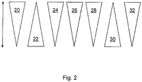
- the first triangle represents the frequency 20 of received signals. With increasing frequency 20 of the detection of received signals, the detection security measure 22 is correspondingly reduced and vice versa.
- the predetermined number 24 of successive scanning cycles for determining whether a detected object satisfies an object detection criterion is set to a low value. If the detection confidence measure 22 is reduced, this predetermined number 24 is increased by scanning cycles.
- This predetermined number 24 of scan cycles correlates with the response time 26 of the scanner 10, i. as the number 24 of consecutive scan cycles increases, so does the response time 26 and vice versa.
- the range 32 of the scanner 10 decreases (for a given desired absolute object resolution) with decreasing angular resolution 28 or increasing angular separation 30.
- Fig. 2 should only qualitatively illustrate the relationships between the different sizes and parameters. A quantitative relationship between the respective values is achieved by Fig. 2 not represented.
Applications Claiming Priority (1)
| Application Number | Priority Date | Filing Date | Title |
|---|---|---|---|
| DE102016115201.3A DE102016115201A1 (de) | 2016-08-16 | 2016-08-16 | Verfahren zum Betreiben eines Überwachungssensors und Überwachungssensor |
Publications (2)
| Publication Number | Publication Date |
|---|---|
| EP3287809A1 true EP3287809A1 (fr) | 2018-02-28 |
| EP3287809B1 EP3287809B1 (fr) | 2019-10-02 |
Family
ID=59569195
Family Applications (1)
| Application Number | Title | Priority Date | Filing Date |
|---|---|---|---|
| EP17185293.2A Active EP3287809B1 (fr) | 2016-08-16 | 2017-08-08 | Procédé de fonctionnement d'un dispositif de baleyage et dispositif de baleyage |
Country Status (3)
| Country | Link |
|---|---|
| US (1) | US10877132B2 (fr) |
| EP (1) | EP3287809B1 (fr) |
| DE (1) | DE102016115201A1 (fr) |
Cited By (1)
| Publication number | Priority date | Publication date | Assignee | Title |
|---|---|---|---|---|
| EP3588139A1 (fr) | 2018-06-26 | 2020-01-01 | Sick AG | Capteur optoélectronique et procédé de détermination de la distance |
Families Citing this family (2)
| Publication number | Priority date | Publication date | Assignee | Title |
|---|---|---|---|---|
| JP7059054B2 (ja) * | 2018-03-13 | 2022-04-25 | キヤノン株式会社 | 画像処理装置、画像処理方法およびプログラム |
| EP3889639A4 (fr) * | 2018-11-30 | 2022-01-05 | Koito Manufacturing Co., Ltd. | Capteur de télémétrie, feu de véhicule et procédé de télémétrie |
Citations (3)
| Publication number | Priority date | Publication date | Assignee | Title |
|---|---|---|---|---|
| EP1391752A2 (fr) * | 2002-08-21 | 2004-02-25 | Leuze lumiflex GmbH + Co. KG | Grille de lumière |
| EP2735887A1 (fr) * | 2012-11-22 | 2014-05-28 | Sick Ag | Dispositif d'enregistrement optique |
| EP2824478A1 (fr) * | 2013-07-11 | 2015-01-14 | Sick Ag | Capteur optoélectronique et procédé destiné à la détection d'objets et à la détermination de distance dans une zone de surveillance |
Family Cites Families (7)
| Publication number | Priority date | Publication date | Assignee | Title |
|---|---|---|---|---|
| DE10149768A1 (de) | 2001-10-09 | 2003-04-17 | Ibeo Automobile Sensor Gmbh | Sichtweitenbestimmung |
| DE10237761A1 (de) | 2002-08-17 | 2004-03-04 | Stn Atlas Elektronik Gmbh | Verfahren zur Schätzung der Antennengeometrie einer akustischen Linearantenne |
| JP4541101B2 (ja) * | 2004-10-21 | 2010-09-08 | アルパイン株式会社 | 他車両検出機および他車両検出方法 |
| DE202008016093U1 (de) | 2008-12-05 | 2010-04-15 | Sick Ag | Überwachungssensor |
| DE102010005993B4 (de) * | 2010-01-27 | 2016-10-20 | Deutsches Zentrum für Luft- und Raumfahrt e.V. | Laserscanner-Einrichtung und Verfahren zur dreidimensionalen berührungslosen Umgebungserfassung mit einer Laserscanner-Einrichtung |
| EP2703837B1 (fr) | 2012-09-03 | 2014-07-16 | Sick Ag | Scanner laser de sécurité |
| DE102012112987B3 (de) | 2012-12-21 | 2013-12-05 | Sick Ag | Optoelektronischer Sensor und Verfahren zur Erfassung und Abstandsbestimmung von Objekten |
-
2016
- 2016-08-16 DE DE102016115201.3A patent/DE102016115201A1/de not_active Ceased
-
2017
- 2017-08-08 EP EP17185293.2A patent/EP3287809B1/fr active Active
- 2017-08-14 US US15/676,715 patent/US10877132B2/en active Active
Patent Citations (3)
| Publication number | Priority date | Publication date | Assignee | Title |
|---|---|---|---|---|
| EP1391752A2 (fr) * | 2002-08-21 | 2004-02-25 | Leuze lumiflex GmbH + Co. KG | Grille de lumière |
| EP2735887A1 (fr) * | 2012-11-22 | 2014-05-28 | Sick Ag | Dispositif d'enregistrement optique |
| EP2824478A1 (fr) * | 2013-07-11 | 2015-01-14 | Sick Ag | Capteur optoélectronique et procédé destiné à la détection d'objets et à la détermination de distance dans une zone de surveillance |
Cited By (1)
| Publication number | Priority date | Publication date | Assignee | Title |
|---|---|---|---|---|
| EP3588139A1 (fr) | 2018-06-26 | 2020-01-01 | Sick AG | Capteur optoélectronique et procédé de détermination de la distance |
Also Published As
| Publication number | Publication date |
|---|---|
| US10877132B2 (en) | 2020-12-29 |
| US20180052225A1 (en) | 2018-02-22 |
| DE102016115201A1 (de) | 2018-02-22 |
| EP3287809B1 (fr) | 2019-10-02 |
Similar Documents
| Publication | Publication Date | Title |
|---|---|---|
| EP2824478B1 (fr) | Capteur optoélectronique et procédé destiné à la détection d'objets et à la détermination de distance dans une zone de surveillance | |
| EP2541273B1 (fr) | Détection et détermination de distance d'objets | |
| EP1788467B1 (fr) | Dispositif de protection | |
| EP2917756B1 (fr) | Dispositif de détection optoélectronique à balayage à seuil de détection, véhicule automobile et procédé afférent | |
| DE102012112987B3 (de) | Optoelektronischer Sensor und Verfahren zur Erfassung und Abstandsbestimmung von Objekten | |
| EP3330740B1 (fr) | Procédé de détection d'objets dans une zone de détection | |
| EP3435117B1 (fr) | Capteur et procédé de détection et de détermination des distances entre des objets | |
| EP3220164B1 (fr) | Procédé de fonctionnement d'un capteur écartométrique de surveillance et capteur écartométrique de surveillance | |
| DE102016114995A1 (de) | Vorrichtung und Verfahren zur Aufnahme von Entfernungsbildern | |
| EP3287809B1 (fr) | Procédé de fonctionnement d'un dispositif de baleyage et dispositif de baleyage | |
| EP0967492B2 (fr) | Méthode pour surveillance opto-électronique de zone de garde | |
| EP2306217B1 (fr) | Détermination d'un environnement | |
| DE10313194B4 (de) | Optoelektronische Vorrichtung und Verfahren zur Erfassung von Objekten mittels eines optischen Sensors | |
| EP2703837B1 (fr) | Scanner laser de sécurité | |
| EP3588139B1 (fr) | Capteur optoélectronique et procédé de détermination de la distance | |
| EP3587894A1 (fr) | Agencement de capteurs et procédé de fonctionnement d'un agencement de capteurs | |
| EP3026459B1 (fr) | Systeme de capteur | |
| EP3665505B1 (fr) | Détermination de la portée maximale d'un capteur lidar | |
| WO2019101506A1 (fr) | Procédé de fonctionnement d'un capteur lidar et capteur lidar | |
| DE202014105727U1 (de) | Sensorsystem | |
| DE202012105044U1 (de) | Optoelektronischer Sensor zur Erfassung und Abstandsbestimmung von Objekten | |
| DE102004032048A1 (de) | Verfahren und Vorrichtung zur Bestimmung der Ausrichtung eines ersten Objektes zu einem zweiten Objekt | |
| EP3715905B1 (fr) | Procédé de fonctionnement d'un capteur de surveillance de mesure de distance et capteur de surveillance de mesure de distance | |
| DE102004037859A1 (de) | Gerät und Verfahren zur Kollisionvermeidung | |
| DE102018126497A1 (de) | Verfahren zur Überprüfung einer Reichweite einer optischen Detektionsvorrichtung und optische Detektionsvorrichtung |
Legal Events
| Date | Code | Title | Description |
|---|---|---|---|
| PUAI | Public reference made under article 153(3) epc to a published international application that has entered the european phase |
Free format text: ORIGINAL CODE: 0009012 |
|
| STAA | Information on the status of an ep patent application or granted ep patent |
Free format text: STATUS: THE APPLICATION HAS BEEN PUBLISHED |
|
| AK | Designated contracting states |
Kind code of ref document: A1 Designated state(s): AL AT BE BG CH CY CZ DE DK EE ES FI FR GB GR HR HU IE IS IT LI LT LU LV MC MK MT NL NO PL PT RO RS SE SI SK SM TR |
|
| AX | Request for extension of the european patent |
Extension state: BA ME |
|
| STAA | Information on the status of an ep patent application or granted ep patent |
Free format text: STATUS: REQUEST FOR EXAMINATION WAS MADE |
|
| 17P | Request for examination filed |
Effective date: 20180625 |
|
| RBV | Designated contracting states (corrected) |
Designated state(s): AL AT BE BG CH CY CZ DE DK EE ES FI FR GB GR HR HU IE IS IT LI LT LU LV MC MK MT NL NO PL PT RO RS SE SI SK SM TR |
|
| STAA | Information on the status of an ep patent application or granted ep patent |
Free format text: STATUS: EXAMINATION IS IN PROGRESS |
|
| 17Q | First examination report despatched |
Effective date: 20181022 |
|
| GRAP | Despatch of communication of intention to grant a patent |
Free format text: ORIGINAL CODE: EPIDOSNIGR1 |
|
| STAA | Information on the status of an ep patent application or granted ep patent |
Free format text: STATUS: GRANT OF PATENT IS INTENDED |
|
| INTG | Intention to grant announced |
Effective date: 20190429 |
|
| GRAS | Grant fee paid |
Free format text: ORIGINAL CODE: EPIDOSNIGR3 |
|
| GRAA | (expected) grant |
Free format text: ORIGINAL CODE: 0009210 |
|
| STAA | Information on the status of an ep patent application or granted ep patent |
Free format text: STATUS: THE PATENT HAS BEEN GRANTED |
|
| AK | Designated contracting states |
Kind code of ref document: B1 Designated state(s): AL AT BE BG CH CY CZ DE DK EE ES FI FR GB GR HR HU IE IS IT LI LT LU LV MC MK MT NL NO PL PT RO RS SE SI SK SM TR |
|
| REG | Reference to a national code |
Ref country code: GB Ref legal event code: FG4D Free format text: NOT ENGLISH |
|
| REG | Reference to a national code |
Ref country code: CH Ref legal event code: EP Ref country code: AT Ref legal event code: REF Ref document number: 1186812 Country of ref document: AT Kind code of ref document: T Effective date: 20191015 |
|
| REG | Reference to a national code |
Ref country code: DE Ref legal event code: R096 Ref document number: 502017002442 Country of ref document: DE |
|
| REG | Reference to a national code |
Ref country code: IE Ref legal event code: FG4D Free format text: LANGUAGE OF EP DOCUMENT: GERMAN |
|
| REG | Reference to a national code |
Ref country code: NL Ref legal event code: MP Effective date: 20191002 |
|
| RAP2 | Party data changed (patent owner data changed or rights of a patent transferred) |
Owner name: SICK AG |
|
| REG | Reference to a national code |
Ref country code: LT Ref legal event code: MG4D |
|
| PG25 | Lapsed in a contracting state [announced via postgrant information from national office to epo] |
Ref country code: ES Free format text: LAPSE BECAUSE OF FAILURE TO SUBMIT A TRANSLATION OF THE DESCRIPTION OR TO PAY THE FEE WITHIN THE PRESCRIBED TIME-LIMIT Effective date: 20191002 Ref country code: NL Free format text: LAPSE BECAUSE OF FAILURE TO SUBMIT A TRANSLATION OF THE DESCRIPTION OR TO PAY THE FEE WITHIN THE PRESCRIBED TIME-LIMIT Effective date: 20191002 Ref country code: GR Free format text: LAPSE BECAUSE OF FAILURE TO SUBMIT A TRANSLATION OF THE DESCRIPTION OR TO PAY THE FEE WITHIN THE PRESCRIBED TIME-LIMIT Effective date: 20200103 Ref country code: FI Free format text: LAPSE BECAUSE OF FAILURE TO SUBMIT A TRANSLATION OF THE DESCRIPTION OR TO PAY THE FEE WITHIN THE PRESCRIBED TIME-LIMIT Effective date: 20191002 Ref country code: NO Free format text: LAPSE BECAUSE OF FAILURE TO SUBMIT A TRANSLATION OF THE DESCRIPTION OR TO PAY THE FEE WITHIN THE PRESCRIBED TIME-LIMIT Effective date: 20200102 Ref country code: BG Free format text: LAPSE BECAUSE OF FAILURE TO SUBMIT A TRANSLATION OF THE DESCRIPTION OR TO PAY THE FEE WITHIN THE PRESCRIBED TIME-LIMIT Effective date: 20200102 Ref country code: LT Free format text: LAPSE BECAUSE OF FAILURE TO SUBMIT A TRANSLATION OF THE DESCRIPTION OR TO PAY THE FEE WITHIN THE PRESCRIBED TIME-LIMIT Effective date: 20191002 Ref country code: PL Free format text: LAPSE BECAUSE OF FAILURE TO SUBMIT A TRANSLATION OF THE DESCRIPTION OR TO PAY THE FEE WITHIN THE PRESCRIBED TIME-LIMIT Effective date: 20191002 Ref country code: PT Free format text: LAPSE BECAUSE OF FAILURE TO SUBMIT A TRANSLATION OF THE DESCRIPTION OR TO PAY THE FEE WITHIN THE PRESCRIBED TIME-LIMIT Effective date: 20200203 Ref country code: LV Free format text: LAPSE BECAUSE OF FAILURE TO SUBMIT A TRANSLATION OF THE DESCRIPTION OR TO PAY THE FEE WITHIN THE PRESCRIBED TIME-LIMIT Effective date: 20191002 Ref country code: SE Free format text: LAPSE BECAUSE OF FAILURE TO SUBMIT A TRANSLATION OF THE DESCRIPTION OR TO PAY THE FEE WITHIN THE PRESCRIBED TIME-LIMIT Effective date: 20191002 |
|
| PG25 | Lapsed in a contracting state [announced via postgrant information from national office to epo] |
Ref country code: HR Free format text: LAPSE BECAUSE OF FAILURE TO SUBMIT A TRANSLATION OF THE DESCRIPTION OR TO PAY THE FEE WITHIN THE PRESCRIBED TIME-LIMIT Effective date: 20191002 Ref country code: RS Free format text: LAPSE BECAUSE OF FAILURE TO SUBMIT A TRANSLATION OF THE DESCRIPTION OR TO PAY THE FEE WITHIN THE PRESCRIBED TIME-LIMIT Effective date: 20191002 Ref country code: IS Free format text: LAPSE BECAUSE OF FAILURE TO SUBMIT A TRANSLATION OF THE DESCRIPTION OR TO PAY THE FEE WITHIN THE PRESCRIBED TIME-LIMIT Effective date: 20200224 Ref country code: CZ Free format text: LAPSE BECAUSE OF FAILURE TO SUBMIT A TRANSLATION OF THE DESCRIPTION OR TO PAY THE FEE WITHIN THE PRESCRIBED TIME-LIMIT Effective date: 20191002 |
|
| PG25 | Lapsed in a contracting state [announced via postgrant information from national office to epo] |
Ref country code: AL Free format text: LAPSE BECAUSE OF FAILURE TO SUBMIT A TRANSLATION OF THE DESCRIPTION OR TO PAY THE FEE WITHIN THE PRESCRIBED TIME-LIMIT Effective date: 20191002 |
|
| REG | Reference to a national code |
Ref country code: DE Ref legal event code: R097 Ref document number: 502017002442 Country of ref document: DE |
|
| PG2D | Information on lapse in contracting state deleted |
Ref country code: IS |
|
| PG25 | Lapsed in a contracting state [announced via postgrant information from national office to epo] |
Ref country code: RO Free format text: LAPSE BECAUSE OF FAILURE TO SUBMIT A TRANSLATION OF THE DESCRIPTION OR TO PAY THE FEE WITHIN THE PRESCRIBED TIME-LIMIT Effective date: 20191002 Ref country code: DK Free format text: LAPSE BECAUSE OF FAILURE TO SUBMIT A TRANSLATION OF THE DESCRIPTION OR TO PAY THE FEE WITHIN THE PRESCRIBED TIME-LIMIT Effective date: 20191002 Ref country code: EE Free format text: LAPSE BECAUSE OF FAILURE TO SUBMIT A TRANSLATION OF THE DESCRIPTION OR TO PAY THE FEE WITHIN THE PRESCRIBED TIME-LIMIT Effective date: 20191002 Ref country code: IS Free format text: LAPSE BECAUSE OF FAILURE TO SUBMIT A TRANSLATION OF THE DESCRIPTION OR TO PAY THE FEE WITHIN THE PRESCRIBED TIME-LIMIT Effective date: 20200202 |
|
| PLBE | No opposition filed within time limit |
Free format text: ORIGINAL CODE: 0009261 |
|
| STAA | Information on the status of an ep patent application or granted ep patent |
Free format text: STATUS: NO OPPOSITION FILED WITHIN TIME LIMIT |
|
| PG25 | Lapsed in a contracting state [announced via postgrant information from national office to epo] |
Ref country code: SM Free format text: LAPSE BECAUSE OF FAILURE TO SUBMIT A TRANSLATION OF THE DESCRIPTION OR TO PAY THE FEE WITHIN THE PRESCRIBED TIME-LIMIT Effective date: 20191002 Ref country code: SK Free format text: LAPSE BECAUSE OF FAILURE TO SUBMIT A TRANSLATION OF THE DESCRIPTION OR TO PAY THE FEE WITHIN THE PRESCRIBED TIME-LIMIT Effective date: 20191002 |
|
| 26N | No opposition filed |
Effective date: 20200703 |
|
| PG25 | Lapsed in a contracting state [announced via postgrant information from national office to epo] |
Ref country code: SI Free format text: LAPSE BECAUSE OF FAILURE TO SUBMIT A TRANSLATION OF THE DESCRIPTION OR TO PAY THE FEE WITHIN THE PRESCRIBED TIME-LIMIT Effective date: 20191002 |
|
| PG25 | Lapsed in a contracting state [announced via postgrant information from national office to epo] |
Ref country code: MC Free format text: LAPSE BECAUSE OF FAILURE TO SUBMIT A TRANSLATION OF THE DESCRIPTION OR TO PAY THE FEE WITHIN THE PRESCRIBED TIME-LIMIT Effective date: 20191002 |
|
| REG | Reference to a national code |
Ref country code: CH Ref legal event code: PL |
|
| PG25 | Lapsed in a contracting state [announced via postgrant information from national office to epo] |
Ref country code: LU Free format text: LAPSE BECAUSE OF NON-PAYMENT OF DUE FEES Effective date: 20200808 Ref country code: LI Free format text: LAPSE BECAUSE OF NON-PAYMENT OF DUE FEES Effective date: 20200831 Ref country code: CH Free format text: LAPSE BECAUSE OF NON-PAYMENT OF DUE FEES Effective date: 20200831 |
|
| REG | Reference to a national code |
Ref country code: BE Ref legal event code: MM Effective date: 20200831 |
|
| PG25 | Lapsed in a contracting state [announced via postgrant information from national office to epo] |
Ref country code: FR Free format text: LAPSE BECAUSE OF NON-PAYMENT OF DUE FEES Effective date: 20200831 |
|
| PG25 | Lapsed in a contracting state [announced via postgrant information from national office to epo] |
Ref country code: BE Free format text: LAPSE BECAUSE OF NON-PAYMENT OF DUE FEES Effective date: 20200831 Ref country code: IE Free format text: LAPSE BECAUSE OF NON-PAYMENT OF DUE FEES Effective date: 20200808 |
|
| GBPC | Gb: european patent ceased through non-payment of renewal fee |
Effective date: 20210808 |
|
| PG25 | Lapsed in a contracting state [announced via postgrant information from national office to epo] |
Ref country code: TR Free format text: LAPSE BECAUSE OF FAILURE TO SUBMIT A TRANSLATION OF THE DESCRIPTION OR TO PAY THE FEE WITHIN THE PRESCRIBED TIME-LIMIT Effective date: 20191002 Ref country code: MT Free format text: LAPSE BECAUSE OF FAILURE TO SUBMIT A TRANSLATION OF THE DESCRIPTION OR TO PAY THE FEE WITHIN THE PRESCRIBED TIME-LIMIT Effective date: 20191002 Ref country code: CY Free format text: LAPSE BECAUSE OF FAILURE TO SUBMIT A TRANSLATION OF THE DESCRIPTION OR TO PAY THE FEE WITHIN THE PRESCRIBED TIME-LIMIT Effective date: 20191002 |
|
| PG25 | Lapsed in a contracting state [announced via postgrant information from national office to epo] |
Ref country code: MK Free format text: LAPSE BECAUSE OF FAILURE TO SUBMIT A TRANSLATION OF THE DESCRIPTION OR TO PAY THE FEE WITHIN THE PRESCRIBED TIME-LIMIT Effective date: 20191002 |
|
| PG25 | Lapsed in a contracting state [announced via postgrant information from national office to epo] |
Ref country code: GB Free format text: LAPSE BECAUSE OF NON-PAYMENT OF DUE FEES Effective date: 20210808 |
|
| REG | Reference to a national code |
Ref country code: AT Ref legal event code: MM01 Ref document number: 1186812 Country of ref document: AT Kind code of ref document: T Effective date: 20220808 |
|
| PG25 | Lapsed in a contracting state [announced via postgrant information from national office to epo] |
Ref country code: AT Free format text: LAPSE BECAUSE OF NON-PAYMENT OF DUE FEES Effective date: 20220808 |
|
| PGFP | Annual fee paid to national office [announced via postgrant information from national office to epo] |
Ref country code: IT Payment date: 20230831 Year of fee payment: 7 |
|
| PGFP | Annual fee paid to national office [announced via postgrant information from national office to epo] |
Ref country code: DE Payment date: 20230822 Year of fee payment: 7 |