EP3287809A1 - Method for operating a scanner and scanner - Google Patents
Method for operating a scanner and scanner Download PDFInfo
- Publication number
- EP3287809A1 EP3287809A1 EP17185293.2A EP17185293A EP3287809A1 EP 3287809 A1 EP3287809 A1 EP 3287809A1 EP 17185293 A EP17185293 A EP 17185293A EP 3287809 A1 EP3287809 A1 EP 3287809A1
- Authority
- EP
- European Patent Office
- Prior art keywords
- scanner
- light
- monitoring
- detection
- frequency
- Prior art date
- Legal status (The legal status is an assumption and is not a legal conclusion. Google has not performed a legal analysis and makes no representation as to the accuracy of the status listed.)
- Granted
Links
- 238000000034 method Methods 0.000 title claims abstract description 28
- 238000001514 detection method Methods 0.000 claims abstract description 89
- 238000012544 monitoring process Methods 0.000 claims abstract description 59
- 230000001681 protective effect Effects 0.000 claims abstract description 43
- 230000002829 reductive effect Effects 0.000 claims abstract description 21
- 238000005070 sampling Methods 0.000 claims abstract description 21
- 230000003247 decreasing effect Effects 0.000 claims abstract description 12
- 238000011156 evaluation Methods 0.000 claims description 25
- 230000007423 decrease Effects 0.000 claims description 11
- 230000008859 change Effects 0.000 claims description 8
- 230000004044 response Effects 0.000 description 25
- 230000007613 environmental effect Effects 0.000 description 15
- 239000002245 particle Substances 0.000 description 9
- 230000000875 corresponding effect Effects 0.000 description 8
- 241000533950 Leucojum Species 0.000 description 4
- 230000002411 adverse Effects 0.000 description 4
- 230000000007 visual effect Effects 0.000 description 4
- 230000001419 dependent effect Effects 0.000 description 3
- 239000000428 dust Substances 0.000 description 3
- 230000002452 interceptive effect Effects 0.000 description 3
- 230000009467 reduction Effects 0.000 description 3
- 241000238631 Hexapoda Species 0.000 description 2
- 230000009471 action Effects 0.000 description 2
- 230000005540 biological transmission Effects 0.000 description 2
- 230000002596 correlated effect Effects 0.000 description 2
- 239000000463 material Substances 0.000 description 2
- 230000008569 process Effects 0.000 description 2
- 238000000926 separation method Methods 0.000 description 2
- 241001136792 Alle Species 0.000 description 1
- 238000009825 accumulation Methods 0.000 description 1
- 230000000052 comparative effect Effects 0.000 description 1
- 238000007796 conventional method Methods 0.000 description 1
- 230000006735 deficit Effects 0.000 description 1
- 238000013461 design Methods 0.000 description 1
- 230000002349 favourable effect Effects 0.000 description 1
- 230000004313 glare Effects 0.000 description 1
- 238000005259 measurement Methods 0.000 description 1
- 238000012986 modification Methods 0.000 description 1
- 230000004048 modification Effects 0.000 description 1
- 230000005693 optoelectronics Effects 0.000 description 1
- 230000010363 phase shift Effects 0.000 description 1
- 238000012545 processing Methods 0.000 description 1
- 230000005855 radiation Effects 0.000 description 1
- 238000004904 shortening Methods 0.000 description 1
- 230000011664 signaling Effects 0.000 description 1
- 230000001960 triggered effect Effects 0.000 description 1
Images

Classifications
-
- G—PHYSICS
- G01—MEASURING; TESTING
- G01S—RADIO DIRECTION-FINDING; RADIO NAVIGATION; DETERMINING DISTANCE OR VELOCITY BY USE OF RADIO WAVES; LOCATING OR PRESENCE-DETECTING BY USE OF THE REFLECTION OR RERADIATION OF RADIO WAVES; ANALOGOUS ARRANGEMENTS USING OTHER WAVES
- G01S7/00—Details of systems according to groups G01S13/00, G01S15/00, G01S17/00
- G01S7/48—Details of systems according to groups G01S13/00, G01S15/00, G01S17/00 of systems according to group G01S17/00
- G01S7/481—Constructional features, e.g. arrangements of optical elements
- G01S7/4817—Constructional features, e.g. arrangements of optical elements relating to scanning
-
- G—PHYSICS
- G01—MEASURING; TESTING
- G01S—RADIO DIRECTION-FINDING; RADIO NAVIGATION; DETERMINING DISTANCE OR VELOCITY BY USE OF RADIO WAVES; LOCATING OR PRESENCE-DETECTING BY USE OF THE REFLECTION OR RERADIATION OF RADIO WAVES; ANALOGOUS ARRANGEMENTS USING OTHER WAVES
- G01S17/00—Systems using the reflection or reradiation of electromagnetic waves other than radio waves, e.g. lidar systems
- G01S17/02—Systems using the reflection of electromagnetic waves other than radio waves
- G01S17/06—Systems determining position data of a target
- G01S17/42—Simultaneous measurement of distance and other co-ordinates
-
- G—PHYSICS
- G01—MEASURING; TESTING
- G01S—RADIO DIRECTION-FINDING; RADIO NAVIGATION; DETERMINING DISTANCE OR VELOCITY BY USE OF RADIO WAVES; LOCATING OR PRESENCE-DETECTING BY USE OF THE REFLECTION OR RERADIATION OF RADIO WAVES; ANALOGOUS ARRANGEMENTS USING OTHER WAVES
- G01S7/00—Details of systems according to groups G01S13/00, G01S15/00, G01S17/00
- G01S7/48—Details of systems according to groups G01S13/00, G01S15/00, G01S17/00 of systems according to group G01S17/00
- G01S7/483—Details of pulse systems
- G01S7/486—Receivers
- G01S7/4861—Circuits for detection, sampling, integration or read-out
-
- G—PHYSICS
- G01—MEASURING; TESTING
- G01S—RADIO DIRECTION-FINDING; RADIO NAVIGATION; DETERMINING DISTANCE OR VELOCITY BY USE OF RADIO WAVES; LOCATING OR PRESENCE-DETECTING BY USE OF THE REFLECTION OR RERADIATION OF RADIO WAVES; ANALOGOUS ARRANGEMENTS USING OTHER WAVES
- G01S17/00—Systems using the reflection or reradiation of electromagnetic waves other than radio waves, e.g. lidar systems
- G01S17/88—Lidar systems specially adapted for specific applications
- G01S17/93—Lidar systems specially adapted for specific applications for anti-collision purposes
- G01S17/931—Lidar systems specially adapted for specific applications for anti-collision purposes of land vehicles
Definitions
- the present invention relates to a method for operating a scanner for monitoring an at least two-dimensional protective field, which is subdivided into a plurality of cyclically scannable monitoring fields, wherein the scanner comprises at least one light transmitter and at least one light receiver.
- Such a scanner can be designed for example as a laser scanner.
- One of a light emitter, e.g. A laser or the like, generated transmitted light beam is directed via a light deflection unit in the protective field to be monitored and there reflected or remitted by an optionally present object.
- the reflected or remitted light passes back to the scanner and is detected there by the light receiver.
- the light deflecting unit is pivotable or rotatable, so that the light beam generated by the light emitter sweeps over a protective field corresponding to the pivoting or rotational movement. If a received by the light receiver reflected light signal received from the protection area, it can be concluded from the angular position of the deflection on the angular position of the object in the protective field.
- the scanner when it detects an invalid object in the protective field, it may output a corresponding object detection signal.
- Such scanners are used, for example, in mobile or stationary machines or vehicles, in which, for safety reasons, a danger zone must be monitored, which must not be injured by persons or objects during operation of the machine or of the vehicle.
- a danger zone must be monitored, which must not be injured by persons or objects during operation of the machine or of the vehicle.
- a shutdown of the machine, a stop of the vehicle or the like may be effected on the basis of the object detection signal.
- the concept of so-called multiple evaluation can be applied.
- This concept envisages considering two or more consecutive sampling cycles, and in each of these sampling cycles an object must be detected at the same location or within a defined environment in order to trigger an object detection signal. It is assumed that such objects which could trigger a false positive object detection signal move relatively quickly and therefore are detected only in a part of the considered sampling cycles and / or in all sampling cycles but at very far apart positions.
- the robustness of the sensor is increased against disturbances that are based on small occluding objects or particles such as insects, raindrops, shavings or snowflakes, so that increases the availability of monitored by the sensor machine.
- the number of sampling cycles to be evaluated also increases the response time of the sensor, as a multiple sampling requires more time accordingly.
- an increased response time may, for example, make it necessary to reduce the operating speed of the monitored machine because, for example, it must be ensured that a safe stop has taken place before the object (eg, an endangered person) has approached the machine or itself the machine (for example a driverless transport system) has approached an endangered person.
- Another way to counter this is to increase the monitored protective field. This would detect the object earlier (for example, an endangered person), but the probability of false shutdown increases as more area is monitored.
- EP 2 703 837 B1 a safety laser scanner is described in which light pulses of two different wavelengths are emitted offset in time and evaluated accordingly to compensate for visual hazards that can be caused by fog, rain, snow or dust.
- DE 101 49 768 A1 Proposes a laser scanner in which a disturbance impairing the visibility is detected on the basis of characteristic disturbance characteristics that can be identified by means of a sensor by evaluating the reflected radiation.
- a monitoring field is understood to mean, in particular, a spatial region into which a transmitted light beam is emitted, in which case the transmitted light beams can be emitted in particular pulsed.
- a monitoring field can also be regarded as a spatial area in which the light receiver "looks" at a respective sampling time or at a respective sampling position, in particular scanning angle position, and optionally for an associated sampling period, ie Light receiver is activated and / or evaluated.
- the frequency corresponds, for example, to a number of received signals normalized with respect to the sampled range. As a rule, this number is directly correlated with the number of received signals per unit of time. A simple possibility provides that the frequency is determined by the number of received signals generated per unit of time.
- the frequency can usually be determined globally for all monitoring fields of the protective field. However, it is also possible to determine a specific frequency individually for each monitoring field or for groups with several monitoring fields each.
- the aforementioned detection confidence measure thus represents a quantifying measure of the environmental conditions under which the scanner is operated. If disturbing objects, which can contribute to the triggering of false-positive object detection signals, are not present at all or only in a very small number, as a rule only very few receive signals are generated per unit of time.
- This signals to the scanner that the environmental conditions under which the scanner is operated are uncritical and, for example, rules according to which the scanner outputs output signals to a signal output from the scanner, can be chosen or specified differently than in the presence of critical environmental conditions in which relatively frequently disturbing particles such as insects, raindrops, chips of material or snowflakes penetrate into the protective field and lead to an increased frequency of received signals.
- the detection confidence measure may include both discrete values, which may for example be determined on the basis of one or more thresholds for the determined frequency, or also continuous or quasi-continuous, e.g. assume values that are conditional on digitization.
- a first signal can be output at a signal output of the scanner on the basis of the detection security measure.
- This signal output can, for example, be connected to a machine or a vehicle to be monitored by the scanner and trigger certain measures in this machine or this vehicle.
- the machine or vehicle may be signaled that the operating speed of the vehicle or a vehicle speed must be reduced, or that generally, the operation must be in a safer mode .
- This signaling may in particular include that the machine or the vehicle is informed that the response time of the scanner has increased due to changes in the operating conditions of the scanner, which will be explained in more detail below.
- Said first signal may assume a continuous or quasi-continuous value or be configured as a discrete single-stage or multi-stage switching signal if the detection safety measure has undershot or exceeded one or more predetermined threshold values.
- the detection security measure can be forwarded to the signal output for further processing.
- the resulting response time can be determined from the detection confidence measure and output to set the maximum operating speed or driving speed.
- the signal output at the signal output may cause an autonomously traveling industrial vehicle to operate at a reduced travel speed, for example, when snowfall in the operating environment of the scanner leads to an increase in the frequency at which received signals are generated, thereby lowering the detection confidence level.
- the driving speed can be increased again when the snow decreases or stops and thus the frequency of the received signals decreases and the detection safety measure increases again.
- the predetermined multiple evaluation number it can be determined on the basis of the received signals generated over a predetermined number of successive sampling cycles (hereinafter also “multiple evaluation number") whether a detected object fulfills at least one predetermined object detection criterion for an invalid object and generates an object detection signal when the object detection criterion is met, wherein the predetermined multiple evaluation number is determined based at least on the detection confidence measure.
- the mentioned object detection signal can be output, for example as an alternative or in addition to the said first signal as a second signal at a (further) signal output of the scanner and can trigger certain measures on a machine connected to the scanner or a vehicle, in particular in comparison with the said first signal triggered measures can be further and, for example, may consist in that the machine is switched off or the vehicle is braked to a standstill.
- the value of the detection confidence measure may directly represent the predetermined multiple evaluation number.
- the reception signals generated during each cycle may be stored for the predetermined multiple evaluation number, and the object detection signal may be generated based on the stored reception signals.
- the above-mentioned predetermined object detection criterion can be, for example, that a received signal which signals the presence of an object in one or more mutually adjacent monitoring fields in several, namely the predetermined number of successive sampling cycles (multiple evaluation number) in the same or the same monitoring fields a defined environment of this or these monitoring fields must occur, so that an object detection signal is generated.
- the scanner may be operated with a minimum number, for example 1, of consecutive scan cycles when a high degree of detection confidence dictates the presence of favorable environmental conditions, i. without interfering particles, signaled. Since safety-critical objects can be detected within one sampling cycle, the response time of the scanner in this mode is very short.
- the amount of detection confidence decreases and causes the predetermined multiple evaluation number to be increased, for example to 2, 3 or more.
- the robustness of the scanner or the availability of a connected machine or a connected vehicle can essentially be maintained, since the increased number of sampling cycles that are evaluated makes it possible to discriminate the interfering particles from actually safety-critical objects.
- the object detection criterion comprises determining, for the predetermined multiple evaluation number, that at least one detected object has a predefined minimum size and / or is in particular stationary in at least one of the monitoring fields.
- stationary objects or objects moving within a predetermined speed range or angular velocity range can fulfill the object detection criterion.
- an angle-stationary object which remains in the same angular position, but changes its distance from the scanner, which can not be detected, for example due to a lack of distance measurement.
- the predetermined multiple evaluation count is increased as the detection confidence level decreases and / or decreases the predetermined multiple evaluation count as the detection confidence measure increases.
- An increased response time which is due to an increased predetermined multiple evaluation number, and the associated security risks can be advantageously compensated by - as already mentioned above - a corresponding first signal is output to a signal output of the scanner, which leads, for example, that the Engine or the vehicle are operated at a reduced operating speed, so that the increased response time can be compensated by a reduced follow-up time of the machine to a stop or a reduced braking distance of the vehicle.
- the predetermined multiple count number can be reduced, thereby shortening the response time and allowing the machine or vehicle to operate at a higher or original speed.
- this response time can be communicated to a signal output so that it can be taken into account by a downstream controller.
- it may be displayed on a display unit, for example, to inform a user of the changed response time.
- Determining the frequency with which receive signals are generated and determining the detection confidence measure based on this frequency may include, for a predetermined time period, the number of registered ones Receiving signals is determined, and that the detection security measure is set to a predetermined value based on the determined number of registered received signals.
- the detection confidence measure can be set to a maximum value if no received signal was registered in the predetermined period.
- the detection security measure can be set to lower values, wherein the assignment of the values can be based, for example, on the basis of a lookup table or by means of a corresponding function.
- the said predetermined period of time does not necessarily have to be predefined, but can also be adapted dynamically, in particular in an iterative manner, to the respective number of registered received signals.
- the frequency can be normalized to a predetermined space area (that is, for example, an angle swept by the laser beam angle range), via which the number of registered received signals is determined.
- a respective received signal in addition to the information about the angular position of the monitoring field also include information about the distance of an object located therein from the scanner.
- the scanner may thus be a pure angle scanner or a distance-measuring scanner.
- the size of a detected object is determined by determining the size of an angular range over which the respective object extends on the basis of the number of adjacent monitoring fields in which the presence of an object has been detected at substantially the same distance from the scanner, and whose angular distances and the determined distance of the object from the scanner is determined.
- the determined distance in particular, it may be a mean distance determined from the distances of the respective monitoring fields.
- the method according to the invention serves to operate a scanner, in particular a laser scanner, preferably configured with a rotatable light deflection unit for deflecting the light of the light source into the protective field.
- the scanner is then designed to monitor one or more scanning surfaces, the monitoring fields being in particular sector-shaped.
- the monitoring fields can be sector-shaped both in two and in three dimensions.
- the magnitude of the angular resolution with which the protective field is scanned is adjustable as a function of the degree of detection reliability, wherein the angular resolution is reduced as the degree of detection confidence increases and / or the angular resolution is increased as the degree of detection reliability decreases , Said angular resolution is reciprocal to the angular distance of two adjacent monitoring fields, so that a small angular resolution corresponds to a large angular distance and vice versa.
- Changing the angle resolution usually only changes the size of the monitoring fields as well as the number of monitoring fields, since in most cases the size of the angular range over which the protective field extends should not be changed. Reducing the angular resolution reduces the number of samples per scan cycle and thus the duration of a scan cycle.
- the changed response time can be communicated to a signal output so that it can be taken into account by a downstream controller.
- it may be displayed on a display unit, for example, to inform a user of the changed response time.
- increasing and / or decreasing the value of the detection confidence measure takes place with a change in the frequency (with which received signals are determined) with a time delay.
- the time delay may be different for increasing and decreasing, respectively. For example, a slow response to decreased frequency and a fast response to increased frequency may occur.
- increasing and / or decreasing the predetermined number of consecutive sampling cycles can also be done with a time delay.
- those received signals which are not attributable to an object present in the protective field can also be taken into account for determining the degree of detection reliability.
- Such received signals may, for example, be due to detection of extraneous light by the light receiver, for example in the case of a "glare" of the scanner.
- the present invention further relates to a, in particular distance-measuring, scanner for monitoring an at least two-dimensional protective field, which is subdivided into a plurality of cyclically scannable monitoring fields, wherein the scanner comprises at least one light emitter, at least one light receiver and a control unit, and wherein the control unit for carrying out the method is designed according to one of the embodiments described above.
- Fig. 1 shows a scanner 10, for example, a distance-measuring laser scanner, which monitors a protective field 12 in the present example, which extends approximately over an angular range of 165 °.
- the scanner 10 has a light transmitter for emitting a transmitted light beam 16 into the protective field 12, a light receiver for receiving light which is reflected or remitted by an object 18 possibly present in the protective field, and a deflection unit which is designed to control the transmission angle. ie the angle at which the transmitted light beam 16 is transmitted with respect to the protective field 12, and optionally also the receiving angle, ie the angular direction from which light reflected or remitted relative to the protective field 12 is received, synchronously to the transmission angle. After a certain angle change can each one Emitted light pulse and optionally backscattered received light can be detected.
- Each light path 14 here is assigned a sector-shaped monitoring field which extends on both sides of the respective light path 14, since the transmitted light beam 16 does not propagate exactly along a line, as shown in the present schematic embodiment, but has a certain divergence.
- the design of the scanner 10 takes place in such a way that the monitoring fields assigned to the light paths 14 adjoin one another. However, adjacent monitoring fields may also overlap or be spaced apart to some extent. In the present example, 15 light paths 14 or monitoring fields are provided.
- the present invention is not limited to such a scanner, in which the individual light paths 14 are scanned in succession. It is also possible to scan all light paths 14 or groups of light paths 14 synchronously, which requires a corresponding number of light transmitter / receiver pairs. Further, the scanner 10 need not necessarily have only a single scan area, which in the present example is defined by the plane of the drawing, but may also have multiple scan areas, eg, multiple scan planes or more than one scan area or a plurality of tapered scan areas with different azimuth angles. If the scanner 10 is designed as a distance-measuring scanner, the determination of the distance to a detected object in a conventional manner due to the duration of the transmitted light beam 14 or the phase shift between modulated transmitted light and the received light.
- the scanner 10 may include an integrated control unit configured to generate receive signals based on the light received by the light receiver.
- the receive signals may include information about the angular position of this monitor field and about the distance of the object from the scanner 10, specifically for a monitor field in which light was scattered back from an object.
- the protective field is scanned cyclically, so that there is a time sequence of received signals for each light path 14 or each monitoring field.
- the scanner 10 may include a memory device which stores the received signals over one or more sampling cycles.
- the size of a detected object 18 may be determined based on the determined distance of the object 18 from the scanner 10 and the determined size of the angular range over which the detected object extends.
- the determination of the size of the angular range over which the object extends can be determined on the basis of the number of adjacent monitoring fields which are violated by the presence of the object and their angular distances.
- the angular resolution of the scanner 10 can be changed.
- An increase in the angular resolution corresponds to a reduction in the angular spacing between two adjacent light paths 14 or monitoring fields and vice versa. If the size of the protective field 12 should remain unchanged, the number of light paths 14 or the monitoring fields must be adjusted accordingly.
- the spacing of adjacent light paths 14 and monitoring fields, respectively increases for a given radial Distance from the scanner 10. Due to this, the range of the scanner 10 is limited depending on a minimum size for just yet to be detected objects.
- the distance between two adjacent transmitted light beams 14 must be smaller than the size of the object 18 for the reliable detection of an object 18 which is at a range corresponding to the range of the distance to the scanner 10. It is understood that with a reduction of the angular resolution this distance between adjacent transmitted light beams 14 increases and thus reduces the range of the scanner, assuming a constant minimum size for an object 18 to be detected.
- the control unit of the scanner 10 is designed to determine a frequency with which receive signals are generated and to determine a detection confidence measure on the basis of this frequency, the value of the detection confidence measure being increased with decreasing frequency and decreasing with increasing frequency.
- the frequency corresponds, for example, to a number of received signals normalized with respect to the sampled range. As a rule, this number is directly correlated with the number of received signals per unit of time.
- the frequency may be defined, for example, as the number of received signals per angular unit (the area swept by the laser beam). In a continuously operated at the same speed scanner thus results in the frequency as the number of received signals per unit time.
- the frequency can be determined globally for all monitoring fields (that is, the sum across all monitoring fields), but also specifically for each individual monitoring field or for a group of monitoring fields. Furthermore, it is possible to exclude certain received signals from the determination of the frequency, for example, if it is determined that the received signals are due to an object that is classified as safety-critical, for example due to its dimensions.
- the control unit may be configured to perform various actions based on the detection confidence measure.
- a first signal can be output at a signal output of the scanner 10.
- This signal can be output, for example, if the detection security measure falls below a predetermined threshold value.
- This first signal can be used, for example, to initiate a stop of the machine or of the vehicle or at least a reduction in the speed of movement of the machine or of the vehicle in the case of an engine or a vehicle monitored by the scanner 10.
- the detection confidence measure may be used to determine a predetermined number of consecutive sampling cycles (multiple evaluation number) for determining whether a detected object satisfies at least a predetermined object detection criterion for an invalid object, the control unit generating an object detection signal when the object detection criterion is met ,
- the object detection signal may alternatively or in addition to the first signal output as a second signal at an optionally further signal output of the scanner 10 and may be at a associated with the scanner 10 certain, in particular to trigger further action, such as an emergency shutdown.
- the object detection criterion may include determining that at least one detected object has a predefined minimum size and / or is located in particular stationary or within a predetermined speed range moving in at least one of the monitoring fields for the predetermined number of successive scanning cycles , By increasing this number of consecutive sampling cycles (multiple number of evaluations), it is possible to improve the robustness of the scanner 10 against such disturbances in adverse environmental conditions with relatively common interfering particles which are not intrinsically safety critical. Since an actual safety-critical object must thus be "observed” over several scanning cycles in order to distinguish it reliably from a non-safety-critical particle or small object, the response time of the scanner increases, ie. the time between the entry of a safety-critical object into the protective field and the output of an object detection signal which triggers corresponding safety measures in the case of a machine connected to the scanner 10.
- This increased response time can be compensated, for example, by operating the machine with increased safety measures, for example a reduced speed of movement or movement.
- the changed response time can be reported, for example, to a downstream controller or displayed to a user.
- the present invention makes it possible to dynamically adapt these increased safety measures, that is, depending on the environmental conditions. If the frequency of small particle disturbances decreases again and the environmental conditions improve, the previous one can help Increasing the predetermined multiple number of evaluations are withdrawn, so that the response time of the scanner is reduced again. Accordingly, the signal which triggers the corresponding safety precautions in the monitored machine, be withdrawn or at least reduced, so that the machine can be operated again with increased or maximum operating speed.
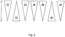
- the first triangle represents the frequency 20 of received signals. With increasing frequency 20 of the detection of received signals, the detection security measure 22 is correspondingly reduced and vice versa.
- the predetermined number 24 of successive scanning cycles for determining whether a detected object satisfies an object detection criterion is set to a low value. If the detection confidence measure 22 is reduced, this predetermined number 24 is increased by scanning cycles.
- This predetermined number 24 of scan cycles correlates with the response time 26 of the scanner 10, i. as the number 24 of consecutive scan cycles increases, so does the response time 26 and vice versa.
- the range 32 of the scanner 10 decreases (for a given desired absolute object resolution) with decreasing angular resolution 28 or increasing angular separation 30.
- Fig. 2 should only qualitatively illustrate the relationships between the different sizes and parameters. A quantitative relationship between the respective values is achieved by Fig. 2 not represented.
Abstract
Die vorliegende Erfindung betrifft ein Verfahren zum Betreiben eines Scanners zur Überwachung eines zumindest zweidimensionalen Schutzfeldes, welches in mehrere zyklisch abtastbare Überwachungsfelder unterteilt ist, wobei der Scanner zumindest einen Lichtsender und zumindest einen Lichtempfänger umfasst, mit den Schritten: - Aussenden von Sendelichtstrahlen in das Schutzfeld durch den Lichtsender, - Empfangen von Licht, welches von einem gegebenenfalls in dem Schutzfeld vorhandenen Objekt reflektiert oder remittiert wird, durch den Lichtempfänger, - Erzeugen eines Empfangssignals für das jeweilige Überwachungsfeld auf der Grundlage des empfangenen Lichts, wobei innerhalb eines Abtastzyklus alle Überwachungsfelder des Schutzfeldes einmal abgetastet werden, - Ermitteln einer Häufigkeit, mit welcher Empfangssignale erzeugt werden, und - Ermitteln eines Detektionssicherheitsmaßes zumindest auf der Grundlage der Häufigkeit, wobei der Wert des Detektionssicherheitsmaßes mit sinkender Häufigkeit erhöht wird und mit steigender Häufigkeit verringert wird. Die Erfindung betrifft ferner einen Scanner (10) zur Überwachung eines zumindest zweidimensionalen Schutzfeldes (12).The present invention relates to a method for operating a scanner for monitoring an at least two-dimensional protective field, which is subdivided into a plurality of cyclically scannable monitoring fields, wherein the scanner comprises at least one light transmitter and at least one light receiver, with the steps: Sending out transmitted light beams into the protective field by the light emitter, Receiving light, which is reflected or remitted by an object which may be present in the protective field, by the light receiver, Generating a received signal for the respective monitoring field on the basis of the received light, wherein all monitoring fields of the protective field are scanned once within one sampling cycle, Determining a frequency with which received signals are generated, and - Determining a detection security measure at least on the basis of the frequency, wherein the value of the detection security measure is increased with decreasing frequency and is reduced with increasing frequency. The invention further relates to a scanner (10) for monitoring an at least two-dimensional protective field (12).
Description
Die vorliegende Erfindung betrifft ein Verfahren zum Betreiben eines Scanners zur Überwachung eines zumindest zweidimensionalen Schutzfeldes, welches in mehrere zyklisch abtastbare Überwachungsfelder unterteilt ist, wobei der Scanner zumindest einen Lichtsender und zumindest einen Lichtempfänger umfasst.The present invention relates to a method for operating a scanner for monitoring an at least two-dimensional protective field, which is subdivided into a plurality of cyclically scannable monitoring fields, wherein the scanner comprises at least one light transmitter and at least one light receiver.
Mit Scanner wird im vorliegenden Text ein als Scanner ausgestalteter Überwachungssensor bezeichnet. Ein derartiger Scanner kann beispielsweise als Laserscanner ausgebildet sein. Ein von einem Lichtsender, z.B. einem Laser oder dergleichen, erzeugter Sendelichtstrahl wird über eine Lichtablenkeinheit in das zu überwachende Schutzfeld gelenkt und dort von einem gegebenenfalls vorhandenen Objekt reflektiert oder remittiert. Das reflektierte bzw. remittierte Licht gelangt wieder zurück zu dem Scanner und wird dort von dem Lichtempfänger detektiert. Die Lichtablenkeinheit ist in der Regel schwenkbar bzw. drehbar ausgestaltet, so dass der von dem Lichtsender erzeugte Lichtstrahl ein der Schwenk- oder Drehbewegung entsprechendes Schutzfeld überstreicht. Wird ein von dem Lichtempfänger empfangenes reflektiertes Lichtsignal aus dem Schutzbereich empfangen, so kann aus der Winkelstellung der Ablenkeinheit auf die Winkellage des Objektes im Schutzfeld geschlossen werden.With scanner is referred to in the present text designed as a scanner monitoring sensor. Such a scanner can be designed for example as a laser scanner. One of a light emitter, e.g. A laser or the like, generated transmitted light beam is directed via a light deflection unit in the protective field to be monitored and there reflected or remitted by an optionally present object. The reflected or remitted light passes back to the scanner and is detected there by the light receiver. As a rule, the light deflecting unit is pivotable or rotatable, so that the light beam generated by the light emitter sweeps over a protective field corresponding to the pivoting or rotational movement. If a received by the light receiver reflected light signal received from the protection area, it can be concluded from the angular position of the deflection on the angular position of the object in the protective field.
Wenn der Scanner ein unzulässiges Objekt in dem Schutzfeld detektiert, so kann er beispielsweise ein entsprechendes Objekterfassungssignal ausgeben.For example, when the scanner detects an invalid object in the protective field, it may output a corresponding object detection signal.
Derartige Scanner werden zum Beispiel bei beweglichen oder stationären Maschinen oder Fahrzeugen eingesetzt, bei denen aus Sicherheitsgründen ein Gefahrenbereich überwacht werden muss, der beim Betrieb der Maschine oder des Fahrzeugs weder von Personen noch von Gegenständen verletzt werden darf. Wenn durch den Scanner die Anwesenheit eines unzulässigen Objektes, beispielsweise eines Gliedmaßes einer Bedienperson, im Gefahrenbereich festgestellt wird, kann auf der Grundlage des Objekterfassungssignals ein Abschalten der Maschine, ein Anhalten des Fahrzeugs oder dergleichen bewirkt werden.Such scanners are used, for example, in mobile or stationary machines or vehicles, in which, for safety reasons, a danger zone must be monitored, which must not be injured by persons or objects during operation of the machine or of the vehicle. When the presence of an illegal object, such as a limb of an operator, in the danger zone is detected by the scanner, a shutdown of the machine, a stop of the vehicle or the like may be effected on the basis of the object detection signal.
Allerdings können kleine Partikel wie in das Schutzfeld eindringender Staub, umherfliegende Späne, Regentropfen oder Schneeflocken zu einem unerwünschten Abschalten der Maschine oder Anhalten des Fahrzeugs führen. Derartige falsch-positive Objekterfassungssignale reduzieren die Verfügbarkeit der Maschine bzw. des Fahrzeugs.However, small particles such as dust entering the protective field, flying chips, raindrops or snowflakes may result in undesired engine shutdown or vehicle stop. Such false-positive object detection signals reduce the availability of the machine or the vehicle.
Um diesen Nachteil zu vermeiden, kann beispielsweise das Konzept der sogenannten Mehrfachauswertung angewendet werden. Dieses Konzept sieht vor, dass jeweils zwei oder mehr aufeinanderfolgende Abtastzyklen betrachtet werden, wobei ein Objekt in jedem dieser Abtastzyklen an derselben Stelle oder innerhalb einer definierten Umgebung detektiert werden muss, um ein Objekterfassungssignal auszulösen. Dabei wird angenommen, dass solche Objekte, die ein falschpositives Objekterfassungssignal auslösen könnten, sich relativ rasch bewegen und daher nur in einem Teil der betrachteten Abtastzyklen und/oder in allen Abtastzyklen an jedoch sehr weit voneinander entfernten Positionen erfasst werden.To avoid this disadvantage, for example, the concept of so-called multiple evaluation can be applied. This concept envisages considering two or more consecutive sampling cycles, and in each of these sampling cycles an object must be detected at the same location or within a defined environment in order to trigger an object detection signal. It is assumed that such objects which could trigger a false positive object detection signal move relatively quickly and therefore are detected only in a part of the considered sampling cycles and / or in all sampling cycles but at very far apart positions.
Durch eine derartige Mehrfachauswertung wird zwar die Robustheit des Sensors gegenüber Störungen erhöht, die auf kleinen okkludierenden Objekten oder Partikeln wie Insekten, Regentropfen, Materialspänen oder Schneeflocken beruhen, so dass sich die Verfügbarkeit einer durch den Sensor überwachten Maschine erhöht. Allerdings erhöht sich mit der Anzahl der auszuwertenden Abtastzyklen auch die Ansprechzeit des Sensors, da ein mehrfaches Abtasten entsprechend mehr Zeit benötigt. Eine erhöhte Ansprechzeit kann es aber beispielsweise erforderlich machen, die Arbeitsgeschwindigkeit der überwachten Maschine zu reduzieren, da zum Beispiel gewährleistet sein muss, dass ein sicheres Anhalten stattgefunden hat, bevor sich das Objekt (also zum Beispiel eine gefährdete Person) der Maschine genähert hat oder sich die Maschine (zum Beispiel ein fahrerloses Transportsystem) einer gefährdeten Person genähert hat. Eine weitere Möglichkeit, dem zu begegnen ist es, das überwachte Schutzfeld zu vergrößern. Damit würde das Objekt (zum Beispiel eine gefährdete Person) zwar früher detektiert, aber die Wahrscheinlichkeit einer falschen Abschaltung steigt, da mehr Fläche überwacht wird.By such a multiple evaluation, although the robustness of the sensor is increased against disturbances that are based on small occluding objects or particles such as insects, raindrops, shavings or snowflakes, so that increases the availability of monitored by the sensor machine. However, the number of sampling cycles to be evaluated also increases the response time of the sensor, as a multiple sampling requires more time accordingly. However, an increased response time may, for example, make it necessary to reduce the operating speed of the monitored machine because, for example, it must be ensured that a safe stop has taken place before the object (eg, an endangered person) has approached the machine or itself the machine (for example a driverless transport system) has approached an endangered person. Another way to counter this is to increase the monitored protective field. This would detect the object earlier (for example, an endangered person), but the probability of false shutdown increases as more area is monitored.
In
In
Schließlich befasst sich
Es ist die Aufgabe der Erfindung, ein Verfahren zum Betreiben eines Scanners anzugeben, welches eine zuverlässige Erkennung von unzulässigen Objekten im Schutzfeld gewährleistet und gleichzeitig eine Beeinträchtigung des Scannerbetriebs durch falsch-positive Objekterfassungssignale, die von Objekten stammen, die aufgrund ihrer Größe die Sicherheit nicht beinträchtigen können, zu minimieren, so dass der Scanner bzw. eine durch den Scanner überwachte Maschine mit hoher Verfügbarkeit betrieben werden kann.It is the object of the invention to provide a method for operating a scanner, which ensures a reliable detection of impermissible objects in the protective field and at the same time an impairment of the scanner operation by false-positive object detection signals that come from objects that do not affect the safety due to their size can be minimized so that the scanner or a machine monitored by the scanner can be operated with high availability.
Die Lösung der Aufgabe erfolgt durch ein Verfahren mit den Merkmalen des Anspruchs 1.The object is achieved by a method having the features of claim 1.
Das erfindungsgemäße Verfahren zum Betreiben eines Scanners zur Überwachung eines zumindest zweidimensionalen Schutzfeldes, welches in mehrere zyklisch abtastbare Überwachungsfelder unterteilt ist, wobei der Scanner zumindest ein Lichtsender und zumindest einen Lichtempfänger umfasst, umfasst die Schritte:
- Aussenden von Sendelichtstrahlen in das Schutzfeld durch den Lichtsender,
- Empfangen von Licht, welches von einem gegebenenfalls in dem Schutzfeld vorhandenen Objekt reflektiert oder remittiert wird, durch den Lichtempfänger,
- Erzeugen eines spezifischen Empfangssignals für das jeweilige Überwachungsfeld auf der Grundlage des empfangenen Lichts, wobei innerhalb eines Abtastzyklus alle Überwachungsfelder des Schutzfeldes einmal abgetastet werden,
- Ermitteln einer Häufigkeit, mit welcher Empfangssignale erzeugt werden, und
- Ermitteln eines Detektionssicherheitsmaßes zumindest auf der Grundlage der Häufigkeit, wobei der Wert des Detektionssicherheitsmaßes mit sinkender Häufigkeit erhöht wird und mit steigender Häufigkeit verringert wird.
- Emission of transmitted light rays into the protective field by the light emitter,
- Receiving light which is reflected or remitted by an object possibly present in the protective field, by the light receiver,
- Generating a specific received signal for the respective monitoring field on the basis of the received light, wherein all monitoring fields of the protective field are scanned once within one sampling cycle,
- Determining a frequency with which received signals are generated, and
- Determining a detection confidence measure at least on the basis of the frequency, wherein the value of the detection confidence measure is increased with decreasing frequency and is reduced with increasing frequency.
Unter einem Überwachungsfeld wird insbesondere ein Raumbereich verstanden, in den jeweils ein Sendelichtstrahl ausgesendet wird, wobei die Sendelichtstrahlen insbesondere gepulst ausgesendet werden können. Insbesondere bei einer kontinuierlichen Ausendung der Sendelichtstrahlen kann aber ein Überwachungsfeld auch als ein Raumbereich betrachtet werden, in welchen der Lichtempfänger zu einem jeweiligen Abtastzeitpunkt bzw. bei einer jeweiligen Abtastposition, insbesondere Abtastwinkelposition, sowie ggf. für eine zugehörige Abtastzeitdauer "blickt", d.h, der Lichtempfänger aktiviert und/oder ausgewertet wird. Die Häufigkeit entspricht dabei zum Beispiel einer bezüglich des abgetasteten Bereiches normierten Anzahl von erzeugten Empfangssignalen. Im Regelfall ist diese Anzahl direkt mit der Anzahl von Empfangssignalen pro Zeiteinheit korreliert. Eine einfache Möglichkeit sieht vor, dass die Häufigkeit an Hand der Anzahl von erzeugten Empfangssignalen pro Zeiteinheit bestimmt ist. Die Häufigkeit kann in der Regel global für alle Überwachungsfelder des Schutzfeldes ermittelt werden. Es ist jedoch auch nicht ausgeschlossen, eine spezifische Häufigkeit individuell für jedes Überwachungsfeld oder für Gruppen mit jeweils mehreren Überwachungsfeldern zu ermitteln.A monitoring field is understood to mean, in particular, a spatial region into which a transmitted light beam is emitted, in which case the transmitted light beams can be emitted in particular pulsed. In particular, in the case of a continuous emission of the transmitted light beams, however, a monitoring field can also be regarded as a spatial area in which the light receiver "looks" at a respective sampling time or at a respective sampling position, in particular scanning angle position, and optionally for an associated sampling period, ie Light receiver is activated and / or evaluated. The frequency corresponds, for example, to a number of received signals normalized with respect to the sampled range. As a rule, this number is directly correlated with the number of received signals per unit of time. A simple possibility provides that the frequency is determined by the number of received signals generated per unit of time. The frequency can usually be determined globally for all monitoring fields of the protective field. However, it is also possible to determine a specific frequency individually for each monitoring field or for groups with several monitoring fields each.
Das genannte Detektionssicherheitsmaß stellt somit ein quantifizierendes Maß für die Umgebungsbedingungen dar, unter denen der Scanner betrieben wird. Wenn störende Objekte, die zur Auslösung von falsch-positiven Objekterfassungssignalen beitragen können, gar nicht oder nur in sehr geringer Anzahl vorhanden sind, werden in der Regel nur sehr wenige Empfangssignale pro Zeiteinheit erzeugt. Dies signalisiert dem Scanner, dass die Umgebungsbedingungen, unter denen der Scanner betrieben wird, unkritisch sind und beispielsweise Regeln, nach denen der Scanner Ausgangssignale an einem Signalausgang des Scanners ausgibt, anders gewählt oder vorgegeben werden können als beim Vorliegen von kritischen Umgebungsbedingungen, bei denen relativ häufig störende Partikel wie zum Beispiel Insekten, Regentropfen, Materialspäne oder Schneeflocken in das Schutzfeld eindringen und zu einer erhöhten Häufigkeit von Empfangssignalen führen. Wenn unter widrigen Umgebungsbedingungen die Robustheit des Scanners gegenüber Störungen im Vergleich mit optimalen Umgebungsbedingungen auf einem gleichbleibenden Niveau gehalten werden soll, müssen Regeln oder Bedingungen, die den internen Betrieb des Scanners beeinflussen, bzw. Regeln oder Bedingungen, die einer Ausgabe von Ausgangssignalen zugrunde liegen, geändert werden. Diese Regeln oder Bedingungen können auf der Grundlage des Detektionssicherheitsmaßes festgelegt werden, was nachfolgend noch näher erläutert wird. Der Scanner wird demnach auf der Grundlage des Detektionssicherheitsmaßes betrieben.The aforementioned detection confidence measure thus represents a quantifying measure of the environmental conditions under which the scanner is operated. If disturbing objects, which can contribute to the triggering of false-positive object detection signals, are not present at all or only in a very small number, as a rule only very few receive signals are generated per unit of time. This signals to the scanner that the environmental conditions under which the scanner is operated are uncritical and, for example, rules according to which the scanner outputs output signals to a signal output from the scanner, can be chosen or specified differently than in the presence of critical environmental conditions in which relatively frequently disturbing particles such as insects, raindrops, chips of material or snowflakes penetrate into the protective field and lead to an increased frequency of received signals. If, under adverse environmental conditions, the scanner's robustness is to be maintained at a consistent level against interference in comparison to optimal environmental conditions, rules or conditions that affect the scanner's internal operation, or rules or conditions that underlie output of output signals, must be maintained; be changed. These rules or conditions may be determined based on the detection confidence measure, which will be explained later. The scanner is therefore operated on the basis of the detection security measure.
Das Detektionssicherheitsmaß kann sowohl diskrete Werte, die beispielsweise auf der Grundlage von einem oder mehreren Schwellenwerten für die ermittelte Häufigkeit festgelegt werden können, oder auch kontinuierliche bzw. quasikontinuierliche, z.B. durch eine Digitalisierung bedingte Werte annehmen.The detection confidence measure may include both discrete values, which may for example be determined on the basis of one or more thresholds for the determined frequency, or also continuous or quasi-continuous, e.g. assume values that are conditional on digitization.
Gemäß einer vorteilhaften Ausgestaltung des erfindungsgemäßen Verfahrens kann auf der Grundlage des Detektionssicherheitsmaßes ein erstes Signal an einem Signalausgang des Scanners ausgegeben werden. Dieser Signalausgang kann beispielsweise mit einer durch den Scanner zu überwachenden Maschine oder einem Fahrzeug verbunden sein und in dieser Maschine oder diesem Fahrzeug bestimmte Maßnahmen auslösen. So kann beispielsweise der Maschine oder dem Fahrzeug beim Vorliegen von widrigen Umgebungsbedingungen, die zu einem verringerten Detektionssicherheitsmaß führen, signalisiert werden, dass die Arbeitsgeschwindigkeit der Maschine bzw. eine Fahrgeschwindigkeit des Fahrzeugs reduziert werden muss, oder dass allgemein der Betrieb in einem sichereren Modus erfolgen muss. Diese Signalisierung kann insbesondere umfassen, dass der Maschine bzw. dem Fahrzeug mitgeteilt wird, dass sich die Ansprechzeit des Scanners aufgrund von Änderungen der Betriebsbedingungen des Scanners erhöht hat, was nachfolgend noch näher erläutert wird. Das genannte erste Signal kann einen kontinuierlichen oder quasi kontinuierlichen Wert annehmen oder als diskretes einstufiges oder mehrstufiges Schaltsignal ausgestaltet sein, wenn das Detektionssicherheitsmaß einen oder mehrere vorgegebene Schwellenwerte unter- oder überschritten hat.According to an advantageous embodiment of the method according to the invention, a first signal can be output at a signal output of the scanner on the basis of the detection security measure. This signal output can, for example, be connected to a machine or a vehicle to be monitored by the scanner and trigger certain measures in this machine or this vehicle. For example, in the presence of adverse environmental conditions that result in a reduced degree of detection confidence, the machine or vehicle may be signaled that the operating speed of the vehicle or a vehicle speed must be reduced, or that generally, the operation must be in a safer mode , This signaling may in particular include that the machine or the vehicle is informed that the response time of the scanner has increased due to changes in the operating conditions of the scanner, which will be explained in more detail below. Said first signal may assume a continuous or quasi-continuous value or be configured as a discrete single-stage or multi-stage switching signal if the detection safety measure has undershot or exceeded one or more predetermined threshold values.
Dabei kann zum Beispiel das Detektionssicherheitsmaß zur weiteren Verarbeitung an den Signalausgang weitergegeben werden. Alternativ kann auch die resultierende Ansprechzeit aus dem Detektionssicherheitsmaß ermittelt und ausgegeben werden um die maximale Arbeitsgeschwindigkeit oder Fahrgeschwindigkeit festzulegen.In this case, for example, the detection security measure can be forwarded to the signal output for further processing. Alternatively, the resulting response time can be determined from the detection confidence measure and output to set the maximum operating speed or driving speed.
Beispielsweise kann das an dem Signalausgang ausgegebene Signal bewirken, dass ein autonom fahrendes Flurförderfahrzeug mit verringerter Fahrgeschwindigkeit betrieben wird, wenn zum Beispiel Schneefall in der Betriebsumgebung des Scanners zu einer Erhöhung der Häufigkeit, mit der Empfangssignale erzeugt werden, führt und dadurch das Detektionssicherheitsmaß abgesenkt wird. Umgekehrt kann die Fahrgeschwindigkeit wieder erhöht werden, wenn der Schneefall nachlässt oder aufhört und damit die Häufigkeit der Empfangssignale sinkt und das Detektionssicherheitsmaß wieder ansteigt.For example, the signal output at the signal output may cause an autonomously traveling industrial vehicle to operate at a reduced travel speed, for example, when snowfall in the operating environment of the scanner leads to an increase in the frequency at which received signals are generated, thereby lowering the detection confidence level. Conversely, the driving speed can be increased again when the snow decreases or stops and thus the frequency of the received signals decreases and the detection safety measure increases again.
Schließlich ist es auch möglich, bei einer Veränderung des Detektionssicherheitsmaßes Maßnahmen auszulösen, die die Ansprechzeit entsprechend beeinflussen und diese Veränderung der Ansprechzeit frühzeitig an den Signalausgang mitzuteilen oder zum Beispiel mit einer Anzeige anzugeben, so dass diese Veränderung der Ansprechzeit zum Beispiel von einem Benutzer oder einer nachgelagerten Steuerung berücksichtigt werden kann. Derartige Maßnahmen können zum Beispiel eine Änderung des Grades der Mehrfachauswertung oder die Änderung der Winkelauflösung sein.Finally, it is also possible to trigger measures in a change in the detection security measure that affect the response time accordingly and communicate this change in the response time early to the signal output or indicate for example with a display, so that this change in response time, for example, by a user or a downstream control can be taken into account. Such measures can, for example a change in the degree of multiple evaluation or the change in angular resolution.
Gemäß einer weiteren vorteilhaften Ausführungsform der Erfindung kann auf der Grundlage der über eine vorgegebene Anzahl von aufeinanderfolgenden Abtastzyklen (im Folgenden auch "Mehrfachauswertungsanzahl") erzeugten Empfangssignale ermittelt werden, ob ein erfasstes Objekt zumindest ein vorgegebenes Objekterfassungskriterium für ein unzulässiges Objekt erfüllt, und ein Objekterfassungssignal erzeugt werden, wenn das Objekterfassungskriterium erfüllt ist, wobei die vorgegebene Mehrfachauswertungsanzahl zumindest auf der Grundlage des Detektionssicherheitsmaßes bestimmt wird. Im Unterschied zu herkömmlichen Verfahren, bei denen die Mehrfachauswertungsanzahl fest vorgegeben ist, erfolgt gemäß dieser Ausgestaltung eine dynamische Anpassung der Mehrfachauswertungsanzahl in Abhängigkeit von dem Detektionssicherheitsmaß und damit insbesondere in Abhängigkeit von den herrschenden Umgebungsbedingungen. Das genannte Objekterfassungssignal kann beispielsweise alternativ oder zusätzlich zu dem genannten ersten Signal als zweites Signal an einem (weiteren) Signalausgang des Scanners ausgegeben werden und kann an einer mit dem Scanner verbundenen Maschine oder einem Fahrzeug bestimmte Maßnahmen auslösen, die insbesondere im Vergleich mit den durch das genannte erste Signal ausgelösten Maßnahmen weitergehend sein können und zum Beispiel darin bestehen können, dass die Maschine abgeschaltet wird oder das Fahrzeug bis zum Stillstand abgebremst wird.According to a further advantageous embodiment of the invention, it can be determined on the basis of the received signals generated over a predetermined number of successive sampling cycles (hereinafter also "multiple evaluation number") whether a detected object fulfills at least one predetermined object detection criterion for an invalid object and generates an object detection signal when the object detection criterion is met, wherein the predetermined multiple evaluation number is determined based at least on the detection confidence measure. In contrast to conventional methods, in which the multiple number of evaluation is fixed, according to this embodiment, a dynamic adjustment of the multiple evaluation number depending on the detection security measure and thus in particular depending on the prevailing environmental conditions. The mentioned object detection signal can be output, for example as an alternative or in addition to the said first signal as a second signal at a (further) signal output of the scanner and can trigger certain measures on a machine connected to the scanner or a vehicle, in particular in comparison with the said first signal triggered measures can be further and, for example, may consist in that the machine is switched off or the vehicle is braked to a standstill.
Der Wert des Detektionssicherheitsmaßes kann beispielsweise unmittelbar die vorgegebene Mehrfachauswertungsanzahl repräsentieren. Die während eines jeweiligen Zyklus erzeugten Empfangssignale können beispielsweise für die vorgegebene Mehrfachauswertungsanzahl gespeichert werden, und das Objekterfassungssignal kann auf der Grundlage der gespeicherten Empfangssignale erzeugt werden.For example, the value of the detection confidence measure may directly represent the predetermined multiple evaluation number. For example, the reception signals generated during each cycle may be stored for the predetermined multiple evaluation number, and the object detection signal may be generated based on the stored reception signals.
Das vorstehend genannte vorgegebene Objekterfassungskriterium kann beispielsweise darin bestehen, dass ein Empfangssignal, das in einem oder in mehreren zueinander benachbarten Überwachungsfeldern das Vorhandensein eines Objekts signalisiert, in mehreren, nämlich der vorgegebenen Anzahl von aufeinanderfolgenden Abtastzyklen (Mehrfachauswertungsanzahl) in demselben oder denselben Überwachungsfeldern bzw. in einer definierten Umgebung dieses oder dieser Überwachungsfelder auftreten muss, damit ein Objekterfassungssignal erzeugt wird. Beispielsweise kann bei einem Flurförderfahrzeug der Scanner mit einer minimalen Anzahl, beispielsweise 1, von aufeinanderfolgenden Abtastzyklen betrieben werden, wenn ein hohes Detektionssicherheitsmaß das Vorliegen von günstigen Umgebungsbedingungen, d.h. ohne störende Partikel, signalisiert. Da sicherheitskritische Objekte innerhalb eines Abtastzyklus erkannt werden können, ist die Ansprechzeit des Scanners in diesem Modus sehr kurz. Verschlechtern sich die Umgebungsbedingungen, beispielsweise durch Regen, Schneefall, Staubanfall oder dergleichen, verringert sich das Detektionssicherheitsmaß und führt dazu, dass die vorgegebene Mehrfachauswertungsanzahl heraufgesetzt wird, zum Beispiel auf 2, 3 oder mehr. Dadurch kann die Robustheit des Scanners bzw. die Verfügbarkeit einer angeschlossenen Maschine bzw. eines angeschlossenen Fahrzeugs im Wesentlichen aufrecht erhalten werden, da die erhöhte Anzahl von Abtastzyklen, die ausgewertet werden, es ermöglicht, die störenden Partikel von tatsächlich sicherheitskritischen Objekten zu diskriminieren.The above-mentioned predetermined object detection criterion can be, for example, that a received signal which signals the presence of an object in one or more mutually adjacent monitoring fields in several, namely the predetermined number of successive sampling cycles (multiple evaluation number) in the same or the same monitoring fields a defined environment of this or these monitoring fields must occur, so that an object detection signal is generated. For example, in an industrial truck the scanner may be operated with a minimum number, for example 1, of consecutive scan cycles when a high degree of detection confidence dictates the presence of favorable environmental conditions, i. without interfering particles, signaled. Since safety-critical objects can be detected within one sampling cycle, the response time of the scanner in this mode is very short. If the environmental conditions deteriorate, for example due to rain, snowfall, dust accumulation or the like, the amount of detection confidence decreases and causes the predetermined multiple evaluation number to be increased, for example to 2, 3 or more. As a result, the robustness of the scanner or the availability of a connected machine or a connected vehicle can essentially be maintained, since the increased number of sampling cycles that are evaluated makes it possible to discriminate the interfering particles from actually safety-critical objects.
Es hat sich als vorteilhaft erwiesen, wenn das Objekterfassungskriterium umfasst, dass für die vorgegebene Mehrfachauswertungsanzahl festgestellt wird, dass zumindest ein erfasstes Objekt eine vorgegebene Mindestgröße aufweist und/oder sich insbesondere stationär in zumindest einem der Überwachungsfelder befindet. Hierbei können stationäre oder auch sich innerhalb eines vorgegebenen Geschwindigkeitsbereichs bzw. Winkelgeschwindigkeitsbereichs bewegende Objekte das Objekterfassungskriterium erfüllen. Unter einem stationären Objekt wird in diesem Zusammenhang auch ein winkelstationäres Objekt verstanden, welches zwar in derselben Winkelposition verharrt, jedoch seinen Abstand zum Scanner ändert, was beispielsweise aufgrund einer fehlenden Abstandsmessung nicht detektiert werden kann.It has proved to be advantageous if the object detection criterion comprises determining, for the predetermined multiple evaluation number, that at least one detected object has a predefined minimum size and / or is in particular stationary in at least one of the monitoring fields. In this case, stationary objects or objects moving within a predetermined speed range or angular velocity range can fulfill the object detection criterion. Under a stationary object is in This context also understood an angle-stationary object, which remains in the same angular position, but changes its distance from the scanner, which can not be detected, for example due to a lack of distance measurement.
Vorteilhafterweise wird die vorgegebene Mehrfachauswertungsanzahl erhöht, wenn sich das Detektionssicherheitsmaß verringert, und/oder die vorgegebene Mehrfachauswertungsanzahl verringert, wenn sich das Detektionssicherheitsmaß erhöht.Advantageously, the predetermined multiple evaluation count is increased as the detection confidence level decreases and / or decreases the predetermined multiple evaluation count as the detection confidence measure increases.
Eine erhöhte Ansprechzeit, welche auf eine erhöhte vorgegebene Mehrfachauswertungsanzahl zurückzuführen ist, und die damit verbundenen Sicherheitsrisiken können vorteilhafterweise dadurch kompensiert werden, dass - wie vorstehend bereits erwähnt - ein entsprechendes erstes Signal an einen Signalausgang des Scanners ausgegeben wird, welches beispielsweise dazu führt, dass die Maschine bzw. das Fahrzeug mit verringerter Arbeitsgeschwindigkeit betrieben werden, so dass die erhöhte Ansprechzeit durch eine verringerte Nachlaufzeit der Maschine bis zum Stillstand bzw. einen verringerten Bremsweg des Fahrzeugs kompensiert werden kann. Wenn sich die Umgebungsbedingungen wieder verbessern, kann die vorgegebene Mehrfachauswertungsanzahl herabgesetzt werden, so dass sich die Ansprechzeit wieder verkürzt und die Maschine bzw. das Fahrzeug mit einer höheren bzw. der ursprünglichen Geschwindigkeit betrieben werden können. Wie beschrieben kann diese Ansprechzeit an einem Signalausgang mitgeteilt werden, so dass sie von einer nachgeschalteten Steuerung berücksichtigt werden kann. Außerdem kann sie zum Beispiel auf einer Anzeigeeinheit angezeigt werden um einen Benutzer über die veränderte Ansprechzeit zu informieren.An increased response time, which is due to an increased predetermined multiple evaluation number, and the associated security risks can be advantageously compensated by - as already mentioned above - a corresponding first signal is output to a signal output of the scanner, which leads, for example, that the Engine or the vehicle are operated at a reduced operating speed, so that the increased response time can be compensated by a reduced follow-up time of the machine to a stop or a reduced braking distance of the vehicle. As ambient conditions improve again, the predetermined multiple count number can be reduced, thereby shortening the response time and allowing the machine or vehicle to operate at a higher or original speed. As described, this response time can be communicated to a signal output so that it can be taken into account by a downstream controller. In addition, it may be displayed on a display unit, for example, to inform a user of the changed response time.
Das Ermitteln der Häufigkeit, mit welcher Empfangssignale erzeugt werden, und das Ermitteln des Detektionssicherheitsmaßes auf der Grundlage dieser Häufigkeit können umfassen, dass für einen vorgegebenen Zeitraum die Anzahl von registrierten Empfangssignalen ermittelt wird, und dass das Detektionssicherheitsmaß auf der Grundlage der ermittelten Anzahl von registrierten Empfangssignalen auf einen vorgegebenen Wert gesetzt wird. Beispielsweise kann das Detektionssicherheitsmaß auf einen Höchstwert gesetzt werden, wenn in dem vorgegebenen Zeitraum kein Empfangssignal registriert wurde. Je nach Anzahl der registrierten Empfangssignale kann das Detektionssicherheitsmaß auf niedrigere Werte gesetzt werden, wobei die Zuordnung der Werte beispielsweise auf der Grundlage einer Lookup-Tabelle oder mittels einer entsprechenden Funktion erfolgen kann. Der genannte vorgegebene Zeitraum muss nicht zwingend fest vorgegeben sein, sondern kann auch dynamisch, insbesondere in iterativer Weise, an die jeweilige Anzahl der registrierten Empfangssignale angepasst werden.Determining the frequency with which receive signals are generated and determining the detection confidence measure based on this frequency may include, for a predetermined time period, the number of registered ones Receiving signals is determined, and that the detection security measure is set to a predetermined value based on the determined number of registered received signals. For example, the detection confidence measure can be set to a maximum value if no received signal was registered in the predetermined period. Depending on the number of registered received signals, the detection security measure can be set to lower values, wherein the assignment of the values can be based, for example, on the basis of a lookup table or by means of a corresponding function. The said predetermined period of time does not necessarily have to be predefined, but can also be adapted dynamically, in particular in an iterative manner, to the respective number of registered received signals.
Ebenso kann die Häufigkeit auf einen vorgegebenen Raumbereich (also zum Beispiel einen vom Laserstrahl überstrichenen Winkelbereich) normiert werden, über den die Anzahl von registrierten Empfangssignalen ermittelt wird.Likewise, the frequency can be normalized to a predetermined space area (that is, for example, an angle swept by the laser beam angle range), via which the number of registered received signals is determined.
Gemäß einer weiteren vorteilhaften Ausgestaltung des Verfahrens kann ein jeweiliges Empfangssignal zusätzlich zu den Informationen über die Winkelposition des Überwachungsfeldes auch Informationen über den Abstand eines darin befindlichen Objekts von dem Scanner umfassen. Bei dem Scanner kann es sich somit um einen reinen Winkelscanner oder einen abstandsmessenden Scanner handeln.According to a further advantageous embodiment of the method, a respective received signal in addition to the information about the angular position of the monitoring field also include information about the distance of an object located therein from the scanner. The scanner may thus be a pure angle scanner or a distance-measuring scanner.
Vorteilhafterweise wird die Größe eines erfassten Objekts dadurch ermittelt, dass die Größe eines Winkelbereichs, über den sich das jeweilige Objekt erstreckt, auf der Grundlage der Anzahl benachbarter Überwachungsfelder, bei denen die Anwesenheit eines Objekts bei im Wesentlichen dem gleichen Abstand von dem Scanner festgestellt wurde, und deren Winkelabstände sowie dem ermittelten Abstand des Objekts von dem Scanner ermittelt wird. Bei dem ermittelten Abstand kann es sich insbesondere um einen mittleren Abstand, der aus den Abständen der betreffenden Überwachungsfelder bestimmt wurde, handeln.Advantageously, the size of a detected object is determined by determining the size of an angular range over which the respective object extends on the basis of the number of adjacent monitoring fields in which the presence of an object has been detected at substantially the same distance from the scanner, and whose angular distances and the determined distance of the object from the scanner is determined. At the determined distance in particular, it may be a mean distance determined from the distances of the respective monitoring fields.
Das erfindungsgemäße Verfahren dient dem Betreiben eines Scanners, insbesondere Laserscanners, vorzugsweise ausgestaltet mit einer drehbaren Lichtablenkeinheit zur Ablenkung des Lichtes der Lichtquelle in das Schutzfeld. Der Scanner ist dann zur Überwachung von einer oder mehreren Abtastflächen ausgelegt, wobei die Überwachungsfelder insbesondere sektorförmig sind. Die Überwachungsfelder können hierbei sowohl in zwei als auch in drei Dimensionen sektorförmig sein.The method according to the invention serves to operate a scanner, in particular a laser scanner, preferably configured with a rotatable light deflection unit for deflecting the light of the light source into the protective field. The scanner is then designed to monitor one or more scanning surfaces, the monitoring fields being in particular sector-shaped. The monitoring fields can be sector-shaped both in two and in three dimensions.
Es ist vorteilhaft, wenn die Größe der Winkelauflösung, mit welcher das Schutzfeld abgetastet wird, in Abhängigkeit von dem Detektionssicherheitsmaß einstellbar ist, wobei die Winkelauflösung verringert wird, wenn sich das Detektionssicherheitsmaß erhöht, und/oder die Winkelauflösung erhöht wird, wenn sich das Detektionssicherheitsmaß verringert. Die genannte Winkelauflösung verhält sich reziprok zu dem Winkelabstand zweier benachbarter Überwachungsfelder, so dass eine kleine Winkelauflösung einem großen Winkelabstand entspricht und umgekehrt. Durch ein Verändern der Winkelauflösung wird in der Regel lediglich die Größe der Überwachungsfelder sowie die Anzahl der Überwachungsfelder geändert, da zumeist die Größe des Winkelbereichs, über den sich das Schutzfeld erstreckt, nicht geändert werden soll. Durch ein Verringern der Winkelauflösung reduziert sich die Anzahl von Abtastungen je Abtastzyklus und damit die Zeitdauer eines Abtastzyklus. Dadurch wird die Ansprechzeit des Scanners verringert, so dass gegebenenfalls eine an den Scanner angeschlossene Maschine bzw. ein Fahrzeug mit höherer Geschwindigkeit betrieben werden kann. Allerdings kann sich gegebenenfalls die Reichweite des Scanners verringern, wenn eine vorgegebene Mindestgröße zu detektierender Objekte nicht unterschritten werden soll.It is advantageous if the magnitude of the angular resolution with which the protective field is scanned is adjustable as a function of the degree of detection reliability, wherein the angular resolution is reduced as the degree of detection confidence increases and / or the angular resolution is increased as the degree of detection reliability decreases , Said angular resolution is reciprocal to the angular distance of two adjacent monitoring fields, so that a small angular resolution corresponds to a large angular distance and vice versa. Changing the angle resolution usually only changes the size of the monitoring fields as well as the number of monitoring fields, since in most cases the size of the angular range over which the protective field extends should not be changed. Reducing the angular resolution reduces the number of samples per scan cycle and thus the duration of a scan cycle. This reduces the response time of the scanner so that, if necessary, a machine or vehicle connected to the scanner can be operated at a higher speed. However, if necessary, the range of the scanner can be reduced if a predefined minimum size of objects to be detected should not be undershot.
Wie beschrieben kann die geänderte Ansprechzeit an einem Signalausgang mitgeteilt werden, so dass sie von einer nachgeschalteten Steuerung berücksichtigt werden kann. Außerdem kann sie zum Beispiel auf einer Anzeigeeinheit angezeigt werden um einen Benutzer über die veränderte Ansprechzeit zu informieren.As described, the changed response time can be communicated to a signal output so that it can be taken into account by a downstream controller. In addition, it may be displayed on a display unit, for example, to inform a user of the changed response time.
Gemäß einer weiteren vorteilhaften Ausgestaltung des Verfahrens erfolgt das Erhöhen und/oder das Vermindern des Wertes des Detektionssicherheitsmaßes bei einer Änderung der Häufigkeit (mit welcher Empfangssignale ermittelt werden) mit zeitlicher Verzögerung. Hierdurch werden rasch aufeinanderfolgende Anpassungen des Detektionssicherheitsmaßes verhindert. Die zeitliche Verzögerung kann für das Erhöhen und das Vermindern jeweils unterschiedlich hoch sein. So kann zum Beispiel ein langsames Ansprechen auf eine verminderte Häufigkeit und ein schnelles Ansprechen auf eine erhöhte Häufigkeit erfolgen. Alternativ oder zusätzlich kann das Erhöhen und/oder das Vermindern der vorgegebenen Anzahl von aufeinanderfolgenden Abtastzyklen ebenfalls mit zeitlicher Verzögerung erfolgen.According to a further advantageous embodiment of the method, increasing and / or decreasing the value of the detection confidence measure takes place with a change in the frequency (with which received signals are determined) with a time delay. As a result, rapid successive adjustments to the detection security measure are prevented. The time delay may be different for increasing and decreasing, respectively. For example, a slow response to decreased frequency and a fast response to increased frequency may occur. Alternatively or additionally, increasing and / or decreasing the predetermined number of consecutive sampling cycles can also be done with a time delay.
Vorteilhafterweise können für das Ermitteln des Detektionssicherheitsmaßes auch solche Empfangssignale berücksichtigt werden, die nicht auf ein in dem Schutzfeld vorhandenes Objekt zurückzuführen sind. Derartige Empfangssignale können beispielsweise auf ein Erfassen von Fremdlicht durch den Lichtempfänger zurückgehen, beispielsweise bei einer "Blendung" des Scanners.Advantageously, those received signals which are not attributable to an object present in the protective field can also be taken into account for determining the degree of detection reliability. Such received signals may, for example, be due to detection of extraneous light by the light receiver, for example in the case of a "glare" of the scanner.
Die vorliegende Erfindung betrifft ferner einen, insbesondere abstandsmessenden, Scanner zur Überwachung eines zumindest zweidimensionalen Schutzfeldes, welches in mehrere zyklisch abtastbare Überwachungsfelder unterteilt ist, wobei der Scanner zumindest einen Lichtsender, zumindest einen Lichtempfänger und eine Steuereinheit umfasst, und wobei die Steuereinheit zum Durchführen des Verfahrens gemäß einer der vorstehend beschriebenen Ausgestaltungen ausgelegt ist.The present invention further relates to a, in particular distance-measuring, scanner for monitoring an at least two-dimensional protective field, which is subdivided into a plurality of cyclically scannable monitoring fields, wherein the scanner comprises at least one light emitter, at least one light receiver and a control unit, and wherein the control unit for carrying out the method is designed according to one of the embodiments described above.
Weitere vorteilhafte Ausführungsformen der Erfindung ergeben sich aus den Unteransprüchen, der Beschreibung und den Zeichnungen. Vorteilhafte Ausführungsformen des Scanners ergeben sich insbesondere auch im Zusammenhang mit vorteilhaften Ausgestaltungen des Verfahrens.Further advantageous embodiments of the invention will become apparent from the dependent claims, the description and the drawings. Advantageous embodiments of the scanner also result in particular in connection with advantageous embodiments of the method.
Die Erfindung wird nachfolgend anhand eines Ausführungsbeispiels mit Bezug auf die Zeichnungen beschrieben. Es zeigen:
- Fig. 1
- eine schematische Darstellung eines Scanners zur Durchführung des erfindungsgemäßen Verfahrens, in dessen Schutzfeld ein Objekt anwesend ist; und
- Fig. 2
- eine schematische vergleichende Darstellung von Werten für verschiedene Größen, welche für das Verfahren von Bedeutung sind.
- Fig. 1
- a schematic representation of a scanner for performing the method according to the invention, in whose protective field an object is present; and
- Fig. 2
- a schematic comparative representation of values for different sizes, which are of importance for the process.
Der Scanner 10 weist einen Lichtsender zum Aussenden eines Sendelichtstrahls 16 in das Schutzfeld 12, einen Lichtempfänger zum Empfangen von Licht, welches von einem gegebenenfalls in dem Schutzfeld vorhandenen Objekt 18 reflektiert oder remittiert wird, sowie einer Ablenkeinheit, welche dazu ausgelegt ist, den Sendewinkel, d.h. den Winkel in dem der Sendelichtstrahl 16 bezogen auf das Schutzfeld 12 ausgesendet wird, und gegebenenfalls auch den Empfangswinkel, d.h. die Winkelrichtung, aus welcher bezogen auf das Schutzfeld 12 von einem Objekt reflektiertes oder remittiertes Licht empfangen wird, synchron zum Sendewinkel zu verändern. Nach einer bestimmten Winkeländerung kann jeweils ein Lichtpuls ausgesendet und gegebenenfalls zurückgestreutes Empfangslicht erfasst werden.The
Auf diese Weise ergibt sich eine Anzahl von Lichtpfaden 14, welche nacheinander durch den Scanner 10 abgetastet werden. Jedem Lichtpfad 14 ist hierbei ein sektorförmiges Überwachungsfeld zugeordnet, welche sich zu beiden Seiten des jeweiligen Lichtpfades 14 erstreckt, da sich der Sendelichtstrahl 16 nicht wie im vorliegenden schematischen Ausführungsbeispiel gezeigt, exakt entlang einer Linie ausbreitet, sondern eine gewisse Divergenz aufweist. Im Idealfall erfolgt die Auslegung des Scanners 10 derart, dass die den Lichtpfaden 14 zugeordneten Überwachungsfelder aneinander angrenzen. Benachbarte Überwachungsfelder können sich jedoch auch überlappen oder um ein gewisses Maß voneinander beabstandet sein. Im vorliegenden Beispiel sind 15 Lichtpfade 14 bzw. Überwachungsfelder vorgesehen.In this way results in a number of
Prinzipiell ist die vorliegende Erfindung nicht auf einen solchen Scanner beschränkt, bei dem die einzelnen Lichtpfade 14 zeitlich nacheinander abgetastet werden. Es können auch alle Lichtpfade 14 oder Gruppen von Lichtpfaden 14 synchron abgetastet werden, was eine entsprechende Anzahl von Lichtsender/- empfängerpaaren voraussetzt. Der Scanner 10 muss ferner nicht notwendigerweise nur eine einzige Abtastfläche aufweisen, die im vorliegenden Beispiel durch die Zeichnungsebene definiert ist, sondern kann auch mehrere Abtastflächen aufweisen, z.B. mehrere parallel voneinander beabstandete Abtastebenen bzw. Abtastflächen oder mehrere konische Abtastflächen mit unterschiedlichen Azimutwinkeln. Sofern der Scanner 10 als abstandsmessender Scanner ausgelegt ist, kann die Bestimmung des Abstandes zu einem erfassten Objekt in an sich bekannter Weise aufgrund der Laufzeit des Sendelichtstrahls 14 oder der Phasenverschiebung zwischen moduliertem Sendelicht und dem Empfangslicht erfolgen.In principle, the present invention is not limited to such a scanner, in which the
Der Scanner 10 kann eine integrierte Steuereinheit aufweisen, welche zum Erzeugen von Empfangssignalen auf der Grundlage des von dem Lichtempfänger empfangenen Lichts ausgelegt ist. Die Empfangssignale können spezifisch für ein Überwachungsfeld, in dem Licht von einem Objekt zurückgestreut wurde, Informationen über die Winkelposition dieses Überwachungsfeldes und über den Abstand des Objekts von dem Scanner 10 umfassen.The
Das Schutzfeld wird zyklisch abgetastet, so dass für jeden Lichtpfad 14 bzw. jedes Überwachungsfeld eine zeitliche Abfolge von Empfangssignalen vorliegt.The protective field is scanned cyclically, so that there is a time sequence of received signals for each
Der Scanner 10 kann eine Speichereinrichtung umfassen, welche die Empfangssignale über ein oder mehrere Abtastzyklen speichert.The
Die Größe eines erfassten Objekts 18 kann auf der Grundlage des ermittelten Abstandes des Objekts 18 von dem Scanner 10 und aufgrund der ermittelten Größe des Winkelbereichs, über den sich das erfasste Objekt erstreckt, ermittelt werden. Das Ermitteln der Größe des Winkelbereichs, über den sich das Objekt erstreckt, kann insbesondere auf der Grundlage der Anzahl benachbarter Überwachungsfelder, die durch die Anwesenheit des Objekts verletzt werden, und deren Winkelabstände ermittelt werden.The size of a detected
Gemäß einer Abwandlung kann die Winkelauflösung des Scanners 10 verändert werden. Eine Erhöhung der Winkelauflösung entspricht einer Verringerung des Winkelabstands zwischen zwei benachbarten Lichtpfaden 14 bzw. Überwachungsfeldern und umgekehrt. Wenn die Größe des Schutzfeldes 12 hierbei unverändert bleiben soll, muss die Anzahl der Lichtpfade 14 bzw. der Überwachungsfelder entsprechend angepasst werden.According to a modification, the angular resolution of the
Wenn die Winkelauflösung verringert wird, vergrößert sich der Abstand benachbarter Lichtpfade 14 bzw. Überwachungsfelder für einen vorgegebenen radialen Abstand von dem Scanner 10. Aufgrund dessen ist die Reichweite des Scanners 10 in Abhängigkeit von einer Mindestgröße für gerade noch zu detektierende Objekte begrenzt. Der Abstand zwischen zwei benachbarten Sendelichtstrahlen 14 muss für die zuverlässige Detektion eines Objekts 18, welches sich in einer der Reichweite entsprechenden Entfernung zu dem Scanner 10 befindet, kleiner sein als die Größe des Objekts 18. Es versteht sich, dass sich bei einer Verringerung der Winkelauflösung dieser Abstand zwischen benachbarten Sendelichtstrahlen 14 vergrößert und somit unter der Annahme einer gleichbleibenden Mindestgröße für ein zu detektierendes Objekt 18 die Reichweite des Scanners entsprechend verringert.As the angular resolution is reduced, the spacing of adjacent
Die Steuereinheit des Scanners 10 ist dazu ausgelegt, eine Häufigkeit, mit welcher Empfangssignale erzeugt werden, zu ermitteln und auf der Grundlage dieser Häufigkeit ein Detektionssicherheitsmaß zu ermitteln, wobei der Wert des Detektionssicherheitsmaßes mit sinkender Häufigkeit erhöht wird und mit steigender Häufigkeit verringert wird. Die Häufigkeit entspricht dabei zum Beispiel einer bezüglich des abgetasteten Bereiches normierten Anzahl von erzeugten Empfangssignalen. Im Regelfall ist diese Anzahl direkt mit der Anzahl von Empfangssignalen pro Zeiteinheit korreliert. Die Häufigkeit kann zum Beispiel als Anzahl der Empfangssignale pro Winkeleinheit (des vom Laserstrahl überstrichenen Bereiches) definiert sein. Bei einem kontinuierlich mit gleicher Geschwindigkeit betriebenen Scanner ergibt sich damit die Häufigkeit als die Anzahl der Empfangssignale pro Zeiteinheit.The control unit of the
Die Häufigkeit kann global für alle Überwachungsfelder (also aus der Summe über alle Überwachungsfelder) ermittelt werden, aber auch spezifisch für jedes einzelne Überwachungsfeld oder für eine Gruppe von Überwachungsfeldern. Ferner ist es möglich, bestimmte Empfangssignale von der Ermittlung der Häufigkeit auszuschließen, beispielsweise wenn festgestellt wird, dass die Empfangssignale auf ein Objekt zurückgehen, das beispielsweise aufgrund seiner Dimensionen als sicherheitskritisch eingestuft wird.The frequency can be determined globally for all monitoring fields (that is, the sum across all monitoring fields), but also specifically for each individual monitoring field or for a group of monitoring fields. Furthermore, it is possible to exclude certain received signals from the determination of the frequency, for example, if it is determined that the received signals are due to an object that is classified as safety-critical, for example due to its dimensions.
Beispielsweise führen Empfangssignale, die nicht auf sicherheitskritische Objekte zurückzuführen sind, sondern die auf Störungen durch kleine Partikel, beispielsweise Regentropfen, Schneeflocken, Materialspäne oder dergleichen (also auf widrige Umgebungsbedingungen) zurückgehen, zu einer erhöhten Häufigkeit von Empfangssignalen führen. Unter derartigen Umgebungsbedingungen wird das Detektionssicherheitsmaß verringert. Wenn sich im Gegenzug die Häufigkeit aufgrund von sich bessernden Umgebungsbedingungen wieder vermindert, wird das Detektionssicherheitsmaß wieder erhöht.For example, receive signals which are not attributable to safety-critical objects but which result from interference by small particles, for example raindrops, snowflakes, material chips or the like (ie adverse environmental conditions), lead to an increased frequency of received signals. Under such environmental conditions, the detection confidence level is reduced. In turn, when the frequency decreases again due to improving environmental conditions, the detection confidence measure is increased again.
Die Steuereinheit kann dazu ausgelegt sein, auf der Grundlage des Detektionssicherheitsmaßes verschiedene Maßnahmen durchzuführen.The control unit may be configured to perform various actions based on the detection confidence measure.
So kann zum einen auf der Grundlage des Detektionssicherheitsmaßes ein erstes Signal an einem Signalausgang des Scanners 10 ausgegeben werden. Dieses Signal kann beispielsweise dann ausgegeben werden, wenn das Detektionssicherheitsmaß einen vorgegebenen Schwellenwert unterschreitet. Dieses erste Signal kann beispielsweise dazu verwendet werden, bei einer durch den Scanner 10 überwachten Maschine oder einem Fahrzeug ein Anhalten der Maschine oder des Fahrzeugs oder zumindest ein Verringern der Bewegungsgeschwindigkeit der Maschine bzw. des Fahrzeugs zu initiieren.On the one hand, on the basis of the detection confidence measure, a first signal can be output at a signal output of the
Weiterhin kann das Detektionssicherheitsmaß herangezogen werden, um eine vorgegebene Anzahl von aufeinanderfolgenden Abtastzyklen (Mehrfachauswertungsanzahl) festzulegen, über die ermittelt wird, ob ein erfasstes Objekt zumindest ein vorgegebenes Objekterfassungskriterium für ein unzulässiges Objekt erfüllt, wobei die Steuereinheit ein Objekterfassungssignal erzeugt, wenn das Objekterfassungskriterium erfüllt ist. Das Objekterfassungssignal kann alternativ oder zusätzlich zu dem ersten Signal als ein zweites Signal an einem gegebenenfalls weiteren Signalausgang des Scanners 10 ausgegeben werden und kann an einer mit dem Scanner 10 verbundenen Maschine bestimmte, insbesondere weitergehende Maßnahmen auslösen, beispielsweise eine Schnellabschaltung.Furthermore, the detection confidence measure may be used to determine a predetermined number of consecutive sampling cycles (multiple evaluation number) for determining whether a detected object satisfies at least a predetermined object detection criterion for an invalid object, the control unit generating an object detection signal when the object detection criterion is met , The object detection signal may alternatively or in addition to the first signal output as a second signal at an optionally further signal output of the
Wie bereits vorstehend erläutert wurde, kann das Objekterfassungskriterium umfassen, dass für die vorgegebene Anzahl von aufeinanderfolgenden Abtastzyklen festgestellt wird, dass zumindest ein erfasstes Objekt eine vorgegebene Mindestgröße aufweist und/oder sich insbesondere stationär oder sich innerhalb eines vorgegebenen Geschwindigkeitsbereichs bewegend in zumindest einem der Überwachungsfelder befindet. Durch ein Erhöhen dieser Anzahl von aufeinanderfolgenden Abtastzyklen (Mehrfachauswertungsanzahl) ist es möglich, bei widrigen Umgebungsbedingungen mit relativ häufig auftretenden störenden Partikeln, die an sich nicht sicherheitskritisch sind, die Robustheit des Scanners 10 gegenüber solchen Störungen zu verbessern. Da ein tatsächlich sicherheitskritisches Objekt somit über mehrere Abtastzyklen "beobachtet"' werden muss, um es zuverlässig von einem nicht sicherheitskritischen Partikel oder Kleinobjekt unterscheiden zu können, erhöht sich die Ansprechzeit des Scanners, d.h. die Zeit zwischen dem Eintritt eines sicherheitskritischen Objekts in das Schutzfeld und der Ausgabe eines Objekterfassungssignals, welches entsprechende Sicherheitsmaßnahmen bei einer an den Scanner 10 angeschlossenen Maschine auslöst.As already explained above, the object detection criterion may include determining that at least one detected object has a predefined minimum size and / or is located in particular stationary or within a predetermined speed range moving in at least one of the monitoring fields for the predetermined number of successive scanning cycles , By increasing this number of consecutive sampling cycles (multiple number of evaluations), it is possible to improve the robustness of the
Diese erhöhte Ansprechzeit kann beispielsweise dadurch kompensiert werden, dass die Maschine mit erhöhten Sicherheitsmaßnahmen, beispielsweise einer verringerten Arbeits- oder Bewegungsgeschwindigkeit, betrieben wird. Dazu kann die veränderte Ansprechzeit zum Beispiel an eine nachgelagerte Steuerung gemeldet oder einem Benutzer angezeigt werden.This increased response time can be compensated, for example, by operating the machine with increased safety measures, for example a reduced speed of movement or movement. For this purpose, the changed response time can be reported, for example, to a downstream controller or displayed to a user.
Die vorliegende Erfindung ermöglicht es, diese erhöhten Sicherheitsmaßnahmen dynamisch anzupassen, d.h. in Abhängigkeit von den Umgebungsbedingungen. Wenn die Häufigkeit von Störungen durch Kleinpartikel wieder zurückgeht und sich somit die Umgebungsbedingungen verbessern, kann die vorangegangene Erhöhung der vorgegebenen Mehrfachauswertungsanzahl zurückgenommen werden, so dass sich auch die Ansprechzeit des Scanners wieder vermindert. Entsprechend kann das Signal, welches die entsprechenden Sicherheitsvorkehrungen bei der überwachten Maschine auslöst, wieder zurückgenommen oder zumindest reduziert werden, so dass die Maschine wieder mit erhöhter oder maximaler Betriebsgeschwindigkeit betrieben werden kann.The present invention makes it possible to dynamically adapt these increased safety measures, that is, depending on the environmental conditions. If the frequency of small particle disturbances decreases again and the environmental conditions improve, the previous one can help Increasing the predetermined multiple number of evaluations are withdrawn, so that the response time of the scanner is reduced again. Accordingly, the signal which triggers the corresponding safety precautions in the monitored machine, be withdrawn or at least reduced, so that the machine can be operated again with increased or maximum operating speed.
Das Verhältnis bzw. die gegenseitige Abhängigkeit verschiedener Größen, die für das erfindungsgemäße Verfahren relevant sind, werden in
Das erste Dreieck repräsentiert die Häufigkeit 20 von Empfangssignalen. Mit zunehmender Häufigkeit 20 der Detektion von Empfangssignalen wird entsprechend das Detektionssicherheitsmaß 22 verringert und umgekehrt.The first triangle represents the
Bei Vorliegen eines hohen Detektionssicherheitsmaßes 22 wird die vorgegebene Anzahl 24 von aufeinanderfolgenden Abtastzyklen, über die ermittelt wird, ob ein erfasstes Objekt ein Objekterfassungskriterium erfüllt, (Mehrfachauswertungsanzahl) auf einen niedrigen Wert gesetzt. Ist das Detektionssicherheitsmaß 22 reduziert, wird diese vorgegebene Anzahl 24 von Abtastzyklen erhöht.In the presence of a high degree of
Diese vorgegebene Anzahl 24 von Abtastzyklen korreliert mit der Ansprechzeit 26 des Scanners 10, d.h. mit steigender Anzahl 24 von aufeinanderfolgenden Abtastzyklen erhöht sich auch die Ansprechzeit 26 und umgekehrt.This
Zusätzlich oder alternativ zu einer Erhöhung der Mehfachauswertungsanzahl 24 der aufeinanderfolgenden Abtastzyklen kann vorgesehen werden, die Winkelauflösung 28 des Scanners 10 zu erhöhen, so dass sich der Winkelabstand 30 zwischen benachbarten Sendelichtpfaden 14 reziprok zu der Winkelauflösung 28 verringert und umgekehrt.In addition or as an alternative to increasing the
Schließlich vermindert sich die Reichweite 32 des Scanners 10 (bei vorgegebener gewünschter absoluter Objektauflösung) mit abnehmender Winkelauflösung 28 bzw. zunehmendem Winkelabstand 30.Finally, the
- 1010
- Scannerscanner
- 1212
- Schutzfeldprotection field
- 1414
- Lichtpfadlight path
- 1616
- SendelichtstrahlTransmitted light beam
- 1818
- Objektobject
- 2020
- Häufigkeit von EmpfangssignalenFrequency of received signals
- 2222
- DetektionssicherheitsmaßDetektionssicherheitsmaß
- 2424
- vorgegebene Anzahl von aufeinanderfolgenden Abtastzyklenpredetermined number of consecutive sampling cycles
- 2626
- Ansprechzeitresponse time
- 2828
- Winkelauflösungangular resolution
- 3030
- Winkelabstandangular distance
- 3232
- ReichweiteRange
Claims (14)
wobei auf der Grundlage des Detektionssicherheitsmaßes ein erstes Signal an einem Signalausgang des Scanners ausgegeben wird.Method according to claim 1,
wherein, based on the detection confidence measure, a first signal is output at a signal output of the scanner.
wobei auf der Grundlage der über eine vorgegebene Mehrfachauswertungsanzahl von aufeinanderfolgenden Abtastzyklen erzeugten Empfangssignale ermittelt wird, ob ein erfasstes Objekt zumindest ein vorgegebenes Objekterfassungskriterium für ein unzulässiges Objekt erfüllt, und ein Objekterfassungssignal erzeugt wird, wenn das Objekterfassungskriterium erfüllt ist, wobei die vorgegebene Mehrfachauswertungsanzahl von aufeinanderfolgenden Abtastzyklen zumindest auf der Grundlage des Detektionssicherheitsmaßes bestimmt wird.Method according to claim 1 or 2,
wherein it is determined whether a detected object meets at least a predetermined object detection criterion for an invalid object based on the received signals generated over a predetermined multiple evaluation number of consecutive scan cycles, and an object detection signal is generated when the object detection criterion is satisfied, wherein the predetermined multiple evaluation number of successive scan cycles determined at least on the basis of the detection confidence measure.
wobei das Objekterfassungskriterium umfasst, dass für die vorgegebene Mehrfachauswertungsanzahl von aufeinanderfolgenden Abtastzyklen festgestellt wird, dass zumindest ein erfasstes Objekt eine vorgegebene Mindestgröße aufweist und/oder sich insbesondere stationär in zumindest einem der Überwachungsfelder befindet.Method according to claim 3,
wherein the object detection criterion comprises determining, for the predetermined multiple evaluation number of successive scanning cycles, that at least one detected object has a predefined minimum size and / or, in particular, is stationary in at least one of the monitoring fields.
wobei die vorgegebene Mehrfachauswertungsanzahl von aufeinanderfolgenden Abtastzyklen erhöht wird, wenn sich das Detektionssicherheitsmaß verringert, und/oder die vorgegebene Mehrfachauswertungsanzahl von aufeinanderfolgenden Abtastzyklen verringert wird, wenn sich das Detektionssicherheitsmaß erhöht.Method according to claim 3 or 4,
wherein the predetermined multiple evaluation number of successive scan cycles is increased as the detection confidence level decreases, and / or the predetermined multiple evaluation number of consecutive scan cycles is decreased as the detection confidence measure increases.
wobei das Ermitteln der Häufigkeit, mit welcher Empfangssignale erzeugt werden, und das Ermitteln des Detektionssicherheitsmaßes auf der Grundlage der Häufigkeit umfassen,
dass für eine vorgegebene Anzahl von abgetasteten Überwachungsfeldern oder für einen vorgegebenen Zeitraum die Anzahl von registrierten Empfangssignalen ermittelt wird, und
dass das Detektionssicherheitsmaß auf der Grundlage der ermittelten Anzahl von registrierten Empfangssignalen auf einen vorgegebenen Wert gesetzt wird.Method according to one of the preceding claims,
wherein determining the frequency with which receive signals generated and determining the detection confidence measure based on the frequency,
that the number of registered received signals is determined for a predetermined number of sampled monitoring fields or for a predetermined period, and
the detection confidence measure is set to a predetermined value based on the determined number of registered reception signals.
wobei ein jeweiliges Empfangssignal Informationen über die Winkelposition des Überwachungsfeldes und/oder über den Abstand eines darin befindlichen Objekts von dem Scanner umfasst.Method according to one of the preceding claims,
wherein a respective received signal comprises information about the angular position of the monitoring field and / or about the distance of an object located therein from the scanner.
wobei die Größe eines erfassten Objekts dadurch ermittelt wird, dass die Größe eines Winkelbereichs, über den sich das jeweilige Objekt erstreckt, auf der Grundlage der Anzahl benachbarter Überwachungsfelder, bei denen die Anwesenheit eines Objekts bei im Wesentlichen dem gleichen Abstand von dem Scanner festgestellt wurde, und deren Winkelabstände sowie dem ermittelten Abstand des Objekts von dem Scanner ermittelt wird.Method according to one of the preceding claims,
wherein the size of a detected object is determined by the size of an angular range over which the respective object extends based on the number of adjacent monitoring fields in which the presence of an object has been detected at substantially the same distance from the scanner, and whose angular distances and the determined distance of the object from the scanner is determined.
wobei der Scanner eine drehbare Lichtablenkeinheit zur Ablenkung des Lichtes der Lichtquelle in das Schutzfeld aufweist und zur Überwachung von einer oder mehreren Abtastflächen ausgelegt ist, wobei die Überwachungsfelder insbesondere sektorförmig sind.Method according to one of the preceding claims,
wherein the scanner has a rotatable light deflection unit for deflecting the light of the light source into the protective field and is designed to monitor one or more scanning surfaces, the monitoring fields being in particular sector-shaped.
wobei die Größe der Winkelauflösung, mit welcher das Schutzfeld abgetastet wird, in Abhängigkeit von dem Detektionssicherheitsmaß einstellbar ist,
wobei die Winkelauflösung verringert wird, wenn sich das Detektionssicherheitsmaß erhöht, und/oder die Winkelauflösung erhöht wird, wenn sich das Detektionssicherheitsmaß verringert.Method according to claim 9,
where the size of the angular resolution with which the protective field is scanned is adjustable depending on the detection confidence measure,
wherein the angular resolution is reduced as the amount of detection confidence increases and / or the angular resolution is increased as the detection confidence level decreases.
wobei das Erhöhen und/oder das Vermindern des Wertes des Detektionssicherheitsmaßes bei einer Änderung der Häufigkeit mit zeitlicher Verzögerung erfolgen.Method according to one of the preceding claims,
wherein increasing and / or decreasing the value of the detection confidence measure occurs with a change of the frequency with a time delay.
wobei für das Ermitteln des Detektionssicherheitsmaßes auch solche Empfangssignale berücksichtigt werden, die nicht auf ein in dem Schutzfeld vorhandenes Objekt zurückzuführen sind.Method according to one of the preceding claims,
wherein for the determination of the detection confidence measure also such received signals are taken into account which are not due to an existing in the protective field object.
Applications Claiming Priority (1)
| Application Number | Priority Date | Filing Date | Title |
|---|---|---|---|
| DE102016115201.3A DE102016115201A1 (en) | 2016-08-16 | 2016-08-16 | Method for operating a monitoring sensor and monitoring sensor |
Publications (2)
| Publication Number | Publication Date |
|---|---|
| EP3287809A1 true EP3287809A1 (en) | 2018-02-28 |
| EP3287809B1 EP3287809B1 (en) | 2019-10-02 |
Family
ID=59569195
Family Applications (1)
| Application Number | Title | Priority Date | Filing Date |
|---|---|---|---|
| EP17185293.2A Active EP3287809B1 (en) | 2016-08-16 | 2017-08-08 | Method for operating a scanner and scanner |
Country Status (3)
| Country | Link |
|---|---|
| US (1) | US10877132B2 (en) |
| EP (1) | EP3287809B1 (en) |
| DE (1) | DE102016115201A1 (en) |
Cited By (1)
| Publication number | Priority date | Publication date | Assignee | Title |
|---|---|---|---|---|
| EP3588139A1 (en) | 2018-06-26 | 2020-01-01 | Sick AG | Optoelectronic sensor and distance measurement method |
Families Citing this family (2)
| Publication number | Priority date | Publication date | Assignee | Title |
|---|---|---|---|---|
| JP7059054B2 (en) * | 2018-03-13 | 2022-04-25 | キヤノン株式会社 | Image processing equipment, image processing methods and programs |
| JP7339277B2 (en) * | 2018-11-30 | 2023-09-05 | 株式会社小糸製作所 | Ranging sensor, vehicle lamp, and ranging method |
Citations (3)
| Publication number | Priority date | Publication date | Assignee | Title |
|---|---|---|---|---|
| EP1391752A2 (en) * | 2002-08-21 | 2004-02-25 | Leuze lumiflex GmbH + Co. KG | Light curtain |
| EP2735887A1 (en) * | 2012-11-22 | 2014-05-28 | Sick Ag | Optical recording device |
| EP2824478A1 (en) * | 2013-07-11 | 2015-01-14 | Sick Ag | Optoelectronic sensor and method for detecting and measuring the distance of objects in a monitored area |
Family Cites Families (7)
| Publication number | Priority date | Publication date | Assignee | Title |
|---|---|---|---|---|
| DE10149768A1 (en) | 2001-10-09 | 2003-04-17 | Ibeo Automobile Sensor Gmbh | Visibility determination |
| DE10237761A1 (en) | 2002-08-17 | 2004-03-04 | Stn Atlas Elektronik Gmbh | Method for estimating the antenna geometry of an acoustic linear antenna |
| JP4541101B2 (en) * | 2004-10-21 | 2010-09-08 | アルパイン株式会社 | Other vehicle detector and other vehicle detection method |
| DE202008016093U1 (en) | 2008-12-05 | 2010-04-15 | Sick Ag | monitoring sensor |
| DE102010005993B4 (en) * | 2010-01-27 | 2016-10-20 | Deutsches Zentrum für Luft- und Raumfahrt e.V. | Laser scanner device and method for three-dimensional non-contact environmental detection with a laser scanner device |
| EP2703837B1 (en) | 2012-09-03 | 2014-07-16 | Sick Ag | Safety laser scanner |
| DE102012112987B3 (en) | 2012-12-21 | 2013-12-05 | Sick Ag | Optoelectronic sensor i.e. laser scanner, for detection and distance determination of static machine parts in monitored area, has evaluation unit determining object distance from signal by considering visibility measure and angle-dependence |
-
2016
- 2016-08-16 DE DE102016115201.3A patent/DE102016115201A1/en not_active Ceased
-
2017
- 2017-08-08 EP EP17185293.2A patent/EP3287809B1/en active Active
- 2017-08-14 US US15/676,715 patent/US10877132B2/en active Active
Patent Citations (3)
| Publication number | Priority date | Publication date | Assignee | Title |
|---|---|---|---|---|
| EP1391752A2 (en) * | 2002-08-21 | 2004-02-25 | Leuze lumiflex GmbH + Co. KG | Light curtain |
| EP2735887A1 (en) * | 2012-11-22 | 2014-05-28 | Sick Ag | Optical recording device |
| EP2824478A1 (en) * | 2013-07-11 | 2015-01-14 | Sick Ag | Optoelectronic sensor and method for detecting and measuring the distance of objects in a monitored area |
Cited By (1)
| Publication number | Priority date | Publication date | Assignee | Title |
|---|---|---|---|---|
| EP3588139A1 (en) | 2018-06-26 | 2020-01-01 | Sick AG | Optoelectronic sensor and distance measurement method |
Also Published As
| Publication number | Publication date |
|---|---|
| US10877132B2 (en) | 2020-12-29 |
| DE102016115201A1 (en) | 2018-02-22 |
| EP3287809B1 (en) | 2019-10-02 |
| US20180052225A1 (en) | 2018-02-22 |
Similar Documents
| Publication | Publication Date | Title |
|---|---|---|
| EP2824478B1 (en) | Optoelectronic sensor and method for detecting and measuring the distance of objects in a monitored area | |
| EP2541273B1 (en) | Detection and measuring of distance between objects | |
| EP1788467B1 (en) | Safety device | |
| EP2917756B1 (en) | Scanning optoelectronic detection device with a detection threshold, motor vehicle and corresponding method | |
| DE102012112987B3 (en) | Optoelectronic sensor i.e. laser scanner, for detection and distance determination of static machine parts in monitored area, has evaluation unit determining object distance from signal by considering visibility measure and angle-dependence | |
| EP3330740B1 (en) | Method for detecting objects in a detecting range | |
| EP3220164B1 (en) | Method for operating a distance measuring monitoring sensor and monitoring sensor | |
| EP3435117B1 (en) | Sensor and method for detecting and determining the distance between objects | |
| DE102016114995A1 (en) | Apparatus and method for taking distance images | |
| EP3287809B1 (en) | Method for operating a scanner and scanner | |
| EP0967492B2 (en) | Method for opto-electronic surveillance of a guard area | |
| EP2306217B1 (en) | Environment recording | |
| DE10313194B4 (en) | Optoelectronic device and method for detecting objects by means of an optical sensor | |
| EP2703837B1 (en) | Safety laser scanner | |
| EP3588139B1 (en) | Optoelectronic sensor and distance measurement method | |
| EP3587894A1 (en) | Sensor assembly and method for operating a sensor assembly | |
| EP3026459B1 (en) | Sensor system | |
| EP3665505B1 (en) | Determining the maximum range of a lidar sensor | |
| WO2019101506A1 (en) | Method for operating a lidar sensor and lidar sensor | |
| DE202012105044U1 (en) | Opto-electronic sensor for the detection and distance determination of objects | |
| DE102004032048A1 (en) | Object e.g. vehicle, orientation determining method, involves sending impulses from one object in two measuring channels, where length of one object is determined relative to another object based on measured impulse values of all channels | |
| EP3715905B1 (en) | Method for operating a distance measuring monitoring sensor and distance measuring monitoring sensor | |
| DE102004037859A1 (en) | Device and method for collision avoidance | |
| DE102018126497A1 (en) | Method for checking the range of an optical detection device and optical detection device | |
| EP4254001B1 (en) | Detection of objects in a surveillance area |
Legal Events
| Date | Code | Title | Description |
|---|---|---|---|
| PUAI | Public reference made under article 153(3) epc to a published international application that has entered the european phase |
Free format text: ORIGINAL CODE: 0009012 |
|
| STAA | Information on the status of an ep patent application or granted ep patent |
Free format text: STATUS: THE APPLICATION HAS BEEN PUBLISHED |
|
| AK | Designated contracting states |
Kind code of ref document: A1 Designated state(s): AL AT BE BG CH CY CZ DE DK EE ES FI FR GB GR HR HU IE IS IT LI LT LU LV MC MK MT NL NO PL PT RO RS SE SI SK SM TR |
|
| AX | Request for extension of the european patent |
Extension state: BA ME |
|
| STAA | Information on the status of an ep patent application or granted ep patent |
Free format text: STATUS: REQUEST FOR EXAMINATION WAS MADE |
|
| 17P | Request for examination filed |
Effective date: 20180625 |
|
| RBV | Designated contracting states (corrected) |
Designated state(s): AL AT BE BG CH CY CZ DE DK EE ES FI FR GB GR HR HU IE IS IT LI LT LU LV MC MK MT NL NO PL PT RO RS SE SI SK SM TR |
|
| STAA | Information on the status of an ep patent application or granted ep patent |
Free format text: STATUS: EXAMINATION IS IN PROGRESS |
|
| 17Q | First examination report despatched |
Effective date: 20181022 |
|
| GRAP | Despatch of communication of intention to grant a patent |
Free format text: ORIGINAL CODE: EPIDOSNIGR1 |
|
| STAA | Information on the status of an ep patent application or granted ep patent |
Free format text: STATUS: GRANT OF PATENT IS INTENDED |
|
| INTG | Intention to grant announced |
Effective date: 20190429 |
|
| GRAS | Grant fee paid |
Free format text: ORIGINAL CODE: EPIDOSNIGR3 |
|
| GRAA | (expected) grant |
Free format text: ORIGINAL CODE: 0009210 |
|
| STAA | Information on the status of an ep patent application or granted ep patent |
Free format text: STATUS: THE PATENT HAS BEEN GRANTED |
|
| AK | Designated contracting states |
Kind code of ref document: B1 Designated state(s): AL AT BE BG CH CY CZ DE DK EE ES FI FR GB GR HR HU IE IS IT LI LT LU LV MC MK MT NL NO PL PT RO RS SE SI SK SM TR |
|
| REG | Reference to a national code |
Ref country code: GB Ref legal event code: FG4D Free format text: NOT ENGLISH |
|
| REG | Reference to a national code |
Ref country code: CH Ref legal event code: EP Ref country code: AT Ref legal event code: REF Ref document number: 1186812 Country of ref document: AT Kind code of ref document: T Effective date: 20191015 |
|
| REG | Reference to a national code |
Ref country code: DE Ref legal event code: R096 Ref document number: 502017002442 Country of ref document: DE |
|
| REG | Reference to a national code |
Ref country code: IE Ref legal event code: FG4D Free format text: LANGUAGE OF EP DOCUMENT: GERMAN |
|
| REG | Reference to a national code |
Ref country code: NL Ref legal event code: MP Effective date: 20191002 |
|
| RAP2 | Party data changed (patent owner data changed or rights of a patent transferred) |
Owner name: SICK AG |
|
| REG | Reference to a national code |
Ref country code: LT Ref legal event code: MG4D |
|
| PG25 | Lapsed in a contracting state [announced via postgrant information from national office to epo] |
Ref country code: ES Free format text: LAPSE BECAUSE OF FAILURE TO SUBMIT A TRANSLATION OF THE DESCRIPTION OR TO PAY THE FEE WITHIN THE PRESCRIBED TIME-LIMIT Effective date: 20191002 Ref country code: NL Free format text: LAPSE BECAUSE OF FAILURE TO SUBMIT A TRANSLATION OF THE DESCRIPTION OR TO PAY THE FEE WITHIN THE PRESCRIBED TIME-LIMIT Effective date: 20191002 Ref country code: GR Free format text: LAPSE BECAUSE OF FAILURE TO SUBMIT A TRANSLATION OF THE DESCRIPTION OR TO PAY THE FEE WITHIN THE PRESCRIBED TIME-LIMIT Effective date: 20200103 Ref country code: FI Free format text: LAPSE BECAUSE OF FAILURE TO SUBMIT A TRANSLATION OF THE DESCRIPTION OR TO PAY THE FEE WITHIN THE PRESCRIBED TIME-LIMIT Effective date: 20191002 Ref country code: NO Free format text: LAPSE BECAUSE OF FAILURE TO SUBMIT A TRANSLATION OF THE DESCRIPTION OR TO PAY THE FEE WITHIN THE PRESCRIBED TIME-LIMIT Effective date: 20200102 Ref country code: BG Free format text: LAPSE BECAUSE OF FAILURE TO SUBMIT A TRANSLATION OF THE DESCRIPTION OR TO PAY THE FEE WITHIN THE PRESCRIBED TIME-LIMIT Effective date: 20200102 Ref country code: LT Free format text: LAPSE BECAUSE OF FAILURE TO SUBMIT A TRANSLATION OF THE DESCRIPTION OR TO PAY THE FEE WITHIN THE PRESCRIBED TIME-LIMIT Effective date: 20191002 Ref country code: PL Free format text: LAPSE BECAUSE OF FAILURE TO SUBMIT A TRANSLATION OF THE DESCRIPTION OR TO PAY THE FEE WITHIN THE PRESCRIBED TIME-LIMIT Effective date: 20191002 Ref country code: PT Free format text: LAPSE BECAUSE OF FAILURE TO SUBMIT A TRANSLATION OF THE DESCRIPTION OR TO PAY THE FEE WITHIN THE PRESCRIBED TIME-LIMIT Effective date: 20200203 Ref country code: LV Free format text: LAPSE BECAUSE OF FAILURE TO SUBMIT A TRANSLATION OF THE DESCRIPTION OR TO PAY THE FEE WITHIN THE PRESCRIBED TIME-LIMIT Effective date: 20191002 Ref country code: SE Free format text: LAPSE BECAUSE OF FAILURE TO SUBMIT A TRANSLATION OF THE DESCRIPTION OR TO PAY THE FEE WITHIN THE PRESCRIBED TIME-LIMIT Effective date: 20191002 |
|
| PG25 | Lapsed in a contracting state [announced via postgrant information from national office to epo] |
Ref country code: HR Free format text: LAPSE BECAUSE OF FAILURE TO SUBMIT A TRANSLATION OF THE DESCRIPTION OR TO PAY THE FEE WITHIN THE PRESCRIBED TIME-LIMIT Effective date: 20191002 Ref country code: RS Free format text: LAPSE BECAUSE OF FAILURE TO SUBMIT A TRANSLATION OF THE DESCRIPTION OR TO PAY THE FEE WITHIN THE PRESCRIBED TIME-LIMIT Effective date: 20191002 Ref country code: IS Free format text: LAPSE BECAUSE OF FAILURE TO SUBMIT A TRANSLATION OF THE DESCRIPTION OR TO PAY THE FEE WITHIN THE PRESCRIBED TIME-LIMIT Effective date: 20200224 Ref country code: CZ Free format text: LAPSE BECAUSE OF FAILURE TO SUBMIT A TRANSLATION OF THE DESCRIPTION OR TO PAY THE FEE WITHIN THE PRESCRIBED TIME-LIMIT Effective date: 20191002 |
|
| PG25 | Lapsed in a contracting state [announced via postgrant information from national office to epo] |
Ref country code: AL Free format text: LAPSE BECAUSE OF FAILURE TO SUBMIT A TRANSLATION OF THE DESCRIPTION OR TO PAY THE FEE WITHIN THE PRESCRIBED TIME-LIMIT Effective date: 20191002 |
|
| REG | Reference to a national code |
Ref country code: DE Ref legal event code: R097 Ref document number: 502017002442 Country of ref document: DE |
|
| PG2D | Information on lapse in contracting state deleted |
Ref country code: IS |
|
| PG25 | Lapsed in a contracting state [announced via postgrant information from national office to epo] |
Ref country code: RO Free format text: LAPSE BECAUSE OF FAILURE TO SUBMIT A TRANSLATION OF THE DESCRIPTION OR TO PAY THE FEE WITHIN THE PRESCRIBED TIME-LIMIT Effective date: 20191002 Ref country code: DK Free format text: LAPSE BECAUSE OF FAILURE TO SUBMIT A TRANSLATION OF THE DESCRIPTION OR TO PAY THE FEE WITHIN THE PRESCRIBED TIME-LIMIT Effective date: 20191002 Ref country code: EE Free format text: LAPSE BECAUSE OF FAILURE TO SUBMIT A TRANSLATION OF THE DESCRIPTION OR TO PAY THE FEE WITHIN THE PRESCRIBED TIME-LIMIT Effective date: 20191002 Ref country code: IS Free format text: LAPSE BECAUSE OF FAILURE TO SUBMIT A TRANSLATION OF THE DESCRIPTION OR TO PAY THE FEE WITHIN THE PRESCRIBED TIME-LIMIT Effective date: 20200202 |
|
| PLBE | No opposition filed within time limit |
Free format text: ORIGINAL CODE: 0009261 |
|
| STAA | Information on the status of an ep patent application or granted ep patent |
Free format text: STATUS: NO OPPOSITION FILED WITHIN TIME LIMIT |
|
| PG25 | Lapsed in a contracting state [announced via postgrant information from national office to epo] |
Ref country code: SM Free format text: LAPSE BECAUSE OF FAILURE TO SUBMIT A TRANSLATION OF THE DESCRIPTION OR TO PAY THE FEE WITHIN THE PRESCRIBED TIME-LIMIT Effective date: 20191002 Ref country code: SK Free format text: LAPSE BECAUSE OF FAILURE TO SUBMIT A TRANSLATION OF THE DESCRIPTION OR TO PAY THE FEE WITHIN THE PRESCRIBED TIME-LIMIT Effective date: 20191002 |
|
| 26N | No opposition filed |
Effective date: 20200703 |
|
| PG25 | Lapsed in a contracting state [announced via postgrant information from national office to epo] |
Ref country code: SI Free format text: LAPSE BECAUSE OF FAILURE TO SUBMIT A TRANSLATION OF THE DESCRIPTION OR TO PAY THE FEE WITHIN THE PRESCRIBED TIME-LIMIT Effective date: 20191002 |
|
| PG25 | Lapsed in a contracting state [announced via postgrant information from national office to epo] |
Ref country code: MC Free format text: LAPSE BECAUSE OF FAILURE TO SUBMIT A TRANSLATION OF THE DESCRIPTION OR TO PAY THE FEE WITHIN THE PRESCRIBED TIME-LIMIT Effective date: 20191002 |
|
| REG | Reference to a national code |
Ref country code: CH Ref legal event code: PL |
|
| PG25 | Lapsed in a contracting state [announced via postgrant information from national office to epo] |
Ref country code: LU Free format text: LAPSE BECAUSE OF NON-PAYMENT OF DUE FEES Effective date: 20200808 Ref country code: LI Free format text: LAPSE BECAUSE OF NON-PAYMENT OF DUE FEES Effective date: 20200831 Ref country code: CH Free format text: LAPSE BECAUSE OF NON-PAYMENT OF DUE FEES Effective date: 20200831 |
|
| REG | Reference to a national code |
Ref country code: BE Ref legal event code: MM Effective date: 20200831 |
|
| PG25 | Lapsed in a contracting state [announced via postgrant information from national office to epo] |
Ref country code: FR Free format text: LAPSE BECAUSE OF NON-PAYMENT OF DUE FEES Effective date: 20200831 |
|
| PG25 | Lapsed in a contracting state [announced via postgrant information from national office to epo] |
Ref country code: BE Free format text: LAPSE BECAUSE OF NON-PAYMENT OF DUE FEES Effective date: 20200831 Ref country code: IE Free format text: LAPSE BECAUSE OF NON-PAYMENT OF DUE FEES Effective date: 20200808 |
|
| GBPC | Gb: european patent ceased through non-payment of renewal fee |
Effective date: 20210808 |
|
| PG25 | Lapsed in a contracting state [announced via postgrant information from national office to epo] |
Ref country code: TR Free format text: LAPSE BECAUSE OF FAILURE TO SUBMIT A TRANSLATION OF THE DESCRIPTION OR TO PAY THE FEE WITHIN THE PRESCRIBED TIME-LIMIT Effective date: 20191002 Ref country code: MT Free format text: LAPSE BECAUSE OF FAILURE TO SUBMIT A TRANSLATION OF THE DESCRIPTION OR TO PAY THE FEE WITHIN THE PRESCRIBED TIME-LIMIT Effective date: 20191002 Ref country code: CY Free format text: LAPSE BECAUSE OF FAILURE TO SUBMIT A TRANSLATION OF THE DESCRIPTION OR TO PAY THE FEE WITHIN THE PRESCRIBED TIME-LIMIT Effective date: 20191002 |
|
| PG25 | Lapsed in a contracting state [announced via postgrant information from national office to epo] |
Ref country code: MK Free format text: LAPSE BECAUSE OF FAILURE TO SUBMIT A TRANSLATION OF THE DESCRIPTION OR TO PAY THE FEE WITHIN THE PRESCRIBED TIME-LIMIT Effective date: 20191002 |
|
| PG25 | Lapsed in a contracting state [announced via postgrant information from national office to epo] |
Ref country code: GB Free format text: LAPSE BECAUSE OF NON-PAYMENT OF DUE FEES Effective date: 20210808 |
|
| REG | Reference to a national code |
Ref country code: AT Ref legal event code: MM01 Ref document number: 1186812 Country of ref document: AT Kind code of ref document: T Effective date: 20220808 |
|
| PG25 | Lapsed in a contracting state [announced via postgrant information from national office to epo] |
Ref country code: AT Free format text: LAPSE BECAUSE OF NON-PAYMENT OF DUE FEES Effective date: 20220808 |
|
| PGFP | Annual fee paid to national office [announced via postgrant information from national office to epo] |
Ref country code: IT Payment date: 20230831 Year of fee payment: 7 |
|
| PGFP | Annual fee paid to national office [announced via postgrant information from national office to epo] |
Ref country code: DE Payment date: 20230822 Year of fee payment: 7 |