EP2917756B1 - Scanning optoelectronic detection device with a detection threshold, motor vehicle and corresponding method - Google Patents
Scanning optoelectronic detection device with a detection threshold, motor vehicle and corresponding method Download PDFInfo
- Publication number
- EP2917756B1 EP2917756B1 EP13762865.7A EP13762865A EP2917756B1 EP 2917756 B1 EP2917756 B1 EP 2917756B1 EP 13762865 A EP13762865 A EP 13762865A EP 2917756 B1 EP2917756 B1 EP 2917756B1
- Authority
- EP
- European Patent Office
- Prior art keywords
- angle
- detection
- threshold
- scanning
- detection threshold
- Prior art date
- Legal status (The legal status is an assumption and is not a legal conclusion. Google has not performed a legal analysis and makes no representation as to the accuracy of the status listed.)
- Active
Links
- 238000001514 detection method Methods 0.000 title claims description 98
- 238000000034 method Methods 0.000 title claims description 8
- 230000005693 optoelectronics Effects 0.000 title claims description 7
- 230000035945 sensitivity Effects 0.000 claims description 28
- 230000001419 dependent effect Effects 0.000 claims description 25
- 238000005259 measurement Methods 0.000 claims description 25
- 230000003287 optical effect Effects 0.000 claims description 20
- 238000011156 evaluation Methods 0.000 claims description 13
- 230000005540 biological transmission Effects 0.000 claims description 9
- 230000006870 function Effects 0.000 description 25
- 238000002592 echocardiography Methods 0.000 description 5
- 239000007789 gas Substances 0.000 description 3
- 230000005855 radiation Effects 0.000 description 3
- 239000007921 spray Substances 0.000 description 3
- 238000012887 quadratic function Methods 0.000 description 2
- 238000010586 diagram Methods 0.000 description 1
- 230000005670 electromagnetic radiation Effects 0.000 description 1
- 230000000873 masking effect Effects 0.000 description 1
- 239000004065 semiconductor Substances 0.000 description 1
- 230000002123 temporal effect Effects 0.000 description 1
Images

Classifications
-
- G—PHYSICS
- G01—MEASURING; TESTING
- G01S—RADIO DIRECTION-FINDING; RADIO NAVIGATION; DETERMINING DISTANCE OR VELOCITY BY USE OF RADIO WAVES; LOCATING OR PRESENCE-DETECTING BY USE OF THE REFLECTION OR RERADIATION OF RADIO WAVES; ANALOGOUS ARRANGEMENTS USING OTHER WAVES
- G01S7/00—Details of systems according to groups G01S13/00, G01S15/00, G01S17/00
- G01S7/48—Details of systems according to groups G01S13/00, G01S15/00, G01S17/00 of systems according to group G01S17/00
- G01S7/4808—Evaluating distance, position or velocity data
-
- G—PHYSICS
- G01—MEASURING; TESTING
- G01S—RADIO DIRECTION-FINDING; RADIO NAVIGATION; DETERMINING DISTANCE OR VELOCITY BY USE OF RADIO WAVES; LOCATING OR PRESENCE-DETECTING BY USE OF THE REFLECTION OR RERADIATION OF RADIO WAVES; ANALOGOUS ARRANGEMENTS USING OTHER WAVES
- G01S17/00—Systems using the reflection or reradiation of electromagnetic waves other than radio waves, e.g. lidar systems
- G01S17/02—Systems using the reflection of electromagnetic waves other than radio waves
- G01S17/04—Systems determining the presence of a target
-
- G—PHYSICS
- G01—MEASURING; TESTING
- G01S—RADIO DIRECTION-FINDING; RADIO NAVIGATION; DETERMINING DISTANCE OR VELOCITY BY USE OF RADIO WAVES; LOCATING OR PRESENCE-DETECTING BY USE OF THE REFLECTION OR RERADIATION OF RADIO WAVES; ANALOGOUS ARRANGEMENTS USING OTHER WAVES
- G01S17/00—Systems using the reflection or reradiation of electromagnetic waves other than radio waves, e.g. lidar systems
- G01S17/02—Systems using the reflection of electromagnetic waves other than radio waves
- G01S17/06—Systems determining position data of a target
- G01S17/08—Systems determining position data of a target for measuring distance only
-
- G—PHYSICS
- G01—MEASURING; TESTING
- G01S—RADIO DIRECTION-FINDING; RADIO NAVIGATION; DETERMINING DISTANCE OR VELOCITY BY USE OF RADIO WAVES; LOCATING OR PRESENCE-DETECTING BY USE OF THE REFLECTION OR RERADIATION OF RADIO WAVES; ANALOGOUS ARRANGEMENTS USING OTHER WAVES
- G01S17/00—Systems using the reflection or reradiation of electromagnetic waves other than radio waves, e.g. lidar systems
- G01S17/88—Lidar systems specially adapted for specific applications
- G01S17/93—Lidar systems specially adapted for specific applications for anti-collision purposes
- G01S17/931—Lidar systems specially adapted for specific applications for anti-collision purposes of land vehicles
-
- G—PHYSICS
- G01—MEASURING; TESTING
- G01S—RADIO DIRECTION-FINDING; RADIO NAVIGATION; DETERMINING DISTANCE OR VELOCITY BY USE OF RADIO WAVES; LOCATING OR PRESENCE-DETECTING BY USE OF THE REFLECTION OR RERADIATION OF RADIO WAVES; ANALOGOUS ARRANGEMENTS USING OTHER WAVES
- G01S7/00—Details of systems according to groups G01S13/00, G01S15/00, G01S17/00
- G01S7/48—Details of systems according to groups G01S13/00, G01S15/00, G01S17/00 of systems according to group G01S17/00
- G01S7/481—Constructional features, e.g. arrangements of optical elements
- G01S7/4817—Constructional features, e.g. arrangements of optical elements relating to scanning
-
- G—PHYSICS
- G01—MEASURING; TESTING
- G01S—RADIO DIRECTION-FINDING; RADIO NAVIGATION; DETERMINING DISTANCE OR VELOCITY BY USE OF RADIO WAVES; LOCATING OR PRESENCE-DETECTING BY USE OF THE REFLECTION OR RERADIATION OF RADIO WAVES; ANALOGOUS ARRANGEMENTS USING OTHER WAVES
- G01S7/00—Details of systems according to groups G01S13/00, G01S15/00, G01S17/00
- G01S7/48—Details of systems according to groups G01S13/00, G01S15/00, G01S17/00 of systems according to group G01S17/00
- G01S7/483—Details of pulse systems
- G01S7/486—Receivers
- G01S7/487—Extracting wanted echo signals, e.g. pulse detection
- G01S7/4873—Extracting wanted echo signals, e.g. pulse detection by deriving and controlling a threshold value
-
- G—PHYSICS
- G01—MEASURING; TESTING
- G01S—RADIO DIRECTION-FINDING; RADIO NAVIGATION; DETERMINING DISTANCE OR VELOCITY BY USE OF RADIO WAVES; LOCATING OR PRESENCE-DETECTING BY USE OF THE REFLECTION OR RERADIATION OF RADIO WAVES; ANALOGOUS ARRANGEMENTS USING OTHER WAVES
- G01S7/00—Details of systems according to groups G01S13/00, G01S15/00, G01S17/00
- G01S7/48—Details of systems according to groups G01S13/00, G01S15/00, G01S17/00 of systems according to group G01S17/00
- G01S7/497—Means for monitoring or calibrating
Definitions
- the invention relates to a scanning optoelectronic detection device, in particular a laser scanner, for a motor vehicle, with an optical transmitter for emitting electromagnetic radiation into a surrounding area of the motor vehicle, with an optical receiver for receiving beams reflected in the surrounding area and for providing an electrical reception signal depending on the received beams, and with an evaluation device for detecting a target object in the vicinity depending on the electrical received signal.
- the transmitter is designed to emit a transmission beam for a large number of different scanning angles within an entire scanning angle range, in particular in the azimuth direction or in the horizontal direction.
- the evaluation device is designed to compare the height of the received signal with a detection threshold for each scanning angle and to detect the target object depending on the comparison.
- the invention also relates to a motor vehicle with such a device, and also to a method for operating a detection device of a motor vehicle.
- Laser-based systems also known under the name “Lidar” or “Light Detection and Ranging”
- TTC time to collision
- Such systems can also be placed in the side or rear areas of the vehicle to monitor the blind spot or rear traffic.
- a laser scanner works on the time-of-flight principle and typically includes an optical transmitter that emits short laser pulses that are deflected by a pivotable mirror so that the entire field of view is scanned within a predetermined scanning angle range.
- One laser pulse is emitted per scanning angle or per angular step.
- the reflected rays received by means of a receiver, and an electrical reception signal is provided.
- This electrical received signal is analyzed. If echoes or pulses are detected in the received signal, these are basically due to reflections of the emitted laser pulse on target objects in the area.
- the time between sending the laser pulse and receiving the echo is proportional to the distance to the object. This transit time is measured and stored as the result of the distance measurement for this angular step.
- a laser scanner for motor vehicles is, for example, from the document DE 10 2010 047 984 A1 known.
- the scanning optical distance sensor comprises a laser as an optical transmitter, at least one detector as an optical receiver and a deflection unit which deflects laser radiation onto the scene to be measured with a first mirror and the laser pulses scattered back from objects onto the at least one detector with a second mirror redirects.
- the first and second mirrors are arranged on a common rotatable axis which is driven by a drive unit.
- EP 2 287 630 A1 describes an optoelectronic detection device which is designed to compare a received signal with one of a plurality of predefined threshold value profiles.
- the EP 1 162 478 A1 discloses a proximity warning system for a vehicle.
- EP 0 345 383 A1 discloses a receiver for optical radiation which has a mechanical or optical arrangement which ensures an angular dependence of the sensitivity of the receiver.
- WO 2008/071167 A2 discloses a method for determining the position of an object with a sensor.
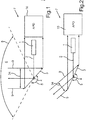
- the laser scanner has an optical transmitter, which comprises a light source 1, in particular a laser source, for emitting beams 2 and a pivotable mirror 3.
- the mirror 3 can be pivoted about a pivot axis 4 according to the arrow 5 in order to deflect the beams 2.
- a field of view 6 of the detection device designated overall by 7 is defined by a scanning angle range 8, in particular in the azimuth direction. Within this scanning angle range 8, the field of view 6 is scanned with the detection device 7, a beam pulse being emitted step by step for a large number of different scanning angles within the scanning angle range 8.
- the detection device 7 receives reflected beams 9 which are deflected onto a photodetector or receiver 10, for example by the same mirror 3. Embodiments without deflecting the reflected rays 9 or with a separate mirror are also possible.
- a time period between two adjacent scanning angles and thus between two temporally adjacent shots which depends on the scanning frequency and the angular resolution.
- This time period is significantly longer than the transit time from the transmission of the pulse to the return of a reception pulse at the maximum measuring distance, which is usually between 200 and 400 m.
- a scan frequency of, for example, 25 Hz and an angular resolution of 0.25 ° lie between two shots and thus between the step movement of the mirror 3 a total of 27 microseconds.
- a distance of, for example, 327 m corresponds to a transit time of the light of only approx. 2.2 ⁇ s, so that there is a period of approx. 23 ⁇ s between the completion of the measurement on one angular step and the start of the next measurement on the next angular step.
- a laser scanner has a dedicated sensitivity curve over the distance.
- the sensitivity in the close range is often several orders of magnitude higher than in the long range or in the far range. This can lead to the detection of virtual, fictitious target objects that actually do not exist: Basically, the aim is to also detect poorly reflecting targets at a great distance. For this reason, the sensitivity of the laser scanner should always be selected to be high, so that such weakly reflecting targets can also be detected at a great distance.
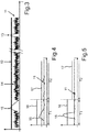
- a correspondingly sensitive measurement setup inevitably leads to the fact that at fictitious targets such as rain and / or fog and / or spray and / or exhaust gas and / or dirt on a cover plate reflected rays are received by the receiver with a relatively high energy and then as real target objects are interpreted. This is because these reflections have such high energy that they are above the detection threshold. If this detection threshold were increased to counteract the problem described, it would lead to a reduced sensitivity of the receiver in the far range, and weakly reflecting target objects at a great distance could no longer be detected. This problem is in Fig. 3 based on a curve of an electrical received signal 11 over time t.
- a detection threshold 12 is set correspondingly low so that real target objects can also be detected from a great distance. Such a target echo 13 of the received signal 11 is then above the detection threshold 12 and can thus be detected by the evaluation device. The noise 14 of the received signal 11 is below the detection threshold 13.
- a low detection threshold 13 inevitably also leads to fictitious target echoes 15 being detected in the close range, which originate from fictitious targets such as rain / fog / spray / exhaust gas / dirt. With such a detection threshold 12, these targets cannot be hidden.
- the detection or masking out of such atmospheric disturbances while maintaining a relatively long measurement range is based in the prior art on the use of several detection thresholds of different heights.
- a higher first detection threshold is used. This detection threshold is chosen so that signals from atmospheric disturbances do not exceed this increased detection threshold in the near range.
- a second detection threshold is used for the long-range measurement, which for example corresponds to the detection threshold 12 Fig. 3 corresponds.
- An exemplary reception signal 11 with a first detection threshold 16 for the near range and a second detection threshold 17 for the far range is shown in FIG Fig. 4 shown.
- the first detection threshold 16 is used during a first time interval T1 after a transmission beam has been emitted.
- the first time interval T1 corresponds, for example, to a close range of 15 m from the motor vehicle.
- the first time interval T1 is then immediately followed by a second time interval T2 in which the second detection threshold 17 is used.
- the two thresholds 16, 17 are each set to a constant value, the first threshold 16 being higher than the second threshold 17.
- a target echo 15 is now masked by an atmospheric disturbance because the height of this target echo 15 is below the first threshold 16.
- Measurements on real objects generally have a significantly higher signal energy and also exceed the increased first detection threshold, as shown in Fig. 5 is shown using a real target echo 18.
- a scanning optoelectronic detection device in particular a laser scanner, is designed to detect a target object in the vicinity of a motor vehicle.
- the detection device comprises an optical transmitter for emitting electromagnetic rays, the transmitter being designed to scan a field of view of the detection device, in particular in the azimuth direction or in the horizontal direction, and to transmit a transmission beam for a large number of different scanning angles within an entire scanning angle range, in particular one laser pulse each.
- the detection device also has an optical receiver which is designed to receive beams reflected in the environment and to provide an electrical reception signal depending on the beams received.
- An electronic evaluation device detects the target object depending on the electrical received signal.
- the evaluation device is designed to compare the received signal with a detection threshold for each scanning angle and to detect the target object depending on the comparison.
- the detection threshold is an angle-dependent threshold value function which has different threshold values for the received signal for at least two different scanning angles of the transmitter.
- a threshold for the received signal instead of a detection threshold that is constant for all scanning angles, at which the respective threshold values with which the level of the Received signal is compared with respect to the detection of a target object.
- the invention is based on the finding that the state of the art does not take into account that a scanning detection device, in particular a laser scanner, can have a varying sensitivity over the entire scanning angle range, depending on the optical design. While the sensitivity is relatively high at some scanning angles of the transmitter, the sensitivity of the detection device is significantly lower at other scanning angles. This is due in particular to the fact that, depending on the scanning angle, different cross-sections of the mirror are available for deflecting the rays reflected in the environment. With a smaller cross-section of the mirror, the received energy of the beams is therefore lower for a given distance than for a larger cross section. With a smaller cross-section, a lower threshold value for the received signal should therefore be defined accordingly in order to be able to ensure that real target objects can be detected.
- the optical transmitter can e.g. have a light source, in particular a laser.
- a source e.g. a diode can be used.
- the transmitter can also comprise a mirror, by means of which the emitted beams are deflected. The mirror can be pivoted. Different angular positions of the mirror then correspond to different scanning angles within the scanning angle range.
- the transmitter is preferably designed to emit a beam pulse, in particular a laser pulse, for each scanning angle.
- the receiver can comprise one or more receiving elements, in particular photodiodes and / or phototransistors.
- Avalanche semiconductor elements in particular avalanche photodiodes, can be used in particular as receiving elements.
- Said or a separate mirror can also be arranged in the received beam path, by means of which the beams reflected in the surroundings are deflected in the direction of the receiver.
- the angle-dependent threshold value function over the entire scanning angle range corresponds to a measuring sensitivity function of the optical receiver which changes or changes over the scanning angle range and which indicates a sensitivity of the receiver for different scanning angles.
- This angle-dependent threshold function can have the form of a quadratic function, which has a maximum in particular for the mean scanning angles and drops in the direction of the two lateral scanning angles in edge regions of the scanning angle range.
- the angle dependence depends on the angle via trigonometric relationships. This can be different for differently designed optical structures. It can thus be ensured that real target objects can also be reliably detected in the edge area of the scanning angle area or in the edge area of the field of view of the detection device, that is to say precisely where the sensitivity of the detection device is low.
- n can range from 2 to 10.
- the evaluation device is designed to first compare the electrical received signal with a first detection threshold provided for a short-range measurement within a first time interval after the transmitter has emitted a transmission beam (for a specific scanning angle), and the electrical one within a second time interval following the first time interval Compare received signal with a second detection threshold provided for a long-range measurement.
- a total of two detection thresholds can therefore be provided, namely on the one hand a first detection threshold for the short-range measurement (for example up to a distance of 10 m to 20 m from the motor vehicle, in particular up to a distance of 15 m) and on the other hand a second detection threshold for the long-range measurement (e.g. from 15 m).
- the above-mentioned angle-dependent threshold value function preferably represents the first detection threshold that is provided for the short-range measurement. It has been found that in the close range up to about 15 m from the motor vehicle, the atmospheric disturbances and possibly also dirt and the like are particularly problematic with regard to the generation of false echoes. In principle, a higher detection threshold should be defined in this close range than in the far range.
- the first detection threshold is thus preferably higher than the second detection threshold over the entire scanning angle range.
- the second detection threshold has a curve that is constant over the entire scanning angle range, so that for all scanning angles the same threshold values for the received signal are preferably predetermined for the long-range measurement.
- the second detection threshold which is used for the long-range measurement, is an angle-dependent threshold value function which has threshold values for the received signal that are different from one another for a plurality of different scanning angles of the transmitter.
- the second detection threshold can thus also be adapted to the angle-dependent sensitivity curve of the receiver, if necessary.
- the first and the second detection threshold are used exclusively for a subset of the scanning angles, in particular for every nth scanning angle, and for the remaining scanning angles only the second detection threshold is used both for the short-range measurement and for the long-range measurement.
- n represents an integer from a range of values from 2 to 10. This reduces the effort involved in switching between the two thresholds, since it is not necessary to switch between the two thresholds at all scanning angles and the resolution of the system in the close range is not that great Role as shown in the far field.
- a motor vehicle according to the invention comprises a detection device according to the invention.
- the motor vehicle is preferably a passenger car.
- the invention also relates to a method for operating a scanning optoelectronic detection device, which has the features of the independent method claim.
- a detection device 7 comprises a receiver 10 which is designed as an avalanche photodetector.
- An amplifier circuit is also integrated in the receiver 10.
- the receiver 10 receives the rays 9 reflected in the environment and provides an analog electrical reception signal 19, the level of which is dependent on the energy of the rays 9.
- the received electrical signal is fed to an analog comparator 20, which also receives an analog threshold signal 21.
- This threshold value signal 21 depending on the respective time interval T1, T2 according to the 4 and 5 -
- the first detection threshold 16 or the second detection threshold 17 alternately.
- the comparator 20 outputs at its output a binarized electrical reception signal 22 which is fed to a unit 23 which, depending on the reception signal 22, measures the distance from the target object. Distance measurements 24 are output at the output of the unit 23.
- the comparator 20 and the unit 23 together form an electronic evaluation device 25.
- the analog threshold value signal 21 is provided by means of a digital-analog converter 26 from a digital threshold value signal 27 and is output to the comparator 20.
- a control device 28 is provided, which is connected to a memory 29.
- a table is stored in the memory 29 in which each scanning angle of the transmitter or a different threshold value for the comparator 20 is assigned to each nth scanning angle.
- the control device 28 receives the current scanning angle 31 in the azimuth direction from an angle encoder 30.
- the angle encoder 30 is connected to a scan motor 32, which according to the pivoting of the mirror 3 Fig. 1 is trained.
- the control device 28 reads out the assigned threshold value 33 from the memory 29 and generates the digital threshold value signal 27, which characterizes the current angle-dependent threshold value 33.
- a threshold value signal 21 is present at the comparator 20, the level of which corresponds to the current threshold value, which is selected individually for the current scanning angle.
- the angle-dependent threshold value function is preferably used for the short-range measurement, ie for the first time interval T1 according to the 4 and 5 .
- the second detection threshold 17 can also be set for the second time interval T2 or for the long-range measurement depending on the angle or depending on the current scanning angle.
- the angle-dependent setting of the detection threshold 16 is based on the fact that the sensitivity of the receiver 10 is also angle-dependent and varies over the entire scanning angle range 8. Referring to the 1 and 2 there is a different cross section of the mirror 3 for each scanning angle of the transmitter from the point of view of the received beams 9, as shown in FIGS 1 and 2 a total of 34 is indicated. This means that at different scanning angles, different cross sections 34 of the mirror 3 are available for the beams 9 reflected in the environment. A different energy of the beams 9 is thus given for each scanning angle.
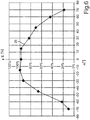
- the detection device 7 thus has an angle-dependent (in the azimuth direction) sensitivity function.
- An example sensitivity function 35 is shown in FIG Fig. 6 shown.
- This function 35 is standardized or represents a relative sensitivity function Fig. 6 function 35 essentially or approximately has the shape of a quadratic function with a maximum in the central region of the scanning angle range 8.
- the scanning angle ⁇ is plotted on the x-axis, while the relative sensitivity E in% is plotted on the y-axis. is applied.
- the sensitivity is lowest in the respective edge regions of the entire azimuthal scanning angle region 8.
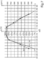
- the angle-dependent threshold value function for the detection threshold 16 is now adapted to the course of the sensitivity function 35.
- Fig. 7 a comparison of the sensitivity function 35 with an angle-dependent threshold value function 36 is shown.
- the scale shown on the right-hand side applies to the threshold value function 36 and thus indicates the level of the threshold values S in mV.
- the curve of the threshold value function 36 corresponds to that of the sensitivity function 35, so that the two curves overlap at least approximately.
- the two functions are also essentially symmetrical with respect to the scanning angle 0 ° and fall evenly on both sides.
Landscapes
- Engineering & Computer Science (AREA)
- Physics & Mathematics (AREA)
- Computer Networks & Wireless Communication (AREA)
- General Physics & Mathematics (AREA)
- Radar, Positioning & Navigation (AREA)
- Remote Sensing (AREA)
- Electromagnetism (AREA)
- Optical Radar Systems And Details Thereof (AREA)
Description
Die Erfindung betrifft eine abtastende optoelektronische Detektionseinrichtung, insbesondere einen Laserscanner, für ein Kraftfahrzeug, mit einem optischen Sender zum Aussenden elektromagnetischer Strahlen in einen Umgebungsbereich des Kraftfahrzeugs, mit einem optischen Empfänger zum Empfangen von im Umgebungsbereich reflektierten Strahlen und zum Bereitstellen eines elektrischen Empfangssignals abhängig von den empfangenen Strahlen, und mit einer Auswerteeinrichtung zum Detektieren eines Zielobjekts im Umgebungsbereich abhängig von dem elektrischen Empfangssignal. Der Sender ist dazu ausgebildet, für eine Vielzahl von unterschiedlichen Abtastwinkeln innerhalb eines gesamten Abtastwinkelbereiches, insbesondere in Azimutrichtung bzw. in horizontaler Richtung, jeweils einen Sendestrahl auszusenden. Die Auswerteeinrichtung ist dazu ausgelegt, für jeden Abtastwinkel die Höhe des Empfangssignals mit einer Detektionsschwelle zu vergleichen und das Zielobjekt abhängig von dem Vergleich zu detektieren. Die Erfindung betrifft außerdem ein Kraftfahrzeugs mit einer solchen Einrichtung, wie auch ein Verfahren zum Betreiben einer Detektionseinrichtung eines Kraftfahrzeugs.The invention relates to a scanning optoelectronic detection device, in particular a laser scanner, for a motor vehicle, with an optical transmitter for emitting electromagnetic radiation into a surrounding area of the motor vehicle, with an optical receiver for receiving beams reflected in the surrounding area and for providing an electrical reception signal depending on the received beams, and with an evaluation device for detecting a target object in the vicinity depending on the electrical received signal. The transmitter is designed to emit a transmission beam for a large number of different scanning angles within an entire scanning angle range, in particular in the azimuth direction or in the horizontal direction. The evaluation device is designed to compare the height of the received signal with a detection threshold for each scanning angle and to detect the target object depending on the comparison. The invention also relates to a motor vehicle with such a device, and also to a method for operating a detection device of a motor vehicle.
Unterschiedlichste Fahrerassistenzsysteme zur Detektion von Objekten werden zunehmend im Automobilbereich eingesetzt, um den Fahrer beim Führen seines Kraftfahrzeugs zu unterstützen. Laser-basierte Systeme (auch unter der Bezeichnung "Lidar" bzw. "Light Detection and Ranging" bekannt) ermöglichen dabei die Erkennung von Objekten in einer relativ großen Reichweite bis über 100 m vom Fahrzeug mit einer sehr hohen Messgenauigkeit. Sie werden bevorzugt im vorderen Bereich des Fahrzeugs platziert, beispielsweise hinter der Windschutzscheibe oder aber am Kühlergrill, um u.a. die Zeit bis zum Aufprall (time to collision, TTC) zu ermitteln. Solche Systeme können aber auch in seitigen oder rückwärtigen Bereichen des Fahrzeugs platziert werden, um den Totwinkel bzw. rückwärtigen Verkehr zu überwachen.A wide variety of driver assistance systems for the detection of objects are increasingly being used in the automotive field in order to support the driver in driving his motor vehicle. Laser-based systems (also known under the name "Lidar" or "Light Detection and Ranging") enable the detection of objects in a relatively large range up to over 100 m from the vehicle with a very high measurement accuracy. They are preferably placed in the front area of the vehicle, for example behind the windshield or on the radiator grille, for example to determine the time to collision (TTC). Such systems can also be placed in the side or rear areas of the vehicle to monitor the blind spot or rear traffic.
Ein Laserscanner arbeitet nach dem Lichtlaufzeitprinzip und beinhaltet typischerweise einen optischen Sender, welcher kurze Laserimpulse aussendet, die über einen schwenkbaren Spiegel so abgelenkt werden, dass eine Abtastung des gesamten Sichtfelds innerhalb eines vorbestimmten Abtastwinkelbereiches stattfindet. Pro Abtastwinkel bzw. pro Winkelschritt wird dabei ein Laserimpuls ausgesendet. Im selben Winkelschritt, ohne dass der Spiegel bewegt wird, werden die reflektierten Strahlen mittels eines Empfängers empfangen, und es wird ein elektrisches Empfangssignal bereitgestellt. Dieses elektrische Empfangssignal wird analysiert. Werden Echos bzw. Pulse im Empfangssignal erkannt, so sind diese grundsätzlich auf Reflektionen des ausgesendeten Laserimpulses an Zielobjekten in der Umgebung zurückzuführen. Die Zeitdauer zwischen dem Aussenden des Laserimpulses und dem Empfangen des Echos ist proportional zur Distanz zum Objekt. Diese Laufzeit wird gemessen und als Ergebnis der Entfernungsmessung für diesen Winkelschritt abgelegt.A laser scanner works on the time-of-flight principle and typically includes an optical transmitter that emits short laser pulses that are deflected by a pivotable mirror so that the entire field of view is scanned within a predetermined scanning angle range. One laser pulse is emitted per scanning angle or per angular step. At the same angular step, without moving the mirror, the reflected rays received by means of a receiver, and an electrical reception signal is provided. This electrical received signal is analyzed. If echoes or pulses are detected in the received signal, these are basically due to reflections of the emitted laser pulse on target objects in the area. The time between sending the laser pulse and receiving the echo is proportional to the distance to the object. This transit time is measured and stored as the result of the distance measurement for this angular step.
Ein Laserscanner für Kraftfahrzeuge ist beispielsweise aus dem Dokument
In der
Die
Im Dokument
In der
In dem Patent
Ein beispielhafter Laserscanner ist in schematischer und abstrakter Darstellung auch in
Zwischen zwei benachbarten Abtastwinkeln und somit zwischen zwei zeitlich benachbarten Schüssen liegt eine Zeitspanne, die von der Scanfrequenz und der Winkelauflösung abhängt. Diese Zeitspanne ist deutlich größer als die Laufzeit vom Aussenden des Pulses bis zur Rückkehr eines Empfangspulses in der maximalen Messentfernung, welche üblicherweise zwischen 200 und 400 m liegt. Bei einer Scanfrequenz von beispielsweise 25 Hz und einer Winkelauflösung von 0,25° liegen zwischen zwei Schüssen und somit zwischen der Schrittbewegung des Spiegels 3 insgesamt 27 µs. Eine Entfernung von beispielsweise 327 m entspricht einer Laufzeit des Lichts von lediglich ca. 2,2 µs, so dass zwischen dem Abschluss der Messung auf einem Winkelschritt und dem Beginn der nächsten Messung auf dem nächsten Winkelschritt eine Zeitspanne von ca. 23 µs verbleibt.There is a time period between two adjacent scanning angles and thus between two temporally adjacent shots, which depends on the scanning frequency and the angular resolution. This time period is significantly longer than the transit time from the transmission of the pulse to the return of a reception pulse at the maximum measuring distance, which is usually between 200 and 400 m. At a A scan frequency of, for example, 25 Hz and an angular resolution of 0.25 ° lie between two shots and thus between the step movement of the mirror 3 a total of 27 microseconds. A distance of, for example, 327 m corresponds to a transit time of the light of only approx. 2.2 μs, so that there is a period of approx. 23 μs between the completion of the measurement on one angular step and the start of the next measurement on the next angular step.
Ein Laserscanner besitzt abhängig von seinem optischen Aufbau einen dedizierten Empfindlichkeitsverlauf über die Entfernung. Die Empfindlichkeit im Nahbereich ist dabei oft um mehrere Zehnerpotenzen höher als in großer Entfernung bzw. im Fernbereich. Dies kann zur Detektion von virtuellen, fiktiven Zielobjekten führen, die tatsächlich nicht existieren: Grundsätzlich wird angestrebt, auch schlecht reflektierende Ziele in großer Entfernung zu detektieren. Deshalb soll die Empfindlichkeit des Laserscanners grundsätzlich hoch gewählt werden, damit auch solche schwach reflektierenden Ziele in großer Entfernung detektiert werden können. Ein entsprechend empfindlicher Messaufbau führt jedoch zwangsläufig auch dazu, dass an fiktiven Zielen, wie Regen und/oder Nebel und/oder Gischt und/oder Abgas und/oder Schmutz auf einer Abdeckscheibe reflektierte Strahlen mit einer relativ hohen Energie durch den Empfänger empfangen und dann als echte Zielobjekte interpretiert werden. Diese Reflexionen weisen nämlich eine solchermaßen hohe Energie auf, dass sie oberhalb der Detektionsschwelle liegen. Würde man diese Detektionsschwelle erhöhen, um der beschriebenen Problematik entgegenzuwirken, so würde es zu einer reduzierten Empfindlichkeit des Empfängers im Fernbereich führen, und schwach reflektierende Zielobjekte in großer Entfernung könnten nicht mehr detektiert werden. Diese Problematik ist in
Die Erkennung bzw. Ausblendung solcher atmosphärischer Störungen unter Beibehaltung einer relativ hohen Messreichweite basiert im Stand der Technik auf der Verwendung mehrerer Detektionsschwellen unterschiedlicher Höhe. Im Nahbereich, der besonders sensibel hinsichtlich Messungen auf atmosphärische Störungen ist, kommt eine höhere erste Detektionsschwelle zum Einsatz. Diese Detektionsschwelle wird so gewählt, dass Signale atmosphärischer Störungen diese erhöhte Detektionsschwelle im Nahbereich nicht übersteigen. Für die Fernbereichsmessung wird dabei eine zweite Detektionsschwelle verwendet, welche beispielsweise der Detektionsschwelle 12 gemäß
Es hat sich jedoch herausgestellt, dass die Verwendung einer konstanten erhöhten Detektionsschwelle im Nahbereich zu suboptimalen Ergebnissen führt, weil bei unterschiedlichen Situationen das Zielecho 18 von einem echten Zielobjekt im Nahbereich aufgrund der erhöhten Detektionsschwelle 16 nicht detektiert werden kann.However, it has been found that the use of a constant increased detection threshold in the close range leads to suboptimal results, because in different situations the
Es ist Aufgabe der Erfindung, eine Lösung aufzuzeigen, wie bei einer Detektionseinrichtung der eingangs genannten Gattung einerseits die Empfindlichkeit, insbesondere im Nahbereich, im Vergleich zum Stand der Technik erhöht werden kann und andererseits auch sichergestellt werden kann, dass Zielechos ausgeblendet werden können, die von atmosphärischen Störungen stammen.It is an object of the invention to provide a solution of how, in the case of a detection device of the type mentioned at the outset, on the one hand the sensitivity, in particular in the close range, can be increased compared to the prior art and on the other hand it can also be ensured that target echoes can be masked out atmospheric disturbances.
Diese Aufgabe wird erfindungsgemäß durch eine Detektionseinrichtung, durch ein Kraftfahrzeug sowie durch ein Verfahren mit den Merkmalen gemäß den jeweiligen unabhängigen Patentansprüchen gelöst. Vorteilhafte Ausführungen der Erfindung sind Gegenstand der abhängigen Patentansprüche, der Beschreibung und der Figuren.This object is achieved according to the invention by a detection device, by a motor vehicle and by a method with the features according to the respective independent patent claims. Advantageous embodiments of the invention are the subject of the dependent claims, the description and the figures.
Eine erfindungsgemäße abtastende optoelektronische Detektionseinrichtung, insbesondere Laserscanner, ist zur Detektion eines Zielobjektes in der Umgebung eines Kraftfahrzeugs ausgebildet. Die Detektionseinrichtung umfasst einen optischen Sender zum Aussenden elektromagnetischer Strahlen, wobei der Sender dazu ausgebildet ist, ein Sichtfeld der Detektionseinrichtung, insbesondere in Azimutrichtung bzw. in horizontaler Richtung, abzutasten und hierbei für eine Vielzahl von unterschiedlichen Abtastwinkeln innerhalb eines gesamten Abtastwinkelbereiches jeweils einen Sendestrahl auszusenden, insbesondere jeweils einen Laserimpuls. Die Detektionseinrichtung hat auch einen optischen Empfänger, welcher zum Empfangen von in der Umgebung reflektierten Strahlen und zum Bereitstellen eines elektrischen Empfangssignals abhängig von den empfangenen Strahlen ausgebildet ist. Eine elektronische Auswerteeinrichtung detektiert das Zielobjekt abhängig von dem elektrischen Empfangssignal. Die Auswerteeinrichtung ist dabei dazu ausgelegt, für jeden Abtastwinkel das Empfangssignal mit einer Detektionsschwelle zu vergleichen und das Zielobjekt abhängig von dem Vergleich zu detektieren. Die Detektionsschwelle ist eine winkelabhängige Schwellwertfunktion, welche für zumindest zwei unterschiedliche Abtastwinkel des Senders voneinander unterschiedliche Schwellwerte für das Empfangssignal aufweist.A scanning optoelectronic detection device according to the invention, in particular a laser scanner, is designed to detect a target object in the vicinity of a motor vehicle. The detection device comprises an optical transmitter for emitting electromagnetic rays, the transmitter being designed to scan a field of view of the detection device, in particular in the azimuth direction or in the horizontal direction, and to transmit a transmission beam for a large number of different scanning angles within an entire scanning angle range, in particular one laser pulse each. The detection device also has an optical receiver which is designed to receive beams reflected in the environment and to provide an electrical reception signal depending on the beams received. An electronic evaluation device detects the target object depending on the electrical received signal. The evaluation device is designed to compare the received signal with a detection threshold for each scanning angle and to detect the target object depending on the comparison. The detection threshold is an angle-dependent threshold value function which has different threshold values for the received signal for at least two different scanning angles of the transmitter.
Erfindungsgemäß wird demnach vorgeschlagen, statt einer für alle Abtastwinkel konstanten Detektionsschwelle eine solche Schwelle für das Empfangssignal vorzusehen, bei welcher für zumindest zwei unterschiedliche Abtastwinkel, insbesondere für eine Vielzahl größer 2 von unterschiedlichen Abtastwinkeln, die jeweiligen Schwellwerte voneinander unterschiedlich sind, mit denen die Höhe des Empfangssignals jeweils im Hinblick auf die Detektion eines Zielobjektes verglichen wird. Auf diese Weise gelingt es, einerseits die maximal mögliche Empfindlichkeit der Detektionseinrichtung, insbesondere im Nahbereich, zu ermöglichen und andererseits auch zu gewährleisten, dass Scheinechos ausgeblendet werden können, welche von atmosphärischen Störungen stammen, wie beispielsweise Nebel und/oder Gischt und/oder Regen und/oder Abgase und dergleichen. Die Erfindung basiert dabei auf der Erkenntnis, dass im Stand der Technik nicht berücksichtigt wird, dass eine abtastende Detektionseinrichtung, insbesondere ein Laserscanner, je nach optischem Aufbau über den gesamten Abtastwinkelbereich eine variierende Empfindlichkeit besitzen kann. Während bei manchen Abtastwinkeln des Senders die Empfindlichkeit relativ hoch ist, ist bei anderen Abtastwinkeln die Empfindlichkeit der Detektionseinrichtung deutlich geringer. Dies ist insbesondere darauf zurückzuführen, dass je nach Abtastwinkel unterschiedliche Querschnitte des Spiegels für die Umlenkung der in der Umgebung reflektierten Strahlen zur Verfügung stehen. Bei einem geringeren Querschnitt des Spiegels ist die empfangene Energie der Strahlen somit bei einer gegebenen Entfernung geringer als bei einem größeren Querschnitt. Bei einem geringeren Querschnitt sollte deshalb entsprechend ein geringerer Schwellwert für das Empfangssignal definiert werden, um sicherstellen zu können, dass echte Zielobjekte detektiert werden können.According to the invention, it is therefore proposed to provide such a threshold for the received signal instead of a detection threshold that is constant for all scanning angles, at which the respective threshold values with which the level of the Received signal is compared with respect to the detection of a target object. In this way, it is possible on the one hand to enable the maximum possible sensitivity of the detection device, in particular in the close range, and on the other hand to ensure that false echoes can be masked out which come from atmospheric disturbances, such as fog and / or spray and / or rain and / or exhaust gases and the like. The invention is based on the finding that the state of the art does not take into account that a scanning detection device, in particular a laser scanner, can have a varying sensitivity over the entire scanning angle range, depending on the optical design. While the sensitivity is relatively high at some scanning angles of the transmitter, the sensitivity of the detection device is significantly lower at other scanning angles. This is due in particular to the fact that, depending on the scanning angle, different cross-sections of the mirror are available for deflecting the rays reflected in the environment. With a smaller cross-section of the mirror, the received energy of the beams is therefore lower for a given distance than for a larger cross section. With a smaller cross-section, a lower threshold value for the received signal should therefore be defined accordingly in order to be able to ensure that real target objects can be detected.
Der optische Sender kann z.B. eine Lichtquelle, insbesondere einen Laser, aufweisen. Als Quelle kann z.B. eine Diode eingesetzt werden. Der Sender kann auch einen Spiegel umfassen, mittels welchem die ausgesendeten Strahlen umgelenkt werden. Der Spiegel kann schwenkbar gelagert sein. Unterschiedliche Winkelstellungen des Spiegels entsprechen dann unterschiedlichen Abtastwinkeln innerhalb des Abtastwinkelbereiches. Der Sender ist vorzugsweise zum Aussenden jeweils eines Strahlimpulses, insbesondere eines Laserimpulses, für jeden Abtastwinkel ausgebildet.The optical transmitter can e.g. have a light source, in particular a laser. As a source e.g. a diode can be used. The transmitter can also comprise a mirror, by means of which the emitted beams are deflected. The mirror can be pivoted. Different angular positions of the mirror then correspond to different scanning angles within the scanning angle range. The transmitter is preferably designed to emit a beam pulse, in particular a laser pulse, for each scanning angle.
Der Empfänger kann ein oder mehrere Empfangselemente, insbesondere Photodioden und/oder Phototransistoren, umfassen. Als Empfangselemente können insbesondere Avalanche-Halbleiterelemente eingesetzt werden, insbesondere Avalanche-Photodioden. Im Empfangsstrahlengang kann auch der genannte oder ein separater Spiegel angeordnet sein, mittels welchem die in der Umgebung reflektierten Strahlen in Richtung zum Empfänger umgelenkt werden.The receiver can comprise one or more receiving elements, in particular photodiodes and / or phototransistors. Avalanche semiconductor elements, in particular avalanche photodiodes, can be used in particular as receiving elements. Said or a separate mirror can also be arranged in the received beam path, by means of which the beams reflected in the surroundings are deflected in the direction of the receiver.
Es erweist sich als besonders vorteilhaft, wenn die winkelabhängige Schwellwertfunktion über den gesamten Abtastwinkelbereich entsprechend einer sich über den Abtastwinkelbereich ändernden bzw. winkelabhängigen Messempfindlichkeitsfunktion des optischen Empfängers entspricht, welche eine Empfindlichkeit des Empfängers für unterschiedliche Abtastwinkel angibt. Diese winkelabhängige Schwellenfunktion kann die Form einer quadratischen Funktion aufweisen, welche insbesondere für die mittleren Abtastwinkel ein Maximum aufweist und in Richtung zu den beiden seitlichen Abtastwinkeln in Randbereichen des Abtastwinkelbereiches abfällt. Allgemein hängt die Winkelabhängigkeit über trigonometrische Zusammenhänge vom Winkel ab. Das kann für unterschiedlich gestaltete optische Aufbauten anders sein. Somit kann also gewährleistet werden, dass auch echte Zielobjekte im Randbereich des Abtastwinkelbereiches bzw. im Randbereich des Sichtfeldes der Detektionseinrichtung zuverlässig detektiert werden können, also gerade dort, wo die Empfindlichkeit der Detektionseinrichtung gering ist.It has proven to be particularly advantageous if the angle-dependent threshold value function over the entire scanning angle range corresponds to a measuring sensitivity function of the optical receiver which changes or changes over the scanning angle range and which indicates a sensitivity of the receiver for different scanning angles. This angle-dependent threshold function can have the form of a quadratic function, which has a maximum in particular for the mean scanning angles and drops in the direction of the two lateral scanning angles in edge regions of the scanning angle range. In general, the angle dependence depends on the angle via trigonometric relationships. This can be different for differently designed optical structures. It can thus be ensured that real target objects can also be reliably detected in the edge area of the scanning angle area or in the edge area of the field of view of the detection device, that is to say precisely where the sensitivity of the detection device is low.
Beispielsweise ist für jeden oder jeden n-ten Abtastwinkel jeweils ein unterschiedlicher Schwellwert der Detektionsschwelle vorgegeben. n kann dabei in einem Wertebereich von 2 bis 10 liegen.For example, a different threshold value of the detection threshold is specified for each or every nth scanning angle. n can range from 2 to 10.
Vorzugsweise ist die Auswerteeinrichtung dazu ausgelegt, innerhalb eines ersten Zeitintervalls nach Aussenden eines Sendestrahls durch den Sender (für einen bestimmten Abtastwinkel) das elektrische Empfangssignal zunächst mit einer für eine Nahbereichsmessung vorgesehenen ersten Detektionsschwelle zu vergleichen und innerhalb eines auf das erste Zeitintervall folgenden zweiten Zeitintervalls das elektrische Empfangssignal mit einer für eine Fernbereichsmessung vorgesehenen zweiten Detektionsschwelle zu vergleichen. Es können also insgesamt zwei Detektionsschwellen vorgesehen sein, nämlich einerseits eine erste Detektionsschwelle für die Nahbereichsmessung (z.B. bis zu einer Entfernung von 10 m bis 20 m vom Kraftfahrzeug, insbesondere bis zu einer Entfernung von 15 m) und andererseits eine zweite Detektionsschwelle für die Fernbereichsmessung (z.B. ab 15 m). Die oben genannte winkelabhängige Schwellwertfunktion stellt dabei vorzugsweise die erste Detektionsschwelle dar, die für die Nahbereichsmessung vorgesehen ist. Es hat sich nämlich herausgestellt, dass gerade im Nahbereich bis zu etwa 15 m vom Kraftfahrzeug die atmosphärischen Störungen und gegebenenfalls auch Schmutz und dergleichen besonders problematisch im Hinblick auf die Erzeugung von Scheinechos sind. In diesem Nahbereich soll also grundsätzlich eine höhere Detektionsschwelle definiert werden als im Fernbereich. Die erste Detektionsschwelle ist somit über den gesamten Abtastwinkelbereich bevorzugt höher als die zweite Detektionsschwelle.Preferably, the evaluation device is designed to first compare the electrical received signal with a first detection threshold provided for a short-range measurement within a first time interval after the transmitter has emitted a transmission beam (for a specific scanning angle), and the electrical one within a second time interval following the first time interval Compare received signal with a second detection threshold provided for a long-range measurement. A total of two detection thresholds can therefore be provided, namely on the one hand a first detection threshold for the short-range measurement (for example up to a distance of 10 m to 20 m from the motor vehicle, in particular up to a distance of 15 m) and on the other hand a second detection threshold for the long-range measurement ( e.g. from 15 m). The above-mentioned angle-dependent threshold value function preferably represents the first detection threshold that is provided for the short-range measurement. It has been found that in the close range up to about 15 m from the motor vehicle, the atmospheric disturbances and possibly also dirt and the like are particularly problematic with regard to the generation of false echoes. In principle, a higher detection threshold should be defined in this close range than in the far range. The first detection threshold is thus preferably higher than the second detection threshold over the entire scanning angle range.
Während die erste Detektionsschwelle - wie ausgeführt - durch die winkelabhängige Schwellwertfunktion gebildet ist, weist die zweite Detektionsschwelle in einer Ausführungsform einen über den gesamten Abtastwinkelbereich konstanten Verlauf auf, so dass für alle Abtastwinkel bevorzugt gleiche Schwellwerte für das Empfangssignal bei der Fernbereichsmessung vorgegeben sind.While the first detection threshold - as stated - is formed by the angle-dependent threshold value function, in one embodiment the second detection threshold has a curve that is constant over the entire scanning angle range, so that for all scanning angles the same threshold values for the received signal are preferably predetermined for the long-range measurement.
Alternativ kann jedoch auch vorgesehen sein, dass auch die zweite Detektionsschwelle, welche für die Fernbereichsmessung angewendet wird, eine winkelabhängige Schwellwertfunktion ist, welche für eine Mehrzahl von unterschiedlichen Abtastwinkeln des Senders voneinander unterschiedliche Schwellwerte für das Empfangssignal aufweist. Somit kann auch die zweite Detektionsschwelle an den winkelabhängigen Empfindlichkeitsverlauf des Empfängers gegebenenfalls angepasst werden.Alternatively, however, it can also be provided that the second detection threshold, which is used for the long-range measurement, is an angle-dependent threshold value function which has threshold values for the received signal that are different from one another for a plurality of different scanning angles of the transmitter. The second detection threshold can thus also be adapted to the angle-dependent sensitivity curve of the receiver, if necessary.
Es kann auch vorgesehen sein, dass ausschließlich für eine Untermenge der Abtastwinkel, insbesondere für jeden n-ten Abtastwinkel, die erste und die zweite Detektionsschwelle und für die übrigen Abtastwinkel ausschließlich die zweite Detektionsschwelle sowohl für die Nahbereichsmessung als auch für die Fernbereichsmessung angewendet wird. n stellt dabei eine ganze Zahl aus einem Wertebereich von 2 bis 10 dar. Somit reduziert sich der Aufwand bei der Umschaltung zwischen den beiden Schwellen, da nicht bei allen Abtastwinkeln zwischen den beiden Schwellen umgeschaltet werden muss und die Auflösung des Systems im Nahbereich keine so große Rolle wie im Fernbereich darstellt.It can also be provided that the first and the second detection threshold are used exclusively for a subset of the scanning angles, in particular for every nth scanning angle, and for the remaining scanning angles only the second detection threshold is used both for the short-range measurement and for the long-range measurement. n represents an integer from a range of values from 2 to 10. This reduces the effort involved in switching between the two thresholds, since it is not necessary to switch between the two thresholds at all scanning angles and the resolution of the system in the close range is not that great Role as shown in the far field.
Ein erfindungsgemäßes Kraftfahrzeug umfasst eine erfindungsgemäße Detektionseinrichtung. Das Kraftfahrzeug ist bevorzugt ein Personenkraftwagen.A motor vehicle according to the invention comprises a detection device according to the invention. The motor vehicle is preferably a passenger car.
Die Erfindung betrifft auch ein Verfahren zum Betreiben einer abtastenden optoelektronischen Detektionseinrichtung, welches die Merkmale des unabhängigen Verfahrensanspruchs aufweist.The invention also relates to a method for operating a scanning optoelectronic detection device, which has the features of the independent method claim.
Die mit Bezug auf die erfindungsgemäße Detektionseinrichtung vorgestellten bevorzugten Ausführungsformen und deren Vorteile gelten entsprechend für das erfindungsgemäße Kraftfahrzeug sowie für das erfindungsgemäße Verfahren.The preferred embodiments presented with reference to the detection device according to the invention and their advantages apply accordingly to the motor vehicle according to the invention and to the method according to the invention.
Weitere Merkmale der Erfindung ergeben sich aus den Ansprüchen, den Figuren und der Figurenbeschreibung. Alle vorstehend in der Beschreibung genannten Merkmale und Merkmalskombinationen sowie die nachfolgend in der Figurenbeschreibung genannten und/oder in den Figuren alleine gezeigten Merkmale und Merkmalskombinationen sind nicht nur in der jeweils angegebenen Kombination, sondern auch in anderen Kombinationen oder aber in Alleinstellung verwendbar.Further features of the invention result from the claims, the figures and the description of the figures. All of the features and combinations of features mentioned above in the description and the features and combinations of features mentioned below in the description of the figures and / or shown alone in the figures can be used not only in the respectively specified combination but also in other combinations or on their own.
Die Erfindung wird nun anhand eines bevorzugten Ausführungsbeispiels sowie unter Bezugnahme auf die beigefügten Zeichnungen näher erläutert. Es zeigen:
- Fig. 1
- in schematischer und abstrakter Darstellung eine Detektionseinrichtung gemäß einer Ausführungsform;
- Fig. 2
- in schematischer Darstellung die Detektionseinrichtung gemäß
Fig. 1 , wobei ein anderer Abtastwinkel eines Spiegels eingestellt ist, um unterschiedliche wirksame Querschnitte eines Spiegels zu veranschaulichen; - Fig. 3 bis Fig. 5
- beispielhafte zeitliche Verläufe eines elektrischen Empfangssignals mit Detektionsschwellen;
- Fig. 6
- eine beispielhafte winkelabhängige Empfindlichkeitsfunktion des Empfängers;
- Fig. 7
- eine winkelabhängige Schwellwertfunktion gemäß einer Ausführungsform der Erfindung, wobei die Schwellwertfunktion an die Empfindlichkeitsfunktion angepasst ist; und
- Fig. 8
- ein Blockschaltbild einer Detektionseinrichtung gemäß einer Ausführungsform der Erfindung.
- Fig. 1
- in a schematic and abstract representation of a detection device according to an embodiment;
- Fig. 2
- in a schematic representation the detection device according to
Fig. 1 , where another scanning angle of a mirror is set to illustrate different effective cross sections of a mirror; - 3 to 5
- exemplary temporal profiles of an electrical received signal with detection thresholds;
- Fig. 6
- an exemplary angle-dependent sensitivity function of the receiver;
- Fig. 7
- an angle-dependent threshold value function according to an embodiment of the invention, the threshold value function being adapted to the sensitivity function; and
- Fig. 8
- a block diagram of a detection device according to an embodiment of the invention.
Bezug nehmend auf
Das analoge Schwellwertsignal 21 wird mittels eines Digital-Analog-Wandlers 26 aus einem digitalen Schwellwertsignal 27 bereitgestellt und an den Komparator 20 abgegeben. Zur Bereitstellung des digitalen Schwellwertsignals 27 ist eine Steuereinrichtung 28 vorgesehen, welche mit einem Speicher 29 in Verbindung steht. In dem Speicher 29 ist eine Tabelle abgelegt, in welcher jedem Abtastwinkel des Senders oder jedem n-ten Abtastwinkel jeweils ein unterschiedlicher Schwellwert für den Komparator 20 zugeordnet ist. Die Steuereinrichtung 28 empfängt von einem Winkelencoder 30 den aktuellen Abtastwinkel 31 in Azimutrichtung. Der Winkelencoder 30 steht dabei mit einem Scanmotor 32 in Verbindung, der zum Verschwenken des Spiegels 3 gemäß
Folglich liegt am Komparator 20 ein Schwellwertsignal 21 an, dessen Höhe dem aktuellen Schwellwert entspricht, der für den aktuellen Abtastwinkel individuell gewählt ist.Consequently, a
Die winkelabhängige Schwellwertfunktion wird vorzugsweise für die Nahbereichsmessung verwendet, d.h. für das erste Zeitintervall T1 gemäß den
Die winkelabhängige Einstellung der Detektionsschwelle 16 beruht darauf, dass die Empfindlichkeit des Empfängers 10 auch winkelabhängig ist und über den gesamten Abtastwinkelbereich 8 variiert. Bezug nehmend auf die
Die Detektionseinrichtung 7 weist also eine winkelabhängige (in Azimutrichtung) Empfindlichkeitsfunktion auf. Eine beispielhafte Empfindlichkeitsfunktion 35 ist in
Die winkelabhängige Schwellwertfunktion für die Detektionsschwelle 16 wird nun an den Verlauf der Empfindlichkeitsfunktion 35 angepasst. In
Claims (8)
- Scanning optoelectronic detection device (7), designed as a laser scanner, for a motor vehicle, having an optical transmitter (1, 3) for transmitting electromagnetic beams (2), having an optical receiver (10) for receiving beams (9) reflected from a target object in surroundings of the motor vehicle and for providing an electrical reception signal (19) on the basis of the received beams (9), and having an evaluation device (25) for detecting the target object on the basis of the electrical reception signal (19), wherein the transmitter (1, 3) is designed to transmit a respective transmission beam (2) for a multiplicity of different scanning angles (α) within an overall scanning angle range (8), and wherein the evaluation device (25) is designed, for each scanning angle (α), to compare the reception signal (19) with a detection threshold (16, 17) and to detect the target object on the basis of the comparison,
characterized in that
the detection threshold (16, 17) is an angle-dependent threshold function (36) that has different threshold values (S) for the reception signal (19) for at least two different scanning angles (α) of the transmitter (1, 3). - Detection device (7) according to Claim 1,
characterized in that
the profile of the threshold value function (36) corresponds to the profile of an angle-dependent sensitivity function (35) of the receiver (10) that specifies a sensitivity (E) of the receiver (10) for different scanning angles (α). - Detection device (7) according to Claim 1 or 2,
characterized in that
the evaluation device (25) is designed to compare the electrical reception signal (19) with a first detection threshold (16), provided for a short-range measurement, within a first time interval (T1) following the transmission of a transmission beam (2) by the transmitter (1, 3), and to compare the electrical reception signal (19) with a second detection threshold (17), provided for a long-range measurement, within a second time interval (T2) following the first time interval (T1), and in that the first detection threshold (16) is the angle-dependent threshold value function (36) . - Detection device (7) according to Claim 3,
characterized in that
only the first detection threshold (16) is an angle-dependent threshold value function (36). - Detection device (7) according to Claim 3,
characterized in that
the second detection threshold (17) is also an angle-dependent threshold value function (36). - Detection device (7) according to one of Claims 3 to 5,
characterized in that
the evaluation device (25) is designed to use the first and the second detection threshold (16, 17) only for a subset of the scanning angles (α), in particular for each nth scanning angle (α) and, for the rest of the scanning angles (α), to use only the second detection threshold (17) both for the short-range measurement and for the long-range measurement, wherein n is an integer from a value range from 2 to 10. - Motor vehicle having a detection device (7) according to one of the preceding claims.
- Method for operating a scanning optoelectronic detection device (7), designed as a laser scanner, of a motor vehicle, in which electromagnetic beams (2) are transmitted by way of an optical transmitter (1, 3), beams (9) reflected from a target object in surroundings of the motor vehicle are received by way of an optical receiver (10) and an electrical reception signal (19) is provided on the basis of the received beams (9), and the target object is detected on the basis of the electrical reception signal (19) by way of an evaluation device (25), wherein the transmitter (1, 3) transmits a respective transmission beam (2) for a multiplicity of different scanning angles (α) within an overall scanning angle range (8), and wherein the evaluation device (25), for each scanning angle (α), compares the reception signal (19) with a detection threshold (16, 17) and detects the target object on the basis of the comparison,
characterized in that
an angle-dependent threshold value function (36) is predefined as detection threshold (16, 17), in which different threshold values (S) are predefined for the reception signal (19) for at least two different scanning angles (α) of the transmitter (1, 3).
Applications Claiming Priority (2)
| Application Number | Priority Date | Filing Date | Title |
|---|---|---|---|
| DE102012021831.1A DE102012021831A1 (en) | 2012-11-08 | 2012-11-08 | Scanning opto-electronic detection device with a detection threshold, Kraftfahrzeg and corresponding method |
| PCT/EP2013/069371 WO2014072105A1 (en) | 2012-11-08 | 2013-09-18 | Scanning optoelectronic detection device with a detection threshold, motor vehicle and corresponding method |
Publications (2)
| Publication Number | Publication Date |
|---|---|
| EP2917756A1 EP2917756A1 (en) | 2015-09-16 |
| EP2917756B1 true EP2917756B1 (en) | 2020-04-29 |
Family
ID=49182276
Family Applications (1)
| Application Number | Title | Priority Date | Filing Date |
|---|---|---|---|
| EP13762865.7A Active EP2917756B1 (en) | 2012-11-08 | 2013-09-18 | Scanning optoelectronic detection device with a detection threshold, motor vehicle and corresponding method |
Country Status (4)
| Country | Link |
|---|---|
| US (1) | US9864047B2 (en) |
| EP (1) | EP2917756B1 (en) |
| DE (1) | DE102012021831A1 (en) |
| WO (1) | WO2014072105A1 (en) |
Families Citing this family (23)
| Publication number | Priority date | Publication date | Assignee | Title |
|---|---|---|---|---|
| EP2966473B1 (en) | 2014-07-11 | 2016-11-30 | Sick Ag | Method for measuring an object |
| DE102014223900A1 (en) * | 2014-11-24 | 2016-05-25 | Conti Temic Microelectronic Gmbh | Vehicle environment scanning using a phased array laser |
| CN107430193B (en) * | 2014-12-22 | 2020-08-07 | 特林布尔有限公司 | Distance measuring instrument |
| DE102015104961A1 (en) * | 2015-03-31 | 2016-10-06 | Valeo Schalter Und Sensoren Gmbh | Motor vehicle with object detection and object marking |
| DE102015104951A1 (en) * | 2015-03-31 | 2016-10-06 | Valeo Schalter Und Sensoren Gmbh | Motor vehicle sensor device with adjustable sensitivity |
| EP3088915B1 (en) * | 2015-04-29 | 2021-07-14 | HENSOLDT Sensors GmbH | A method for the determination of a plurality of distinct echo pulses in order to provide distance measurements by an active 3d sensor |
| EP3091342A1 (en) * | 2015-05-07 | 2016-11-09 | Conti Temic microelectronic GmbH | Optical sensor device for a vehicle |
| JP6676916B2 (en) * | 2015-10-05 | 2020-04-08 | 船井電機株式会社 | measuring device |
| WO2017221909A1 (en) * | 2016-06-21 | 2017-12-28 | コニカミノルタ株式会社 | Distance measuring device |
| DE102016112471A1 (en) | 2016-07-07 | 2018-01-11 | Valeo Schalter Und Sensoren Gmbh | Electronic evaluation device of a detection device, detection device, driver assistance system and method for operating an electronic evaluation device |
| JP6925844B2 (en) * | 2017-04-06 | 2021-08-25 | 京セラ株式会社 | Electromagnetic wave detectors, programs, and electromagnetic wave detection systems |
| WO2018226541A1 (en) * | 2017-06-08 | 2018-12-13 | Downunder Geosolutions Pty Ltd. | Method for improved processing of data with time overlapping recordings of energy sources |
| EP3667368B1 (en) * | 2017-08-09 | 2024-04-10 | Pioneer Corporation | Sensor control device |
| DE102018204858B4 (en) | 2018-03-29 | 2023-12-07 | Robert Bosch Gmbh | LiDAR system |
| DE102018123940B4 (en) * | 2018-09-27 | 2023-06-15 | Blickfeld GmbH | Method and device for determining distance |
| DE102018220839B4 (en) * | 2018-12-03 | 2024-07-04 | Pepperl+Fuchs Se | Measuring method and measuring equipment |
| DE102018222426A1 (en) | 2018-12-20 | 2020-06-25 | Robert Bosch Gmbh | Coaxial macro scanner system |
| DE102019200764A1 (en) | 2019-01-23 | 2020-07-23 | Robert Bosch Gmbh | Optical system, in particular LiDAR system, and vehicle |
| DE102019128907A1 (en) * | 2019-10-25 | 2021-04-29 | Valeo Schalter Und Sensoren Gmbh | Filtering of measurement data from an active optical sensor system |
| CN111736135B (en) * | 2020-05-12 | 2023-08-04 | 惠州市德赛西威汽车电子股份有限公司 | Performance detection method, system and equipment of infrared detection equipment |
| CN112698324B (en) * | 2020-12-07 | 2023-10-24 | 南京工业职业技术大学 | Sum and difference single pulse angle measurement method of frequency modulation stepping radar |
| EP4283331A1 (en) * | 2022-05-24 | 2023-11-29 | Sick Ag | Optical detection and distance measurement |
| DE102023110514A1 (en) | 2023-04-25 | 2024-10-31 | Valeo Detection Systems GmbH | OPTICAL ARRANGEMENT, LIDAR SYSTEM INCLUDING THE OPTICAL ARRANGEMENT AND METHOD FOR OPERATING THE LIDAR SYSTEM |
Citations (1)
| Publication number | Priority date | Publication date | Assignee | Title |
|---|---|---|---|---|
| WO2006050570A1 (en) * | 2004-11-12 | 2006-05-18 | Vfs Technologies Limited | Particle detector, system and method |
Family Cites Families (9)
| Publication number | Priority date | Publication date | Assignee | Title |
|---|---|---|---|---|
| FR2458822A1 (en) | 1979-06-08 | 1981-01-02 | Thomson Csf | OPTOELECTRIC DEVICE FOR DETECTION, IN PARTICULAR LASER RADIATION, AND SYSTEM COMPRISING SUCH A DEVICE |
| SE458480B (en) | 1986-12-11 | 1989-04-03 | Bofors Ab | DEVICE IN ZONUS FOR PUSHING UNITS, INCLUDING TRANSMITTERS AND RECEIVERS FOR OPTICAL RADIATION |
| US5225882A (en) * | 1991-04-23 | 1993-07-06 | Nec Corporation | Moving body measuring apparatus |
| IT1281017B1 (en) * | 1995-11-07 | 1998-02-11 | Magneti Marelli Spa | ANTI-COLLISION OPTICAL REMOTE SENSING SYSTEM FOR VEHICLES. |
| EP1162478A1 (en) | 2000-06-07 | 2001-12-12 | Zohar Lightomatic Ltd. | Proximity warning system for vehicles |
| JP3838432B2 (en) * | 2002-02-08 | 2006-10-25 | オムロン株式会社 | Ranging device |
| DE102006058155A1 (en) | 2006-12-09 | 2008-07-31 | Adc Automotive Distance Control Systems Gmbh | Determining the position of an object with a sensor |
| EP2287630B1 (en) * | 2009-08-20 | 2012-04-25 | Sick Ag | Optoelectronic recording device |
| DE102010047984A1 (en) | 2010-10-08 | 2012-04-12 | Valeo Schalter Und Sensoren Gmbh | Deflection mirror arrangement for an optical measuring device and corresponding optical measuring device |
-
2012
- 2012-11-08 DE DE102012021831.1A patent/DE102012021831A1/en not_active Withdrawn
-
2013
- 2013-09-18 US US14/441,035 patent/US9864047B2/en active Active
- 2013-09-18 WO PCT/EP2013/069371 patent/WO2014072105A1/en active Application Filing
- 2013-09-18 EP EP13762865.7A patent/EP2917756B1/en active Active
Patent Citations (1)
| Publication number | Priority date | Publication date | Assignee | Title |
|---|---|---|---|---|
| WO2006050570A1 (en) * | 2004-11-12 | 2006-05-18 | Vfs Technologies Limited | Particle detector, system and method |
Also Published As
| Publication number | Publication date |
|---|---|
| US9864047B2 (en) | 2018-01-09 |
| EP2917756A1 (en) | 2015-09-16 |
| US20150268331A1 (en) | 2015-09-24 |
| DE102012021831A1 (en) | 2014-05-08 |
| WO2014072105A1 (en) | 2014-05-15 |
Similar Documents
| Publication | Publication Date | Title |
|---|---|---|
| EP2917756B1 (en) | Scanning optoelectronic detection device with a detection threshold, motor vehicle and corresponding method | |
| EP3022584B1 (en) | Optoelectronic detection device and method for detecting the environment of a motor vehicle in a scanning manner | |
| EP2800982B1 (en) | Method and device for measuring the speed of a vehicle independently of the wheels | |
| EP2804014B1 (en) | Device and method for determining a characteristic of a vehicle | |
| EP2917757B1 (en) | Optoelectronic detection device with adjustable bias voltage of an avalanche-photodetector for a motor vehicle, motor vehicle and corresponding method | |
| DE102016114995A1 (en) | Apparatus and method for taking distance images | |
| DE102016108756A1 (en) | Radar sensor device for a motor vehicle, driver assistance system, motor vehicle and method for detecting an object | |
| EP3809157B1 (en) | Distance-measuring optoelectronic sensor and method for detecting a target object | |
| DE102019217627A1 (en) | Lidar with distance-dependent vertical resolution | |
| EP3588139B1 (en) | Optoelectronic sensor and distance measurement method | |
| DE102010062378B4 (en) | Method and device for environment detection with a lidar sensor | |
| EP2306217B1 (en) | Environment recording | |
| EP3287809A1 (en) | Method for operating a scanner and scanner | |
| EP3867666B1 (en) | Method for detecting at least particle compositions in a monitoring region by means of an optical detection device, and detection device | |
| DE102020206935A1 (en) | Vertical scan lidar | |
| DE102009040325A1 (en) | Sensor system for detecting environmental objects | |
| DE102004032048A1 (en) | Object e.g. vehicle, orientation determining method, involves sending impulses from one object in two measuring channels, where length of one object is determined relative to another object based on measured impulse values of all channels | |
| DE102010064682B3 (en) | Optoelectronic sensor and method for detecting and determining the distance of objects | |
| DE102012025466A1 (en) | Method for distinguishing between a target object and an atmospheric component during a measurement with the aid of an optoelectronic sensor device of a motor vehicle, sensor device and motor vehicle | |
| EP2287630B1 (en) | Optoelectronic recording device | |
| WO2022101065A1 (en) | Lidar sensor | |
| EP4214538A1 (en) | Method for detecting objects, and detection device | |
| WO2023247474A1 (en) | Method for operating a lidar system, lidar system, and vehicle comprising at least one lidar system | |
| WO2022008230A1 (en) | Lidar interference identification | |
| DE102019124641A1 (en) | Detection device for detecting objects and method for operating a detection device |
Legal Events
| Date | Code | Title | Description |
|---|---|---|---|
| PUAI | Public reference made under article 153(3) epc to a published international application that has entered the european phase |
Free format text: ORIGINAL CODE: 0009012 |
|
| 17P | Request for examination filed |
Effective date: 20150320 |
|
| AK | Designated contracting states |
Kind code of ref document: A1 Designated state(s): AL AT BE BG CH CY CZ DE DK EE ES FI FR GB GR HR HU IE IS IT LI LT LU LV MC MK MT NL NO PL PT RO RS SE SI SK SM TR |
|
| AX | Request for extension of the european patent |
Extension state: BA ME |
|
| RIN1 | Information on inventor provided before grant (corrected) |
Inventor name: KOEHLER, MICHAEL Inventor name: BERGER, PATRICK |
|
| DAX | Request for extension of the european patent (deleted) | ||
| RIN1 | Information on inventor provided before grant (corrected) |
Inventor name: BERGER, PATRICK Inventor name: KOEHLER, MICHAEL |
|
| STAA | Information on the status of an ep patent application or granted ep patent |
Free format text: STATUS: EXAMINATION IS IN PROGRESS |
|
| 17Q | First examination report despatched |
Effective date: 20181112 |
|
| GRAP | Despatch of communication of intention to grant a patent |
Free format text: ORIGINAL CODE: EPIDOSNIGR1 |
|
| STAA | Information on the status of an ep patent application or granted ep patent |
Free format text: STATUS: GRANT OF PATENT IS INTENDED |
|
| RIC1 | Information provided on ipc code assigned before grant |
Ipc: G01S 17/93 20060101ALI20191113BHEP Ipc: G01S 7/487 20060101ALI20191113BHEP Ipc: G01S 17/02 20060101ALI20191113BHEP Ipc: G01S 7/497 20060101ALI20191113BHEP Ipc: G01S 7/481 20060101AFI20191113BHEP |
|
| INTG | Intention to grant announced |
Effective date: 20191205 |
|
| GRAS | Grant fee paid |
Free format text: ORIGINAL CODE: EPIDOSNIGR3 |
|
| GRAA | (expected) grant |
Free format text: ORIGINAL CODE: 0009210 |
|
| STAA | Information on the status of an ep patent application or granted ep patent |
Free format text: STATUS: THE PATENT HAS BEEN GRANTED |
|
| AK | Designated contracting states |
Kind code of ref document: B1 Designated state(s): AL AT BE BG CH CY CZ DE DK EE ES FI FR GB GR HR HU IE IS IT LI LT LU LV MC MK MT NL NO PL PT RO RS SE SI SK SM TR |
|
| REG | Reference to a national code |
Ref country code: GB Ref legal event code: FG4D Free format text: NOT ENGLISH |
|
| REG | Reference to a national code |
Ref country code: CH Ref legal event code: EP |
|
| REG | Reference to a national code |
Ref country code: AT Ref legal event code: REF Ref document number: 1264129 Country of ref document: AT Kind code of ref document: T Effective date: 20200515 |
|
| REG | Reference to a national code |
Ref country code: DE Ref legal event code: R096 Ref document number: 502013014662 Country of ref document: DE |
|
| REG | Reference to a national code |
Ref country code: IE Ref legal event code: FG4D Free format text: LANGUAGE OF EP DOCUMENT: GERMAN |
|
| REG | Reference to a national code |
Ref country code: NL Ref legal event code: MP Effective date: 20200429 |
|
| REG | Reference to a national code |
Ref country code: LT Ref legal event code: MG4D |
|
| PG25 | Lapsed in a contracting state [announced via postgrant information from national office to epo] |
Ref country code: IS Free format text: LAPSE BECAUSE OF FAILURE TO SUBMIT A TRANSLATION OF THE DESCRIPTION OR TO PAY THE FEE WITHIN THE PRESCRIBED TIME-LIMIT Effective date: 20200829 Ref country code: SE Free format text: LAPSE BECAUSE OF FAILURE TO SUBMIT A TRANSLATION OF THE DESCRIPTION OR TO PAY THE FEE WITHIN THE PRESCRIBED TIME-LIMIT Effective date: 20200429 Ref country code: PT Free format text: LAPSE BECAUSE OF FAILURE TO SUBMIT A TRANSLATION OF THE DESCRIPTION OR TO PAY THE FEE WITHIN THE PRESCRIBED TIME-LIMIT Effective date: 20200831 Ref country code: NO Free format text: LAPSE BECAUSE OF FAILURE TO SUBMIT A TRANSLATION OF THE DESCRIPTION OR TO PAY THE FEE WITHIN THE PRESCRIBED TIME-LIMIT Effective date: 20200729 Ref country code: LT Free format text: LAPSE BECAUSE OF FAILURE TO SUBMIT A TRANSLATION OF THE DESCRIPTION OR TO PAY THE FEE WITHIN THE PRESCRIBED TIME-LIMIT Effective date: 20200429 Ref country code: FI Free format text: LAPSE BECAUSE OF FAILURE TO SUBMIT A TRANSLATION OF THE DESCRIPTION OR TO PAY THE FEE WITHIN THE PRESCRIBED TIME-LIMIT Effective date: 20200429 Ref country code: GR Free format text: LAPSE BECAUSE OF FAILURE TO SUBMIT A TRANSLATION OF THE DESCRIPTION OR TO PAY THE FEE WITHIN THE PRESCRIBED TIME-LIMIT Effective date: 20200730 |
|
| PG25 | Lapsed in a contracting state [announced via postgrant information from national office to epo] |
Ref country code: LV Free format text: LAPSE BECAUSE OF FAILURE TO SUBMIT A TRANSLATION OF THE DESCRIPTION OR TO PAY THE FEE WITHIN THE PRESCRIBED TIME-LIMIT Effective date: 20200429 Ref country code: HR Free format text: LAPSE BECAUSE OF FAILURE TO SUBMIT A TRANSLATION OF THE DESCRIPTION OR TO PAY THE FEE WITHIN THE PRESCRIBED TIME-LIMIT Effective date: 20200429 Ref country code: RS Free format text: LAPSE BECAUSE OF FAILURE TO SUBMIT A TRANSLATION OF THE DESCRIPTION OR TO PAY THE FEE WITHIN THE PRESCRIBED TIME-LIMIT Effective date: 20200429 Ref country code: BG Free format text: LAPSE BECAUSE OF FAILURE TO SUBMIT A TRANSLATION OF THE DESCRIPTION OR TO PAY THE FEE WITHIN THE PRESCRIBED TIME-LIMIT Effective date: 20200729 |
|
| PG25 | Lapsed in a contracting state [announced via postgrant information from national office to epo] |
Ref country code: AL Free format text: LAPSE BECAUSE OF FAILURE TO SUBMIT A TRANSLATION OF THE DESCRIPTION OR TO PAY THE FEE WITHIN THE PRESCRIBED TIME-LIMIT Effective date: 20200429 Ref country code: NL Free format text: LAPSE BECAUSE OF FAILURE TO SUBMIT A TRANSLATION OF THE DESCRIPTION OR TO PAY THE FEE WITHIN THE PRESCRIBED TIME-LIMIT Effective date: 20200429 |
|
| PG25 | Lapsed in a contracting state [announced via postgrant information from national office to epo] |
Ref country code: SM Free format text: LAPSE BECAUSE OF FAILURE TO SUBMIT A TRANSLATION OF THE DESCRIPTION OR TO PAY THE FEE WITHIN THE PRESCRIBED TIME-LIMIT Effective date: 20200429 Ref country code: ES Free format text: LAPSE BECAUSE OF FAILURE TO SUBMIT A TRANSLATION OF THE DESCRIPTION OR TO PAY THE FEE WITHIN THE PRESCRIBED TIME-LIMIT Effective date: 20200429 Ref country code: DK Free format text: LAPSE BECAUSE OF FAILURE TO SUBMIT A TRANSLATION OF THE DESCRIPTION OR TO PAY THE FEE WITHIN THE PRESCRIBED TIME-LIMIT Effective date: 20200429 Ref country code: CZ Free format text: LAPSE BECAUSE OF FAILURE TO SUBMIT A TRANSLATION OF THE DESCRIPTION OR TO PAY THE FEE WITHIN THE PRESCRIBED TIME-LIMIT Effective date: 20200429 Ref country code: RO Free format text: LAPSE BECAUSE OF FAILURE TO SUBMIT A TRANSLATION OF THE DESCRIPTION OR TO PAY THE FEE WITHIN THE PRESCRIBED TIME-LIMIT Effective date: 20200429 Ref country code: IT Free format text: LAPSE BECAUSE OF FAILURE TO SUBMIT A TRANSLATION OF THE DESCRIPTION OR TO PAY THE FEE WITHIN THE PRESCRIBED TIME-LIMIT Effective date: 20200429 Ref country code: EE Free format text: LAPSE BECAUSE OF FAILURE TO SUBMIT A TRANSLATION OF THE DESCRIPTION OR TO PAY THE FEE WITHIN THE PRESCRIBED TIME-LIMIT Effective date: 20200429 |
|
| REG | Reference to a national code |
Ref country code: DE Ref legal event code: R097 Ref document number: 502013014662 Country of ref document: DE |
|
| PG25 | Lapsed in a contracting state [announced via postgrant information from national office to epo] |
Ref country code: PL Free format text: LAPSE BECAUSE OF FAILURE TO SUBMIT A TRANSLATION OF THE DESCRIPTION OR TO PAY THE FEE WITHIN THE PRESCRIBED TIME-LIMIT Effective date: 20200429 Ref country code: SK Free format text: LAPSE BECAUSE OF FAILURE TO SUBMIT A TRANSLATION OF THE DESCRIPTION OR TO PAY THE FEE WITHIN THE PRESCRIBED TIME-LIMIT Effective date: 20200429 |
|
| PLBE | No opposition filed within time limit |
Free format text: ORIGINAL CODE: 0009261 |
|
| STAA | Information on the status of an ep patent application or granted ep patent |
Free format text: STATUS: NO OPPOSITION FILED WITHIN TIME LIMIT |
|
| 26N | No opposition filed |
Effective date: 20210201 |
|
| PG25 | Lapsed in a contracting state [announced via postgrant information from national office to epo] |
Ref country code: MC Free format text: LAPSE BECAUSE OF FAILURE TO SUBMIT A TRANSLATION OF THE DESCRIPTION OR TO PAY THE FEE WITHIN THE PRESCRIBED TIME-LIMIT Effective date: 20200429 |
|
| REG | Reference to a national code |
Ref country code: CH Ref legal event code: PL |
|
| GBPC | Gb: european patent ceased through non-payment of renewal fee |
Effective date: 20200918 |
|
| PG25 | Lapsed in a contracting state [announced via postgrant information from national office to epo] |
Ref country code: SI Free format text: LAPSE BECAUSE OF FAILURE TO SUBMIT A TRANSLATION OF THE DESCRIPTION OR TO PAY THE FEE WITHIN THE PRESCRIBED TIME-LIMIT Effective date: 20200429 |
|
| REG | Reference to a national code |
Ref country code: BE Ref legal event code: MM Effective date: 20200930 |
|
| PG25 | Lapsed in a contracting state [announced via postgrant information from national office to epo] |
Ref country code: LU Free format text: LAPSE BECAUSE OF NON-PAYMENT OF DUE FEES Effective date: 20200918 |
|
| PG25 | Lapsed in a contracting state [announced via postgrant information from national office to epo] |
Ref country code: FR Free format text: LAPSE BECAUSE OF NON-PAYMENT OF DUE FEES Effective date: 20200930 |
|
| PG25 | Lapsed in a contracting state [announced via postgrant information from national office to epo] |
Ref country code: CH Free format text: LAPSE BECAUSE OF NON-PAYMENT OF DUE FEES Effective date: 20200930 Ref country code: BE Free format text: LAPSE BECAUSE OF NON-PAYMENT OF DUE FEES Effective date: 20200930 Ref country code: GB Free format text: LAPSE BECAUSE OF NON-PAYMENT OF DUE FEES Effective date: 20200918 Ref country code: LI Free format text: LAPSE BECAUSE OF NON-PAYMENT OF DUE FEES Effective date: 20200930 Ref country code: IE Free format text: LAPSE BECAUSE OF NON-PAYMENT OF DUE FEES Effective date: 20200918 |
|
| REG | Reference to a national code |
Ref country code: AT Ref legal event code: MM01 Ref document number: 1264129 Country of ref document: AT Kind code of ref document: T Effective date: 20200918 |
|
| PG25 | Lapsed in a contracting state [announced via postgrant information from national office to epo] |
Ref country code: AT Free format text: LAPSE BECAUSE OF NON-PAYMENT OF DUE FEES Effective date: 20200918 |
|
| PG25 | Lapsed in a contracting state [announced via postgrant information from national office to epo] |
Ref country code: TR Free format text: LAPSE BECAUSE OF FAILURE TO SUBMIT A TRANSLATION OF THE DESCRIPTION OR TO PAY THE FEE WITHIN THE PRESCRIBED TIME-LIMIT Effective date: 20200429 Ref country code: MT Free format text: LAPSE BECAUSE OF FAILURE TO SUBMIT A TRANSLATION OF THE DESCRIPTION OR TO PAY THE FEE WITHIN THE PRESCRIBED TIME-LIMIT Effective date: 20200429 Ref country code: CY Free format text: LAPSE BECAUSE OF FAILURE TO SUBMIT A TRANSLATION OF THE DESCRIPTION OR TO PAY THE FEE WITHIN THE PRESCRIBED TIME-LIMIT Effective date: 20200429 |
|
| PG25 | Lapsed in a contracting state [announced via postgrant information from national office to epo] |
Ref country code: MK Free format text: LAPSE BECAUSE OF FAILURE TO SUBMIT A TRANSLATION OF THE DESCRIPTION OR TO PAY THE FEE WITHIN THE PRESCRIBED TIME-LIMIT Effective date: 20200429 |
|
| P01 | Opt-out of the competence of the unified patent court (upc) registered |
Effective date: 20230528 |
|
| PGFP | Annual fee paid to national office [announced via postgrant information from national office to epo] |
Ref country code: DE Payment date: 20240912 Year of fee payment: 12 |