EP3287808A1 - Appareil permettant de fournir des informations de position, et noeud de réseau - Google Patents
Appareil permettant de fournir des informations de position, et noeud de réseau Download PDFInfo
- Publication number
- EP3287808A1 EP3287808A1 EP16783321.9A EP16783321A EP3287808A1 EP 3287808 A1 EP3287808 A1 EP 3287808A1 EP 16783321 A EP16783321 A EP 16783321A EP 3287808 A1 EP3287808 A1 EP 3287808A1
- Authority
- EP
- European Patent Office
- Prior art keywords
- invisible light
- signals
- node
- signal
- user
- Prior art date
- Legal status (The legal status is an assumption and is not a legal conclusion. Google has not performed a legal analysis and makes no representation as to the accuracy of the status listed.)
- Granted
Links
- 230000011664 signaling Effects 0.000 claims abstract description 77
- 238000004364 calculation method Methods 0.000 claims description 13
- 230000005236 sound signal Effects 0.000 claims description 10
- 230000005540 biological transmission Effects 0.000 claims description 6
- 238000001514 detection method Methods 0.000 claims 1
- 230000008054 signal transmission Effects 0.000 claims 1
- 238000000034 method Methods 0.000 description 17
- 238000010586 diagram Methods 0.000 description 5
- 230000008569 process Effects 0.000 description 4
- 230000008901 benefit Effects 0.000 description 3
- 230000000737 periodic effect Effects 0.000 description 2
- 230000005611 electricity Effects 0.000 description 1
- 230000004807 localization Effects 0.000 description 1
- 238000012986 modification Methods 0.000 description 1
- 230000004048 modification Effects 0.000 description 1
- 230000035699 permeability Effects 0.000 description 1
Images


Classifications
-
- G—PHYSICS
- G01—MEASURING; TESTING
- G01S—RADIO DIRECTION-FINDING; RADIO NAVIGATION; DETERMINING DISTANCE OR VELOCITY BY USE OF RADIO WAVES; LOCATING OR PRESENCE-DETECTING BY USE OF THE REFLECTION OR RERADIATION OF RADIO WAVES; ANALOGOUS ARRANGEMENTS USING OTHER WAVES
- G01S17/00—Systems using the reflection or reradiation of electromagnetic waves other than radio waves, e.g. lidar systems
- G01S17/86—Combinations of lidar systems with systems other than lidar, radar or sonar, e.g. with direction finders
-
- G—PHYSICS
- G01—MEASURING; TESTING
- G01S—RADIO DIRECTION-FINDING; RADIO NAVIGATION; DETERMINING DISTANCE OR VELOCITY BY USE OF RADIO WAVES; LOCATING OR PRESENCE-DETECTING BY USE OF THE REFLECTION OR RERADIATION OF RADIO WAVES; ANALOGOUS ARRANGEMENTS USING OTHER WAVES
- G01S1/00—Beacons or beacon systems transmitting signals having a characteristic or characteristics capable of being detected by non-directional receivers and defining directions, positions, or position lines fixed relatively to the beacon transmitters; Receivers co-operating therewith
- G01S1/70—Beacons or beacon systems transmitting signals having a characteristic or characteristics capable of being detected by non-directional receivers and defining directions, positions, or position lines fixed relatively to the beacon transmitters; Receivers co-operating therewith using electromagnetic waves other than radio waves
- G01S1/703—Details
- G01S1/7032—Transmitters
- G01S1/7038—Signal details
-
- G—PHYSICS
- G01—MEASURING; TESTING
- G01S—RADIO DIRECTION-FINDING; RADIO NAVIGATION; DETERMINING DISTANCE OR VELOCITY BY USE OF RADIO WAVES; LOCATING OR PRESENCE-DETECTING BY USE OF THE REFLECTION OR RERADIATION OF RADIO WAVES; ANALOGOUS ARRANGEMENTS USING OTHER WAVES
- G01S13/00—Systems using the reflection or reradiation of radio waves, e.g. radar systems; Analogous systems using reflection or reradiation of waves whose nature or wavelength is irrelevant or unspecified
- G01S13/02—Systems using reflection of radio waves, e.g. primary radar systems; Analogous systems
- G01S13/06—Systems determining position data of a target
- G01S13/42—Simultaneous measurement of distance and other co-ordinates
-
- G—PHYSICS
- G01—MEASURING; TESTING
- G01S—RADIO DIRECTION-FINDING; RADIO NAVIGATION; DETERMINING DISTANCE OR VELOCITY BY USE OF RADIO WAVES; LOCATING OR PRESENCE-DETECTING BY USE OF THE REFLECTION OR RERADIATION OF RADIO WAVES; ANALOGOUS ARRANGEMENTS USING OTHER WAVES
- G01S15/00—Systems using the reflection or reradiation of acoustic waves, e.g. sonar systems
-
- G—PHYSICS
- G01—MEASURING; TESTING
- G01S—RADIO DIRECTION-FINDING; RADIO NAVIGATION; DETERMINING DISTANCE OR VELOCITY BY USE OF RADIO WAVES; LOCATING OR PRESENCE-DETECTING BY USE OF THE REFLECTION OR RERADIATION OF RADIO WAVES; ANALOGOUS ARRANGEMENTS USING OTHER WAVES
- G01S5/00—Position-fixing by co-ordinating two or more direction or position line determinations; Position-fixing by co-ordinating two or more distance determinations
- G01S5/02—Position-fixing by co-ordinating two or more direction or position line determinations; Position-fixing by co-ordinating two or more distance determinations using radio waves
- G01S5/0257—Hybrid positioning
- G01S5/0263—Hybrid positioning by combining or switching between positions derived from two or more separate positioning systems
- G01S5/0264—Hybrid positioning by combining or switching between positions derived from two or more separate positioning systems at least one of the systems being a non-radio wave positioning system
-
- G—PHYSICS
- G01—MEASURING; TESTING
- G01S—RADIO DIRECTION-FINDING; RADIO NAVIGATION; DETERMINING DISTANCE OR VELOCITY BY USE OF RADIO WAVES; LOCATING OR PRESENCE-DETECTING BY USE OF THE REFLECTION OR RERADIATION OF RADIO WAVES; ANALOGOUS ARRANGEMENTS USING OTHER WAVES
- G01S5/00—Position-fixing by co-ordinating two or more direction or position line determinations; Position-fixing by co-ordinating two or more distance determinations
- G01S5/16—Position-fixing by co-ordinating two or more direction or position line determinations; Position-fixing by co-ordinating two or more distance determinations using electromagnetic waves other than radio waves
-
- G—PHYSICS
- G01—MEASURING; TESTING
- G01S—RADIO DIRECTION-FINDING; RADIO NAVIGATION; DETERMINING DISTANCE OR VELOCITY BY USE OF RADIO WAVES; LOCATING OR PRESENCE-DETECTING BY USE OF THE REFLECTION OR RERADIATION OF RADIO WAVES; ANALOGOUS ARRANGEMENTS USING OTHER WAVES
- G01S2201/00—Indexing scheme relating to beacons or beacon systems transmitting signals capable of being detected by non-directional receivers and defining directions, positions, or position lines fixed relatively to the beacon transmitters
- G01S2201/01—Indexing scheme relating to beacons or beacon systems transmitting signals capable of being detected by non-directional receivers and defining directions, positions, or position lines fixed relatively to the beacon transmitters adapted for specific applications or environments
Definitions
- the present invention relates to a positioning system and a node network that provide the exact location of a user in indoor spaces.
- LBS Location Based Services
- RF Radio Frequency
- AP Access Point
- Bluetooth beacons schemes using GPS signals.
- the objective of the present invention is to provide a terminal and a node network that can provide the accurate location of the user in indoor spaces.
- the present invention utilizes; a receiver that detects one or more signals from nodes that transmit invisible light, sound, and RF signals each with the same intensity containing location information of each nodes; a controller that determines the location of the user from the location information contained in one of more invisible light, sound, and RF signals as well as the intensity of these signals.
- the present invention includes; a transmitter on a terminal device that sends a location request signal to signaling nodes that will transmit invisible light, sound, and RF signals containing unique ID, latitude, longitude, altitude, channel information, time of transmission, ID of position requesting device, etc.; detectors for invisible light, sound, and RF signals on the terminal device that receive signals from one or more nodes that transmit invisible light, sound, and RF signals each with the same intensity on different channels; and a controller that calculates the terminal's position from one or more invisible light, sound or RF signals that were detected.
- the present invention has an advantage of calculating the user's location by utilizing at least one of invisible light, sound, and light.
- the node network of the present invention transmits signals only when there's a request from a terminal which can save a great deal of electricity.
- the present invention can calculate the user's location from ratios of the intensity of invisible light, sound, and RF signal and doesn't rely on timers or synchronization of timers on different devices. Since, all signaling nodes transmit signals with the same strength, the present invention also doesn't require periodic area surveys of signals nor relies on the specific signal strength data of each signaling devices.
- the goal of the positioning system of the present invention is to accurately obtain the current position of a user in outdoor or indoor spaces.
- the present invention proposes a network of nodes with one or more signaling nodes, where a portable terminal that a user carries can determine the current position based on signals transmitted from signaling nodes.
- the basic concept of the node network of the present invention is described in Figs. 1 and 2 below.
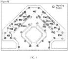
- Fig. 1 is a view showing a map and signaling nodes that is provided to the terminal device according to a preferred embodiment of the present invention.
- one or more signaling node 200 can be installed in the space.
- the present invention is characterized by receiving signals from signaling nodes 200 and determining the user's position from signals received.
- signaling nodes 200 maybe installed in great number in tight spaces such as the area 950, 954, 956, and 960 or installed in relatively small number in big spaces such as the area 961 and 962.
- One or more signaling nodes 200 that were installed as describe above, transmit repeated signals with the same intensity when they receive a location request signal.
- Signals transmitted by a signaling node 200 can be invisible light, sound wave or RF signals. And, these signals can include ID and location information of the each signaling node.
- the user can determine his or her position when the user receives signals transmitted from one or more signaling nodes 200, by utilizing the received signal strength and the location information of each signaling nodes. This characterizes the basic concept of a node network according to an embodiment of the present invention.
- the portable terminal 100 will receive signals from nodes in the area 957 along with signals from adjacent areas such as 955, 956 and 958.
- the intensity of signals from nodes in the area 957 will be relatively high and the intensity of signals from nodes in the area 955, 956, and 958 will be relatively low, which leads to a clue that the user is in the area 957.
- the user can also determine even more specific position based on the received signal strength and coordinates of signaling nodes through a pre-programmed algorithm with the terminal 100. More detailed description will be described with reference to Fig. 3 below.
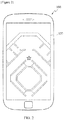
- the current position of the user can now be displayed on the display 120 of the terminal 100 as shown in Fig. 2 .
- Fig. 3 is a block diagram of the terminal 100 according to a preferred embodiment of the present invention.
- the terminal 100 serves the purpose of providing user's position who carries the terminal 100 based on signals transmitted from one or more signaling nodes 200.
- the terminal 100 can include a terminal controller 110, a display 120, a wireless communication unit 130, an invisible light sensor 140, a RF transmitter 150, an RF receiver 160, a terminal timer 170, a sound receiver 180, and an input 190.
- a terminal controller 110 the terminal controller 110
- the terminal 100 serves the purpose of providing user's position who carries the terminal 100 based on signals transmitted from one or more signaling nodes 200.
- the terminal 100 can include a terminal controller 110, a display 120, a wireless communication unit 130, an invisible light sensor 140, a RF transmitter 150, an RF receiver 160, a terminal timer 170, a sound receiver 180, and an input 190.
- a terminal controller 110 controls the terminal's position who carries the terminal 100 based
- the terminal controller 110 serves a function to determine the position of the user carrying a device of the present invention based on received signals transmitted from one or more signaling nodes. Before this procedure is performed, a process is made to transmit a location request signal through the RF transmitter 150 to be received by one or more signaling nodes.
- Signals transmitted from one or more signaling nodes mentioned above include location information of the signaling node that transmitted the signal.
- signals received from one or more signaling nodes can be either invisible light, sound or RF signal. Invisible light signals can be detected by the invisible light sensor 140. Sound wave can be received by the sound receiver 180. RF signal can be received by RF receiver 160. Since all signals from one or more signaling nodes started with the same intensity, the terminal controller 110 can measure the distance between the user and the each signaling nodes from the value of the received signal strength.
- the order of priority for calculation can be light signal, sound wave, and RF signal.
- the order of priority can be different according to the user's policy, it is preferable to keep the order of light, sound, and RF signal since there are differences in characteristics such as diffraction and permeability of the medium.
- invisible light in the following description may include at least one of any infrared rays and ultraviolet rays.
- invisible light can be at least one of many types of lights such as near infrared ray, infrared ray, far infrared ray, near ultraviolet ray, ultraviolet ray, and far ultraviolet rays.
- Invisible light signal emitted from signaling nodes 200 discussed above may carry the location information of the signaling node as well as latitude, longitude, altitude, and ID of the terminal that made a request for location.
- the invisible light signal from a signaling node carries a variety of information. Therefore, the terminal controller 110 can find out from which signaling node the light signal had been emitted, when the invisible light is detected from the invisible light sensor 140. In addition, since the signal strength of the invisible light had a pre-determined strength, a level of decrease in signal strength can be measured by comparing the original signal strength and the received signal strength. Since the decrease in signal strength is proportional to the traveled distance, the distance between the terminal 100 and a signaling node can be determined from the signal strength received by the invisible light sensor 140.
- the terminal controller 110 regards the coordinates A of the signaling node as the user's position, and may draw a circle as the margin of error with the radius being the distance estimated by the received signal strength.
- One tick mark in the graph represents 10M. Therefore, the user's position in the graph is represented as being located somewhere within the circle with the center being at the point A and the radius being 30M.
- Fig. 8 The method of representation of the user's position, when the invisible light sensor 140 detects two invisible light signals, and when the received signal strength of these two signals are same or similar enough to fall within the predetermined error range, is described in Fig. 8 .
- Two signaling nodes are arbitrarily called as points A and B for convenience.
- the user's position is then represented as a circle with A and B as points lying on the opposite ends of the circle and the diameter being the distance between points A and B as shown in Fig. 8 .
- Figs. 9 and 11 are used to illustrate the method when two received signal strength are different.
- the signaling node that has a bigger signal is designated as the point A while the other signaling node as the point B.
- the ratio of the two received signal strength is arbitrarily given as 1:3.
- the nearest possible position of the user from the origin is at the point N (the internal division point of the line-segment AB in the ratio 1:3) lying on a straight line between A and B.
- the farthest possible position of the user is at the point F (the external division point of the line-segment AB in 1:3).
- the user's position can be represented as a circle with points N and F lying the opposite ends, as shown in Fig. 10 .
- the user's position can be represented as a circle with the center being S (- xB / (R 2 - 1), - yB/ (R 2 - 1)) and the radius being D * R / (R 2 - 1).
- the coordinates for N would be (xB/(R+1) , yB/(R+1)) and the coordinates for F would be (-(xB/(R-1)), - (yB/(R-1))).
- a circle to be displayed on the terminal when different received signal strengths are received from two signaling nodes, can be derived from the signal strength ratio and the distance between two nodes by using the Equation 1 below.
- x + xB R 2 ⁇ 1 2 + Y + yB R 2 ⁇ 1 2 Dx R R 2 ⁇ 1 2
- the signaling node with the highest intensity is indicated as A and remaining nodes as B and C.
- an equation of a circle can be obtained through the equation 1 based on the ratio of the received signal strength of A and B.
- Another equation for a circle can be obtained through the equation 1 based on the ratio of the received signal strength of A and C.
- the user's position are narrowed down to tow intersections of two circles denoted as U1 and U2.
- the user's position to be displayed on the terminal is represented as a circle with the center being the closer one to the previous position of the user among U1 and U2, and the radius being the distance between U1 and U2.
- a circle with U1 and U2 as two points at the opposite end is represented as the user's position.
- one of U1 and U2 is located inside the triangle with vertices A, B, and C, and the other outside the triangle.
- an equation for one more circle based on the ratio of the received signal strength between B and C, can be obtained in addition to two circles obtained from the ratio of received signal strength between A and B as well as A and C.
- intersections of the new circle with the other two circles still remain U1 and U2 as shown in Fig. 12 .
- the equation for the circle between B and C was not necessary in paragraph 52.
- the location-tracking method through the terminal 100 has an advantage of not having to synchronize timers of each signaling nodes or the terminal 100. Furthermore, since the present invention relies only on the received signal strength and location of signaling nodes, the terminal 100 in accordance with a preferred embodiment of the present invention does not need the value of original signal strength included in the signal or measure the time with timers.
- Fig. 4 is a block diagram for a signaling node 200 according to a preferred embodiment of the present invention.
- a plurality of the signaling node 200 can be installed and these signaling nodes would transmit signals carrying the location information of each one.
- the signal to be transmitted by these signaling nodes may be in the form of invisible light, sound, and radio waves, each of which may have the same signal strength. Additionally, these signals can be transmitted through different channels to be distinguished from each other.
- the signaling node 200 according to a preferred embodiment of the present invention includes a main body 205 and a sound reflector 260.
- the main body 205 of the signaling node 200 in accordance with a preferred embodiment of the present invention includes a node controller 210, a wireless/wire communication unit 220, a node timer 230, an RF receiver 240, a RF transmitter 245, and a sound transmitter 250.
- a node controller 210 controls the operation of the signaling node 200.
- Node controller 210 controls the overall operation of the signaling node 200.
- Node controller 210 emits invisible light signals through the invisible light transmitter 270 and transmit sound wave signals through a sound transmitter 250.
- the node timer 230 is used to provide the time of transmission of the sound signal, and the RF receiver 240 is used to receive location request signals from the terminal 100.
- the RF transmitter 245 emits RF signals to the terminal 100.
- the RF transmitter 245 can transmit a radio wave signal that carries data including a unique ID, latitude, longitude, altitude, channels, ID of the terminal that sent the location request, time of transmission, channel of invisible light, channel of sound signal, etc..
- the sound transmitter 250 transmits sound wave signals to be received by the terminal 100.
- the sound transmitter 250 as with the RF transmitter 245, can transmit signals that carry data including a unique ID, latitude, longitude, altitude, channel, time of transmission, ID of the terminal that sent a location request signal, etc.
- the invisible light transmitter 270 emits invisible light signals to be detected by the terminal 100.
- the invisible light transmitter 270 according to a preferred embodiment of the present invention, can emit an invisible light signal that carry data with unique ID of the signaling node 200, latitude, longitude, altitude, channel, time of emission, ID of the terminal that requested the location information, etc..
- Sound reflector 260 functions to diffuse the sound waves originating from the sound transmitter 250 in all directions.
- Fig. 5 is a flowchart for a method of providing location information in accordance with a preferred embodiment of the present invention. It is to be understood that repeated descriptions mentioned above and duplicates are omitted in following descriptions.
- a location request signal transmitted at operation S103 may include any data needed for requesting the location information. This data may include various information including the terminal ID.
- operation S105 takes place where signals transmitted from one or more signaling nodes are received.
- signals transmitted from one or more signaling nodes may be in the form of invisible light, sound, and RF signal, which have the same signal strength.
- these signals are sent through different channels.
- channel information of invisible light and sound signals can be included in the RF signal in addition.
- Operation S107 that determines whether a sound signal is received through the sound receiver 180, is performed afterwards. If the sound wave is received, the process advances to operation S109 and calculate the terminal's position on the basis of sound signals. If not, the process goes to operation S111 to determine if invisible light signals are detected.
- the location of the terminal can be traced through, preferably in the order of, invisible light, sound wave, and radio wave.
- Operations S109, S113, and S115 are stages to calculate the location of the terminal that user carries based on invisible sound, light, and RF signals respectively. Since descriptions of these processes were made above, description thereof will not be repeated.
- operation S117 is performed which will output the position data calculated through operation S109, S113 or S115.
- Fig. 6 is a view showing a terminal transmitting a location request signal to signaling nodes and receiving invisible light, sound, and RF signals from signaling nodes in return.
- Fig. 6 illustrates an example where the terminal 100 receives any one among invisible light, sound, and RF signals from the four signaling nodes 200a, 200b, 200c, and 200d.
- the terminal controller 110 measures the received signal strength between the terminal 100 and each signaling nodes (200a, 200b, 200c, and 200d) to calculate the position of the terminal 100.
- the terminal controller 110 in accordance with a preferred embodiment of the present invention calculates the position of the terminal 100 based on at least one out of three media among invisible light, sound, and RF signals which were transmitted upon receiving a location request signal. Since the methods to track the user's location through the above signals were described in detail previously, descriptions for these methods will be omitted.
Landscapes
- Engineering & Computer Science (AREA)
- Physics & Mathematics (AREA)
- Radar, Positioning & Navigation (AREA)
- Remote Sensing (AREA)
- General Physics & Mathematics (AREA)
- Computer Networks & Wireless Communication (AREA)
- Electromagnetism (AREA)
- Position Fixing By Use Of Radio Waves (AREA)
- Mobile Radio Communication Systems (AREA)
- Measurement Of Velocity Or Position Using Acoustic Or Ultrasonic Waves (AREA)
- Optical Communication System (AREA)
Applications Claiming Priority (2)
| Application Number | Priority Date | Filing Date | Title |
|---|---|---|---|
| KR1020150057518A KR101711275B1 (ko) | 2015-04-23 | 2015-04-23 | 위치 정보 제공 장치 및 노드 네트워크 |
| PCT/KR2016/002182 WO2016171387A1 (fr) | 2015-04-23 | 2016-03-04 | Appareil permettant de fournir des informations de position, et nœud de réseau |
Publications (3)
| Publication Number | Publication Date |
|---|---|
| EP3287808A1 true EP3287808A1 (fr) | 2018-02-28 |
| EP3287808A4 EP3287808A4 (fr) | 2018-12-12 |
| EP3287808B1 EP3287808B1 (fr) | 2020-07-01 |
Family
ID=57144079
Family Applications (1)
| Application Number | Title | Priority Date | Filing Date |
|---|---|---|---|
| EP16783321.9A Active EP3287808B1 (fr) | 2015-04-23 | 2016-03-04 | Appareil permettant de fournir des informations de position, et noeud de réseau |
Country Status (6)
| Country | Link |
|---|---|
| US (1) | US10768302B2 (fr) |
| EP (1) | EP3287808B1 (fr) |
| JP (1) | JP6537206B2 (fr) |
| KR (1) | KR101711275B1 (fr) |
| CN (1) | CN107533130B (fr) |
| WO (1) | WO2016171387A1 (fr) |
Cited By (1)
| Publication number | Priority date | Publication date | Assignee | Title |
|---|---|---|---|---|
| US11516625B2 (en) * | 2018-08-21 | 2022-11-29 | Moonshot Health Inc. | Systems and methods for mapping a given environment |
Families Citing this family (4)
| Publication number | Priority date | Publication date | Assignee | Title |
|---|---|---|---|---|
| KR102021300B1 (ko) * | 2017-04-28 | 2019-09-11 | (주)니어스랩 | 위치정보 제공장치 및 이를 이용한 무인비행체의 위치확인 방법 |
| WO2019114925A1 (fr) | 2017-12-11 | 2019-06-20 | Fraunhofer-Gesellschaft zur Förderung der angewandten Forschung e.V. | Procédé de détermination de la position actuelle d'un objet, système de positionnement, moyen de pistage et programme informatique |
| WO2020248179A1 (fr) * | 2019-06-13 | 2020-12-17 | 大连理工大学 | Procédé de détermination de caractéristiques de rotation de sources de lumière en fonction d'un calcul de somme pendant un positionnement de lumière intérieure visible |
| CN112748399B (zh) * | 2020-12-28 | 2024-02-13 | 北京科技大学 | 一种基于多pd接收机的可见光三维定位系统及方法 |
Family Cites Families (37)
| Publication number | Priority date | Publication date | Assignee | Title |
|---|---|---|---|---|
| JPH0744724B2 (ja) * | 1989-07-13 | 1995-05-15 | 日本移動通信株式会社 | 移動局装置および移動通信システム |
| GB2337386B (en) * | 1996-09-09 | 2001-04-04 | Dennis J Dupray | Location of a mobile station |
| JP2005223436A (ja) * | 2004-02-03 | 2005-08-18 | Hitachi Ltd | 携帯端末及び位置情報交換システム |
| KR20050095401A (ko) * | 2004-03-26 | 2005-09-29 | 한석운 | 음파 또는 초음파의 전달시간을 이용한 삼차원 공간위치파악장치 |
| DE102004027292A1 (de) * | 2004-06-04 | 2005-12-29 | Siemens Ag | Vefahren zur Bestimmung von Positionsdaten |
| JP2006300602A (ja) * | 2005-04-18 | 2006-11-02 | Falcon:Kk | 測位データの取得方法、取得装置及び取得システム |
| WO2006116528A2 (fr) * | 2005-04-26 | 2006-11-02 | Rf Code, Inc. | Systemes d'identification par radiofrequence (rfid) et procedes faisant appel a la localisation infrarouge |
| US8265656B2 (en) * | 2005-12-07 | 2012-09-11 | Ekahau Oy | Positioning technique |
| US7576694B2 (en) * | 2006-04-20 | 2009-08-18 | Toshiba America Research, Inc. | Secure wireless user localization scheme using transmission range variation |
| KR100781527B1 (ko) * | 2006-05-22 | 2007-12-03 | 삼성전자주식회사 | 이동 기기의 위치정보를 제공하는 장치 및 방법과 이동기기의 위치정보를 생성하고 인식하는 장치 및 방법 |
| KR101361191B1 (ko) * | 2007-05-11 | 2014-02-10 | 삼성전자주식회사 | 무선 위치측정 시스템 및 그의 고정노드 좌표 결정 방법 |
| CN101210965B (zh) * | 2007-12-21 | 2011-06-29 | 新动力(北京)建筑科技有限公司 | 无线测距的方法、无线测距和定位的方法、设备及系统 |
| JP2009281793A (ja) * | 2008-05-20 | 2009-12-03 | Brother Ind Ltd | 移動局測位システム |
| JP2010010850A (ja) * | 2008-06-25 | 2010-01-14 | Nec Tokin Corp | 無線端末の位置推定システム |
| CN101662401B (zh) * | 2008-08-27 | 2012-06-06 | 联想(北京)有限公司 | 一种链式无线网络的组建方法及网络节点 |
| JP2010087933A (ja) * | 2008-09-30 | 2010-04-15 | Brother Ind Ltd | 移動局測位システム、移動局測位システムに適用可能な移動局および基地局 |
| KR101095017B1 (ko) * | 2008-12-23 | 2011-12-20 | 한국전자통신연구원 | Rf 기반의 실내 위치 추정 방법 및 장치 |
| KR20110012584A (ko) * | 2009-07-31 | 2011-02-09 | 삼성전자주식회사 | 초음파 기반 3차원 위치 추정 장치 및 방법 |
| KR20110035984A (ko) * | 2009-09-30 | 2011-04-06 | 한국전자통신연구원 | 무선 측위 방법 및 장치 |
| JP5712521B2 (ja) * | 2010-07-27 | 2015-05-07 | 富士通株式会社 | 測位装置、測位信号送信装置、測位方法、および測位信号送信方法 |
| US8565783B2 (en) * | 2010-11-24 | 2013-10-22 | Microsoft Corporation | Path progression matching for indoor positioning systems |
| KR101202613B1 (ko) * | 2011-04-04 | 2012-11-19 | 한국과학기술원 | 위치인식 장치와 시스템 및 방법 |
| US8639640B1 (en) * | 2011-06-10 | 2014-01-28 | Google Inc. | Prediction of indoor location using decision trees |
| JP5710438B2 (ja) * | 2011-10-03 | 2015-04-30 | インターナショナル・ビジネス・マシーンズ・コーポレーションInternational Business Machines Corporation | 位置検出装置、位置管理システム、位置検出方法およびプログラム |
| CN102608570B (zh) * | 2012-01-17 | 2014-06-04 | 华中科技大学 | 一种坑道无线传感器节点测距及定位方法 |
| US9264874B2 (en) * | 2012-10-02 | 2016-02-16 | Federico Fraccaroli | Method and apparatus for location based networking sessions |
| US20140111380A1 (en) * | 2012-10-22 | 2014-04-24 | Cambridge Silicon Radio Limited | Method for short-range proximity derivation and tracking |
| KR101303729B1 (ko) * | 2013-03-12 | 2013-09-04 | 임동권 | 음파를 이용한 위치 정보 제공 시스템 |
| US20140274119A1 (en) * | 2013-03-15 | 2014-09-18 | Qualcomm Incorporated | Method and apparatus for indoor positioning based on wireless landmarks |
| WO2014203041A1 (fr) * | 2013-06-20 | 2014-12-24 | Qatar University Qstp-B | Système et procédé de localisation en intérieur par rfid |
| WO2015027118A1 (fr) * | 2013-08-22 | 2015-02-26 | Qualcomm Incorporated | Utilisation d'un signal de référence pour une localisation en intérieur |
| US9810764B2 (en) * | 2013-09-30 | 2017-11-07 | AT&T Intellectual Preoperty I, L.P. | Systems and methods for high precision indoor location tracking |
| US9863773B2 (en) * | 2014-04-29 | 2018-01-09 | Samsung Electronics Co., Ltd. | Indoor global positioning system |
| US10509096B2 (en) * | 2014-05-09 | 2019-12-17 | Microsoft Technology Licensing, Llc | Location error radius determination |
| US20150330795A1 (en) * | 2014-05-15 | 2015-11-19 | Qualcomm Incorporated | Method to Dynamically Adjust Assistance Data for Improved Indoor Positioning Performance |
| US10401470B2 (en) * | 2014-08-12 | 2019-09-03 | Signify Holding B.V. | Method and apparatus for locating of a mobile device |
| EP3186655B1 (fr) * | 2014-08-25 | 2023-03-08 | Lonprox Corporation | Localisation de position intérieure en utilisant des réflecteurs directionnels à balayage retardé |
-
2015
- 2015-04-23 KR KR1020150057518A patent/KR101711275B1/ko active IP Right Grant
-
2016
- 2016-03-04 WO PCT/KR2016/002182 patent/WO2016171387A1/fr active Application Filing
- 2016-03-04 JP JP2017552094A patent/JP6537206B2/ja not_active Expired - Fee Related
- 2016-03-04 EP EP16783321.9A patent/EP3287808B1/fr active Active
- 2016-03-04 US US15/568,527 patent/US10768302B2/en not_active Expired - Fee Related
- 2016-03-04 CN CN201680022116.2A patent/CN107533130B/zh active Active
Cited By (1)
| Publication number | Priority date | Publication date | Assignee | Title |
|---|---|---|---|---|
| US11516625B2 (en) * | 2018-08-21 | 2022-11-29 | Moonshot Health Inc. | Systems and methods for mapping a given environment |
Also Published As
| Publication number | Publication date |
|---|---|
| KR20160126475A (ko) | 2016-11-02 |
| CN107533130A (zh) | 2018-01-02 |
| WO2016171387A1 (fr) | 2016-10-27 |
| US20180113214A1 (en) | 2018-04-26 |
| JP2018515754A (ja) | 2018-06-14 |
| CN107533130B (zh) | 2021-03-12 |
| KR101711275B1 (ko) | 2017-03-02 |
| JP6537206B2 (ja) | 2019-07-03 |
| EP3287808A4 (fr) | 2018-12-12 |
| EP3287808B1 (fr) | 2020-07-01 |
| US10768302B2 (en) | 2020-09-08 |
Similar Documents
| Publication | Publication Date | Title |
|---|---|---|
| EP3287808B1 (fr) | Appareil permettant de fournir des informations de position, et noeud de réseau | |
| EP2149227B1 (fr) | Procédé servant à mesurer un emplacement d'un lecteur d'identification d'une fréquence radio en utilisant une balise électromagnétique | |
| Nakajima et al. | Indoor navigation system for visually impaired people using visible light communication and compensated geomagnetic sensing | |
| KR101049603B1 (ko) | Rfid를 이용한 이동체 실시간 위치 결정 시스템 및 그 방법과, 그를 위한 무선중계장치 설치 방법 | |
| US20170245116A1 (en) | Indoor positioning system and method having improved accuracy | |
| CN108027419A (zh) | 自组织混合室内定位系统 | |
| KR101247964B1 (ko) | 비콘을 이용한 전파식별 리더의 위치 측정 방법 및 그를 위한 전파식별 시스템 | |
| US10009734B2 (en) | Indoor location measurement system and method using radio signal transmitters | |
| CN111164448A (zh) | 在位置确定系统中使用的发送设备 | |
| CN112308998A (zh) | 一种基于蓝牙的室内定位智能巡检系统及方法 | |
| CN109073391A (zh) | 利用来自网状网络的位置辅助的车辆导航系统和方法 | |
| KR101081684B1 (ko) | 긴급구조 시스템 및 위치 검출 방법 | |
| US10412700B2 (en) | Portable-device-locating system that uses room-level motion sensors and RSSI measurements to determine precise room-location | |
| D'Souza et al. | Wireless localisation network for patient tracking | |
| CN109387808A (zh) | 一种定位待测点的方法及装置 | |
| KR100397325B1 (ko) | 지상형 위치추적시스템 | |
| KR100397326B1 (ko) | 위치 추적을 위한 거리 추출 방법 | |
| JP2006118881A (ja) | 位置測位装置および位置測位方法 | |
| ES2925299T3 (es) | Métodos y sistemas de radioguiado en entornos no cooperativos | |
| JP2003149342A (ja) | 衛星測位と光波測位方式を用いた移動体測位方法及び装置 | |
| Moutinho et al. | Indoor Sound Based Localization: Research Questions and First Results | |
| KR20120019999A (ko) | 위치 추적 칩셋 및 위치 추적 칩셋과 단말기의 구동 방법 | |
| US20080319669A1 (en) | System and Device Used to Automatically Determine the Position of an Entity with Respect to Two or More Reference Entities in Real Time | |
| KR20160146382A (ko) | 다수의 신호 송출기 및 신호 탐색기 기반의 위치특정 시스템 및 이를 이용한 위치특정 방법 | |
| KR20010064089A (ko) | 지상형 위치 추적 방법 |
Legal Events
| Date | Code | Title | Description |
|---|---|---|---|
| STAA | Information on the status of an ep patent application or granted ep patent |
Free format text: STATUS: THE INTERNATIONAL PUBLICATION HAS BEEN MADE |
|
| PUAI | Public reference made under article 153(3) epc to a published international application that has entered the european phase |
Free format text: ORIGINAL CODE: 0009012 |
|
| STAA | Information on the status of an ep patent application or granted ep patent |
Free format text: STATUS: REQUEST FOR EXAMINATION WAS MADE |
|
| 17P | Request for examination filed |
Effective date: 20171116 |
|
| AK | Designated contracting states |
Kind code of ref document: A1 Designated state(s): AL AT BE BG CH CY CZ DE DK EE ES FI FR GB GR HR HU IE IS IT LI LT LU LV MC MK MT NL NO PL PT RO RS SE SI SK SM TR |
|
| AX | Request for extension of the european patent |
Extension state: BA ME |
|
| DAV | Request for validation of the european patent (deleted) | ||
| DAX | Request for extension of the european patent (deleted) | ||
| A4 | Supplementary search report drawn up and despatched |
Effective date: 20181113 |
|
| RIC1 | Information provided on ipc code assigned before grant |
Ipc: G01S 17/02 20060101ALI20181107BHEP Ipc: G01S 1/70 20060101ALI20181107BHEP Ipc: G01S 11/04 20060101AFI20181107BHEP Ipc: G01S 5/02 20100101ALI20181107BHEP Ipc: G01S 5/16 20060101ALI20181107BHEP |
|
| RIC1 | Information provided on ipc code assigned before grant |
Ipc: G01S 5/16 20060101ALI20181123BHEP Ipc: G01S 5/02 20100101ALI20181123BHEP Ipc: G01S 11/04 20060101AFI20181123BHEP Ipc: G01S 17/02 20060101ALI20181123BHEP Ipc: G01S 1/70 20060101ALI20181123BHEP |
|
| STAA | Information on the status of an ep patent application or granted ep patent |
Free format text: STATUS: EXAMINATION IS IN PROGRESS |
|
| 17Q | First examination report despatched |
Effective date: 20190806 |
|
| GRAP | Despatch of communication of intention to grant a patent |
Free format text: ORIGINAL CODE: EPIDOSNIGR1 |
|
| STAA | Information on the status of an ep patent application or granted ep patent |
Free format text: STATUS: GRANT OF PATENT IS INTENDED |
|
| INTG | Intention to grant announced |
Effective date: 20200309 |
|
| GRAS | Grant fee paid |
Free format text: ORIGINAL CODE: EPIDOSNIGR3 |
|
| GRAA | (expected) grant |
Free format text: ORIGINAL CODE: 0009210 |
|
| STAA | Information on the status of an ep patent application or granted ep patent |
Free format text: STATUS: THE PATENT HAS BEEN GRANTED |
|
| AK | Designated contracting states |
Kind code of ref document: B1 Designated state(s): AL AT BE BG CH CY CZ DE DK EE ES FI FR GB GR HR HU IE IS IT LI LT LU LV MC MK MT NL NO PL PT RO RS SE SI SK SM TR |
|
| REG | Reference to a national code |
Ref country code: CH Ref legal event code: EP Ref country code: AT Ref legal event code: REF Ref document number: 1286674 Country of ref document: AT Kind code of ref document: T Effective date: 20200715 |
|
| REG | Reference to a national code |
Ref country code: IE Ref legal event code: FG4D |
|
| REG | Reference to a national code |
Ref country code: DE Ref legal event code: R096 Ref document number: 602016039175 Country of ref document: DE |
|
| REG | Reference to a national code |
Ref country code: NL Ref legal event code: FP |
|
| REG | Reference to a national code |
Ref country code: LT Ref legal event code: MG4D |
|
| PG25 | Lapsed in a contracting state [announced via postgrant information from national office to epo] |
Ref country code: BG Free format text: LAPSE BECAUSE OF FAILURE TO SUBMIT A TRANSLATION OF THE DESCRIPTION OR TO PAY THE FEE WITHIN THE PRESCRIBED TIME-LIMIT Effective date: 20201001 |
|
| REG | Reference to a national code |
Ref country code: AT Ref legal event code: MK05 Ref document number: 1286674 Country of ref document: AT Kind code of ref document: T Effective date: 20200701 |
|
| PG25 | Lapsed in a contracting state [announced via postgrant information from national office to epo] |
Ref country code: ES Free format text: LAPSE BECAUSE OF FAILURE TO SUBMIT A TRANSLATION OF THE DESCRIPTION OR TO PAY THE FEE WITHIN THE PRESCRIBED TIME-LIMIT Effective date: 20200701 Ref country code: CZ Free format text: LAPSE BECAUSE OF FAILURE TO SUBMIT A TRANSLATION OF THE DESCRIPTION OR TO PAY THE FEE WITHIN THE PRESCRIBED TIME-LIMIT Effective date: 20200701 Ref country code: SE Free format text: LAPSE BECAUSE OF FAILURE TO SUBMIT A TRANSLATION OF THE DESCRIPTION OR TO PAY THE FEE WITHIN THE PRESCRIBED TIME-LIMIT Effective date: 20200701 Ref country code: HR Free format text: LAPSE BECAUSE OF FAILURE TO SUBMIT A TRANSLATION OF THE DESCRIPTION OR TO PAY THE FEE WITHIN THE PRESCRIBED TIME-LIMIT Effective date: 20200701 Ref country code: LT Free format text: LAPSE BECAUSE OF FAILURE TO SUBMIT A TRANSLATION OF THE DESCRIPTION OR TO PAY THE FEE WITHIN THE PRESCRIBED TIME-LIMIT Effective date: 20200701 Ref country code: FI Free format text: LAPSE BECAUSE OF FAILURE TO SUBMIT A TRANSLATION OF THE DESCRIPTION OR TO PAY THE FEE WITHIN THE PRESCRIBED TIME-LIMIT Effective date: 20200701 Ref country code: PT Free format text: LAPSE BECAUSE OF FAILURE TO SUBMIT A TRANSLATION OF THE DESCRIPTION OR TO PAY THE FEE WITHIN THE PRESCRIBED TIME-LIMIT Effective date: 20201102 Ref country code: AT Free format text: LAPSE BECAUSE OF FAILURE TO SUBMIT A TRANSLATION OF THE DESCRIPTION OR TO PAY THE FEE WITHIN THE PRESCRIBED TIME-LIMIT Effective date: 20200701 Ref country code: GR Free format text: LAPSE BECAUSE OF FAILURE TO SUBMIT A TRANSLATION OF THE DESCRIPTION OR TO PAY THE FEE WITHIN THE PRESCRIBED TIME-LIMIT Effective date: 20201002 Ref country code: NO Free format text: LAPSE BECAUSE OF FAILURE TO SUBMIT A TRANSLATION OF THE DESCRIPTION OR TO PAY THE FEE WITHIN THE PRESCRIBED TIME-LIMIT Effective date: 20201001 |
|
| PG25 | Lapsed in a contracting state [announced via postgrant information from national office to epo] |
Ref country code: PL Free format text: LAPSE BECAUSE OF FAILURE TO SUBMIT A TRANSLATION OF THE DESCRIPTION OR TO PAY THE FEE WITHIN THE PRESCRIBED TIME-LIMIT Effective date: 20200701 Ref country code: RS Free format text: LAPSE BECAUSE OF FAILURE TO SUBMIT A TRANSLATION OF THE DESCRIPTION OR TO PAY THE FEE WITHIN THE PRESCRIBED TIME-LIMIT Effective date: 20200701 Ref country code: LV Free format text: LAPSE BECAUSE OF FAILURE TO SUBMIT A TRANSLATION OF THE DESCRIPTION OR TO PAY THE FEE WITHIN THE PRESCRIBED TIME-LIMIT Effective date: 20200701 Ref country code: IS Free format text: LAPSE BECAUSE OF FAILURE TO SUBMIT A TRANSLATION OF THE DESCRIPTION OR TO PAY THE FEE WITHIN THE PRESCRIBED TIME-LIMIT Effective date: 20201101 |
|
| REG | Reference to a national code |
Ref country code: DE Ref legal event code: R097 Ref document number: 602016039175 Country of ref document: DE |
|
| PG25 | Lapsed in a contracting state [announced via postgrant information from national office to epo] |
Ref country code: IT Free format text: LAPSE BECAUSE OF FAILURE TO SUBMIT A TRANSLATION OF THE DESCRIPTION OR TO PAY THE FEE WITHIN THE PRESCRIBED TIME-LIMIT Effective date: 20200701 Ref country code: EE Free format text: LAPSE BECAUSE OF FAILURE TO SUBMIT A TRANSLATION OF THE DESCRIPTION OR TO PAY THE FEE WITHIN THE PRESCRIBED TIME-LIMIT Effective date: 20200701 Ref country code: SM Free format text: LAPSE BECAUSE OF FAILURE TO SUBMIT A TRANSLATION OF THE DESCRIPTION OR TO PAY THE FEE WITHIN THE PRESCRIBED TIME-LIMIT Effective date: 20200701 Ref country code: DK Free format text: LAPSE BECAUSE OF FAILURE TO SUBMIT A TRANSLATION OF THE DESCRIPTION OR TO PAY THE FEE WITHIN THE PRESCRIBED TIME-LIMIT Effective date: 20200701 Ref country code: RO Free format text: LAPSE BECAUSE OF FAILURE TO SUBMIT A TRANSLATION OF THE DESCRIPTION OR TO PAY THE FEE WITHIN THE PRESCRIBED TIME-LIMIT Effective date: 20200701 |
|
| PGFP | Annual fee paid to national office [announced via postgrant information from national office to epo] |
Ref country code: LU Payment date: 20210326 Year of fee payment: 6 Ref country code: IE Payment date: 20210325 Year of fee payment: 6 Ref country code: FR Payment date: 20210325 Year of fee payment: 6 |
|
| PLBE | No opposition filed within time limit |
Free format text: ORIGINAL CODE: 0009261 |
|
| STAA | Information on the status of an ep patent application or granted ep patent |
Free format text: STATUS: NO OPPOSITION FILED WITHIN TIME LIMIT |
|
| PG25 | Lapsed in a contracting state [announced via postgrant information from national office to epo] |
Ref country code: AL Free format text: LAPSE BECAUSE OF FAILURE TO SUBMIT A TRANSLATION OF THE DESCRIPTION OR TO PAY THE FEE WITHIN THE PRESCRIBED TIME-LIMIT Effective date: 20200701 |
|
| 26N | No opposition filed |
Effective date: 20210406 |
|
| PG25 | Lapsed in a contracting state [announced via postgrant information from national office to epo] |
Ref country code: SK Free format text: LAPSE BECAUSE OF FAILURE TO SUBMIT A TRANSLATION OF THE DESCRIPTION OR TO PAY THE FEE WITHIN THE PRESCRIBED TIME-LIMIT Effective date: 20200701 |
|
| PG25 | Lapsed in a contracting state [announced via postgrant information from national office to epo] |
Ref country code: SI Free format text: LAPSE BECAUSE OF FAILURE TO SUBMIT A TRANSLATION OF THE DESCRIPTION OR TO PAY THE FEE WITHIN THE PRESCRIBED TIME-LIMIT Effective date: 20200701 |
|
| PG25 | Lapsed in a contracting state [announced via postgrant information from national office to epo] |
Ref country code: MC Free format text: LAPSE BECAUSE OF FAILURE TO SUBMIT A TRANSLATION OF THE DESCRIPTION OR TO PAY THE FEE WITHIN THE PRESCRIBED TIME-LIMIT Effective date: 20200701 |
|
| REG | Reference to a national code |
Ref country code: CH Ref legal event code: PL |
|
| REG | Reference to a national code |
Ref country code: BE Ref legal event code: MM Effective date: 20210331 |
|
| PG25 | Lapsed in a contracting state [announced via postgrant information from national office to epo] |
Ref country code: CH Free format text: LAPSE BECAUSE OF NON-PAYMENT OF DUE FEES Effective date: 20210331 Ref country code: LI Free format text: LAPSE BECAUSE OF NON-PAYMENT OF DUE FEES Effective date: 20210331 |
|
| PGFP | Annual fee paid to national office [announced via postgrant information from national office to epo] |
Ref country code: GB Payment date: 20220317 Year of fee payment: 7 Ref country code: DE Payment date: 20220322 Year of fee payment: 7 |
|
| PGFP | Annual fee paid to national office [announced via postgrant information from national office to epo] |
Ref country code: NL Payment date: 20220322 Year of fee payment: 7 |
|
| PG25 | Lapsed in a contracting state [announced via postgrant information from national office to epo] |
Ref country code: BE Free format text: LAPSE BECAUSE OF NON-PAYMENT OF DUE FEES Effective date: 20210331 |
|
| PG25 | Lapsed in a contracting state [announced via postgrant information from national office to epo] |
Ref country code: LU Free format text: LAPSE BECAUSE OF NON-PAYMENT OF DUE FEES Effective date: 20220304 Ref country code: IE Free format text: LAPSE BECAUSE OF NON-PAYMENT OF DUE FEES Effective date: 20220304 Ref country code: FR Free format text: LAPSE BECAUSE OF NON-PAYMENT OF DUE FEES Effective date: 20220331 |
|
| PG25 | Lapsed in a contracting state [announced via postgrant information from national office to epo] |
Ref country code: CY Free format text: LAPSE BECAUSE OF FAILURE TO SUBMIT A TRANSLATION OF THE DESCRIPTION OR TO PAY THE FEE WITHIN THE PRESCRIBED TIME-LIMIT Effective date: 20200701 |
|
| PG25 | Lapsed in a contracting state [announced via postgrant information from national office to epo] |
Ref country code: HU Free format text: LAPSE BECAUSE OF FAILURE TO SUBMIT A TRANSLATION OF THE DESCRIPTION OR TO PAY THE FEE WITHIN THE PRESCRIBED TIME-LIMIT; INVALID AB INITIO Effective date: 20160304 |
|
| REG | Reference to a national code |
Ref country code: DE Ref legal event code: R119 Ref document number: 602016039175 Country of ref document: DE |
|
| REG | Reference to a national code |
Ref country code: NL Ref legal event code: MM Effective date: 20230401 |
|
| GBPC | Gb: european patent ceased through non-payment of renewal fee |
Effective date: 20230304 |
|
| PG25 | Lapsed in a contracting state [announced via postgrant information from national office to epo] |
Ref country code: NL Free format text: LAPSE BECAUSE OF NON-PAYMENT OF DUE FEES Effective date: 20230401 |
|
| PG25 | Lapsed in a contracting state [announced via postgrant information from national office to epo] |
Ref country code: GB Free format text: LAPSE BECAUSE OF NON-PAYMENT OF DUE FEES Effective date: 20230304 |
|
| PG25 | Lapsed in a contracting state [announced via postgrant information from national office to epo] |
Ref country code: GB Free format text: LAPSE BECAUSE OF NON-PAYMENT OF DUE FEES Effective date: 20230304 Ref country code: DE Free format text: LAPSE BECAUSE OF NON-PAYMENT OF DUE FEES Effective date: 20231003 |
|
| PG25 | Lapsed in a contracting state [announced via postgrant information from national office to epo] |
Ref country code: MK Free format text: LAPSE BECAUSE OF FAILURE TO SUBMIT A TRANSLATION OF THE DESCRIPTION OR TO PAY THE FEE WITHIN THE PRESCRIBED TIME-LIMIT Effective date: 20200701 |
|
| PG25 | Lapsed in a contracting state [announced via postgrant information from national office to epo] |
Ref country code: MT Free format text: LAPSE BECAUSE OF FAILURE TO SUBMIT A TRANSLATION OF THE DESCRIPTION OR TO PAY THE FEE WITHIN THE PRESCRIBED TIME-LIMIT Effective date: 20200701 |