EP3287780A1 - Analysis system for analyzing water and wastewater - Google Patents
Analysis system for analyzing water and wastewater Download PDFInfo
- Publication number
- EP3287780A1 EP3287780A1 EP17194930.8A EP17194930A EP3287780A1 EP 3287780 A1 EP3287780 A1 EP 3287780A1 EP 17194930 A EP17194930 A EP 17194930A EP 3287780 A1 EP3287780 A1 EP 3287780A1
- Authority
- EP
- European Patent Office
- Prior art keywords
- analysis
- nitrogen
- reaction vessel
- oxygen
- carrier gas
- Prior art date
- Legal status (The legal status is an assumption and is not a legal conclusion. Google has not performed a legal analysis and makes no representation as to the accuracy of the status listed.)
- Granted
Links
- XLYOFNOQVPJJNP-UHFFFAOYSA-N water Substances O XLYOFNOQVPJJNP-UHFFFAOYSA-N 0.000 title claims abstract description 12
- 239000002351 wastewater Substances 0.000 title claims abstract description 11
- 239000012159 carrier gas Substances 0.000 claims abstract description 16
- 239000000126 substance Substances 0.000 claims abstract description 11
- 230000029087 digestion Effects 0.000 claims abstract description 4
- IJGRMHOSHXDMSA-UHFFFAOYSA-N Atomic nitrogen Chemical compound N#N IJGRMHOSHXDMSA-UHFFFAOYSA-N 0.000 claims description 44
- 229910052757 nitrogen Inorganic materials 0.000 claims description 22
- QVGXLLKOCUKJST-UHFFFAOYSA-N atomic oxygen Chemical compound [O] QVGXLLKOCUKJST-UHFFFAOYSA-N 0.000 claims description 16
- 229910052760 oxygen Inorganic materials 0.000 claims description 16
- 239000001301 oxygen Substances 0.000 claims description 16
- 230000010354 integration Effects 0.000 claims description 11
- 238000001514 detection method Methods 0.000 claims description 10
- 238000012805 post-processing Methods 0.000 claims description 10
- 230000036962 time dependent Effects 0.000 claims description 9
- OAICVXFJPJFONN-UHFFFAOYSA-N Phosphorus Chemical compound [P] OAICVXFJPJFONN-UHFFFAOYSA-N 0.000 claims description 5
- CURLTUGMZLYLDI-UHFFFAOYSA-N Carbon dioxide Chemical compound O=C=O CURLTUGMZLYLDI-UHFFFAOYSA-N 0.000 claims description 4
- 238000010790 dilution Methods 0.000 claims description 4
- 239000012895 dilution Substances 0.000 claims description 4
- 238000011156 evaluation Methods 0.000 claims description 4
- 229910052698 phosphorus Inorganic materials 0.000 claims description 4
- 239000011574 phosphorus Substances 0.000 claims description 4
- UBAZGMLMVVQSCD-UHFFFAOYSA-N carbon dioxide;molecular oxygen Chemical compound O=O.O=C=O UBAZGMLMVVQSCD-UHFFFAOYSA-N 0.000 claims description 3
- 229910002092 carbon dioxide Inorganic materials 0.000 claims description 2
- 239000001569 carbon dioxide Substances 0.000 claims description 2
- 238000002347 injection Methods 0.000 description 42
- 239000007924 injection Substances 0.000 description 42
- 230000006835 compression Effects 0.000 description 7
- 238000007906 compression Methods 0.000 description 7
- 238000005259 measurement Methods 0.000 description 3
- 238000012986 modification Methods 0.000 description 3
- 230000004048 modification Effects 0.000 description 3
- 239000012494 Quartz wool Substances 0.000 description 2
- 239000002253 acid Substances 0.000 description 2
- 238000013461 design Methods 0.000 description 2
- 230000000694 effects Effects 0.000 description 2
- 230000035515 penetration Effects 0.000 description 2
- 229910000831 Steel Inorganic materials 0.000 description 1
- 230000009471 action Effects 0.000 description 1
- 230000001419 dependent effect Effects 0.000 description 1
- 230000027734 detection of oxygen Effects 0.000 description 1
- 238000011161 development Methods 0.000 description 1
- 230000018109 developmental process Effects 0.000 description 1
- 238000012854 evaluation process Methods 0.000 description 1
- 239000007789 gas Substances 0.000 description 1
- 238000000034 method Methods 0.000 description 1
- 239000000203 mixture Substances 0.000 description 1
- 238000012545 processing Methods 0.000 description 1
- 230000004044 response Effects 0.000 description 1
- 239000010959 steel Substances 0.000 description 1
- 230000002123 temporal effect Effects 0.000 description 1
Images


Classifications
-
- G—PHYSICS
- G01—MEASURING; TESTING
- G01N—INVESTIGATING OR ANALYSING MATERIALS BY DETERMINING THEIR CHEMICAL OR PHYSICAL PROPERTIES
- G01N33/00—Investigating or analysing materials by specific methods not covered by groups G01N1/00 - G01N31/00
- G01N33/18—Water
- G01N33/1806—Water biological or chemical oxygen demand (BOD or COD)
-
- B—PERFORMING OPERATIONS; TRANSPORTING
- B01—PHYSICAL OR CHEMICAL PROCESSES OR APPARATUS IN GENERAL
- B01L—CHEMICAL OR PHYSICAL LABORATORY APPARATUS FOR GENERAL USE
- B01L3/00—Containers or dishes for laboratory use, e.g. laboratory glassware; Droppers
- B01L3/50—Containers for the purpose of retaining a material to be analysed, e.g. test tubes
-
- G—PHYSICS
- G01—MEASURING; TESTING
- G01N—INVESTIGATING OR ANALYSING MATERIALS BY DETERMINING THEIR CHEMICAL OR PHYSICAL PROPERTIES
- G01N1/00—Sampling; Preparing specimens for investigation
- G01N1/02—Devices for withdrawing samples
- G01N1/10—Devices for withdrawing samples in the liquid or fluent state
- G01N1/14—Suction devices, e.g. pumps; Ejector devices
-
- G—PHYSICS
- G01—MEASURING; TESTING
- G01N—INVESTIGATING OR ANALYSING MATERIALS BY DETERMINING THEIR CHEMICAL OR PHYSICAL PROPERTIES
- G01N31/00—Investigating or analysing non-biological materials by the use of the chemical methods specified in the subgroup; Apparatus specially adapted for such methods
- G01N31/12—Investigating or analysing non-biological materials by the use of the chemical methods specified in the subgroup; Apparatus specially adapted for such methods using combustion
-
- G—PHYSICS
- G01—MEASURING; TESTING
- G01N—INVESTIGATING OR ANALYSING MATERIALS BY DETERMINING THEIR CHEMICAL OR PHYSICAL PROPERTIES
- G01N33/00—Investigating or analysing materials by specific methods not covered by groups G01N1/00 - G01N31/00
- G01N33/18—Water
- G01N33/1826—Water organic contamination in water
- G01N33/1846—Total carbon analysis
-
- B—PERFORMING OPERATIONS; TRANSPORTING
- B01—PHYSICAL OR CHEMICAL PROCESSES OR APPARATUS IN GENERAL
- B01L—CHEMICAL OR PHYSICAL LABORATORY APPARATUS FOR GENERAL USE
- B01L2200/00—Solutions for specific problems relating to chemical or physical laboratory apparatus
- B01L2200/02—Adapting objects or devices to another
- B01L2200/025—Align devices or objects to ensure defined positions relative to each other
-
- B—PERFORMING OPERATIONS; TRANSPORTING
- B01—PHYSICAL OR CHEMICAL PROCESSES OR APPARATUS IN GENERAL
- B01L—CHEMICAL OR PHYSICAL LABORATORY APPARATUS FOR GENERAL USE
- B01L2200/00—Solutions for specific problems relating to chemical or physical laboratory apparatus
- B01L2200/06—Fluid handling related problems
- B01L2200/0642—Filling fluids into wells by specific techniques
-
- B—PERFORMING OPERATIONS; TRANSPORTING
- B01—PHYSICAL OR CHEMICAL PROCESSES OR APPARATUS IN GENERAL
- B01L—CHEMICAL OR PHYSICAL LABORATORY APPARATUS FOR GENERAL USE
- B01L2200/00—Solutions for specific problems relating to chemical or physical laboratory apparatus
- B01L2200/16—Reagents, handling or storing thereof
-
- B—PERFORMING OPERATIONS; TRANSPORTING
- B01—PHYSICAL OR CHEMICAL PROCESSES OR APPARATUS IN GENERAL
- B01L—CHEMICAL OR PHYSICAL LABORATORY APPARATUS FOR GENERAL USE
- B01L2300/00—Additional constructional details
- B01L2300/06—Auxiliary integrated devices, integrated components
- B01L2300/0672—Integrated piercing tool
-
- B—PERFORMING OPERATIONS; TRANSPORTING
- B01—PHYSICAL OR CHEMICAL PROCESSES OR APPARATUS IN GENERAL
- B01L—CHEMICAL OR PHYSICAL LABORATORY APPARATUS FOR GENERAL USE
- B01L2300/00—Additional constructional details
- B01L2300/08—Geometry, shape and general structure
- B01L2300/0832—Geometry, shape and general structure cylindrical, tube shaped
-
- B—PERFORMING OPERATIONS; TRANSPORTING
- B01—PHYSICAL OR CHEMICAL PROCESSES OR APPARATUS IN GENERAL
- B01L—CHEMICAL OR PHYSICAL LABORATORY APPARATUS FOR GENERAL USE
- B01L2300/00—Additional constructional details
- B01L2300/14—Means for pressure control
-
- B—PERFORMING OPERATIONS; TRANSPORTING
- B01—PHYSICAL OR CHEMICAL PROCESSES OR APPARATUS IN GENERAL
- B01L—CHEMICAL OR PHYSICAL LABORATORY APPARATUS FOR GENERAL USE
- B01L2400/00—Moving or stopping fluids
- B01L2400/04—Moving fluids with specific forces or mechanical means
- B01L2400/0475—Moving fluids with specific forces or mechanical means specific mechanical means and fluid pressure
- B01L2400/0478—Moving fluids with specific forces or mechanical means specific mechanical means and fluid pressure pistons
Definitions
- the invention relates to an analysis arrangement for water and wastewater analysis, comprising an analyzer with a device housing and an injection port for introducing a sample into the device and an injection syringe.
- the invention is based on the object to provide an improved analysis arrangement of this kind, which can deliver in particular reliably accurate and exactly reproducible analysis results.
- the invention initially includes the idea of modifying the associated injection syringe, deviating from conventional hypodermic syringes, in the interest of an optimal and reproducible performance of the injection procedure.
- an outlet opening of the needle is provided, the surface normal coincides with the needle longitudinal axis (or at least parallel to this).
- an automatically acting ejection element is provided for ejecting a predetermined amount of substance in a predetermined injection period.
- the syringe of the proposed arrangement has both features in combination.
- the injection port is connected to a cylindrical reaction vessel for thermal digestion of the substance to be analyzed, and it has guide means for guiding the injection syringe into a predetermined injection position.
- the guide means are designed in accordance with the shape of the injection needle such that the longitudinal axis of the inserted injection needle coincides with the longitudinal axis of the reaction vessel.
- the guide means comprise a cylindrical or conical guide sleeve.
- the guide means on a stop for limiting the depth of penetration of the injection needle into the reaction vessel.
- the ejection element is designed as a lockable compression spring which acts on the piston of the injection syringe.
- the compression spring which may be formed for example as a steel cylinder spring, thus replacing a manual actuation of the syringe.
- the predetermined spring characteristic of the compression spring ensures a precisely reproducible sample output per unit time.
- the realization of this important effect does not necessarily have to a compression spring (as a particularly simple and inexpensive design) done, but can for example also be done by a small linear motor or a hydraulic or pneumatic drive with a predetermined discharge characteristic.
- the invention includes the idea that with the reaction vessel on the input side, a carrier gas supply is connected, which has controllable means for determining the pressure and flow rate of a carrier gas to be supplied to the reaction vessel.
- a carrier gas supply which has controllable means for determining the pressure and flow rate of a carrier gas to be supplied to the reaction vessel.
- the carrier gas supply comprises a first branch (partial flow) for supplying nitrogen and a second branch (partial flow) for supplying oxygen, wherein in the first branch, a first pressure regulator and flow regulator for pressure control or flow control of nitrogen supplied and in second branch a second pressure regulator and flow regulator for pressure control or flow control are provided with the nitrogen to be mixed with oxygen.
- the first and second pressure and flow regulators are designed and tuned such that when mixing the oxygen with the nitrogen, a dilution by a factor of at least 10, especially at least 100 and more particularly of about 1000, is feasible. It is understood that precision flow controllers are to be used with sufficient accuracy to realize such low dilutions.
- this is based on the consideration of permitting a postprocessing or influencing of the specific evaluation mode as a function of certain characteristics of the analysis result.
- the inventors have found that in the determination of relevant components of water or wastewater samples, the concrete sample composition as well as peculiarities of the course of the analysis can significantly affect the waveform of a time-dependent detection signal and that from this the usefulness of a "manual" influencing the evaluation process derived.
- the post-processing device is designed for the manual post-setting of an integration time for integrating the respectively time-dependent detected concentration values.
- COD or COD chemical oxygen demand
- the analyzer 1 comprises a thermal reaction vessel or an oven EB into which a water sample can be injected by means of a syringe MM via an injection port P arranged at the top of the oven and in which this sample is thermally digested.
- the furnace is fed via a check valve RM1, a carrier gas stream, which is composed of air and nitrogen.
- the carrier gas flow is controlled by means of an air pressure regulator KH1, a nitrogen pressure regulator KH2, an air flow regulator KH4 and a nitrogen flow regulator KH5 and filtered by means of a first and second fine filter HQ1, HQ2 on the input side of the furnace.
- the gas stream On the output side of the furnace, the gas stream first passes into a condensate vessel CM1, and the non-condensed fraction then passes through a quartz wool filter HQ3 and an acid trap HS1 before it reaches the oxygen detector B1, which finally outputs an (electrical) measured value to an adjustable evaluation device A, in which in particular an integration time is provided for the integration of a time-dependent detected oxygen detection signal; see below.
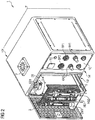
- Fig. 2 shows the analyzer 1 in a perspective view in a state in which the device housing 1 'is partially open and a part of the device components is pulled out of the housing.
- the device housing has essentially the shape of a square prism, and in the front of the device 1A 'is an opening 1B' is provided, which is closed by a hinged on the left side edge of the device front, perforated door 3.
- the device housing 1 'with the door 3 is closed.
- control panel 1C' On the right side of the front panel 1A 'is a control panel 1C', on which a plurality of control and display elements are arranged, including a temperature display / control TC and the air pressure and nitrogen pressure regulators KH1 and KH2 and the associated display elements BP1 and BP1.
- the injection port P On the upper side of the device 1D 'there is the injection port P, whose structure and dimensions correspond to those of the Fig. 1 syringe MM are adapted and communicates inside the device with a corresponding injection valve EB1 of the furnace EB when the furnace is in its normal position of use within the device housing.
- Fig. 3 shows in a sketch in a longitudinal sectional view of the basic structure and the coordinated geometric configuration of the injection syringe MM and the injection port P of the furnace EB of the analysis arrangement.
- the injection port P comprises a guide sleeve P1 which is substantially cylindrical in its longitudinal course and whose diameter and length are matched to the corresponding dimensions of an injection needle MM1 of the injection syringe MM and whose longitudinal axis coincides with a longitudinal axis LA1 of the furnace EB which is cylindrical in its basic form.
- a bore P2 of enlarged diameter Provided on the upper side of the injection port P is a bore P2 of enlarged diameter, the dimensions of which are adapted to those of a needle hub MM2 of the injection syringe and whose lower end face acts as a stop for depth limitation during introduction of the injection syringe. With this stop, a precisely predetermined position of the needle end cut off at right angles to the needle longitudinal axis LA2 of the injection syringe in the oven EB and thus a precisely predetermined injection point is ensured.
- a syringe piston MM4 is mounted longitudinally displaceable, the free end is designed in the usual way for manually mounting a sample.
- a compression spring MM5 is embedded, the upper end is supported against the upper end wall of the syringe reservoir and the lower end acts on the end of the syringe piston MM4.
- the syringe piston MM5 is locked by means of a locking lever MM5.
- the syringe piston MM4 is pressed down by the force of the compression spring MM5 and the sample contained in the syringe reservoir MM3 is injected into the furnace at a predetermined time interval or at a predetermined discharge speed.
- This discharge of the predetermined amount of sample at exactly predetermined speed or in a precisely defined time interval is as important for reproducible analysis results as the exact injection position and direction, which are ensured by the special design of the injection needle and the injection port.
- Fig. 4a and 4b illustrate the effect of an adjustable integration time of the post-processing device A for processing a time-dependent recorded oxygen measurement signal.
- Fig. 4a shows here three different waveforms with (according to the prior art) fixed set integration time t i . It can be seen that only the integration of the measurement signal S 1 represented by the solid line leads to a correct result, while the set integration time for the measurement signals S 2 and S 3 is obviously too short and essential signal components are not detected. Remedy here in the Fig. 4b shown setting of a longer integration time t i2 , 3 for the signals S 2 and S 3 , which can make the operator of the analysis arrangement in response to the detected waveform at the post-processing device A.
Abstract
Analyseanordnung zur Wasser- und Abwasseranalyse, mit einem zylindrischen Reaktionsgefäß zum thermischen Aufschluss des zu analysierenden Stoffes, wobei mit dem Reaktionsgefäß eingangsseitig eine Trägergaszuführung verbunden ist, die steuerbare Mittel zur Festlegung von Druck und Durchflussmenge eines dem Reaktionsgefäß zuzuführenden Trägergases aufweist.Analysis arrangement for water and wastewater analysis, comprising a cylindrical reaction vessel for thermal digestion of the substance to be analyzed, wherein the input side of the reaction vessel, a carrier gas supply is connected, the controllable means for determining the pressure and flow rate of the reaction vessel to be supplied carrier gas.
Description
Die Erfindung betrifft eine Analyseanordnung zur Wasser- und Abwasseranalyse, die ein Analysegerät mit einem Gerätegehäuse und einem Injektionsport zur Einführung einer Probe in das Gerät sowie eine Injektionsspritze umfasst.The invention relates to an analysis arrangement for water and wastewater analysis, comprising an analyzer with a device housing and an injection port for introducing a sample into the device and an injection syringe.
Derartige Analyseanordnungen sind an sich bekannt und werden auch von der Anmelderin hergestellt und angeboten.Such analysis arrangements are known per se and are also manufactured and offered by the applicant.
Der Erfindung liegt die Aufgabe zu Grunde, eine verbesserte Analyseanordnung dieser Art bereitzustellen, die insbesondere verlässlich genaue und exakt reproduzierbare Analyseergebnisse liefern kann.The invention is based on the object to provide an improved analysis arrangement of this kind, which can deliver in particular reliably accurate and exactly reproducible analysis results.
Diese Aufgabe wird nach einem ersten Aspekt der Erfindung gelöst durch ein Analysegerät mit den Merkmalen des Anspruchs 1. Gemäß einem zweiten, relativ unabhängigen Aspekt der Erfindung wird eine Analyseanordnung mit den Merkmalen des Anspruchs 6 vorgeschlagen. Gemäß einem dritten, relativ unabhängigen Aspekt der Erfindung wird eine Analyseanordnung mit den Merkmalen des Anspruchs 9 bereitgestellt. Zweckmäßige Fortbildungen des Erfindungsgedankens sind Gegenstand der abhängigen Ansprüche.This object is achieved according to a first aspect of the invention by an analysis device having the features of
Die Erfindung schließt zunächst den Gedanken ein, die zugehörige Injektionsspritze, abweichend von herkömmlichen Injektionsspritzen, im Interesse einer optimalen und reproduzierbaren Durchführung des Injektionsvorganges zu modifizieren. Gemäß einer ersten Modifikation ist eine Austrittsöffnung der Nadel vorgesehen, deren Flächennormale mit der Nadel-Längsachse zusammenfällt (oder zumindest parallel zu dieser ist). Gemäß einer zweiten Modifikation ist ein selbsttätig wirkendes Ausstoßelement zum Ausstoßen einer vorbestimmten Stoffmenge in einer vorbestimmten Injektionszeitspanne vorgesehen. Zweckmäßigerweise weist die Injektionsspritze der vorgeschlagenen Anordnung beide Merkmale in Kombination auf.The invention initially includes the idea of modifying the associated injection syringe, deviating from conventional hypodermic syringes, in the interest of an optimal and reproducible performance of the injection procedure. According to a first modification, an outlet opening of the needle is provided, the surface normal coincides with the needle longitudinal axis (or at least parallel to this). According to a second modification, an automatically acting ejection element is provided for ejecting a predetermined amount of substance in a predetermined injection period. Conveniently, the syringe of the proposed arrangement has both features in combination.
In einer Ausführung der Erfindung ist der Injektionsport mit einem zylindrischen Reaktionsgefäß zum thermischen Aufschluss des zu analysierenden Stoffes verbunden, und er weist Führungsmittel zum Führen der Injektionsspritze in eine vorbestimmte Einspritzposition auf. Speziell sind die Führungsmittel in Abstimmung auf die Form der Injektionsnadel derart ausgebildet, dass die Längsachse der eingeführten Injektionsnadel mit der Längsachse des Reaktionsgefäßes zusammenfällt. Insbesondere umfassen die Führungsmittel eine zylindrische oder konische Führungshülse. In einer weiteren Ausgestaltung, die mit der vorgenannten kombiniert sein kann, weisen die Führungsmittel einen Anschlag zur Begrenzung der Tiefe des Eindringens der Injektionsnadel in das Reaktionsgefäß auf.In one embodiment of the invention, the injection port is connected to a cylindrical reaction vessel for thermal digestion of the substance to be analyzed, and it has guide means for guiding the injection syringe into a predetermined injection position. Specifically, the guide means are designed in accordance with the shape of the injection needle such that the longitudinal axis of the inserted injection needle coincides with the longitudinal axis of the reaction vessel. In particular, the guide means comprise a cylindrical or conical guide sleeve. In a further embodiment, which may be combined with the aforementioned, the guide means on a stop for limiting the depth of penetration of the injection needle into the reaction vessel.
In einer weiteren Ausführung der Erfindung ist das Ausstoßelement als verriegelbare Druckfeder ausgebildet, die auf den Kolben der Injektionsspritze wirkt. Die Druckfeder, die beispielsweise als stählerne Zylinderfeder ausgebildet sein kann, ersetzt also eine manuelle Betätigung der Spritze. Anders als bei der manuellen Betätigung, sichert die vorbestimmte Federcharakteristik der Druckfeder einen exakt reproduzierbaren Probenausstoß pro Zeiteinheit. Die Realisierung dieser wichtigen Wirkung muss aber nicht notwendigerweise durch eine Druckfeder (als besonders einfache und kostengünstige Ausführung) erfolgen, sondern kann beispielsweise auch durch einen kleinen Linearmotor oder einen hydraulischen oder pneumatischen Antrieb mit vorbestimmter Ausstoßcharakteristik erfolgen.In a further embodiment of the invention, the ejection element is designed as a lockable compression spring which acts on the piston of the injection syringe. The compression spring, which may be formed for example as a steel cylinder spring, thus replacing a manual actuation of the syringe. Unlike the manual operation, the predetermined spring characteristic of the compression spring ensures a precisely reproducible sample output per unit time. However, the realization of this important effect does not necessarily have to a compression spring (as a particularly simple and inexpensive design) done, but can for example also be done by a small linear motor or a hydraulic or pneumatic drive with a predetermined discharge characteristic.
Gemäß dem zweiten Aspekt schließt die Erfindung den Gedanken ein, dass mit dem Reaktionsgefäß eingangsseitig eine Trägergaszuführung verbunden ist, die steuerbare Mittel zur Festlegung von Druck und Durchflussmenge eines dem Reaktionsgefäß zuzuführenden Trägergases aufweist. Neben einer in ihrer Menge präzise bemessenen und im Ort und der Richtung des Ausstoßens der Probe in das Reaktionsgefäß präzise vorbestimmten Probenzuführung ist für exakte und reproduzierbare Analyseergebnisse auch eine genaue und reproduzierbare Steuerung des Trägergasstromes zum Transport der Probe zu einer Nachweiseinrichtung von großer Bedeutung. Es hat sich gezeigt, dass eine einfache Durchflussbegrenzung, etwa mittels eines Reduzierventils, den Genauigkeitsanforderungen einer für den Laboreinsatz geeigneten Analyseanordnung nicht genügt.According to the second aspect, the invention includes the idea that with the reaction vessel on the input side, a carrier gas supply is connected, which has controllable means for determining the pressure and flow rate of a carrier gas to be supplied to the reaction vessel. In addition to a precisely sized sample in its quantity and precisely predetermined in the location and the direction of ejecting the sample into the reaction vessel, accurate and reproducible control of the carrier gas flow for transporting the sample to a detection device is of great importance for exact and reproducible analysis results. It has been found that a simple flow restriction, for example by means of a reducing valve, does not meet the accuracy requirements of an analysis arrangement suitable for laboratory use.
Insbesondere ist hierzu vorgesehen, dass die Trägergaszuführung einen ersten Zweig (Teilstrom) zur Zuführung von Stickstoff und einen zweiten Zweig (Teilstrom) zur Zuführung von Sauerstoff umfasst, wobei im ersten Zweig ein erster Druckregler und Durchflussregler zur Druckregelung bzw. Durchflussregelung von zugeführtem Stickstoff und im zweiten Zweig ein zweiter Druckregler und Durchflussregler zur Druckregelung bzw. Durchflussregelung von mit dem Stickstoff zu vermischendem Sauerstoff vorgesehen sind. Hierbei sind insbesondere die ersten und zweiten Druck- und Durchflussregler derart ausgebildet und abgestimmt, dass bei der Vermischung des Sauerstoffs mit dem Stickstoff eine Verdünnung um einen Faktor von mindestens 10, speziell mindestens 100 und noch spezieller von etwa 1000, realisierbar ist. Es versteht sich, dass zur Realisierung derart niedriger Verdünnungen mit hinreichender Genauigkeit Präzisionsdurchflussregler einzusetzen sind.In particular, it is provided for this purpose that the carrier gas supply comprises a first branch (partial flow) for supplying nitrogen and a second branch (partial flow) for supplying oxygen, wherein in the first branch, a first pressure regulator and flow regulator for pressure control or flow control of nitrogen supplied and in second branch a second pressure regulator and flow regulator for pressure control or flow control are provided with the nitrogen to be mixed with oxygen. Here, in particular, the first and second pressure and flow regulators are designed and tuned such that when mixing the oxygen with the nitrogen, a dilution by a factor of at least 10, especially at least 100 and more particularly of about 1000, is feasible. It is understood that precision flow controllers are to be used with sufficient accuracy to realize such low dilutions.
Gemäß dem oben erwähnten dritten Aspekt der Erfindung basiert diese auf der Überlegung, in Abhängigkeit von bestimmten Merkmalen des Analyseergebnisses eine Nachbearbeitung bzw. Beeinflussung des konkreten Auswertungsmodus zuzulassen. Die Erfinder haben festgestellt, dass bei der Bestimmung relevanter Bestandteile von Wasser- bzw. Abwasserproben die konkrete Probenzusammensetzung wie auch Eigenheiten des Ablaufs der Analyse die Signalform eines zeitabhängigen Nachweissignals erheblich beeinflussen können und dass sich hieraus die Zweckmäßigkeit einer "manuellen" Beeinflussung des Auswertungsvorganges ableitet.According to the abovementioned third aspect of the invention, this is based on the consideration of permitting a postprocessing or influencing of the specific evaluation mode as a function of certain characteristics of the analysis result. The inventors have found that in the determination of relevant components of water or wastewater samples, the concrete sample composition as well as peculiarities of the course of the analysis can significantly affect the waveform of a time-dependent detection signal and that from this the usefulness of a "manual" influencing the evaluation process derived.
Da speziell der zeitliche Signalverlauf bei zeitabhängig gemessenen Sauerstoff-, Kohlendioxid-, Stickstoff- oder Phosphorkonzentrationen des Wassers oder Abwassers sehr unterschiedlich sind, lassen sich mit einer fest eingestellten Integrationszeit nur bedingt brauchbare und vergleichbare Analyseergebnisse erreichen. Es ist daher bevorzugt vorgesehen, dass die Nachbearbeitungseinrichtung zur manuellen Nach-Einstellung einer Integrationszeit zum Aufintegrieren der jeweils zeitabhängig erfassten Konzentrationswerte ausgebildet ist.Since, in particular, the temporal signal curve for time-dependent measured oxygen, carbon dioxide, nitrogen or phosphorus concentrations of the water or wastewater are very different, can be achieved with a fixed integration time only conditionally useful and comparable analysis results. Therefore, it is preferably provided that the post-processing device is designed for the manual post-setting of an integration time for integrating the respectively time-dependent detected concentration values.
Vorteile und Zweckmäßigkeiten der Erfindung ergeben sich im Übrigen aus der nachfolgenden kurzen Beschreibung eines Ausführungsbeispiels anhand der Figuren. Von diesen zeigen:
-
Fig. 1 eine schematische Darstellung wesentlicher Gerätekomponenten eines Analysegerätes gemäß einem Ausführungsbeispiel, -
Fig. 2 eine perspektivische Darstellung jenes Analysegerätes, -
Fig. 3 eine schematische Längsschnittdarstellung einer Injektionsspritze mit in den Injektionsport eingeführter Injektionsnadel gemäß einer beispielhaften Ausführungsform der Analyseanordnung und -
Fig. 4a und 4b grafische Darstellungen zur Illustration eines Aspekts der Erfindung.
-
Fig. 1 a schematic representation of essential device components of an analysis device according to an embodiment, -
Fig. 2 a perspective view of that analyzer, -
Fig. 3 a schematic longitudinal sectional view of an injection syringe with inserted into the injection port injection needle according to an exemplary embodiment of the analysis device and -
Fig. 4a and 4b Graphs illustrating an aspect of the invention.
Das Analysegerät 1 umfasst ein thermisches Reaktionsgefäß bzw. einen Ofen EB, in den mittels einer Injektionsspritze MM über einen an der Ofen-Oberseite angeordneten Injektionsport P eine Wasserprobe eingespritzt werden kann und in dem diese Probe thermisch aufgeschlossen wird. Dem Ofen wird über ein Rückschlagventil RM1 ein Trägergasstrom zugeführt, welcher aus Luft und Stickstoff zusammengesetzt wird. Der Trägergasstrom wird mittels eines Luft-Druckreglers KH1, eines Stickstoff-Druckreglers KH2, eines Luft-Durchflussreglers KH4 und eines Stickstoff-Durchflussreglers KH5 gesteuert und mittels eines ersten und zweiten Feinfilters HQ1, HQ2 eingangsseitig des Ofens gefiltert. Eingangsseitig des Ofens sind auch eine Luft-Druckanzeige BP1 und eine Stickstoff-Druckanzeige BP2 vorgesehen.The
Ausgangsseitig des Ofens gelangt der Gasstrom zunächst in ein Kondensatgefäß CM1, und der nicht kondensierte Anteil durchläuft anschließend ein Quarzwollefilter HQ3 und eine Säurefalle HS1, bevor er zum Sauerstoffdetektor B1 gelangt, welcher schließlich einen (elektrischen) Messwert an eine einstellbare Auswertungseinrichtung A ausgibt, bei der insbesondere eine Integrationszeit zur Aufintegration eines zeitabhängig erfassten Sauerstoff-Nachweissignals vorgesehen ist; siehe dazu weiter unten.On the output side of the furnace, the gas stream first passes into a condensate vessel CM1, and the non-condensed fraction then passes through a quartz wool filter HQ3 and an acid trap HS1 before it reaches the oxygen detector B1, which finally outputs an (electrical) measured value to an adjustable evaluation device A, in which in particular an integration time is provided for the integration of a time-dependent detected oxygen detection signal; see below.
Ein in seinen Abmessungen an die Öffnung 1B' angepasster Schlitten 5, auf dem der Ofen EB, das Kondensatgefäß CM1, das Quarzwollefilter HQ3 und die Säurefalle HS1 angeordnet sind, ist so weit aus dem Gehäuse herausziehbar, dass die genannten Komponenten frei zugänglich werden. Im zurückgeschobenen Zustand des Schlittens 5 wird das Gerätegehäuse 1' mit der Tür 3 verschlossen.A
Auf der rechten Seite der Gerätefront 1A' befindet sich ein Bedienfeld 1C', auf dem mehrere Bedien- und Anzeigeelemente angeordnet sind, darunter eine Temperaturanzeige /-steuerung TC und die Einstellregler KH1 und KH2 für den Luft- bzw. Stickstoffdruck und die zugehörigen Anzeigeelemente BP1 und BP1.On the right side of the
Auf der Geräteoberseite 1D' befindet sich der Injektionsport P, dessen Aufbau und Abmessungen an diejenigen der in
Im Spritzen-Reservoir MM3 ist ein Spritzenkolben MM4 längsverschieblich gelagert, dessen freies Ende in üblicher Weise zum manuellen Aufziehen einer Probe ausgestaltet ist. Am oberen Ende des Spritzenreservoirs ist in diesem eine Druckfeder MM5 eingebettet, deren oberes Ende sich gegen die obere Stirnwand des Spritzenreservoirs abstützt und deren unteres Ende auf das Ende des Spritzenkolbens MM4 wirkt. Nach dem Aufziehen der Spritze wird mittels eines Verriegelungshebels MM6 der Spritzenkolben mit gespannter Feder MM5 arretiert. Nach Lösen der Verriegelung MM6 wird der Spritzenkolben MM4 durch die Kraft der Druckfeder MM5 nach unten gedrückt und die im Spritzenreservoir MM3 enthaltene Probe in einem vorbestimmten Zeitintervall bzw. mit vorbestimmter Austraggeschwindigkeit in den Ofen eingespritzt.In the syringe reservoir MM3 a syringe piston MM4 is mounted longitudinally displaceable, the free end is designed in the usual way for manually mounting a sample. At the upper end of the syringe reservoir in this a compression spring MM5 is embedded, the upper end is supported against the upper end wall of the syringe reservoir and the lower end acts on the end of the syringe piston MM4. After mounting the syringe, the syringe piston MM5 is locked by means of a locking lever MM5. After releasing the lock MM6, the syringe piston MM4 is pressed down by the force of the compression spring MM5 and the sample contained in the syringe reservoir MM3 is injected into the furnace at a predetermined time interval or at a predetermined discharge speed.
Dieser Austrag der vorbestimmten Probenmenge mit exakt vorbestimmter Geschwindigkeit bzw. in einem exakt definierten Zeitintervall ist für reproduzierbare Analyseergebnisse ebenso wichtig wie die exakte Einspritzposition- und Richtung, die durch die spezielle Gestaltung der Injektionsnadel und des Injektionsports gesichert werden.This discharge of the predetermined amount of sample at exactly predetermined speed or in a precisely defined time interval is as important for reproducible analysis results as the exact injection position and direction, which are ensured by the special design of the injection needle and the injection port.
Die Ausführung der Erfindung ist nicht auf dieses Beispiel beschränkt, sondern ebenso in einer Vielzahl von Abwandlungen möglich, die im Rahmen fachgemäßen Handelns liegen.The embodiment of the invention is not limited to this example, but also in a variety of modifications possible, which are within the scope of professional action.
-
1. Analyseanordnung zur Wasser- und Abwasseranalyse, umfassend ein Analysegerät mit
einem Gerätegehäuse, welches Gerätekomponenten aufnimmt und welches an einer Gehäusefläche eine als Injektionsport ausgebildete Eintragöffnung zum Eintragen eines zu analysierenden Stoffes in eine Gerätekomponente bei geschlossenem Gerätegehäuse hat, und
eine Injektionsspritze, welche eine Austrittsöffnung der Injektionsnadel hat, deren Flächennormale mit der Längsachse zusammenfällt, und/oder welche ein selbsttätig wirkendes Ausstoßelement zum Ausstoßen einer vorbestimmten Stoffmenge in einer vorbestimmten Injektionszeitspanne aufweist.1. analysis arrangement for water and wastewater analysis, comprising an analyzer with
a device housing which accommodates device components and which has on a housing surface formed as an injection port entry port for entering a substance to be analyzed in a device component with the device housing closed, and
an injection syringe which has an outlet opening of the injection needle whose surface normal coincides with the longitudinal axis, and / or which has an automatically acting ejection element for ejecting a predetermined amount of substance in a predetermined injection period. -
2. Analyseanordnung nach Aspekt 1, wobei der Injektionsport mit einem zylindrischen Reaktionsgefäß zum thermischen Aufschluss des zu analysierenden Stoffes verbunden ist und Führungsmittel zum Führen der Injektionsspritze in eine vorbestimmte Einspritzposition aufweist.2. analysis arrangement according to
aspect 1, wherein the injection port is connected to a cylindrical reaction vessel for the thermal digestion of the substance to be analyzed and having guide means for guiding the injection syringe in a predetermined injection position. -
3. Analyseanordnung nach Aspekt 2, wobei die Führungsmittel in Abstimmung auf die Form der Injektionsnadel derart ausgebildet sind, dass die Längsachse der eingeführten Injektionsnadel mit der Längsachse des Reaktionsgefäßes zusammenfällt, insbesondere eine zylindrische oder konische Führungshülse aufweisen.3. analysis arrangement according to
aspect 2, wherein the guide means are designed in accordance with the shape of the injection needle such that the longitudinal axis of the inserted injection needle coincides with the longitudinal axis of the reaction vessel, in particular have a cylindrical or conical guide sleeve. -
4. Analyseanordnung nach Aspekt 3, wobei die Führungsmittel einen Anschlag zur Begrenzung der Tiefe des Eindringens der Injektionsnadel in das Reaktionsgefäß aufweisen.4. analysis arrangement according to
aspect 3, wherein the guide means comprise a stop for limiting the depth of penetration of the injection needle into the reaction vessel. - 5. Analyseanordnung nach einem der vorstehenden Aspekte, wobei das Ausstoßelement als verriegelbare Druckfeder ausgebildet ist, die auf den Kolben der Injektionsspritze wirkt.5. analysis arrangement according to one of the preceding aspects, wherein the ejection element is designed as a lockable compression spring which acts on the piston of the injection syringe.
- 6. Analyseanordnung zur Wasser- und Abwasseranalyse, insbesondere nach einem der Aspekte 2 - 5, wobei mit dem Reaktionsgefäß eingangsseitig eine Trägergaszuführung verbunden ist, die steuerbare Mittel zur Festlegung von Druck und Durchflussmenge eines dem Reaktionsgefäß zuzuführenden Trägergases aufweist.6. Analysis arrangement for water and wastewater analysis, in particular according to one of aspects 2-5, wherein the input side of the reaction vessel, a carrier gas supply is connected, the controllable means for determining Pressure and flow rate of the reaction vessel to be supplied to a carrier gas.
- 7. Analyseanordnung nach Aspekt 6, wobei die Trägergaszuführung einen ersten Zweig zur Zuführung von Stickstoff und einen zweiten Zweig zur Zuführung von Sauerstoff umfasst, wobei im ersten Zweig ein erster Druckregler und Durchflussregler zur Druckregelung bzw. Durchflussregelung von zugeführtem Stickstoff und im zweiten Zweig ein zweiter Druckregler und Durchflussregler zur Druckregelung bzw. Durchflussregelung von mit dem Stickstoff zu vermischendem Sauerstoff vorgesehen sind.7. analysis arrangement according to aspect 6, wherein the carrier gas supply comprises a first branch for supplying nitrogen and a second branch for supplying oxygen, wherein in the first branch, a first pressure regulator and flow regulator for pressure control or flow control of nitrogen supplied and in the second branch a second Pressure regulators and flow regulators are provided for pressure regulation or flow control of nitrogen to be mixed with the oxygen.
- 8. Analyseanordnung nach Aspekt 7, wobei die ersten und zweiten Druck- und Durchflussregler derart ausgebildet und abgestimmt sind, dass bei der Vermischung des Sauerstoffs mit dem Stickstoff eine Verdünnung um einen Faktor von mindestens 10, speziell mindestens 100 und noch spezieller von etwa 1000, realisierbar ist.8. Analysis arrangement according to aspect 7, wherein the first and second pressure and flow regulators are designed and tuned such that when the oxygen is mixed with the nitrogen, a dilution by a factor of at least 10, especially at least 100 and more particularly about 1000, is feasible.
- 9. Analyseanordnung zur Wasser- und Abwasseranalyse, insbesondere nach einem der vorstehenden Ansprüche, welche weiter eine Nachweis- und Auswertungseinrichtung zum Nachweis eines vorbestimmten Bestandteils des zu analysierenden Stoffes und eine einstellbare Nachbearbeitungseinrichtung zur manuell gesteuerten Nachbearbeitung des Nachweisergebnisses aufweist.9. analysis arrangement for water and wastewater analysis, in particular according to one of the preceding claims, which further comprises a detection and evaluation device for detecting a predetermined component of the substance to be analyzed and an adjustable post-processing device for manually controlled post-processing of the detection result.
- 10. Analyseanordnung nach Aspekt 9, wobei die Nachweiseinrichtung einen Sauerstoff- und/oder einen Kohlendioxid- und/oder einen Stickstoff- und/oder einen Phosphor-Detektor zum zeitabhängigen Nachweis der Sauerstoff-, Kohlendioxid-, Stickstoff- bzw. Phosphorkonzentration in einem das Reaktionsgefäß verlassenden Trägergasstrom aufweist und die Nachbearbeitungseinrichtung zur manuellen Nach-Einstellung einer Integrationszeit zum Aufintegrieren der jeweils zeitabhängig erfassten Konzentrationswerte ausgebildet ist.10. Analysis arrangement according to aspect 9, wherein the detection means an oxygen and / or a carbon dioxide and / or a nitrogen and / or a phosphorus detector for the time-dependent detection of oxygen, carbon dioxide, nitrogen or phosphorus concentration in a the Carrier gas stream leaving reaction vessel and the post-processing device is designed for manual post-setting of an integration time for integrating the respectively time-dependent detected concentration values.
Claims (5)
Applications Claiming Priority (3)
| Application Number | Priority Date | Filing Date | Title |
|---|---|---|---|
| DE102014118138.7A DE102014118138A1 (en) | 2014-12-08 | 2014-12-08 | Analysis arrangement for water and wastewater analysis |
| PCT/DE2015/100519 WO2016091252A2 (en) | 2014-12-08 | 2015-12-08 | Analysis system for analyzing water and wastewater |
| EP15834790.6A EP3230731B1 (en) | 2014-12-08 | 2015-12-08 | Analysis system for analyzing water and wastewater |
Related Parent Applications (2)
| Application Number | Title | Priority Date | Filing Date |
|---|---|---|---|
| EP15834790.6A Division EP3230731B1 (en) | 2014-12-08 | 2015-12-08 | Analysis system for analyzing water and wastewater |
| EP15834790.6A Division-Into EP3230731B1 (en) | 2014-12-08 | 2015-12-08 | Analysis system for analyzing water and wastewater |
Publications (2)
| Publication Number | Publication Date |
|---|---|
| EP3287780A1 true EP3287780A1 (en) | 2018-02-28 |
| EP3287780B1 EP3287780B1 (en) | 2020-11-04 |
Family
ID=55398142
Family Applications (2)
| Application Number | Title | Priority Date | Filing Date |
|---|---|---|---|
| EP15834790.6A Active EP3230731B1 (en) | 2014-12-08 | 2015-12-08 | Analysis system for analyzing water and wastewater |
| EP17194930.8A Active EP3287780B1 (en) | 2014-12-08 | 2015-12-08 | Analysis system for analyzing water and wastewater |
Family Applications Before (1)
| Application Number | Title | Priority Date | Filing Date |
|---|---|---|---|
| EP15834790.6A Active EP3230731B1 (en) | 2014-12-08 | 2015-12-08 | Analysis system for analyzing water and wastewater |
Country Status (10)
| Country | Link |
|---|---|
| US (1) | US20170343523A1 (en) |
| EP (2) | EP3230731B1 (en) |
| CN (1) | CN107209161B (en) |
| DE (1) | DE102014118138A1 (en) |
| DK (2) | DK3287780T3 (en) |
| ES (2) | ES2833823T3 (en) |
| HU (1) | HUE045901T2 (en) |
| PL (1) | PL3230731T3 (en) |
| RU (1) | RU2017123239A (en) |
| WO (1) | WO2016091252A2 (en) |
Families Citing this family (6)
| Publication number | Priority date | Publication date | Assignee | Title |
|---|---|---|---|---|
| DE102015118586A1 (en) | 2015-10-30 | 2017-05-04 | Lar Process Analysers Ag | sample dilution |
| DE102018105611A1 (en) * | 2018-03-12 | 2019-09-12 | Lar Process Analysers Ag | Measuring arrangement and measuring method for determining an ingredient or quality parameter of water or wastewater |
| CN108313496A (en) * | 2018-04-16 | 2018-07-24 | 安徽省贝斯泰检测科技有限公司 | A kind of device and its application method for Sewage Environment detection storage |
| CN110665560B (en) * | 2019-10-14 | 2022-05-06 | 黄河水利委员会黄河水利科学研究院 | Agricultural non-point source nitrogen and phosphorus pollutant dynamic monitoring test equipment |
| WO2022042857A1 (en) * | 2020-08-28 | 2022-03-03 | HORIBA Tocadero GmbH | Industrial water analysis device and support therefor |
| CN117804873A (en) * | 2024-02-28 | 2024-04-02 | 深圳市瑞盛环保科技有限公司 | Industrial wastewater component selective inspection device for chlorine dissolution treatment system |
Citations (4)
| Publication number | Priority date | Publication date | Assignee | Title |
|---|---|---|---|---|
| US3560156A (en) * | 1965-05-03 | 1971-02-02 | Dow Chemical Co | Determining the oxygen demand of combustible materials in aqueous dispersions |
| DE2261456A1 (en) * | 1972-12-15 | 1974-07-11 | Bayer Ag | PYROLYTIC ANALYSIS OF LIQUIDS |
| US4074973A (en) * | 1975-02-08 | 1978-02-21 | Toray Industries, Inc. | Method and apparatus for determining total oxygen demand of combustible materials in aqueous dispersion |
| EP2662690A1 (en) * | 2011-01-06 | 2013-11-13 | Shimadzu Corporation | Measurement device for total organic carbon |
Family Cites Families (38)
| Publication number | Priority date | Publication date | Assignee | Title |
|---|---|---|---|---|
| GB913473A (en) * | 1960-03-07 | 1962-12-19 | Paul Hersch | Electrode assembly for oxygen analysis |
| US3296435A (en) * | 1964-07-06 | 1967-01-03 | Dow Chemical Co | Method and apparatus for determining the total carbon content of aqueous systems |
| US3567386A (en) * | 1969-02-03 | 1971-03-02 | Dow Chemical Co | Method and apparatus for determining the oxygen demand of oxidizable materials |
| US3567385A (en) * | 1969-02-03 | 1971-03-02 | Dow Chemical Co | Method and apparatus for determining the oxygen demand of oxidizable materials |
| US3854877A (en) * | 1972-08-07 | 1974-12-17 | Dow Chemical Co | Combination tod-tc analysis method |
| US3909202A (en) * | 1972-12-15 | 1975-09-30 | Bayer Ag | Apparatus for analysis of liquids |
| US3960498A (en) * | 1974-08-01 | 1976-06-01 | Instrumentation Laboratory, Inc. | Electrochemical analysis system |
| CA1112474A (en) * | 1978-09-18 | 1981-11-17 | Guy Belanger | Apparatus for the detection and the measurement of hydrogen concentration in a liquid |
| US4228922A (en) * | 1978-10-23 | 1980-10-21 | Ryuzo Takeshita | Apparatus for injecting a desired volume of liquid in liquid and gas-liquid chromatography |
| US4344918A (en) * | 1980-03-05 | 1982-08-17 | Xertex Corporation | Determination of total carbon in liquid samples |
| US6537827B1 (en) * | 1990-04-02 | 2003-03-25 | Janusz B. Pawliszyn | Method and device for solid phase microextraction and desorption |
| GB9203642D0 (en) * | 1992-02-19 | 1992-04-08 | Fluid Dynamics Sales Ltd | Carbon analyser |
| JP2541418B2 (en) * | 1992-03-26 | 1996-10-09 | 株式会社島津製作所 | POC measuring device |
| JPH08501393A (en) * | 1992-09-14 | 1996-02-13 | ローズマウント アナリティカル インコーポレイテッド | Apparatus and method for measuring nitrogen content in a water-containing system |
| DE4437120C2 (en) * | 1994-10-05 | 1998-02-12 | Ufz Leipzighalle Gmbh | Method and device for on-line coupled deuterium determination |
| WO1998022817A1 (en) * | 1996-11-18 | 1998-05-28 | Tekmar Company | Liquid sample carbon analyzer |
| DE29924834U1 (en) * | 1999-01-21 | 2005-12-29 | Lar Analytik & Umweltmesstechnik Gmbh | Waste water sample incinerator for measurement of total organic carbon has ball swivel lock with long service life for sample admission |
| US6257076B1 (en) * | 1999-01-26 | 2001-07-10 | Merlin Instrument Company | Sample injector with plunger release for chemical analysis systems |
| KR100414784B1 (en) * | 2000-01-18 | 2004-01-13 | (주)바이오니아 | Automatic Water Toxicity Measuring Apparatus |
| GB2365122B (en) * | 2000-05-31 | 2004-05-05 | Abb Instrumentation Ltd | Analysis device |
| DE10132390B4 (en) * | 2001-07-06 | 2013-02-21 | Dimatec Analysentechnik Gmbh | Apparatus and method for analyzing organic substances of pure or ultrapure water |
| US6830730B2 (en) * | 2001-09-11 | 2004-12-14 | Spectrolanalytical Instruments | Method and apparatus for the on-stream analysis of total sulfur and/or nitrogen in petroleum products |
| UA76500C2 (en) * | 2001-09-24 | 2006-08-15 | Becton Dickinson Co | Disposable syringe |
| JP3547421B2 (en) * | 2001-12-04 | 2004-07-28 | 誠心エンジニアリング株式会社 | Measurement device for components contained in sample water |
| US7452507B2 (en) * | 2002-08-02 | 2008-11-18 | Sandia Corporation | Portable apparatus for separating sample and detecting target analytes |
| US6666100B1 (en) * | 2002-12-16 | 2003-12-23 | Merlin Instrument Company | Sample injector with interface-control lever |
| DE10360445A1 (en) * | 2003-12-22 | 2005-07-28 | Lar Analytik & Umweltmesstechnik Gmbh | Method and arrangement for the determination of water constituents |
| NL1026878C2 (en) * | 2004-08-19 | 2006-02-21 | Thermo Euroglas B V | Analyzer and method for analyzing a sample, as well as an injection assembly for use with such an analyzer. |
| CA2607894A1 (en) * | 2005-05-16 | 2006-11-23 | Gary S. Wagner | Radiopharmaceutical pigs and portable powered injectors |
| KR20080042076A (en) * | 2005-08-11 | 2008-05-14 | 아쿠아 다이아그노스틱 피티와이 엘티디 | Water analysis using a photoelectrochemical method |
| CN200993616Y (en) * | 2006-12-15 | 2007-12-19 | 邦拓生物科技股份有限公司 | Sampling joint |
| GB2445189B (en) * | 2006-12-29 | 2008-12-10 | Thermo Fisher Scientific Inc | Combustion analysis apparatus and method |
| US8703071B2 (en) * | 2007-10-10 | 2014-04-22 | Etp Mass Spectrometry Pty Ltd | Syringe system |
| DE102008013754A1 (en) * | 2008-03-12 | 2009-09-17 | Lar Process Analysers Ag | Measuring method and measuring arrangement for determining the content of a chemical element or other water quality parameter in fresh or waste water |
| US8412310B2 (en) * | 2009-09-18 | 2013-04-02 | United Medical Innovations, Inc. | Locking syringe with integrated bias member |
| EP2563430A2 (en) * | 2010-04-30 | 2013-03-06 | Bayer Pharma Aktiengesellschaft | Displacement syringe |
| US8394006B2 (en) * | 2010-11-19 | 2013-03-12 | Kensey Nash Corporation | Centrifuge |
| WO2013027747A1 (en) * | 2011-08-22 | 2013-02-28 | 株式会社日立ハイテクノロジーズ | Plug application and removal device and sample processing device |
-
2014
- 2014-12-08 DE DE102014118138.7A patent/DE102014118138A1/en not_active Ceased
-
2015
- 2015-12-08 DK DK17194930.8T patent/DK3287780T3/en active
- 2015-12-08 HU HUE15834790A patent/HUE045901T2/en unknown
- 2015-12-08 ES ES17194930T patent/ES2833823T3/en active Active
- 2015-12-08 PL PL15834790T patent/PL3230731T3/en unknown
- 2015-12-08 CN CN201580074524.8A patent/CN107209161B/en active Active
- 2015-12-08 EP EP15834790.6A patent/EP3230731B1/en active Active
- 2015-12-08 WO PCT/DE2015/100519 patent/WO2016091252A2/en active Application Filing
- 2015-12-08 DK DK15834790.6T patent/DK3230731T3/en active
- 2015-12-08 US US15/534,275 patent/US20170343523A1/en not_active Abandoned
- 2015-12-08 ES ES15834790T patent/ES2747847T3/en active Active
- 2015-12-08 RU RU2017123239A patent/RU2017123239A/en not_active Application Discontinuation
- 2015-12-08 EP EP17194930.8A patent/EP3287780B1/en active Active
Patent Citations (4)
| Publication number | Priority date | Publication date | Assignee | Title |
|---|---|---|---|---|
| US3560156A (en) * | 1965-05-03 | 1971-02-02 | Dow Chemical Co | Determining the oxygen demand of combustible materials in aqueous dispersions |
| DE2261456A1 (en) * | 1972-12-15 | 1974-07-11 | Bayer Ag | PYROLYTIC ANALYSIS OF LIQUIDS |
| US4074973A (en) * | 1975-02-08 | 1978-02-21 | Toray Industries, Inc. | Method and apparatus for determining total oxygen demand of combustible materials in aqueous dispersion |
| EP2662690A1 (en) * | 2011-01-06 | 2013-11-13 | Shimadzu Corporation | Measurement device for total organic carbon |
Also Published As
| Publication number | Publication date |
|---|---|
| WO2016091252A2 (en) | 2016-06-16 |
| DE102014118138A1 (en) | 2016-06-09 |
| DK3287780T3 (en) | 2021-02-01 |
| PL3230731T3 (en) | 2020-04-30 |
| EP3287780B1 (en) | 2020-11-04 |
| EP3230731B1 (en) | 2019-08-07 |
| EP3230731A2 (en) | 2017-10-18 |
| RU2017123239A3 (en) | 2019-01-10 |
| HUE045901T2 (en) | 2020-01-28 |
| ES2747847T3 (en) | 2020-03-11 |
| DK3230731T3 (en) | 2019-10-14 |
| CN107209161B (en) | 2019-12-31 |
| WO2016091252A3 (en) | 2016-09-15 |
| ES2833823T3 (en) | 2021-06-15 |
| US20170343523A1 (en) | 2017-11-30 |
| RU2017123239A (en) | 2019-01-10 |
| CN107209161A (en) | 2017-09-26 |
Similar Documents
| Publication | Publication Date | Title |
|---|---|---|
| EP3287780B1 (en) | Analysis system for analyzing water and wastewater | |
| WO2007112876A2 (en) | Method and device for the analysis of isotope ratios | |
| CH465271A (en) | Column closure for column chromatograph | |
| EP1984729A1 (en) | Method and device for withdrawing a volume of liquid by suction, in particular for collecting a sample for analysis by means of a liquid chromatography device | |
| DE2629048A1 (en) | CHROMATOGRAPH | |
| DE1190697B (en) | Dosing devices for gas analyzers | |
| DE2540969A1 (en) | AUTOMATIC SAMPLE PREPARATION DEVICE | |
| DE2627255C3 (en) | Method and device for generating and transferring a gaseous test sample | |
| EP3374012B1 (en) | Ventilator | |
| AT520515B1 (en) | Device for detecting the quality of a liquid in a supply pipe | |
| DE3302158A1 (en) | Lancing cannula arrangement for introducing a carrier gas into a sample container | |
| DE2447508A1 (en) | METHOD OF INTRODUCING A LIQUID SAMPLE INTO THE FLUID FLOW FLOW IN A HIGH PRESSURE LIQUID CHROMATOGRAPHY SYSTEM AND DEVICE FOR CARRYING OUT THE METHOD | |
| EP3913365B1 (en) | Sample dilution | |
| DE102022101886A1 (en) | Method and device for calibrating a gas detection device | |
| DE2127041A1 (en) | Method and device for Be mood of trace elements in solid samples by means of optical emission Spek trometne | |
| DE102011086942A1 (en) | Method for calibrating and / or adjusting an analyzer for chemical substances in liquids, in particular in aqueous solutions | |
| EP3149434B1 (en) | Analysis device for analyzing water and wastewater | |
| DE2613256A1 (en) | GAIN CONTROL SYSTEM FOR A PHOTO MULTIPLE TUBE | |
| EP2364441A1 (en) | Gas chromatograph comprising a controllable switching device | |
| DE2910101C2 (en) | ||
| DE102008058068A1 (en) | Apparatus and a method for providing a predetermined concentration of at least one component in a liquid medium | |
| DE1619922A1 (en) | Method and device for concentrating and collecting a mixture sample | |
| EP2539693A1 (en) | Method for determining carbon in cast iron | |
| DE102008013754A1 (en) | Measuring method and measuring arrangement for determining the content of a chemical element or other water quality parameter in fresh or waste water | |
| WO2015140343A1 (en) | Calibrating unit for an exhaust-gas measuring device |
Legal Events
| Date | Code | Title | Description |
|---|---|---|---|
| PUAI | Public reference made under article 153(3) epc to a published international application that has entered the european phase |
Free format text: ORIGINAL CODE: 0009012 |
|
| STAA | Information on the status of an ep patent application or granted ep patent |
Free format text: STATUS: THE APPLICATION HAS BEEN PUBLISHED |
|
| AC | Divisional application: reference to earlier application |
Ref document number: 3230731 Country of ref document: EP Kind code of ref document: P |
|
| AK | Designated contracting states |
Kind code of ref document: A1 Designated state(s): AL AT BE BG CH CY CZ DE DK EE ES FI FR GB GR HR HU IE IS IT LI LT LU LV MC MK MT NL NO PL PT RO RS SE SI SK SM TR |
|
| STAA | Information on the status of an ep patent application or granted ep patent |
Free format text: STATUS: REQUEST FOR EXAMINATION WAS MADE |
|
| 17P | Request for examination filed |
Effective date: 20180621 |
|
| RBV | Designated contracting states (corrected) |
Designated state(s): AL AT BE BG CH CY CZ DE DK EE ES FI FR GB GR HR HU IE IS IT LI LT LU LV MC MK MT NL NO PL PT RO RS SE SI SK SM TR |
|
| STAA | Information on the status of an ep patent application or granted ep patent |
Free format text: STATUS: EXAMINATION IS IN PROGRESS |
|
| 17Q | First examination report despatched |
Effective date: 20191004 |
|
| GRAP | Despatch of communication of intention to grant a patent |
Free format text: ORIGINAL CODE: EPIDOSNIGR1 |
|
| STAA | Information on the status of an ep patent application or granted ep patent |
Free format text: STATUS: GRANT OF PATENT IS INTENDED |
|
| INTG | Intention to grant announced |
Effective date: 20200708 |
|
| GRAS | Grant fee paid |
Free format text: ORIGINAL CODE: EPIDOSNIGR3 |
|
| GRAA | (expected) grant |
Free format text: ORIGINAL CODE: 0009210 |
|
| STAA | Information on the status of an ep patent application or granted ep patent |
Free format text: STATUS: THE PATENT HAS BEEN GRANTED |
|
| AC | Divisional application: reference to earlier application |
Ref document number: 3230731 Country of ref document: EP Kind code of ref document: P |
|
| AK | Designated contracting states |
Kind code of ref document: B1 Designated state(s): AL AT BE BG CH CY CZ DE DK EE ES FI FR GB GR HR HU IE IS IT LI LT LU LV MC MK MT NL NO PL PT RO RS SE SI SK SM TR |
|
| REG | Reference to a national code |
Ref country code: GB Ref legal event code: FG4D Free format text: NOT ENGLISH |
|
| REG | Reference to a national code |
Ref country code: CH Ref legal event code: EP |
|
| REG | Reference to a national code |
Ref country code: AT Ref legal event code: REF Ref document number: 1331481 Country of ref document: AT Kind code of ref document: T Effective date: 20201115 |
|
| REG | Reference to a national code |
Ref country code: IE Ref legal event code: FG4D Free format text: LANGUAGE OF EP DOCUMENT: GERMAN |
|
| REG | Reference to a national code |
Ref country code: DE Ref legal event code: R096 Ref document number: 502015013765 Country of ref document: DE |
|
| REG | Reference to a national code |
Ref country code: RO Ref legal event code: EPE |
|
| REG | Reference to a national code |
Ref country code: DK Ref legal event code: T3 Effective date: 20210129 |
|
| REG | Reference to a national code |
Ref country code: NL Ref legal event code: FP |
|
| REG | Reference to a national code |
Ref country code: SE Ref legal event code: TRGR |
|
| PG25 | Lapsed in a contracting state [announced via postgrant information from national office to epo] |
Ref country code: NO Free format text: LAPSE BECAUSE OF FAILURE TO SUBMIT A TRANSLATION OF THE DESCRIPTION OR TO PAY THE FEE WITHIN THE PRESCRIBED TIME-LIMIT Effective date: 20210204 Ref country code: PT Free format text: LAPSE BECAUSE OF FAILURE TO SUBMIT A TRANSLATION OF THE DESCRIPTION OR TO PAY THE FEE WITHIN THE PRESCRIBED TIME-LIMIT Effective date: 20210304 Ref country code: RS Free format text: LAPSE BECAUSE OF FAILURE TO SUBMIT A TRANSLATION OF THE DESCRIPTION OR TO PAY THE FEE WITHIN THE PRESCRIBED TIME-LIMIT Effective date: 20201104 Ref country code: GR Free format text: LAPSE BECAUSE OF FAILURE TO SUBMIT A TRANSLATION OF THE DESCRIPTION OR TO PAY THE FEE WITHIN THE PRESCRIBED TIME-LIMIT Effective date: 20210205 Ref country code: FI Free format text: LAPSE BECAUSE OF FAILURE TO SUBMIT A TRANSLATION OF THE DESCRIPTION OR TO PAY THE FEE WITHIN THE PRESCRIBED TIME-LIMIT Effective date: 20201104 |
|
| PG25 | Lapsed in a contracting state [announced via postgrant information from national office to epo] |
Ref country code: PL Free format text: LAPSE BECAUSE OF FAILURE TO SUBMIT A TRANSLATION OF THE DESCRIPTION OR TO PAY THE FEE WITHIN THE PRESCRIBED TIME-LIMIT Effective date: 20201104 Ref country code: LV Free format text: LAPSE BECAUSE OF FAILURE TO SUBMIT A TRANSLATION OF THE DESCRIPTION OR TO PAY THE FEE WITHIN THE PRESCRIBED TIME-LIMIT Effective date: 20201104 Ref country code: IS Free format text: LAPSE BECAUSE OF FAILURE TO SUBMIT A TRANSLATION OF THE DESCRIPTION OR TO PAY THE FEE WITHIN THE PRESCRIBED TIME-LIMIT Effective date: 20210304 Ref country code: BG Free format text: LAPSE BECAUSE OF FAILURE TO SUBMIT A TRANSLATION OF THE DESCRIPTION OR TO PAY THE FEE WITHIN THE PRESCRIBED TIME-LIMIT Effective date: 20210204 |
|
| REG | Reference to a national code |
Ref country code: LT Ref legal event code: MG9D |
|
| REG | Reference to a national code |
Ref country code: ES Ref legal event code: FG2A Ref document number: 2833823 Country of ref document: ES Kind code of ref document: T3 Effective date: 20210615 |
|
| PG25 | Lapsed in a contracting state [announced via postgrant information from national office to epo] |
Ref country code: HR Free format text: LAPSE BECAUSE OF FAILURE TO SUBMIT A TRANSLATION OF THE DESCRIPTION OR TO PAY THE FEE WITHIN THE PRESCRIBED TIME-LIMIT Effective date: 20201104 |
|
| PG25 | Lapsed in a contracting state [announced via postgrant information from national office to epo] |
Ref country code: LT Free format text: LAPSE BECAUSE OF FAILURE TO SUBMIT A TRANSLATION OF THE DESCRIPTION OR TO PAY THE FEE WITHIN THE PRESCRIBED TIME-LIMIT Effective date: 20201104 Ref country code: EE Free format text: LAPSE BECAUSE OF FAILURE TO SUBMIT A TRANSLATION OF THE DESCRIPTION OR TO PAY THE FEE WITHIN THE PRESCRIBED TIME-LIMIT Effective date: 20201104 Ref country code: CZ Free format text: LAPSE BECAUSE OF FAILURE TO SUBMIT A TRANSLATION OF THE DESCRIPTION OR TO PAY THE FEE WITHIN THE PRESCRIBED TIME-LIMIT Effective date: 20201104 Ref country code: SM Free format text: LAPSE BECAUSE OF FAILURE TO SUBMIT A TRANSLATION OF THE DESCRIPTION OR TO PAY THE FEE WITHIN THE PRESCRIBED TIME-LIMIT Effective date: 20201104 Ref country code: SK Free format text: LAPSE BECAUSE OF FAILURE TO SUBMIT A TRANSLATION OF THE DESCRIPTION OR TO PAY THE FEE WITHIN THE PRESCRIBED TIME-LIMIT Effective date: 20201104 |
|
| REG | Reference to a national code |
Ref country code: DE Ref legal event code: R097 Ref document number: 502015013765 Country of ref document: DE |
|
| PG25 | Lapsed in a contracting state [announced via postgrant information from national office to epo] |
Ref country code: MC Free format text: LAPSE BECAUSE OF FAILURE TO SUBMIT A TRANSLATION OF THE DESCRIPTION OR TO PAY THE FEE WITHIN THE PRESCRIBED TIME-LIMIT Effective date: 20201104 |
|
| PLBE | No opposition filed within time limit |
Free format text: ORIGINAL CODE: 0009261 |
|
| STAA | Information on the status of an ep patent application or granted ep patent |
Free format text: STATUS: NO OPPOSITION FILED WITHIN TIME LIMIT |
|
| 26N | No opposition filed |
Effective date: 20210805 |
|
| PG25 | Lapsed in a contracting state [announced via postgrant information from national office to epo] |
Ref country code: LU Free format text: LAPSE BECAUSE OF NON-PAYMENT OF DUE FEES Effective date: 20201208 Ref country code: AL Free format text: LAPSE BECAUSE OF FAILURE TO SUBMIT A TRANSLATION OF THE DESCRIPTION OR TO PAY THE FEE WITHIN THE PRESCRIBED TIME-LIMIT Effective date: 20201104 |
|
| PG25 | Lapsed in a contracting state [announced via postgrant information from national office to epo] |
Ref country code: SI Free format text: LAPSE BECAUSE OF FAILURE TO SUBMIT A TRANSLATION OF THE DESCRIPTION OR TO PAY THE FEE WITHIN THE PRESCRIBED TIME-LIMIT Effective date: 20201104 |
|
| PG25 | Lapsed in a contracting state [announced via postgrant information from national office to epo] |
Ref country code: IS Free format text: LAPSE BECAUSE OF FAILURE TO SUBMIT A TRANSLATION OF THE DESCRIPTION OR TO PAY THE FEE WITHIN THE PRESCRIBED TIME-LIMIT Effective date: 20210304 Ref country code: TR Free format text: LAPSE BECAUSE OF FAILURE TO SUBMIT A TRANSLATION OF THE DESCRIPTION OR TO PAY THE FEE WITHIN THE PRESCRIBED TIME-LIMIT Effective date: 20201104 Ref country code: MT Free format text: LAPSE BECAUSE OF FAILURE TO SUBMIT A TRANSLATION OF THE DESCRIPTION OR TO PAY THE FEE WITHIN THE PRESCRIBED TIME-LIMIT Effective date: 20201104 Ref country code: CY Free format text: LAPSE BECAUSE OF FAILURE TO SUBMIT A TRANSLATION OF THE DESCRIPTION OR TO PAY THE FEE WITHIN THE PRESCRIBED TIME-LIMIT Effective date: 20201104 |
|
| PG25 | Lapsed in a contracting state [announced via postgrant information from national office to epo] |
Ref country code: MK Free format text: LAPSE BECAUSE OF FAILURE TO SUBMIT A TRANSLATION OF THE DESCRIPTION OR TO PAY THE FEE WITHIN THE PRESCRIBED TIME-LIMIT Effective date: 20201104 |
|
| PGFP | Annual fee paid to national office [announced via postgrant information from national office to epo] |
Ref country code: ES Payment date: 20230118 Year of fee payment: 8 Ref country code: CH Payment date: 20221228 Year of fee payment: 8 |
|
| REG | Reference to a national code |
Ref country code: DE Ref legal event code: R081 Ref document number: 502015013765 Country of ref document: DE Owner name: PROCESS INSIGHTS AG, DE Free format text: FORMER OWNER: LAR PROCESS ANALYSERS AG, 12057 BERLIN, DE |
|
| REG | Reference to a national code |
Ref country code: NL Ref legal event code: HC Owner name: PROCESS INSIGHTS AG; DE Free format text: DETAILS ASSIGNMENT: CHANGE OF OWNER(S), CHANGE OF OWNER(S) NAME; FORMER OWNER NAME: LAR PROCESS ANALYSERS AG Effective date: 20230915 |
|
| REG | Reference to a national code |
Ref country code: BE Ref legal event code: HC Owner name: PROCESS INSIGHTS AG; DE Free format text: DETAILS ASSIGNMENT: CHANGE OF OWNER(S), CHANGE OF OWNER(S) NAME; FORMER OWNER NAME: LAR PROCESS ANALYSERS AG Effective date: 20230913 |
|
| REG | Reference to a national code |
Ref country code: CH Ref legal event code: PK Free format text: BERICHTIGUNGEN |
|
| REG | Reference to a national code |
Ref country code: CH Ref legal event code: PK Free format text: BEIM REGISTEREINTRAG VOM 11.10.2023 HANDELT ES SICH NICHT UM EINE FUSION SONDERN UM EINE FIRMENAENDERUNG |
|
| REG | Reference to a national code |
Ref country code: AT Ref legal event code: HC Ref document number: 1331481 Country of ref document: AT Kind code of ref document: T Owner name: PROCESS INSIGHTS AG, DE Effective date: 20231114 |
|
| PGFP | Annual fee paid to national office [announced via postgrant information from national office to epo] |
Ref country code: GB Payment date: 20231219 Year of fee payment: 9 |
|
| PGFP | Annual fee paid to national office [announced via postgrant information from national office to epo] |
Ref country code: SE Payment date: 20231222 Year of fee payment: 9 Ref country code: RO Payment date: 20231121 Year of fee payment: 9 Ref country code: NL Payment date: 20231226 Year of fee payment: 9 Ref country code: IT Payment date: 20231221 Year of fee payment: 9 Ref country code: IE Payment date: 20231219 Year of fee payment: 9 Ref country code: FR Payment date: 20231226 Year of fee payment: 9 Ref country code: DK Payment date: 20231222 Year of fee payment: 9 Ref country code: AT Payment date: 20231219 Year of fee payment: 9 |
|
| PGFP | Annual fee paid to national office [announced via postgrant information from national office to epo] |
Ref country code: BE Payment date: 20231226 Year of fee payment: 9 |
|
| PGFP | Annual fee paid to national office [announced via postgrant information from national office to epo] |
Ref country code: ES Payment date: 20240119 Year of fee payment: 9 |
|
| PGFP | Annual fee paid to national office [announced via postgrant information from national office to epo] |
Ref country code: DE Payment date: 20231229 Year of fee payment: 9 Ref country code: CH Payment date: 20240102 Year of fee payment: 9 |