EP3287366B1 - An aircraft with an emergency floatation system - Google Patents
An aircraft with an emergency floatation system Download PDFInfo
- Publication number
- EP3287366B1 EP3287366B1 EP16400037.4A EP16400037A EP3287366B1 EP 3287366 B1 EP3287366 B1 EP 3287366B1 EP 16400037 A EP16400037 A EP 16400037A EP 3287366 B1 EP3287366 B1 EP 3287366B1
- Authority
- EP
- European Patent Office
- Prior art keywords
- capsizing
- aircraft
- avoidance buoyancy
- emergency
- capsizing avoidance
- Prior art date
- Legal status (The legal status is an assumption and is not a legal conclusion. Google has not performed a legal analysis and makes no representation as to the accuracy of the status listed.)
- Active
Links
- 230000004913 activation Effects 0.000 claims description 66
- 238000011156 evaluation Methods 0.000 claims description 26
- XLYOFNOQVPJJNP-UHFFFAOYSA-N water Substances O XLYOFNOQVPJJNP-UHFFFAOYSA-N 0.000 claims description 26
- 238000000034 method Methods 0.000 claims description 8
- 239000000470 constituent Substances 0.000 description 7
- 230000033228 biological regulation Effects 0.000 description 5
- 239000003381 stabilizer Substances 0.000 description 4
- 238000004458 analytical method Methods 0.000 description 3
- 238000013461 design Methods 0.000 description 3
- 238000001514 detection method Methods 0.000 description 3
- 238000005188 flotation Methods 0.000 description 3
- 238000007654 immersion Methods 0.000 description 3
- 230000001960 triggered effect Effects 0.000 description 3
- 238000013459 approach Methods 0.000 description 2
- 238000011161 development Methods 0.000 description 2
- 229920005830 Polyurethane Foam Polymers 0.000 description 1
- 208000003443 Unconsciousness Diseases 0.000 description 1
- 230000003213 activating effect Effects 0.000 description 1
- 230000000903 blocking effect Effects 0.000 description 1
- 230000001186 cumulative effect Effects 0.000 description 1
- 238000010586 diagram Methods 0.000 description 1
- 239000011152 fibreglass Substances 0.000 description 1
- 230000006870 function Effects 0.000 description 1
- 239000011496 polyurethane foam Substances 0.000 description 1
- 230000001141 propulsive effect Effects 0.000 description 1
- 230000006641 stabilisation Effects 0.000 description 1
- 238000011105 stabilization Methods 0.000 description 1
- 230000000087 stabilizing effect Effects 0.000 description 1
Images


Classifications
-
- B—PERFORMING OPERATIONS; TRANSPORTING
- B64—AIRCRAFT; AVIATION; COSMONAUTICS
- B64C—AEROPLANES; HELICOPTERS
- B64C25/00—Alighting gear
- B64C25/32—Alighting gear characterised by elements which contact the ground or similar surface
- B64C25/54—Floats
- B64C25/56—Floats inflatable
-
- B—PERFORMING OPERATIONS; TRANSPORTING
- B64—AIRCRAFT; AVIATION; COSMONAUTICS
- B64C—AEROPLANES; HELICOPTERS
- B64C27/00—Rotorcraft; Rotors peculiar thereto
- B64C27/04—Helicopters
- B64C27/06—Helicopters with single rotor
-
- B—PERFORMING OPERATIONS; TRANSPORTING
- B64—AIRCRAFT; AVIATION; COSMONAUTICS
- B64C—AEROPLANES; HELICOPTERS
- B64C27/00—Rotorcraft; Rotors peculiar thereto
- B64C27/04—Helicopters
-
- B—PERFORMING OPERATIONS; TRANSPORTING
- B64—AIRCRAFT; AVIATION; COSMONAUTICS
- B64D—EQUIPMENT FOR FITTING IN OR TO AIRCRAFT; FLIGHT SUITS; PARACHUTES; ARRANGEMENTS OR MOUNTING OF POWER PLANTS OR PROPULSION TRANSMISSIONS IN AIRCRAFT
- B64D25/00—Emergency apparatus or devices, not otherwise provided for
- B64D25/08—Ejecting or escaping means
- B64D25/18—Flotation gear
-
- B—PERFORMING OPERATIONS; TRANSPORTING
- B64—AIRCRAFT; AVIATION; COSMONAUTICS
- B64D—EQUIPMENT FOR FITTING IN OR TO AIRCRAFT; FLIGHT SUITS; PARACHUTES; ARRANGEMENTS OR MOUNTING OF POWER PLANTS OR PROPULSION TRANSMISSIONS IN AIRCRAFT
- B64D45/00—Aircraft indicators or protectors not otherwise provided for
-
- B—PERFORMING OPERATIONS; TRANSPORTING
- B64—AIRCRAFT; AVIATION; COSMONAUTICS
- B64C—AEROPLANES; HELICOPTERS
- B64C25/00—Alighting gear
- B64C25/32—Alighting gear characterised by elements which contact the ground or similar surface
- B64C2025/325—Alighting gear characterised by elements which contact the ground or similar surface specially adapted for helicopters
Definitions
- the invention is related to an aircraft with an emergency floatation system, the emergency floatation system being activated upon an emergency landing of the aircraft on water, for preventing at least sinking of the aircraft.
- Aircrafts that are foreseen for flight missions over areas of sea must be equipped with a suitable emergency floatation system that is activated upon an emergency landing of the aircraft on the water, for preventing at least sinking of the aircraft.
- exemplary emergency floatation systems with landing gear mounted inflatable floatation devices resp. float bags that are adapted to keep an aircraft stable within certified limits are e. g. described in the documents EP 2 262 685 A1 , US 2010/0230534 A1 , US 7,309,267 B1 and WO 2003/26959 A2 .
- inflatable float bags that are mounted in upper parts of respective aircrafts are described in the documents EP 2 678 220 A1 , US 3,189,301 and GB 364,827 . Furthermore, already ditched aircrafts having respective emergency floatation systems that are already active can be prevented from capsizing or turning to their flank by devices and methods that are e. g. described in the documents WO 2015/193810 A1 and WO 2015/05797 A1 .
- respective requirements i. e. underlying airworthiness standards are defined in applicable safety regulations and specifications, such as the US-American Federal Aviation Regulations (FAR) and/or the European Certification Specifications (CS) from the European Aviation Safety Agency (EASA).
- FAR United States-American Federal Aviation Regulations
- CS European Certification Specifications
- EASA European Aviation Safety Agency
- FAR Part 29 and FAR Part 27 resp.
- EASA CS-29 and EASA CS-27 define airworthiness standards for rotary wing aircrafts, according to which such rotary wing aircrafts must be equipped with the above-mentioned emergency floatation systems.
- These safety regulations and specifications further define an air pocket requirement for newly certified rotary wing aircrafts.
- this air pocket requirement can be complied with by provision of a suitable capsizing avoidance buoyancy system, e. g. comprising a roof mounted inflatable floatation device resp. float bag, in addition to a normal emergency floatation system.
- a suitable capsizing avoidance buoyancy system e. g. comprising a roof mounted inflatable floatation device resp. float bag, in addition to a normal emergency floatation system.
- a roof mounted float bag is located in a given rotary wing aircraft comparatively close to respective main rotor blades of an associated main rotor and it is specifically needed when, upon an emergency landing of the given rotary wing aircraft on water, a respective sea state is above predetermined emergency floatation system limits of the normal emergency floatation system of the given rotary wing aircraft, as this could lead to a rotation of the rotary wing aircraft into a capsized position.
- an applied inflation logic for the capsizing avoidance buoyancy system must be safe and reliable and should, preferably, be operator-independent.
- the document US 2012/0132741 A1 describes a semi-automated emergency buoyancy system for an aircraft that is configured for limiting the risk of untimely triggering. More specifically, this buoyancy system comprises at least one float and deployment means for deploying the float, as well as engagement means for activating the deployment means of the float. The buoyancy system further comprises at least two immersion sensors for issuing an order for automatic deployment of the float to the deployment means, which are provided with a memory containing a pre-established list of events and configured to deploy the float when a predetermined event occurs.
- the engagement means are activated only manually, i. e. they must be voluntarily activated by a person, e. g. a pilot of the aircraft, so that the emergency buoyancy system is not completely operator-independent.
- the document EP 2 610 171 A1 describes an aircraft with an external life raft system outside a cabin that comprises an automatic system for water detection. More specifically, the external life raft system comprises life raft containers with associated life rafts on either side of a longitudinal aircraft axis, each life raft container having at least one water sensor and at least one vibration sensor.
- the external life raft system comprises electrical activation means for an automated activation of the life rafts by means of a logic circuit after a suitable analysis of data provided by the sensors.
- this automated activation is merely described with respect to the external life raft system, while activation and even provision of an emergency floatation system as described above is not described.
- the external life raft system is described as a stand-alone system with one step approach for water detection only.
- the document US2014319265 describes a method of automatically triggering an emergency buoyancy system for a hybrid helicopter having a fuselage, two half-wings and two propulsive propellers.
- said emergency buoyancy system is primed, and then if a risk of said hybrid helicopter ditching is detected, two retractable wing undercarriages are deployed, each wing undercarriage being fastened under a respective half-wing and being provided with at least one immersion sensor.
- at least one main inflatable bag suitable for being arranged under such fuselage and at least one secondary inflatable bag suitable for being arranged under each half-wing are inflated so as to ensure that said hybrid helicopter 20 floats in stable manner.
- the document US3189301 describes a helicopter with a excess buoyancy member defined as a member providing a total buoyancy twice the quantity required to hold the helicopter with its normally vertical center plane in the plane of the water surface.
- the excess buoyancy member is in the form of an oblate sphere mounted centrally and laterally on the top-side of the rotor head.
- the buoyancy member is constructed of glass fiber reinforced plastic and is filled with low density rigid polyurethane foam.
- the excess buoyancy member is secured to the rotor head at four simple attachment points by lugs and bolts.
- Supplementary flotation members are mounted in the helicopter about its longitudinal center line, disposed in the nose and within the tail structure at a sensibly extreme aft position, respectively. A stabilizing effect of the principal flotation member, is then settled gradually as the water enters the body until the supplementary flotation members become effective to provide pitch stabilization, thereby preventing the nose or tail of the helicopter 1 of plunging.
- an object of the present invention to provide a new aircraft that efficiently combines a conventional emergency floatation system with an additional capsizing avoidance buoyancy system.
- the aircraft comprises an emergency floatation system, the emergency floatation system being activated upon an emergency landing of the aircraft on water, for preventing at least sinking of the aircraft.
- a capsizing avoidance buoyancy system is provided, the capsizing avoidance buoyancy system being activated if predetermined activation criteria are satisfied and only after activation of the emergency floatation system upon an emergency landing of the aircraft on water, for preventing at least capsizing of the aircraft.
- the inventive aircraft comprises a combination of an emergency floatation system, which can e. g. be implemented by means of a conventional emergency floatation system, and a separate capsizing avoidance buoyancy system.
- the latter is preferably operator-independently, i. e. automatically triggered, e. g. by means of a suitable activation logic, in combination with the emergency floatation system.
- the capsizing avoidance buoyancy system is preferentially only activated if the emergency floatation system is already activated and if capsizing of the aircraft must be expected, e. g. if the aircraft is rotating towards capsized position.
- the inventive aircraft implements a sequential approach, wherein the capsizing avoidance buoyancy system cannot be activated independent of the emergency floatation system.
- a suitable activation logic can be configured such that activation of the capsizing avoidance buoyancy system is only triggered under the following cumulative conditions:
- the capsizing avoidance buoyancy system comprises inflatable and inflating components, wherein the inflatable components are preferably inflated operator-independently, i. e. automatically if required.
- the inflatable and inflating components can be realized by inflatable and inflating components that are currently already used for implementing conventional emergency floatation systems. These components preferably comprise one or more float bags together with a pressurized gas cylinder or a gas generator including an electrical activation system located within a container.
- the electrical activation system of the capsizing avoidance buoyancy system is supplied with electrical power from the inventive aircraft.
- a sensor system is preferentially provided and adapted to detect at least a capsized condition of the inventive aircraft and/or, in case of a rotary aircraft, whether a respective main rotor is still rotating.
- This sensor system may comprise different types of water sensors and/or vibration sensors.
- a respective choice of positioning of the suitable sensor system in the inventive aircraft can be performed application-specifically.
- the operator-independent, i. e. automatic activation of the capsizing avoidance buoyancy system shall have as prerequisite the already activated emergency floatation system.
- This can e. g. be implemented by blocking the power supply to the electrical activation system or at least the sensor system of the capsizing avoidance buoyancy system as long as the emergency floatation system is not activated.
- the inventive aircraft comprises a capsizing avoidance buoyancy system that is operator-independently, i. e. automatically activated, if required, on the basis of a suitable analysis of data provided by a respective sensor system.
- the latter advantageously allows for a detection of water and comprises a predetermined number of sensors, which are selected and positioned in the inventive aircraft in order to enable at least an extremely safe determination of the states "aircraft in flight” and "aircraft in water”.
- the emergency floatation system comprises at least one float bag, the at least one float bag being inflated upon activation of the emergency floatation system.
- the capsizing avoidance buoyancy system comprises at least one capsizing avoidance buoyancy device, the at least one capsizing avoidance buoyancy device being inflated upon activation of the capsizing avoidance buoyancy system.
- inflation of the at least one capsizing avoidance buoyancy device is only enabled after inflation of the at least one float bag.
- the capsizing avoidance buoyancy system comprises at least one capsizing evaluation unit, the at least one capsizing evaluation unit being activated after activation of the emergency floatation system upon an emergency landing of the aircraft on water, in order to determine whether the predetermined activation criteria are satisfied.
- the at least one capsizing evaluation unit is electrically coupled to an associated power supply, wherein supplying power from the associated power supply to the at least one capsizing evaluation unit is only enabled after activation of the emergency floatation system.
- the capsizing avoidance buoyancy system comprises at least one capsizing avoidance buoyancy device inflation unit, the at least one capsizing avoidance buoyancy device inflation unit being activated for inflating the at least one capsizing avoidance buoyancy device if the at least one capsizing evaluation unit determines that the predetermined activation criteria are satisfied.
- the at least one capsizing avoidance buoyancy device inflation unit is electrically coupled to an associated power supply, wherein supplying power from the associated power supply to the at least one capsizing avoidance buoyancy device inflation unit is only enabled after the at least one capsizing evaluation unit determines that the predetermined activation criteria are satisfied.
- the predetermined activation criteria are satisfied if a respective sea state is above predetermined emergency floatation system limits.
- the predetermined activation criteria are satisfied if a respective inclination angle of the aircraft with respect to a vertical reference line is above a predetermined limit.
- the predetermined activation criteria are satisfied if it is determined that the aircraft is comprised in a capsizing process.
- activation of the capsizing avoidance buoyancy system is performed automatically and operator-independently.
- a fuselage that defines a lower fuselage region and an upper fuselage region are provided, the emergency floatation system being at least partly arranged in the lower fuselage region and the capsizing avoidance buoyancy system being at least partly arranged in the upper fuselage region.
- the aircraft is embodied as a rotary wing aircraft, in particular as a helicopter.
- the rotary wing aircraft comprises a main rotor, wherein the predetermined activation criteria are satisfied if operation of the main rotor is discontinued.
- Figure 1 shows an aircraft 1 according to one aspect that is exemplarily illustrated as a rotary wing aircraft and, more particularly, as a helicopter.
- the aircraft 1 is hereinafter referred to as the "helicopter" 1.
- the helicopter 1 comprises at least one multi-blade main rotor 1a for providing lift and forward or backward thrust during operation.
- the at least one multi-blade main rotor 1a preferably comprises a plurality of rotor blades 1b, 1c, 1d, 1e that are mounted at an associated rotor head 1f to a rotor shaft 1g, which rotates in operation of the helicopter 1 around an associated rotor axis.
- the helicopter 1 comprises a fuselage 2 that exemplarily defines a cabin 2a and a cockpit 2b.
- the fuselage 2 comprises a lower fuselage region 2c and an upper fuselage region 2d.
- the lower fuselage region 2c is preferably connected to a landing gear 1h, which is exemplarily embodied as a skid-type landing gear.
- the upper fuselage region 2d preferably defines a roof of the helicopter 1, where the rotor head 1f is exemplarily arranged.
- the fuselage 2 is connected to a tail boom 3 and exemplarily comprises at least one preferentially shrouded counter-torque device 4 configured to provide counter-torque during operation, i. e. to counter the torque created by rotation of the at least one multi-blade main rotor 1a for purposes of balancing the helicopter 1 in terms of yaw.
- the at least one counter-torque device 4 is illustratively provided at an aft section of the tail boom 3 and preferably comprises a tail rotor 4a.
- the aft section of the tail boom 3 preferably further comprises a vertical stabilizer 5 that is provided with a bumper 6.
- the tail boom 3 is also provided with a suitable horizontal stabilizer 3a.
- the helicopter 1 comprises an emergency floatation system 7 and a capsizing avoidance buoyancy system 8.
- the emergency floatation system 7 is preferably adapted for being activated upon an emergency landing of the helicopter 1 on water, for preventing at least sinking of the helicopter 1.
- the capsizing avoidance buoyancy system 8 is preferably adapted for being activated if predetermined activation criteria are satisfied and only after activation of the emergency floatation system 7 upon an emergency landing of the helicopter 1 on water, for preventing at least capsizing of the helicopter 1.
- the emergency floatation system 7 and the capsizing avoidance buoyancy system 8 are preferentially implemented as two separate systems, such that the emergency floatation system 7 can be operated independent of the capsizing avoidance buoyancy system 8.
- an activation of the emergency floatation system 7 does not necessarily entrain an activation of the capsizing avoidance buoyancy system 8.
- at least activation of the capsizing avoidance buoyancy system 8 and, preferentially, activation of the emergency floatation system 7 and the capsizing avoidance buoyancy system 8 is triggered operator-independently, i. e. automatically.
- the emergency floatation system 7 comprises one or more float bags 7a, in particular inflatable float bags.
- float bags 7a in particular inflatable float bags.
- four float bags 7a are provided, from which three float bags 7a are visible in Figure 1 .
- the emergency floatation system 7 can be realized by using inflatable and inflating components that are currently already used for implementing conventional emergency floatation systems.
- Such components preferably comprise conventional float bags together with a pressurized gas cylinder or a gas generator including an electrical activation system located within a container.
- a pressurized gas cylinder or a gas generator including an electrical activation system located within a container preferably comprise conventional float bags together with a pressurized gas cylinder or a gas generator including an electrical activation system located within a container.
- conventional emergency floatation systems are well-known to the person skilled in the art, so that a more detailed description thereof can be omitted for brevity and conciseness.
- the float bags 7a are preferably inflated upon activation of the emergency floatation system 7.
- the float bags 7a are provided at least partly at the lower fuselage region 2c and, preferentially, mounted to the landing gear 1h.
- they may alternatively be mounted directly to the fuselage 2 at the lower fuselage region 2c.
- the capsizing avoidance buoyancy system 8 comprises one or more capsizing avoidance buoyancy devices 8a, which are preferentially also embodied as float bags, in particular inflatable float bags. Illustratively, a single capsizing avoidance buoyancy device 8a is shown.
- the capsizing avoidance buoyancy system 8 can be realized by using inflatable and inflating components that are currently used for implementing conventional emergency floatation systems. As described above, such components preferably comprise conventional float bags together with a pressurized gas cylinder or a gas generator including an electrical activation system located within a container.
- conventional emergency floatation systems are well-known to the person skilled in the art, a more detailed description thereof as well as a more detailed description of the capsizing avoidance buoyancy system 8 as such can be omitted for brevity and conciseness.
- the capsizing avoidance buoyancy device 8a is preferentially inflated upon activation of the capsizing avoidance buoyancy system 8.
- the capsizing avoidance buoyancy device 8a is at least partly roof mounted at the upper fuselage region 2d.
- this roof-mounting is only illustrated by way of example and not for limiting the invention accordingly.
- the capsizing avoidance buoyancy device 8a may alternatively be mounted to the helicopter 1 at any other position that is suitable to allow preventing capsizing of the helicopter 1 upon inflation.
- FIG. 2 shows an exemplary capsizing avoidance buoyancy system actuation system 9.
- the latter comprises at least a capsizing evaluation unit 9a and a capsizing avoidance buoyancy device inflation unit 9b.
- the capsizing evaluation unit 9a preferably comprises one or more sensors, preferentially one or more water and/or vibration sensors.
- the capsizing avoidance buoyancy device inflation unit 9b is adapted for inflation of one or more capsizing avoidance buoyancy devices (e. g. capsizing avoidance buoyancy device 8a of Figure 1 ) upon actuation.
- inflation of the one or more capsizing avoidance buoyancy devices is only enabled after activation of an associated emergency floatation system (e. g. associated emergency floatation system 7 of Figure 1 ), preferably after inflation of one or more float bags (e. g. float bags 7a of Figure 1 ) of the associated emergency floatation system.
- an emergency floatation system armed state detector 10 is provided for determining/indicating whether the associated emergency floatation system is ready for being activated
- an emergency floatation system activated state detector 11 is provided for determining/indicating whether the associated emergency floatation system has been activated, i. e. whether the one or more float bags have been inflated.
- the detectors 10, 11 are implemented as switches, which are either turned “ON” or "OFF".
- a respective "ON” switch state indicates inflation resp. activation
- a respective "OFF” switch state indicates that no inflation resp. no activation has occurred.
- an emergency floatation system state evaluator 12 is provided for evaluating a respective current state of the associated emergency floatation system, i. e. the one or more float bags. Therefore, the emergency floatation system state evaluator 12 is preferably at least similarly embodied to an AND gate and preferentially analyses data provided by the detectors 10, 11, i. e. determines respective switch states thereof.
- the emergency floatation system state evaluator 12 preferably electrically couples a capsizing evaluation unit power supply 13a to the capsizing evaluation unit 9a and, thus, releases power supply from the power supply 13a to the capsizing evaluation unit 9a. Accordingly, supplying power from the power supply 13a to the capsizing evaluation unit 9a is only enabled after activation of the associated emergency floatation system so that the capsizing evaluation unit 9a is only activated after activation of the associated emergency floatation system, preferentially upon an emergency landing of a given helicopter (e. g. helicopter 1 of Figure 1 ) on water.
- a given helicopter e. g. helicopter 1 of Figure 1
- the capsizing evaluation unit 9a Upon electrically powering the capsizing evaluation unit 9a, the latter starts determining whether predetermined activation criteria are satisfied.
- the predetermined activation criteria are satisfied if one or more of the following conditions is fulfilled: a respective sea state is above predetermined emergency floatation system limits, a respective inclination angle of the given helicopter with respect to a vertical reference line is above a predetermined limit, the given helicopter is comprised in a capsizing process and/or operation of a main rotor of the given helicopter (e. g. multi-blade main rotor 1a of Figure 1 ) is discontinued.
- a main rotor of the given helicopter e. g. multi-blade main rotor 1a of Figure 1
- the capsizing evaluation unit 9a determines that the predetermined activation criteria are satisfied, the capsizing evaluation unit 9a preferably electrically couples a capsizing avoidance buoyancy device inflation unit power supply 13b to the capsizing avoidance buoyancy device inflation unit 9b and, thus, releases power supply from the power supply 13b to the inflation unit 9b. Accordingly, the inflation unit 9b is activated for inflating one or more capsizing avoidance buoyancy devices (e. g. capsizing avoidance buoyancy device 8a of Figure 1 ).
- capsizing avoidance buoyancy devices e. g. capsizing avoidance buoyancy device 8a of Figure 1
- FIG 3 shows an exemplary capsizing avoidance buoyancy device inflation sequence 14, that can be implemented by means of the capsizing avoidance buoyancy system actuation system 9 of Figure 2 , i. e. with the inventive helicopter 1 of Figure 1 .
- the sequence 14 starts with an initial step 14a.
- step 14a occurrence of an emergency situation is determined. More specifically, in step 14a it is determined whether ditching of a given helicopter (e. g. helicopter 1 of Figure 1 ) on water is imminent or has already occurred.
- a given helicopter e. g. helicopter 1 of Figure 1
- step 14b it is determined whether a respective emergency floatation system (e. g. emergency floatation system 7 of Figure 1 ) is ready for being activated, i. e. whether the respective emergency floatation system is in armed state.
- step 14c it is determined whether the respective emergency floatation system has been activated, i. e. whether the respective emergency floatation system is in activated state. More specifically, step 14c may comprise a determination on whether one or more float bags of the respective emergency floatation system (e. g. float bags 7a of Figure 1 ) have been inflated.
- step 14d it is determined whether a respective sea state is above predetermined emergency floatation system limits. Furthermore, in step 14e, it is determined whether the given helicopter is already in a capsizing situation, i. e. whether the given helicopter already rotated or is already rotating into capsized position. Preferably, steps 14d and 14e are performed by means of the capsizing evaluation unit 9a of Figure 2 .
- step 14f if the determinations in steps 14d, 14e are affirmative, a capsizing avoidance buoyancy device inflation unit of the given helicopter (e. g. inflation unit 9b of Figure 2 ) is activated for inflating one or more capsizing avoidance buoyancy devices (e. g. capsizing avoidance buoyancy device 8a of Figure 1 ).
- a capsizing avoidance buoyancy device inflation unit of the given helicopter e. g. inflation unit 9b of Figure 2
- an underlying capsizing avoidance buoyancy system e. g. capsizing avoidance buoyancy system 8 of Figure 1
- step 14b may be performed prior to step 14a or step 14e may be performed prior to step 14d.
- step 14d is only described as a determination on whether a respective sea state is above predetermined emergency floatation system limits, it may more generally be intended to detect an instability state of the given helicopter that has ditched on the water. Such an instability state is e. g.
- a respective inclination angle of the given helicopter with respect to a vertical reference line is above a predetermined limit and/or if operation of a main rotor of the given helicopter (e. g. multi-blade main rotor 1a of Figure 1 ) is discontinued.
- a main rotor of the given helicopter e. g. multi-blade main rotor 1a of Figure 1
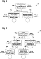
- FIG 4 shows an exemplary inadvertent capsizing avoidance buoyancy system activation fault tree 15.
- Fault tree 15 represents a safety assessment that is based on requirements according to FAR Part 29.1309 or EASA CS 29.1309 for a classification "CATASTROPHIC" of an unintended release of the capsizing avoidance buoyancy system 8 of Figure 1 .
- the capsizing avoidance buoyancy system 8 of Figure 1 i. e. its constituent components, are preferably embodied with respect to an inadvertent release such that they provide for a qualitative function development assurance level A (FDAL-A) according to SAE-ARP-4754-A and a quantitative requirement for a failure probability of Q ⁇ 10 -9 /flight hour (Fh).
- FDAL-A qualitative function development assurance level A
- SAE-ARP-4754-A a quantitative requirement for a failure probability of Q ⁇ 10 -9 /flight hour
- a qualitative item development assurance level C iDAL-C
- a quantitative requirement for a failure probability of Q ⁇ 5 ⁇ 10 -5 /Fh should preferably be met.
- an inadvertent capsizing avoidance buoyancy system powering which is e. g.
- an iDAL-A and a requirement for a failure probability of Q ⁇ 10 -5 /Fh should preferably be met.
- FIG. 5 shows an exemplary capsizing avoidance buoyancy system loss fault tree 16.
- Fault tree 16 represents a safety assessment that is based on requirements according to FAR Part 29.1309 or EASA CS 29.1309 for a classification "CATASTROPHIC" of a loss of the capsizing avoidance buoyancy system 8 of Figure 1 .
- the capsizing avoidance buoyancy system 8 of Figure 1 i. e. its constituent components, are preferably embodied with respect to a possible loss such that they provide for a FDAL-A according to SAE-ARP-4754-A and a requirement for a failure probability of Q ⁇ 10 -9 /Fh.
- an iDAL-A and a requirement for a failure probability of Q ⁇ 5 ⁇ 10 -6 /Fh should preferably be met.
- a loss of electrical chain for respective capsizing avoidance buoyancy devices such as e. g.
- an iDAL-A and a requirement for a failure probability of Q ⁇ 5 ⁇ 10 -6 /Fh should preferably be met.
- a damage of the emergency floatation system 7 of Figure 1 such as e. g. of the float bags 7a of Figure 1
- a current sea state that may lead to capsizing of the helicopter 1 of Figure 1
- a FDAL-C and a requirement for a failure probability of Q ⁇ 10 -4 /Fh should preferably be met.
- the capsizing avoidance buoyancy device 8 of Figure 1 itself, which exemplarily comprises a roof mounted buoyancy device 8a in Figure 1 , which is preferably connected to a gas cylinder and a valve, should preferentially be designed to fulfill a quantitative requirement significant below 10 -9 /Fh.
- the qualitative requirement iDAL A could be seen according SAE ARP 4754 as fulfilled.
- the quantitative requirement for a respective electrical release is also required to be significant below 10 -5 /Fh, which can be fulfilled by activation of the capsizing avoidance buoyancy system 8 of Figure 1 (i. e. the roof mounted buoyancy device 8a of Figure 1 ) in combination with a sensor detecting water and/or stop of rotor.
- a respective qualitative iDAL can be fulfilled by using a powering route and an independent release route, both iDAL-B or one of them iDAL-A and the other one iDAL-C. Simple sensors and contactors are able to fulfill these requirements.
- an actuation logic i. e. the capsizing avoidance buoyancy system actuation system 9 of Figure 2 , can be by this sufficiently developed according iDAL-C.
- the capsizing avoidance buoyancy system of Figure 1 is linked to the emergency floatation system 7 of Figure 1 . If the latter is not already activated, the capsizing avoidance buoyancy system of Figure 1 preferably remains unpowered.
- the emergency floatation system 7 of Figure 1 respective safety figures for unintended activation are already above the "CATASTROPHIC" event classification described above. More specifically, there are already two different events defined, i. e. flight over water with emergency floatation system already armed and flight over land with emergency floatation system not armed.
- the failure probability for unintended activation of the dedicated sensor(s) of the capsizing avoidance buoyancy system 8 of Figure 1 is below 10 -5 /Fh.
Description
- The invention is related to an aircraft with an emergency floatation system, the emergency floatation system being activated upon an emergency landing of the aircraft on water, for preventing at least sinking of the aircraft.
- Aircrafts that are foreseen for flight missions over areas of sea must be equipped with a suitable emergency floatation system that is activated upon an emergency landing of the aircraft on the water, for preventing at least sinking of the aircraft. Exemplary emergency floatation systems with landing gear mounted inflatable floatation devices resp. float bags that are adapted to keep an aircraft stable within certified limits are e. g. described in the
documents EP 2 262 685 A1 ,US 2010/0230534 A1 ,US 7,309,267 B1 andWO 2003/26959 A2 documents EP 2 678 220 A1 ,US 3,189,301 andGB 364,827 WO 2015/193810 A1 andWO 2015/05797 A1 - More generally, respective requirements, i. e. underlying airworthiness standards are defined in applicable safety regulations and specifications, such as the US-American Federal Aviation Regulations (FAR) and/or the European Certification Specifications (CS) from the European Aviation Safety Agency (EASA). In particular, the safety regulations and specifications FAR Part 29 and FAR Part 27 resp. EASA CS-29 and EASA CS-27 define airworthiness standards for rotary wing aircrafts, according to which such rotary wing aircrafts must be equipped with the above-mentioned emergency floatation systems. These safety regulations and specifications further define an air pocket requirement for newly certified rotary wing aircrafts.
- By way of example, this air pocket requirement can be complied with by provision of a suitable capsizing avoidance buoyancy system, e. g. comprising a roof mounted inflatable floatation device resp. float bag, in addition to a normal emergency floatation system. Such a roof mounted float bag is located in a given rotary wing aircraft comparatively close to respective main rotor blades of an associated main rotor and it is specifically needed when, upon an emergency landing of the given rotary wing aircraft on water, a respective sea state is above predetermined emergency floatation system limits of the normal emergency floatation system of the given rotary wing aircraft, as this could lead to a rotation of the rotary wing aircraft into a capsized position.
- However, an unintended release of the capsizing avoidance buoyancy system during flight of the rotary wing aircraft, i. e. an unintended inflation of the roof mounted float bag, e. g. because of a system error, must be avoided as otherwise the inflated float bag may get in contact with the rotating main rotor blades. As this may cause damage and even rupture of one or more of the rotating main rotor blades, a crash of the rotary wing aircraft may become inevitable. Furthermore, non-activation of successive required actions upon an emergency landing of the given rotary wing aircraft on water, such as e. g. omission of release of the roof mounted float bag, which may be caused by unconsciousness of a respective aircraft crew, may result in capsizing of the given rotary wing aircraft despite the provision of the capsizing avoidance buoyancy system. Therefore, an applied inflation logic for the capsizing avoidance buoyancy system must be safe and reliable and should, preferably, be operator-independent.
- It should be noted that a multiplicity of buoyancy systems with more or less operator-independent inflation logic already exists. This multiplicity of buoyancy systems relates, however, not necessarily to capsizing avoidance buoyancy systems, but more broadly to buoyancy systems in general, i. e. also to buoyancy systems that merely implement the above-described emergency floatation systems.
- For instance, the document
US 2012/0132741 A1 describes a semi-automated emergency buoyancy system for an aircraft that is configured for limiting the risk of untimely triggering. More specifically, this buoyancy system comprises at least one float and deployment means for deploying the float, as well as engagement means for activating the deployment means of the float. The buoyancy system further comprises at least two immersion sensors for issuing an order for automatic deployment of the float to the deployment means, which are provided with a memory containing a pre-established list of events and configured to deploy the float when a predetermined event occurs. However, the engagement means are activated only manually, i. e. they must be voluntarily activated by a person, e. g. a pilot of the aircraft, so that the emergency buoyancy system is not completely operator-independent. - The
document EP 2 610 171 A1 describes an aircraft with an external life raft system outside a cabin that comprises an automatic system for water detection. More specifically, the external life raft system comprises life raft containers with associated life rafts on either side of a longitudinal aircraft axis, each life raft container having at least one water sensor and at least one vibration sensor. The external life raft system comprises electrical activation means for an automated activation of the life rafts by means of a logic circuit after a suitable analysis of data provided by the sensors. However, this automated activation is merely described with respect to the external life raft system, while activation and even provision of an emergency floatation system as described above is not described. In other words, the external life raft system is described as a stand-alone system with one step approach for water detection only. - The document XP055360113 (EASA.2007.C16, « Study on Helicopter Ditching and Crashworthiness », by DENANTE, ANTOMARCHI, COUANT and DELORME), which is considered as the closest prior art, describes in particular in chapter V.8. "Deployment (page 35-39)", the inflation of an additional EFS which can be done at three different moments, i.e. in flight, after ditching or after capsize. For Inflation in capsize position, the deployment is done automatically, after capsizing trough sensors (angle, immersion). If sensors do not work properly, inflation may not happen or contrarily could happen inopportunely.
- The document
US2014319265 describes a method of automatically triggering an emergency buoyancy system for a hybrid helicopter having a fuselage, two half-wings and two propulsive propellers. As per the method, said emergency buoyancy system is primed, and then if a risk of said hybrid helicopter ditching is detected, two retractable wing undercarriages are deployed, each wing undercarriage being fastened under a respective half-wing and being provided with at least one immersion sensor. Finally, if the beginning of said hybrid helicopter ditching is detected, at least one main inflatable bag suitable for being arranged under such fuselage and at least one secondary inflatable bag suitable for being arranged under each half-wing are inflated so as to ensure that said hybrid helicopter 20 floats in stable manner. - The document
US3189301 describes a helicopter with a excess buoyancy member defined as a member providing a total buoyancy twice the quantity required to hold the helicopter with its normally vertical center plane in the plane of the water surface. The excess buoyancy member is in the form of an oblate sphere mounted centrally and laterally on the top-side of the rotor head. The buoyancy member is constructed of glass fiber reinforced plastic and is filled with low density rigid polyurethane foam. The excess buoyancy member is secured to the rotor head at four simple attachment points by lugs and bolts. Supplementary flotation members are mounted in the helicopter about its longitudinal center line, disposed in the nose and within the tail structure at a sensibly extreme aft position, respectively. A stabilizing effect of the principal flotation member, is then settled gradually as the water enters the body until the supplementary flotation members become effective to provide pitch stabilization, thereby preventing the nose or tail of the helicopter 1 of plunging. - Other buoyancy systems with more or less automated operator-independent inflation logic are e. g. described in the above-mentioned
EP 2 678 220 A1 - It is, therefore, an object of the present invention to provide a new aircraft that efficiently combines a conventional emergency floatation system with an additional capsizing avoidance buoyancy system.
- This object is solved by an aircraft with an emergency floatation system and a capsizing avoidance buoyancy system, the aircraft comprising the features of claim 1.
- More specifically, according to the present invention the aircraft comprises an emergency floatation system, the emergency floatation system being activated upon an emergency landing of the aircraft on water, for preventing at least sinking of the aircraft. Furthermore, a capsizing avoidance buoyancy system is provided, the capsizing avoidance buoyancy system being activated if predetermined activation criteria are satisfied and only after activation of the emergency floatation system upon an emergency landing of the aircraft on water, for preventing at least capsizing of the aircraft.
- Advantageously, the inventive aircraft comprises a combination of an emergency floatation system, which can e. g. be implemented by means of a conventional emergency floatation system, and a separate capsizing avoidance buoyancy system. The latter is preferably operator-independently, i. e. automatically triggered, e. g. by means of a suitable activation logic, in combination with the emergency floatation system. More specifically, the capsizing avoidance buoyancy system is preferentially only activated if the emergency floatation system is already activated and if capsizing of the aircraft must be expected, e. g. if the aircraft is rotating towards capsized position. Thus, the inventive aircraft implements a sequential approach, wherein the capsizing avoidance buoyancy system cannot be activated independent of the emergency floatation system.
- By way of example, a suitable activation logic can be configured such that activation of the capsizing avoidance buoyancy system is only triggered under the following cumulative conditions:
- the aircraft has already ditched,
- the emergency floatation system is already activated, and
- the aircraft is already comprised in a process of rotating into capsized position, e. g. due to a respective sea state that is above predetermined emergency floatation system limits.
- According to one aspect, the capsizing avoidance buoyancy system comprises inflatable and inflating components, wherein the inflatable components are preferably inflated operator-independently, i. e. automatically if required. By way of example, the inflatable and inflating components can be realized by inflatable and inflating components that are currently already used for implementing conventional emergency floatation systems. These components preferably comprise one or more float bags together with a pressurized gas cylinder or a gas generator including an electrical activation system located within a container.
- Preferably, the electrical activation system of the capsizing avoidance buoyancy system is supplied with electrical power from the inventive aircraft. Additionally, a sensor system is preferentially provided and adapted to detect at least a capsized condition of the inventive aircraft and/or, in case of a rotary aircraft, whether a respective main rotor is still rotating. This sensor system may comprise different types of water sensors and/or vibration sensors. Furthermore, a respective choice of positioning of the suitable sensor system in the inventive aircraft can be performed application-specifically.
- As already described above, the operator-independent, i. e. automatic activation of the capsizing avoidance buoyancy system shall have as prerequisite the already activated emergency floatation system. This can e. g. be implemented by blocking the power supply to the electrical activation system or at least the sensor system of the capsizing avoidance buoyancy system as long as the emergency floatation system is not activated.
- In summary, the inventive aircraft comprises a capsizing avoidance buoyancy system that is operator-independently, i. e. automatically activated, if required, on the basis of a suitable analysis of data provided by a respective sensor system. The latter advantageously allows for a detection of water and comprises a predetermined number of sensors, which are selected and positioned in the inventive aircraft in order to enable at least an extremely safe determination of the states "aircraft in flight" and "aircraft in water".
- According to a preferred embodiment, the emergency floatation system comprises at least one float bag, the at least one float bag being inflated upon activation of the emergency floatation system.
- According to a further preferred embodiment, the capsizing avoidance buoyancy system comprises at least one capsizing avoidance buoyancy device, the at least one capsizing avoidance buoyancy device being inflated upon activation of the capsizing avoidance buoyancy system.
- According to a further preferred embodiment, inflation of the at least one capsizing avoidance buoyancy device is only enabled after inflation of the at least one float bag.
- According to the invention, the capsizing avoidance buoyancy system comprises at least one capsizing evaluation unit, the at least one capsizing evaluation unit being activated after activation of the emergency floatation system upon an emergency landing of the aircraft on water, in order to determine whether the predetermined activation criteria are satisfied.
- According to the invention, the at least one capsizing evaluation unit is electrically coupled to an associated power supply, wherein supplying power from the associated power supply to the at least one capsizing evaluation unit is only enabled after activation of the emergency floatation system.
- According to a further preferred embodiment, the capsizing avoidance buoyancy system comprises at least one capsizing avoidance buoyancy device inflation unit, the at least one capsizing avoidance buoyancy device inflation unit being activated for inflating the at least one capsizing avoidance buoyancy device if the at least one capsizing evaluation unit determines that the predetermined activation criteria are satisfied.
- According to a further preferred embodiment, the at least one capsizing avoidance buoyancy device inflation unit is electrically coupled to an associated power supply, wherein supplying power from the associated power supply to the at least one capsizing avoidance buoyancy device inflation unit is only enabled after the at least one capsizing evaluation unit determines that the predetermined activation criteria are satisfied.
- According to a further preferred embodiment, the predetermined activation criteria are satisfied if a respective sea state is above predetermined emergency floatation system limits.
- According to a further preferred embodiment, the predetermined activation criteria are satisfied if a respective inclination angle of the aircraft with respect to a vertical reference line is above a predetermined limit.
- According to a further preferred embodiment, the predetermined activation criteria are satisfied if it is determined that the aircraft is comprised in a capsizing process.
- According to a further preferred embodiment, activation of the capsizing avoidance buoyancy system is performed automatically and operator-independently.
- According to a further preferred embodiment, a fuselage that defines a lower fuselage region and an upper fuselage region are provided, the emergency floatation system being at least partly arranged in the lower fuselage region and the capsizing avoidance buoyancy system being at least partly arranged in the upper fuselage region.
- According to a further preferred embodiment, the aircraft is embodied as a rotary wing aircraft, in particular as a helicopter.
- According to a further preferred embodiment, the rotary wing aircraft comprises a main rotor, wherein the predetermined activation criteria are satisfied if operation of the main rotor is discontinued.
- Preferred embodiments of the invention are outlined by way of example in the following description with reference to the attached drawings. In these attached drawings, identical or identically functioning components and elements are labeled with identical reference numbers and characters and are, consequently, only described once in the following description.
-
Figure 1 shows a perspective view of an aircraft according to the invention, -
Figure 2 shows a schematic diagram of a capsizing avoidance buoyancy system actuation system according to the invention, -
Figure 3 shows an exemplary capsizing avoidance buoyancy device inflation sequence, -
Figure 4 shows an exemplary inadvertent capsizing avoidance buoyancy system activation fault tree, and -
Figure 5 shows an exemplary capsizing avoidance buoyancy system loss fault tree. -
Figure 1 shows an aircraft 1 according to one aspect that is exemplarily illustrated as a rotary wing aircraft and, more particularly, as a helicopter. Thus, for purposes of simplicity and clarity, the aircraft 1 is hereinafter referred to as the "helicopter" 1. - Illustratively, the helicopter 1 comprises at least one multi-blade
main rotor 1a for providing lift and forward or backward thrust during operation. The at least one multi-blademain rotor 1a preferably comprises a plurality ofrotor blades rotor head 1f to arotor shaft 1g, which rotates in operation of the helicopter 1 around an associated rotor axis. - Preferably, the helicopter 1 comprises a
fuselage 2 that exemplarily defines acabin 2a and acockpit 2b. Illustratively, thefuselage 2 comprises alower fuselage region 2c and anupper fuselage region 2d. Thelower fuselage region 2c is preferably connected to alanding gear 1h, which is exemplarily embodied as a skid-type landing gear. Theupper fuselage region 2d preferably defines a roof of the helicopter 1, where therotor head 1f is exemplarily arranged. - Illustratively, the
fuselage 2 is connected to atail boom 3 and exemplarily comprises at least one preferentially shroudedcounter-torque device 4 configured to provide counter-torque during operation, i. e. to counter the torque created by rotation of the at least one multi-blademain rotor 1a for purposes of balancing the helicopter 1 in terms of yaw. The at least onecounter-torque device 4 is illustratively provided at an aft section of thetail boom 3 and preferably comprises atail rotor 4a. The aft section of thetail boom 3 preferably further comprises avertical stabilizer 5 that is provided with abumper 6. Illustratively, thetail boom 3 is also provided with a suitablehorizontal stabilizer 3a. - According to one aspect, the helicopter 1 comprises an emergency floatation system 7 and a capsizing
avoidance buoyancy system 8. The emergency floatation system 7 is preferably adapted for being activated upon an emergency landing of the helicopter 1 on water, for preventing at least sinking of the helicopter 1. The capsizingavoidance buoyancy system 8 is preferably adapted for being activated if predetermined activation criteria are satisfied and only after activation of the emergency floatation system 7 upon an emergency landing of the helicopter 1 on water, for preventing at least capsizing of the helicopter 1. - The emergency floatation system 7 and the capsizing
avoidance buoyancy system 8 are preferentially implemented as two separate systems, such that the emergency floatation system 7 can be operated independent of the capsizingavoidance buoyancy system 8. In other words, an activation of the emergency floatation system 7 does not necessarily entrain an activation of the capsizingavoidance buoyancy system 8. However, in any case at least activation of the capsizingavoidance buoyancy system 8 and, preferentially, activation of the emergency floatation system 7 and the capsizingavoidance buoyancy system 8 is triggered operator-independently, i. e. automatically. - According to one aspect, the emergency floatation system 7 comprises one or
more float bags 7a, in particular inflatable float bags. Illustratively, fourfloat bags 7a are provided, from which threefloat bags 7a are visible inFigure 1 . - By way of example, the emergency floatation system 7 can be realized by using inflatable and inflating components that are currently already used for implementing conventional emergency floatation systems. Such components preferably comprise conventional float bags together with a pressurized gas cylinder or a gas generator including an electrical activation system located within a container. However, such conventional emergency floatation systems are well-known to the person skilled in the art, so that a more detailed description thereof can be omitted for brevity and conciseness.
- The
float bags 7a are preferably inflated upon activation of the emergency floatation system 7. Exemplarily, thefloat bags 7a are provided at least partly at thelower fuselage region 2c and, preferentially, mounted to thelanding gear 1h. However, instead of mounting thefloat bags 7a to thelanding gear 1h, they may alternatively be mounted directly to thefuselage 2 at thelower fuselage region 2c. - According to one aspect, the capsizing
avoidance buoyancy system 8 comprises one or more capsizingavoidance buoyancy devices 8a, which are preferentially also embodied as float bags, in particular inflatable float bags. Illustratively, a single capsizingavoidance buoyancy device 8a is shown. - By way of example, the capsizing
avoidance buoyancy system 8 can be realized by using inflatable and inflating components that are currently used for implementing conventional emergency floatation systems. As described above, such components preferably comprise conventional float bags together with a pressurized gas cylinder or a gas generator including an electrical activation system located within a container. However, as such conventional emergency floatation systems are well-known to the person skilled in the art, a more detailed description thereof as well as a more detailed description of the capsizingavoidance buoyancy system 8 as such can be omitted for brevity and conciseness. - The capsizing
avoidance buoyancy device 8a is preferentially inflated upon activation of the capsizingavoidance buoyancy system 8. Exemplarily, the capsizingavoidance buoyancy device 8a is at least partly roof mounted at theupper fuselage region 2d. However, this roof-mounting is only illustrated by way of example and not for limiting the invention accordingly. Instead, the capsizingavoidance buoyancy device 8a may alternatively be mounted to the helicopter 1 at any other position that is suitable to allow preventing capsizing of the helicopter 1 upon inflation. -
Figure 2 shows an exemplary capsizing avoidance buoyancysystem actuation system 9. According to one aspect, the latter comprises at least acapsizing evaluation unit 9a and a capsizing avoidance buoyancydevice inflation unit 9b. Thecapsizing evaluation unit 9a preferably comprises one or more sensors, preferentially one or more water and/or vibration sensors. The capsizing avoidance buoyancydevice inflation unit 9b is adapted for inflation of one or more capsizing avoidance buoyancy devices (e. g. capsizingavoidance buoyancy device 8a ofFigure 1 ) upon actuation. - According to one aspect, inflation of the one or more capsizing avoidance buoyancy devices is only enabled after activation of an associated emergency floatation system (e. g. associated emergency floatation system 7 of
Figure 1 ), preferably after inflation of one or more float bags (e. g. floatbags 7a ofFigure 1 ) of the associated emergency floatation system. Accordingly, an emergency floatation systemarmed state detector 10 is provided for determining/indicating whether the associated emergency floatation system is ready for being activated and an emergency floatation system activatedstate detector 11 is provided for determining/indicating whether the associated emergency floatation system has been activated, i. e. whether the one or more float bags have been inflated. - By way of example, the
detectors - According to one aspect, an emergency floatation
system state evaluator 12 is provided for evaluating a respective current state of the associated emergency floatation system, i. e. the one or more float bags. Therefore, the emergency floatationsystem state evaluator 12 is preferably at least similarly embodied to an AND gate and preferentially analyses data provided by thedetectors - If both switch states are "ON", the emergency floatation
system state evaluator 12 preferably electrically couples a capsizing evaluationunit power supply 13a to thecapsizing evaluation unit 9a and, thus, releases power supply from thepower supply 13a to thecapsizing evaluation unit 9a. Accordingly, supplying power from thepower supply 13a to thecapsizing evaluation unit 9a is only enabled after activation of the associated emergency floatation system so that thecapsizing evaluation unit 9a is only activated after activation of the associated emergency floatation system, preferentially upon an emergency landing of a given helicopter (e. g. helicopter 1 ofFigure 1 ) on water. - Upon electrically powering the
capsizing evaluation unit 9a, the latter starts determining whether predetermined activation criteria are satisfied. By way of example, the predetermined activation criteria are satisfied if one or more of the following conditions is fulfilled: a respective sea state is above predetermined emergency floatation system limits, a respective inclination angle of the given helicopter with respect to a vertical reference line is above a predetermined limit, the given helicopter is comprised in a capsizing process and/or operation of a main rotor of the given helicopter (e. g. multi-blademain rotor 1a ofFigure 1 ) is discontinued. - According to one aspect, if the
capsizing evaluation unit 9a determines that the predetermined activation criteria are satisfied, thecapsizing evaluation unit 9a preferably electrically couples a capsizing avoidance buoyancy device inflationunit power supply 13b to the capsizing avoidance buoyancydevice inflation unit 9b and, thus, releases power supply from thepower supply 13b to theinflation unit 9b. Accordingly, theinflation unit 9b is activated for inflating one or more capsizing avoidance buoyancy devices (e. g. capsizingavoidance buoyancy device 8a ofFigure 1 ). -
Figure 3 shows an exemplary capsizing avoidance buoyancydevice inflation sequence 14, that can be implemented by means of the capsizing avoidance buoyancysystem actuation system 9 ofFigure 2 , i. e. with the inventive helicopter 1 ofFigure 1 . Thesequence 14 starts with aninitial step 14a. - According to one aspect, in
step 14a occurrence of an emergency situation is determined. More specifically, instep 14a it is determined whether ditching of a given helicopter (e. g. helicopter 1 ofFigure 1 ) on water is imminent or has already occurred. - Then, in step 14b, it is determined whether a respective emergency floatation system (e. g. emergency floatation system 7 of
Figure 1 ) is ready for being activated, i. e. whether the respective emergency floatation system is in armed state. Subsequently, instep 14c, it is determined whether the respective emergency floatation system has been activated, i. e. whether the respective emergency floatation system is in activated state. More specifically,step 14c may comprise a determination on whether one or more float bags of the respective emergency floatation system (e. g. float bags 7a ofFigure 1 ) have been inflated. - Subsequently, in
step 14d, it is determined whether a respective sea state is above predetermined emergency floatation system limits. Furthermore, instep 14e, it is determined whether the given helicopter is already in a capsizing situation, i. e. whether the given helicopter already rotated or is already rotating into capsized position. Preferably, steps 14d and 14e are performed by means of thecapsizing evaluation unit 9a ofFigure 2 . - Finally, in
step 14f, if the determinations insteps e. g. inflation unit 9b ofFigure 2 ) is activated for inflating one or more capsizing avoidance buoyancy devices (e. g. capsizingavoidance buoyancy device 8a ofFigure 1 ). In other words, an underlying capsizing avoidance buoyancy system (e. g. capsizingavoidance buoyancy system 8 ofFigure 1 ) is activated. - It should, however, be noted that the order of the
steps 14a to 14f, as well as respective measures that are taken at specific steps, are merely exemplary and not for limiting the invention accordingly. Instead, other measures and/or another sequential procedure is likewise possible and, therefore, contemplated. For instance, step 14b may be performed prior tostep 14a orstep 14e may be performed prior tostep 14d. Similarly, whilestep 14d is only described as a determination on whether a respective sea state is above predetermined emergency floatation system limits, it may more generally be intended to detect an instability state of the given helicopter that has ditched on the water. Such an instability state is e. g. given if a respective inclination angle of the given helicopter with respect to a vertical reference line is above a predetermined limit and/or if operation of a main rotor of the given helicopter (e. g. multi-blademain rotor 1a ofFigure 1 ) is discontinued. -
Figure 4 shows an exemplary inadvertent capsizing avoidance buoyancy systemactivation fault tree 15.Fault tree 15 represents a safety assessment that is based on requirements according to FAR Part 29.1309 or EASA CS 29.1309 for a classification "CATASTROPHIC" of an unintended release of the capsizingavoidance buoyancy system 8 ofFigure 1 . Accordingly, the capsizingavoidance buoyancy system 8 ofFigure 1 , i. e. its constituent components, are preferably embodied with respect to an inadvertent release such that they provide for a qualitative function development assurance level A (FDAL-A) according to SAE-ARP-4754-A and a quantitative requirement for a failure probability of Q<10-9/flight hour (Fh). - More specifically, with respect to an inadvertent capsizing avoidance buoyancy system activation by sensor, which is e. g. initiated by the
capsizing evaluation unit 9a ofFigure 2 and illustratively referred to with thereference sign 15a, a qualitative item development assurance level C (iDAL-C) and a quantitative requirement for a failure probability of Q<5∗10-5/Fh should preferably be met. Furthermore, with respect to an inadvertent capsizing avoidance buoyancy system powering, which is e. g. initiated by the emergency floatation system state evaluator 12 ofFigure 2 and illustratively referred to with thereference sign 15b, an iDAL-A and a requirement for a failure probability of Q<10-5/Fh should preferably be met. - As a result, when combining the qualitative assurance levels and the quantitative requirements according to 15a, 15b illustratively by means of an AND-
conjunction 15c in thefault tree 15, a resultant FDAL-A and a resultant requirement for a failure probability of Q<10-9/Fh are obtained. As described above, this resultant FDAL-A and this resultant requirement for a failure probability of Q<10-9/Fh are preferably considered during design of the capsizingavoidance buoyancy system 8 ofFigure 1 , i. e. its constituent components, with respect to an inadvertent release, wherein the capsizingavoidance buoyancy system 8 ofFigure 1 , i. e. its constituent components is/are correspondingly configured, as illustratively indicated atreference sign 15d. -
Figure 5 shows an exemplary capsizing avoidance buoyancy systemloss fault tree 16.Fault tree 16 represents a safety assessment that is based on requirements according to FAR Part 29.1309 or EASA CS 29.1309 for a classification "CATASTROPHIC" of a loss of the capsizingavoidance buoyancy system 8 ofFigure 1 . Accordingly, the capsizingavoidance buoyancy system 8 ofFigure 1 , i. e. its constituent components, are preferably embodied with respect to a possible loss such that they provide for a FDAL-A according to SAE-ARP-4754-A and a requirement for a failure probability of Q<10-9/Fh. - More specifically, with respect to a damage of the capsizing
avoidance buoyancy system 8 ofFigure 1 , such as e. g. of the capsizingavoidance buoyancy device 8a ofFigure 1 and/or the capsizing avoidance buoyancysystem actuation system 9 ofFigure 2 , which is illustratively referred to with thereference sign 16a, an iDAL-A and a requirement for a failure probability of Q<5∗10-6/Fh should preferably be met. Furthermore, with respect to a loss of electrical chain for respective capsizing avoidance buoyancy devices, such as e. g. of the capsizing avoidance buoyancy device inflationunit power supply 13b ofFigure 2 , which is illustratively referred to with thereference sign 16b, an iDAL-A and a requirement for a failure probability of Q<5∗10-6/Fh should preferably be met. - When combining the qualitative assurance levels and the quantitative requirements according to 16a, 16b illustratively by means of an OR-
conjunction 16c in thefault tree 16, a resultant FDAL-A and a resultant requirement for a failure probability of Q<10-5/Fh are obtained. This resultant FDAL-A and this resultant requirement for a failure probability of Q<10-5/Fh are preferably considered during design of the capsizingavoidance buoyancy system 8 ofFigure 1 , i. e. its constituent components, with respect to a potential loss of inflation capability of the capsizingavoidance buoyancy system 8 ofFigure 1 , as illustratively indicated atreference sign 16d. Furthermore, with respect to a damage of the emergency floatation system 7 ofFigure 1 , such as e. g. of thefloat bags 7a ofFigure 1 , and/or with respect to a current sea state that may lead to capsizing of the helicopter 1 ofFigure 1 , both of which are illustratively referred to with thereference sign 16e, a FDAL-C and a requirement for a failure probability of Q<10-4/Fh should preferably be met. - As a result, when combining the qualitative assurance levels and the quantitative requirements according to 16d, 16e illustratively by means of an AND-
conjunction 16f in thefault tree 16, a resultant FDAL-A and a resultant requirement for a failure probability of Q<10-9/Fh are obtained. As described above, this resultant FDAL-A and this resultant requirement for a failure probability of Q<10-9/Fh are preferably considered during design of the capsizingavoidance buoyancy system 8 ofFigure 1 , i. e. its constituent components, which is/are, thus, correspondingly configured with respect to a possible loss, as illustratively indicated atreference sign 16g. - In summary, based on the
generic fault trees Figure 4 and Figure 5 , requirements for the emergency floatation system 7 ofFigure 1 and, more particularly, for the capsizingavoidance buoyancy system 8 ofFigure 1 and its constituent components are defined. The capsizingavoidance buoyancy device 8 ofFigure 1 itself, which exemplarily comprises a roof mountedbuoyancy device 8a inFigure 1 , which is preferably connected to a gas cylinder and a valve, should preferentially be designed to fulfill a quantitative requirement significant below 10-9/Fh. The qualitative requirement iDAL A could be seen according SAE ARP 4754 as fulfilled. - Furthermore, the quantitative requirement for a respective electrical release is also required to be significant below 10-5/Fh, which can be fulfilled by activation of the capsizing
avoidance buoyancy system 8 ofFigure 1 (i. e. the roof mountedbuoyancy device 8a ofFigure 1 ) in combination with a sensor detecting water and/or stop of rotor. A respective qualitative iDAL can be fulfilled by using a powering route and an independent release route, both iDAL-B or one of them iDAL-A and the other one iDAL-C. Simple sensors and contactors are able to fulfill these requirements. Moreover, an actuation logic, i. e. the capsizing avoidance buoyancysystem actuation system 9 ofFigure 2 , can be by this sufficiently developed according iDAL-C. - In addition, as described above, the capsizing avoidance buoyancy system of
Figure 1 is linked to the emergency floatation system 7 ofFigure 1 . If the latter is not already activated, the capsizing avoidance buoyancy system ofFigure 1 preferably remains unpowered. For the emergency floatation system 7 ofFigure 1 , respective safety figures for unintended activation are already above the "CATASTROPHIC" event classification described above. More specifically, there are already two different events defined, i. e. flight over water with emergency floatation system already armed and flight over land with emergency floatation system not armed. Thus, the failure probability for unintended activation of the dedicated sensor(s) of the capsizingavoidance buoyancy system 8 ofFigure 1 is below 10-5/Fh. -
- 1
- rotary wing aircraft
- 1a
- multi-blade main rotor
- 1b, 1c, 1d, 1e
- rotor blades
- 1f
- rotor head
- 1g
- rotor shaft
- 1h
- landing gear
- 2
- fuselage
- 2a
- cabin
- 2b
- cockpit
- 2c
- lower fuselage region
- 2d
- upper fuselage region
- 3
- tail boom
- 3a
- horizontal stabilizer
- 4
- counter-torque device
- 4a
- tail rotor
- 5
- vertical stabilizer
- 6
- bumper
- 7
- emergency floatation system
- 7a
- float bags
- 8
- capsizing avoidance buoyancy system
- 8a
- capsizing avoidance buoyancy device
- 9
- capsizing avoidance buoyancy system actuation system
- 9a
- capsizing evaluation unit
- 9b
- capsizing avoidance buoyancy device inflation unit
- 10
- emergency floatation system armed state detector
- 11
- emergency floatation system activated state detector
- 12
- emergency floatation system state evaluator
- 13a
- capsizing evaluation unit power supply
- 13b
- capsizing avoidance buoyancy device inflation unit power supply
- 14
- capsizing avoidance buoyancy device inflation sequence
- 14a
- emergency situation occurrence
- 14b
- emergency floatation system armed state
- 14c
- emergency floatation system activated state
- 14d
- aircraft floatation instability state
- 14e
- imminent aircraft capsizing situation
- 14f
- capsizing avoidance buoyancy device inflation
- 15
- inadvertent capsizing avoidance buoyancy system activation fault tree
- 15a
- inadvertent capsizing avoidance buoyancy system activation by sensor
- 15b
- inadvertent capsizing avoidance buoyancy system powering
- 15c
- AND-conjunction
- 15d
- inadvertent capsizing avoidance buoyancy system actuation
- 16
- capsizing avoidance buoyancy system loss fault tree
- 16a
- damage of capsizing avoidance buoyancy device
- 16b
- loss of electrical chain for capsizing avoidance buoyancy device
- 16c
- OR-conjunction
- 16d
- loss of capsizing avoidance buoyancy device inflation capability
- 16e
- damage of emergency floatation system leading to aircraft capsizing state
- 16f
- AND-conjunction
- 16g
- loss of capsizing avoidance buoyancy system in aircraft emergency condition
Claims (13)
- An aircraft (1) with an emergency floatation system (7), the emergency floatation system (7) being activated upon an emergency landing of the aircraft (1) on water, for preventing at least sinking of the aircraft (1), characterized in that a capsizing avoidance buoyancy system (8) is provided, the capsizing avoidance buoyancy system (8) being activated if predetermined activation criteria are satisfied and only after activation of the emergency floatation system (7) upon an emergency landing of the aircraft (1) on water, for preventing at least capsizing of the aircraft (1) wherein the capsizing avoidance buoyancy system (8) comprises at least one capsizing evaluation unit (9a), the at least one capsizing evaluation unit (9a) being activated after activation of the emergency floatation system (7) upon an emergency landing of the aircraft (1) on water, in order to determine whether the predetermined activation criteria are satisfied, characterized in that the at least one capsizing evaluation unit (9a) is electrically coupled to an associated power supply (13a), wherein supplying power from the associated power supply (13a) to the at least one capsizing evaluation unit (9a) is only enabled after activation of the emergency floatation system (7).
- The aircraft (1) of claim 1,
characterized in that the emergency floatation system (7) comprises at least one float bag (7a), the at least one float bag (7a) being inflated upon activation of the emergency floatation system (7). - The aircraft (1) of claim 2,
characterized in that the capsizing avoidance buoyancy system (8) comprises at least one capsizing avoidance buoyancy device (8a), the at least one capsizing avoidance buoyancy device (8a) being inflated upon activation of the capsizing avoidance buoyancy system (8). - The aircraft (1) of claim 3,
characterized in that inflation of the at least one capsizing avoidance buoyancy device (8a) is only enabled after inflation of the at least one float bag (7a). - The aircraft (1) of any of the claims 1 to 4, characterized in that the capsizing avoidance buoyancy system (8) comprises at least one capsizing avoidance buoyancy device inflation unit (9b), the at least one capsizing avoidance buoyancy device inflation unit (9b) being activated for inflating the at least one capsizing avoidance buoyancy device (8a) if the at least one capsizing evaluation unit (9a) determines that the predetermined activation criteria are satisfied.
- The aircraft (1) of claim 5, characterized in that the at least one capsizing avoidance buoyancy device inflation unit (9b) is electrically coupled to an associated power supply (13b), wherein supplying power from the associated power supply (13b) to the at least one capsizing avoidance buoyancy device inflation unit (9b) is only enabled after the at least one capsizing evaluation unit (9a) determines that the predetermined activation criteria are satisfied.
- The aircraft (1) of claim 1, characterized in that the predetermined activation criteria are satisfied if a respective sea state is above predetermined emergency floatation system limits.
- The aircraft (1) of claim 1, characterized in that the predetermined activation criteria are satisfied if a respective inclination angle of the aircraft (1) with respect to a vertical reference line is above a predetermined limit.
- The aircraft (1) of claim 1, characterized in that the predetermined activation criteria are satisfied if it is determined that the aircraft (1) is comprised in a capsizing process.
- The aircraft (1) of claim 1, characterized in that activation of the capsizing avoidance buoyancy system (8) is performed automatically and operator-independently.
- The aircraft (1) of claim 1, characterized by a fuselage (2) that defines a lower fuselage region (2c) and an upper fuselage region (2d), the emergency floatation system (7) being at least partly arranged in the lower fuselage region (2c) and the capsizing avoidance buoyancy system (8) being at least partly arranged in the upper fuselage region (2d).
- The aircraft (1) of claim 11, which is embodied as a rotary wing aircraft, in particular as a helicopter.
- The aircraft (1) of claim 12, characterized by a main rotor (1a), wherein the predetermined activation criteria are satisfied if operation of the main rotor (1a) is discontinued.
Priority Applications (6)
| Application Number | Priority Date | Filing Date | Title |
|---|---|---|---|
| EP16400037.4A EP3287366B1 (en) | 2016-08-25 | 2016-08-25 | An aircraft with an emergency floatation system |
| CA2972697A CA2972697C (en) | 2016-08-25 | 2017-07-06 | An aircraft with an emergency floatation system |
| AU2017204664A AU2017204664B2 (en) | 2016-08-25 | 2017-07-07 | An aircraft with an emergency floatation system |
| US15/661,142 US20180057153A1 (en) | 2016-08-25 | 2017-07-27 | Aircraft with an emergency floatation system |
| CN201710660530.2A CN107776879B (en) | 2016-08-25 | 2017-08-04 | Aircraft with emergency floatation system |
| KR1020170103787A KR102009815B1 (en) | 2016-08-25 | 2017-08-16 | An aircraft with an emergency floatation system |
Applications Claiming Priority (1)
| Application Number | Priority Date | Filing Date | Title |
|---|---|---|---|
| EP16400037.4A EP3287366B1 (en) | 2016-08-25 | 2016-08-25 | An aircraft with an emergency floatation system |
Publications (2)
| Publication Number | Publication Date |
|---|---|
| EP3287366A1 EP3287366A1 (en) | 2018-02-28 |
| EP3287366B1 true EP3287366B1 (en) | 2020-03-11 |
Family
ID=57047148
Family Applications (1)
| Application Number | Title | Priority Date | Filing Date |
|---|---|---|---|
| EP16400037.4A Active EP3287366B1 (en) | 2016-08-25 | 2016-08-25 | An aircraft with an emergency floatation system |
Country Status (6)
| Country | Link |
|---|---|
| US (1) | US20180057153A1 (en) |
| EP (1) | EP3287366B1 (en) |
| KR (1) | KR102009815B1 (en) |
| CN (1) | CN107776879B (en) |
| AU (1) | AU2017204664B2 (en) |
| CA (1) | CA2972697C (en) |
Families Citing this family (9)
| Publication number | Priority date | Publication date | Assignee | Title |
|---|---|---|---|---|
| WO2019047073A1 (en) * | 2017-09-06 | 2019-03-14 | 深圳市道通智能航空技术有限公司 | Aerial vehicle landing method, aerial vehicle, and computer readable storage medium |
| CN109373033B (en) * | 2018-11-09 | 2020-07-28 | 中国直升机设计研究所 | Waterproof vent valve for helicopter fuel tank |
| US11524772B1 (en) * | 2019-04-22 | 2022-12-13 | Over, Llc | Emergency flotation system (EFS) |
| CN111645875B (en) * | 2020-04-22 | 2022-06-21 | 中国直升机设计研究所 | Helicopter emergency waterline and position design method thereof |
| EP3904215B1 (en) * | 2020-04-30 | 2022-12-28 | AIRBUS HELICOPTERS DEUTSCHLAND GmbH | A life raft system for an aircraft |
| CN112173130A (en) * | 2020-09-25 | 2021-01-05 | 中国直升机设计研究所 | Emergency floating control device and method for civil helicopter |
| CN112173091A (en) * | 2020-09-25 | 2021-01-05 | 中国直升机设计研究所 | Prevent empting pull belt formula helicopter emergency floating system's flotation pontoon |
| US11753161B2 (en) * | 2022-01-28 | 2023-09-12 | Tony Wayne Thomas, SR. | Buoyancy and impact recovery system |
| KR102633171B1 (en) * | 2022-10-25 | 2024-02-05 | 김현수 | Fuselage Emergency Flotation System for Light Aircraft with Fuselage, Wings and Multiple Landing gears for Takeoff and Landing |
Family Cites Families (33)
| Publication number | Priority date | Publication date | Assignee | Title |
|---|---|---|---|---|
| GB321074A (en) * | 1928-11-17 | 1929-10-31 | Charles Richard Fairey | Improvements in or relating to flying boats |
| US1818597A (en) * | 1929-07-20 | 1931-08-11 | Glenn L Martin Co | Airplane flotation system |
| US1828641A (en) * | 1930-10-12 | 1931-10-20 | Bergeron Michel | Braking apparatus for aircraft |
| GB364827A (en) | 1930-12-31 | 1932-01-14 | Robert Talbot Youngman | Improvements in or relating to emergency flotation gear for aircraft |
| US1894919A (en) * | 1931-04-09 | 1933-01-17 | Edo Aircraft Corp | Seaplane |
| US2621874A (en) * | 1950-04-17 | 1952-12-16 | Air Cruisers Co | Airborne vehicle and cushioning and/or buoyancy supporting means therefor |
| US3102705A (en) * | 1960-03-28 | 1963-09-03 | Goodyear Tire & Rubber | Flotation device |
| US3154270A (en) * | 1962-08-17 | 1964-10-27 | Hiller Aircraft Company Inc | Amphibious landing gear for helicopter |
| GB994284A (en) | 1963-03-08 | 1965-06-02 | Westland Aircraft Ltd | Improvements in or relating to flotation devices for helicopters |
| FR1485723A (en) * | 1966-05-12 | 1967-06-23 | Sud Aviation | Development of helicopter landing and buoyancy devices, mainly light helicopters |
| US3507466A (en) * | 1968-03-11 | 1970-04-21 | Bell Aerospace Corp | Aircraft undercarriage |
| US4451016A (en) * | 1982-04-08 | 1984-05-29 | The B. F. Goodrich Company | Auxiliary flotation system |
| DE3412008A1 (en) * | 1982-12-21 | 1985-10-03 | Adam 4630 Bochum Magin | Cellular air cushion watercraft or cellular and finger-type air cushion watercraft which can be driven by all land vehicles, can be converted into an aircraft and converted back into a land vehicle/propeller-driven watercraft without lift drive |
| US4541356A (en) * | 1984-05-18 | 1985-09-17 | Tristan Jones | Multihull vessel with capsize prevention means |
| CA1239136A (en) * | 1985-01-31 | 1988-07-12 | Donald B. Arney | Inflatable float assembly for aircraft |
| US4799907A (en) * | 1987-02-03 | 1989-01-24 | Conax Florida Corporation | Survival apparatus |
| JPH09315394A (en) * | 1996-05-31 | 1997-12-09 | Hitachi Zosen Corp | Soft landing device for flying body |
| US6644592B2 (en) * | 2001-09-21 | 2003-11-11 | Apical Industries, Inc. | Floatation system |
| US6709305B2 (en) * | 2001-09-21 | 2004-03-23 | Apical Industries, Inc. | Floatation system including life raft |
| US7156033B2 (en) * | 2002-08-19 | 2007-01-02 | Floatlogic, Inc. | Inflating aircraft flotation device |
| US7309267B1 (en) | 2006-09-25 | 2007-12-18 | Air Cruisers Company | Integrated float raft |
| US7878450B2 (en) | 2006-12-18 | 2011-02-01 | Apical Industries, Inc. | Float pack assembly and method of use |
| GB2457719B (en) | 2008-02-22 | 2010-03-17 | Gkn Aerospace Services Ltd | Emergency flotation apparatus |
| US20100102173A1 (en) * | 2008-10-21 | 2010-04-29 | Everett Michael L | Light Aircraft Stabilization System |
| FR2967972B1 (en) | 2010-11-25 | 2013-05-17 | Eurocopter France | METHOD FOR CONTROLLING AN AIRCRAFT FLOATING SYSTEM AND FLOATING SYSTEM USING THE SAME, AND AIRCRAFT |
| JP6219171B2 (en) * | 2011-02-25 | 2017-10-25 | アルキメデス プロプライエタリー リミテッドArchimedes Pty Ltd. | Buoyancy system |
| EP2610171B1 (en) | 2011-12-29 | 2014-09-10 | AIRBUS HELICOPTERS DEUTSCHLAND GmbH | An aircraft with an automatic system for water detection |
| FR2997923B1 (en) | 2012-11-14 | 2014-11-28 | Eurocopter France | METHOD FOR AUTOMATICALLY RELEASING A HYBRID HELICOPTERS EMERGENCY FLOATABILITY SYSTEM |
| US11260982B2 (en) * | 2013-03-06 | 2022-03-01 | Textron Innovations Inc. | Crash load attenuator for water ditching and floatation |
| NO336056B1 (en) | 2013-07-01 | 2015-04-27 | Helicopter Secure System As | Device at lower keel |
| FR3017107A1 (en) * | 2014-01-31 | 2015-08-07 | Airbus Helicopters | FLOATING SYSTEM FOR AIRCRAFT AND AIRCRAFT |
| US9573666B2 (en) | 2014-06-17 | 2017-02-21 | Zodiac Aerosafety Systems | Longitudinal scoops for rolling stability |
| FR3047231B1 (en) * | 2016-01-29 | 2018-01-05 | Airbus Helicopters | CONTROL METHOD FOR CONTROLLING A FLOATING SYSTEM FOR AN AIRCRAFT, FLOAT SYSTEM AND AIRCRAFT |
-
2016
- 2016-08-25 EP EP16400037.4A patent/EP3287366B1/en active Active
-
2017
- 2017-07-06 CA CA2972697A patent/CA2972697C/en active Active
- 2017-07-07 AU AU2017204664A patent/AU2017204664B2/en active Active
- 2017-07-27 US US15/661,142 patent/US20180057153A1/en not_active Abandoned
- 2017-08-04 CN CN201710660530.2A patent/CN107776879B/en active Active
- 2017-08-16 KR KR1020170103787A patent/KR102009815B1/en active IP Right Grant
Non-Patent Citations (1)
| Title |
|---|
| None * |
Also Published As
| Publication number | Publication date |
|---|---|
| CA2972697C (en) | 2019-05-07 |
| AU2017204664A1 (en) | 2018-03-15 |
| KR20180023825A (en) | 2018-03-07 |
| EP3287366A1 (en) | 2018-02-28 |
| CN107776879A (en) | 2018-03-09 |
| AU2017204664B2 (en) | 2018-11-15 |
| US20180057153A1 (en) | 2018-03-01 |
| CN107776879B (en) | 2020-12-22 |
| KR102009815B1 (en) | 2019-08-12 |
| CA2972697A1 (en) | 2017-09-13 |
Similar Documents
| Publication | Publication Date | Title |
|---|---|---|
| EP3287366B1 (en) | An aircraft with an emergency floatation system | |
| US9315263B2 (en) | Method of automatically triggering an emergency buoyancy system for a hybrid helicopter | |
| AU2012220372B2 (en) | Buoyancy system | |
| EP2444321B1 (en) | Device for locating aircraft involved in an accident | |
| US20110276232A1 (en) | Method of controlling a buoyancy system for an aircraft, and a control system implementing said method | |
| US8888044B2 (en) | Aircraft provided with a buoyancy system for a rotary element | |
| CN102481980B (en) | Aircraft occupant protection system | |
| US11591053B2 (en) | Life raft system for an aircraft | |
| US11584518B2 (en) | Aircraft provided with a buoyancy system, and a buoyancy method | |
| EP2610171B1 (en) | An aircraft with an automatic system for water detection | |
| Patel et al. | Transport water impact and ditching performance | |
| US20230227167A1 (en) | Parachute and inflatable assembly for air taxi | |
| RU2646030C2 (en) | Method for saving the aircraft in case of the accident, the device for its implementation and the roll-off sensor | |
| Brooks et al. | The abysmal performance of the inflatable liferaft in helicopter ditchings | |
| JP2004051070A (en) | Rescue equipment at crash or emergency landing of aircraft | |
| Lindenau et al. | Review of Transport Aircraft Ditching accidents |
Legal Events
| Date | Code | Title | Description |
|---|---|---|---|
| PUAI | Public reference made under article 153(3) epc to a published international application that has entered the european phase |
Free format text: ORIGINAL CODE: 0009012 |
|
| STAA | Information on the status of an ep patent application or granted ep patent |
Free format text: STATUS: THE APPLICATION HAS BEEN PUBLISHED |
|
| STAA | Information on the status of an ep patent application or granted ep patent |
Free format text: STATUS: REQUEST FOR EXAMINATION WAS MADE |
|
| AK | Designated contracting states |
Kind code of ref document: A1 Designated state(s): AL AT BE BG CH CY CZ DE DK EE ES FI FR GB GR HR HU IE IS IT LI LT LU LV MC MK MT NL NO PL PT RO RS SE SI SK SM TR |
|
| AX | Request for extension of the european patent |
Extension state: BA ME |
|
| 17P | Request for examination filed |
Effective date: 20180206 |
|
| RBV | Designated contracting states (corrected) |
Designated state(s): AL AT BE BG CH CY CZ DE DK EE ES FI FR GB GR HR HU IE IS IT LI LT LU LV MC MK MT NL NO PL PT RO RS SE SI SK SM TR |
|
| STAA | Information on the status of an ep patent application or granted ep patent |
Free format text: STATUS: EXAMINATION IS IN PROGRESS |
|
| 17Q | First examination report despatched |
Effective date: 20181204 |
|
| GRAP | Despatch of communication of intention to grant a patent |
Free format text: ORIGINAL CODE: EPIDOSNIGR1 |
|
| STAA | Information on the status of an ep patent application or granted ep patent |
Free format text: STATUS: GRANT OF PATENT IS INTENDED |
|
| INTG | Intention to grant announced |
Effective date: 20191125 |
|
| GRAS | Grant fee paid |
Free format text: ORIGINAL CODE: EPIDOSNIGR3 |
|
| GRAA | (expected) grant |
Free format text: ORIGINAL CODE: 0009210 |
|
| STAA | Information on the status of an ep patent application or granted ep patent |
Free format text: STATUS: THE PATENT HAS BEEN GRANTED |
|
| AK | Designated contracting states |
Kind code of ref document: B1 Designated state(s): AL AT BE BG CH CY CZ DE DK EE ES FI FR GB GR HR HU IE IS IT LI LT LU LV MC MK MT NL NO PL PT RO RS SE SI SK SM TR |
|
| REG | Reference to a national code |
Ref country code: GB Ref legal event code: FG4D |
|
| REG | Reference to a national code |
Ref country code: CH Ref legal event code: EP |
|
| REG | Reference to a national code |
Ref country code: AT Ref legal event code: REF Ref document number: 1242855 Country of ref document: AT Kind code of ref document: T Effective date: 20200315 |
|
| REG | Reference to a national code |
Ref country code: IE Ref legal event code: FG4D |
|
| REG | Reference to a national code |
Ref country code: DE Ref legal event code: R096 Ref document number: 602016031442 Country of ref document: DE |
|
| PG25 | Lapsed in a contracting state [announced via postgrant information from national office to epo] |
Ref country code: NO Free format text: LAPSE BECAUSE OF FAILURE TO SUBMIT A TRANSLATION OF THE DESCRIPTION OR TO PAY THE FEE WITHIN THE PRESCRIBED TIME-LIMIT Effective date: 20200611 Ref country code: RS Free format text: LAPSE BECAUSE OF FAILURE TO SUBMIT A TRANSLATION OF THE DESCRIPTION OR TO PAY THE FEE WITHIN THE PRESCRIBED TIME-LIMIT Effective date: 20200311 Ref country code: FI Free format text: LAPSE BECAUSE OF FAILURE TO SUBMIT A TRANSLATION OF THE DESCRIPTION OR TO PAY THE FEE WITHIN THE PRESCRIBED TIME-LIMIT Effective date: 20200311 |
|
| REG | Reference to a national code |
Ref country code: NL Ref legal event code: MP Effective date: 20200311 |
|
| PG25 | Lapsed in a contracting state [announced via postgrant information from national office to epo] |
Ref country code: GR Free format text: LAPSE BECAUSE OF FAILURE TO SUBMIT A TRANSLATION OF THE DESCRIPTION OR TO PAY THE FEE WITHIN THE PRESCRIBED TIME-LIMIT Effective date: 20200612 Ref country code: HR Free format text: LAPSE BECAUSE OF FAILURE TO SUBMIT A TRANSLATION OF THE DESCRIPTION OR TO PAY THE FEE WITHIN THE PRESCRIBED TIME-LIMIT Effective date: 20200311 Ref country code: SE Free format text: LAPSE BECAUSE OF FAILURE TO SUBMIT A TRANSLATION OF THE DESCRIPTION OR TO PAY THE FEE WITHIN THE PRESCRIBED TIME-LIMIT Effective date: 20200311 Ref country code: LV Free format text: LAPSE BECAUSE OF FAILURE TO SUBMIT A TRANSLATION OF THE DESCRIPTION OR TO PAY THE FEE WITHIN THE PRESCRIBED TIME-LIMIT Effective date: 20200311 Ref country code: BG Free format text: LAPSE BECAUSE OF FAILURE TO SUBMIT A TRANSLATION OF THE DESCRIPTION OR TO PAY THE FEE WITHIN THE PRESCRIBED TIME-LIMIT Effective date: 20200611 |
|
| REG | Reference to a national code |
Ref country code: LT Ref legal event code: MG4D |
|
| PG25 | Lapsed in a contracting state [announced via postgrant information from national office to epo] |
Ref country code: NL Free format text: LAPSE BECAUSE OF FAILURE TO SUBMIT A TRANSLATION OF THE DESCRIPTION OR TO PAY THE FEE WITHIN THE PRESCRIBED TIME-LIMIT Effective date: 20200311 |
|
| PG25 | Lapsed in a contracting state [announced via postgrant information from national office to epo] |
Ref country code: EE Free format text: LAPSE BECAUSE OF FAILURE TO SUBMIT A TRANSLATION OF THE DESCRIPTION OR TO PAY THE FEE WITHIN THE PRESCRIBED TIME-LIMIT Effective date: 20200311 Ref country code: LT Free format text: LAPSE BECAUSE OF FAILURE TO SUBMIT A TRANSLATION OF THE DESCRIPTION OR TO PAY THE FEE WITHIN THE PRESCRIBED TIME-LIMIT Effective date: 20200311 Ref country code: CZ Free format text: LAPSE BECAUSE OF FAILURE TO SUBMIT A TRANSLATION OF THE DESCRIPTION OR TO PAY THE FEE WITHIN THE PRESCRIBED TIME-LIMIT Effective date: 20200311 Ref country code: RO Free format text: LAPSE BECAUSE OF FAILURE TO SUBMIT A TRANSLATION OF THE DESCRIPTION OR TO PAY THE FEE WITHIN THE PRESCRIBED TIME-LIMIT Effective date: 20200311 Ref country code: IS Free format text: LAPSE BECAUSE OF FAILURE TO SUBMIT A TRANSLATION OF THE DESCRIPTION OR TO PAY THE FEE WITHIN THE PRESCRIBED TIME-LIMIT Effective date: 20200711 Ref country code: SK Free format text: LAPSE BECAUSE OF FAILURE TO SUBMIT A TRANSLATION OF THE DESCRIPTION OR TO PAY THE FEE WITHIN THE PRESCRIBED TIME-LIMIT Effective date: 20200311 Ref country code: SM Free format text: LAPSE BECAUSE OF FAILURE TO SUBMIT A TRANSLATION OF THE DESCRIPTION OR TO PAY THE FEE WITHIN THE PRESCRIBED TIME-LIMIT Effective date: 20200311 Ref country code: PT Free format text: LAPSE BECAUSE OF FAILURE TO SUBMIT A TRANSLATION OF THE DESCRIPTION OR TO PAY THE FEE WITHIN THE PRESCRIBED TIME-LIMIT Effective date: 20200805 |
|
| REG | Reference to a national code |
Ref country code: AT Ref legal event code: MK05 Ref document number: 1242855 Country of ref document: AT Kind code of ref document: T Effective date: 20200311 |
|
| REG | Reference to a national code |
Ref country code: DE Ref legal event code: R097 Ref document number: 602016031442 Country of ref document: DE |
|
| PLBE | No opposition filed within time limit |
Free format text: ORIGINAL CODE: 0009261 |
|
| STAA | Information on the status of an ep patent application or granted ep patent |
Free format text: STATUS: NO OPPOSITION FILED WITHIN TIME LIMIT |
|
| PG25 | Lapsed in a contracting state [announced via postgrant information from national office to epo] |
Ref country code: ES Free format text: LAPSE BECAUSE OF FAILURE TO SUBMIT A TRANSLATION OF THE DESCRIPTION OR TO PAY THE FEE WITHIN THE PRESCRIBED TIME-LIMIT Effective date: 20200311 Ref country code: AT Free format text: LAPSE BECAUSE OF FAILURE TO SUBMIT A TRANSLATION OF THE DESCRIPTION OR TO PAY THE FEE WITHIN THE PRESCRIBED TIME-LIMIT Effective date: 20200311 Ref country code: DK Free format text: LAPSE BECAUSE OF FAILURE TO SUBMIT A TRANSLATION OF THE DESCRIPTION OR TO PAY THE FEE WITHIN THE PRESCRIBED TIME-LIMIT Effective date: 20200311 |
|
| 26N | No opposition filed |
Effective date: 20201214 |
|
| PG25 | Lapsed in a contracting state [announced via postgrant information from national office to epo] |
Ref country code: SI Free format text: LAPSE BECAUSE OF FAILURE TO SUBMIT A TRANSLATION OF THE DESCRIPTION OR TO PAY THE FEE WITHIN THE PRESCRIBED TIME-LIMIT Effective date: 20200311 Ref country code: PL Free format text: LAPSE BECAUSE OF FAILURE TO SUBMIT A TRANSLATION OF THE DESCRIPTION OR TO PAY THE FEE WITHIN THE PRESCRIBED TIME-LIMIT Effective date: 20200311 |
|
| PG25 | Lapsed in a contracting state [announced via postgrant information from national office to epo] |
Ref country code: MC Free format text: LAPSE BECAUSE OF FAILURE TO SUBMIT A TRANSLATION OF THE DESCRIPTION OR TO PAY THE FEE WITHIN THE PRESCRIBED TIME-LIMIT Effective date: 20200311 |
|
| REG | Reference to a national code |
Ref country code: CH Ref legal event code: PL |
|
| PG25 | Lapsed in a contracting state [announced via postgrant information from national office to epo] |
Ref country code: CH Free format text: LAPSE BECAUSE OF NON-PAYMENT OF DUE FEES Effective date: 20200831 Ref country code: LU Free format text: LAPSE BECAUSE OF NON-PAYMENT OF DUE FEES Effective date: 20200825 Ref country code: LI Free format text: LAPSE BECAUSE OF NON-PAYMENT OF DUE FEES Effective date: 20200831 |
|
| REG | Reference to a national code |
Ref country code: BE Ref legal event code: MM Effective date: 20200831 |
|
| PG25 | Lapsed in a contracting state [announced via postgrant information from national office to epo] |
Ref country code: IE Free format text: LAPSE BECAUSE OF NON-PAYMENT OF DUE FEES Effective date: 20200825 Ref country code: BE Free format text: LAPSE BECAUSE OF NON-PAYMENT OF DUE FEES Effective date: 20200831 |
|
| PG25 | Lapsed in a contracting state [announced via postgrant information from national office to epo] |
Ref country code: TR Free format text: LAPSE BECAUSE OF FAILURE TO SUBMIT A TRANSLATION OF THE DESCRIPTION OR TO PAY THE FEE WITHIN THE PRESCRIBED TIME-LIMIT Effective date: 20200311 Ref country code: MT Free format text: LAPSE BECAUSE OF FAILURE TO SUBMIT A TRANSLATION OF THE DESCRIPTION OR TO PAY THE FEE WITHIN THE PRESCRIBED TIME-LIMIT Effective date: 20200311 Ref country code: CY Free format text: LAPSE BECAUSE OF FAILURE TO SUBMIT A TRANSLATION OF THE DESCRIPTION OR TO PAY THE FEE WITHIN THE PRESCRIBED TIME-LIMIT Effective date: 20200311 |
|
| PG25 | Lapsed in a contracting state [announced via postgrant information from national office to epo] |
Ref country code: MK Free format text: LAPSE BECAUSE OF FAILURE TO SUBMIT A TRANSLATION OF THE DESCRIPTION OR TO PAY THE FEE WITHIN THE PRESCRIBED TIME-LIMIT Effective date: 20200311 Ref country code: AL Free format text: LAPSE BECAUSE OF FAILURE TO SUBMIT A TRANSLATION OF THE DESCRIPTION OR TO PAY THE FEE WITHIN THE PRESCRIBED TIME-LIMIT Effective date: 20200311 |
|
| P01 | Opt-out of the competence of the unified patent court (upc) registered |
Effective date: 20230530 |
|
| PGFP | Annual fee paid to national office [announced via postgrant information from national office to epo] |
Ref country code: IT Payment date: 20230825 Year of fee payment: 8 Ref country code: GB Payment date: 20230822 Year of fee payment: 8 |
|
| PGFP | Annual fee paid to national office [announced via postgrant information from national office to epo] |
Ref country code: FR Payment date: 20230825 Year of fee payment: 8 Ref country code: DE Payment date: 20230821 Year of fee payment: 8 |