EP3286366B1 - Vorrichtung mit strukturgesteuerten komponenten und textilmaschine mit einer derartigen vorrichtung - Google Patents
Vorrichtung mit strukturgesteuerten komponenten und textilmaschine mit einer derartigen vorrichtung Download PDFInfo
- Publication number
- EP3286366B1 EP3286366B1 EP16725915.9A EP16725915A EP3286366B1 EP 3286366 B1 EP3286366 B1 EP 3286366B1 EP 16725915 A EP16725915 A EP 16725915A EP 3286366 B1 EP3286366 B1 EP 3286366B1
- Authority
- EP
- European Patent Office
- Prior art keywords
- actuators
- actuator
- pattern
- actuator module
- cooling circuit
- Prior art date
- Legal status (The legal status is an assumption and is not a legal conclusion. Google has not performed a legal analysis and makes no representation as to the accuracy of the status listed.)
- Active
Links
Images



Classifications
-
- D—TEXTILES; PAPER
- D03—WEAVING
- D03C—SHEDDING MECHANISMS; PATTERN CARDS OR CHAINS; PUNCHING OF CARDS; DESIGNING PATTERNS
- D03C13/00—Shedding mechanisms not otherwise provided for
- D03C13/02—Shedding mechanisms not otherwise provided for with independent drive motors
- D03C13/025—Shedding mechanisms not otherwise provided for with independent drive motors with independent frame drives
-
- D—TEXTILES; PAPER
- D03—WEAVING
- D03C—SHEDDING MECHANISMS; PATTERN CARDS OR CHAINS; PUNCHING OF CARDS; DESIGNING PATTERNS
- D03C3/00—Jacquards
- D03C3/20—Electrically-operated jacquards
- D03C3/205—Independently actuated lifting cords
-
- D—TEXTILES; PAPER
- D03—WEAVING
- D03D—WOVEN FABRICS; METHODS OF WEAVING; LOOMS
- D03D39/00—Pile-fabric looms
- D03D39/02—Axminster looms, i.e. wherein pile tufts are inserted during weaving
-
- D—TEXTILES; PAPER
- D03—WEAVING
- D03J—AUXILIARY WEAVING APPARATUS; WEAVERS' TOOLS; SHUTTLES
- D03J1/00—Auxiliary apparatus combined with or associated with looms
- D03J1/008—Cooling systems
-
- D—TEXTILES; PAPER
- D05—SEWING; EMBROIDERING; TUFTING
- D05C—EMBROIDERING; TUFTING
- D05C15/00—Making pile fabrics or articles having similar surface features by inserting loops into a base material
- D05C15/04—Tufting
- D05C15/08—Tufting machines
- D05C15/26—Tufting machines with provision for producing patterns
Definitions
- This invention relates to a device equipped with pattern-controlled components for pattern-controlled feeding and/or selection of yarn for a textile machine comprising a plurality of actuators and a cooling circuit through which cooling liquid is flowable for the cooling of the actuators.
- This invention also relates to a Jacquard machine comprising such a device.
- this invention relates to a textile machine comprising such a device.
- Such a textile machine can, for example, be a tufting machine, or a weaving machine, which more specifically can be an Axminster weaving machine.
- Pattern-controlled components known as "pile feeders" are provided to feed the yarn pattern driven to the tufting needles.
- Other pattern-controlled components such as pattern-controlled components that control the hooks under the tuft fabric, with or without knives, are provided to determine the pattern-controlled selection of the pile height and/or pile form, namely pile loops or cut pile.
- Further pattern-controlled components which control the tufting needles directly are provided for the pattern-controlled selection of the yarn to be brought into a base fabric.
- a Jacquard machine is equipped with a very large number of pattern-controlled components for pattern-controlled positioning of the yarn.
- a weaving machine can comprise a Jacquard machine.
- a weaving machine can also be equipped with pattern-controlled components provided to feed the yarn pattern driven in order in this way to determine the pile height of the piles in the carpet.
- the pattern-controlled components can be provided for pattern-controlled selection of the yarn to be brought into a fabric.
- Such an Axminster weaving machine then comprises an Axminster Jacquard machine with such pattern-controlled components provided for pattern-controlled selection of the yarn.
- the actuators used here can be rotary motors, linear motors, stepper motors, voice-coil actuators, hydraulic or pneumatic actuators, solenoids, etc.
- US 6,807,917 B1 describes an example of such a device with yarn feeding modules for feeding yarn into a tufting machine in which the motors are air-cooled. Here a series of fans direct the necessary air over the components to be cooled.
- US 6,058,983 A describes a device wherein actuators for the vertical control of harness threads of a weaving mechanism are air-cooled. Air as a coolant is less effective, however, than other known cooling fluids. In the area around textile machines, the ambient air is warm and dusty so that filters are necessary to remove the dust from the air. Another possibility is to use outside air as cooling air, but this solution requires additional air pipes. Furthermore, in both cases a large contact area is necessary between the actuators and the air in order to be able to dissipate sufficient heat, and a relatively large flow of air is necessary in order to be able to cool the actuators sufficiently.
- the failure percentage of the actuators is relatively limited there and the risks of an interruption of the cooling circuit are more limited there, since the actuators are installed outside the actual working area.
- this invention relates in which dozens, hundreds or even thousands of actuators are installed in a more limited area in the immediate vicinity of the actual working area of the textile machine, and then predominantly above it, however, such water-cooled actuators are barely employed in practice. Due to the large number of actuators, there is a real chance of failure of one of the actuators, and furthermore the risks of consequential damage from the interruption of a water-filled cooling circuit cannot be neglected.
- This object of the invention is achieved by providing a device equipped with pattern-controlled components for pattern-controlled feeding and/or selection of yarn for a textile machine, comprising:
- the replacement of one or more of the actuators is less burdensome and less hazardous than with the known water-cooled actuators in which the cooling circuit runs through these actuators themselves or in which risk of a leak is greater.
- dust-free cooling is now achieved that is also far more efficient.
- the energy losses from the actuators in the form of residual heat can be discharged with a device according to the invention in a simple, operationally safe and efficient manner.
- the cooling of the actuators ensures that the actuators and the connected components can operate in a more limited temperature range and hence can be more appropriately dimensioned or that the operational safety of the actuators and the connected components is increased.
- At least partially integrating the cooling circuit in such a device into the mounting frame allows compact installation of the cooling circuit in the device. In this way the device can either be designed more compactly, or the components of the device can be installed less closely together within the same volume.
- the actuators can thus be made more easily attachable to the mounting frame without obstruction from the additional pipework forming the cooling circuit at the points where this cooling circuit is integrated into the mounting frame or in their immediate vicinity.
- the attachment elements for attaching the actuators to the mounting frame can thus be given the additional function of discharging the heat from the actuators to the cooling circuit.
- a cooling circuit can be provided for each mounting frame of a device according to this invention.
- a cooling circuit of a device according to this invention can also be installed spread across several mounting frames. The cooling circuit can run through the mounting frames in series or in parallel. It is thus possible, for example, to install one cooling circuit for two mounting frames.
- Each actuator module preferably comprises one or more thermally conductive elements to conduct heat from the actuators to the cooling circuit.
- each actuator module is preferably detachably installable in the device by means of the one or more thermally conductive elements.
- thermally conductive elements can provide optimum transfer of the heat.
- the use of such thermally conductive elements for installation of each actuator allows the number of installation elements required for the installation of each actuator in the device to be limited.
- each actuator is preferably installed at least partially separate from the one or more thermally conductive elements. At least one part of each actuator does not border on these one or more thermally conductive elements so that each actuator is not surrounded by these one or more thermally conductive elements. This also allows material to be saved because not all sides of the actuator modules have to be covered by such thermally conductive elements.
- each actuator is hereby preferably installed facing away from the one or more thermally conductive elements. More preferably, each actuator borders on the one or more thermally conductive elements on only one side.
- each actuator module can comprise a thermally conductive plate as said thermally conductive element.
- a thermally conductive plate can ensure a good heat transfer in combination with a simple installation.
- This thermally conductive plate can extend, for example, like a flange relative to each actuator of the actuator module. It can thereby extend like a flange relative to the head of such an actuator.
- thermally conductive elements comprise such a thermally conductive plate
- this thermally conductive plate is preferably detachably fastenable to a said beam through which cooling liquid is flowable for the detachable fastening of the actuator module to this beam.
- this beam can then advantageously form part of the mounting frame.
- each actuator module in a specific embodiment of a device according to this invention which comprises a said mounting frame and the one or more said actuator modules has a guide rib or guide slot and the mounting frame comprises a corresponding guide slot or guide rib to guide the actuator module during installation of said module.
- a special embodiment of a device according to this invention comprises one or more electrical components, whereby the cooling circuit is provided for cooling these electrical components.
- These electrical components can comprise i.a. PCBs, electronic circuits, processors, inverters, relays, etc.
- each actuator module preferably comprises one or more said electrical components.
- these electrical components could also be installed separately from these actuator modules in the device, whereby the actuator modules are installed detachably relative to these electrical components. All said electrical components are preferably contained in the one or more actuator modules. It is also possible to include part of the electrical components in the one or more actuator modules and to install the other part separately from these actuator modules in the device.
- each actuator module comprises one or more said electrical components
- the actuators of each actuator module are preferably installed on both sides of the electrical components of this actuator module.
- each actuator module comprises eight said actuators, four installed on each side of the electrical components.
- a device with one or more said electrical components comprises a said thermally conductive plate in each actuator module, then the actuators and the electrical components in each actuator module are preferably fastened to this thermally conductive plate.
- the cooling liquid in a preferred device according to this invention can be water or a water-based liquid.
- This invention also relates to a Jacquard machine comprising a device equipped with pattern-controlled components, whereby this device is a device according to this invention as described above, provided for pattern-controlled positioning of yarn.
- this invention relates to a textile machine comprising a device equipped with pattern-controlled components, whereby this device is a device according to this invention as described above.
- Such a textile machine according to this invention can, for example, be a tufting machine, an Axminster weaving machine or a weaving machine. Such a weaving machine can then more specifically comprise a said Jacquard machine according to this invention.
- the cooling circuit is furthermore preferably provided for the cooling of one or more mechanical parts of the device and/or of other mechanical and/or electrical parts of this textile machine.
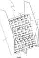
- the figures illustrate a yarn feeding unit (1) for a tufting machine with pattern-controlled components (2) for the pattern-controlled feeding of yarn.
- a yarn feeding unit (1) for a tufting machine with pattern-controlled components (2) for the pattern-controlled feeding of yarn For a person skilled in the art it is clear from this how, by analogy, he can for example devise a yarn feeding unit for a weaving machine for the pattern-controlled feeding of yarn or how, by analogy, he can devise a selection unit for a tufting machine or weaving machine with pattern-controlled components for pattern-controlled selection of yarn.
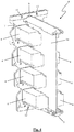
- the illustrated yarn feeding unit (1) comprises a mounting frame (3, 8) to which various yarn feeding modules (6) are detachably fastened.
- the mounting frame (3, 8) comprises two side walls (3) between which a number of beams (8) are installed more or less parallel to each other.
- the beams (8) are hollow and are connected together by pipes (5) to form together a cooling circuit (5, 8) through which water is flowable. In this way this cooling circuit (5, 8) is partially integrated into the mounting frame (3, 8).
- FIGS 4-6 show a separate yarn feeding module (6).
- Each yarn feeding module (6) comprises eight servomotors (4) that are mounted together on a plate (7).
- Four of these motors (4) are installed on each side of an electric circuit (10) which comprises i.a. the electronic components for controlling the servomotors (4).
- This electrical circuit (10) is also mounted on the said plate (7).
- the servomotors (4) are provided in a known manner to control pattern-controlled components (2) for the feeding of yarn for a tufting machine. As this is state-of-the-art and does not form part of the invention, this is not discussed in further detail here.
- the servomotors can be replaced by pneumatic actuators.
- the servomotors can, for example, be typically replaced by rotary or linear stepper motors.
- the servomotors can, for example, be typically replaced by solenoids.
- different numbers of actuators (4) per actuator module (6) may be desired.
- each yarn feeding module (6) is attachable to the beam (8) of the mounting frame (3, 8).
- this plate (7) has screw holes (12) at top and bottom through which screws can be inserted to screw this plate (7) to respective beams (8) of the mounting frame (3, 8).
- the beams (8) of the mounting frame (3, 8) have a stop (11) with which the upper side of the plate (7) can be aligned for simple positioning of the yarn feeding modules (6) relative to the beams (8) before it is screwed tight.
- This plate (7) is thermally conductive in order to be able to dissipate the heat of the motors (4) and the electric circuit (10) to the beams (8) which form part of the cooling circuit (5, 8) through which water is flowable.
- each yarn feeding module (6) comprises a guide rib (9) that can engage and slide in a corresponding guide slot (not illustrated) in the beams (8) in order to guide the yarn feeding module (6) relative to the beams (8) during installation in the yarn feeding unit (1).
- the yarn feeding modules (6) are located completely alongside the cooling circuit (5, 8) in the yarn feeding unit (1) and are detachable from the cooling circuit (5, 8) without having to interrupt this cooling circuit (5, 8).
- the illustrated cooling circuit (5, 8) is provided here for cooling both the motors (4) and the electric circuits (10) of the yarn feeding modules (6). Due to the thermally conductive plates (7), maximum heat from the motors (4) and the electric circuits (10) is discharged to the cooling circuit (5, 8).
- This cooling circuit (5, 8) can also be provided for the cooling of one or more mechanical parts of the device (1) and/or of other mechanical and/or electrical parts of the textile machine in which this device (1) is installed.
Landscapes
- Engineering & Computer Science (AREA)
- Textile Engineering (AREA)
- Treatment Of Fiber Materials (AREA)
- Cooling Or The Like Of Electrical Apparatus (AREA)
- Looms (AREA)
- Knitting Machines (AREA)
Claims (17)
- Einrichtung (1), die mit mustergesteuerten Komponenten (2) zur mustergesteuerten Zuführung und/oder Auswahl von Garn für eine Textilmaschine ausgestattet ist, umfassend:- eine Vielzahl von Aktuatoren (4),- einen Montagerahmen (3, 8) auf dem die Aktuatoren (4) lösbar installierbar sind,- einen Kühlkreislauf (5, 8), der zum Kühlen der Aktuatoren (4) von Kühlflüssigkeit durchströmbar ist, wobei der Kühlkreislauf (5, 8) zumindest teilweise in den Montagerahmen (3, 8) integriert ist,- ein oder mehrere Aktuatormodule (6) mustergesteuerter Komponenten (2), wobei jedes Aktuatormodul (6) einen oder mehrere der Aktuatoren (4) umfasst und jedes Aktuatormodul (6) lösbar in der Einrichtung (1) installierbar ist, um die in den Aktuatormodulen enthaltenen Aktuatoren (4) lösbar in der Einrichtung (1) zu installieren, wobei die Aktuatoren (4) in der Einrichtung (1) außerhalb des Kühlkreislaufs (5, 8) installiert sind und so montierbar sind, dass sie ohne Unterbrechen des Kühlkreislaufs (5, 8) lösbar sind,dadurch gekennzeichnet, dass der Kühlkreislauf (5, 8) mindestens einen Balken (8) umfasst, der von Kühlflüssigkeit durchströmbar ist und an dem jedes Aktuatormodul (6) lösbar befestigbar ist.
- Einrichtung (1) nach Anspruch 1, dadurch gekennzeichnet, dass jedes Aktuatormodul (6) ein oder mehrere thermisch leitfähige Elemente (7) umfasst, um Wärme von den Aktuatoren (4) zu dem Kühlkreislauf (5, 8) zu leiten.
- Einrichtung (1) nach Anspruch 2, dadurch gekennzeichnet, dass jedes Aktuatormodul (6) mittels des einen oder der mehreren thermisch leitfähigen Elemente (7) lösbar in der Einrichtung (1) installierbar ist.
- Einrichtung (1) nach Anspruch 2 oder 3, dadurch gekennzeichnet, dass jeder Aktuator (4) zumindest teilweise getrennt von dem einen oder den mehreren thermisch leitfähigen Elementen (7) installiert ist.
- Einrichtung (1) nach Anspruch 4, dadurch gekennzeichnet, dass mindestens eine Seite jedes Aktuators (4) von dem einen oder den mehreren thermisch leitfähigen Elementen (7) abgewandt installiert ist.
- Einrichtung (1) nach Anspruch 5, dadurch gekennzeichnet, dass jeder Aktuator (4) nur auf einer Seite an das eine oder die mehreren thermisch leitfähigen Elemente (7) angrenzt.
- Einrichtung (1) nach einem der Ansprüche 2 bis 6, dadurch gekennzeichnet, dass jedes Aktuatormodul (6) eine thermisch leitfähige Platte (7) als das thermisch leitfähige Element (7) umfasst.
- Einrichtung (1) nach Anspruch 7, dadurch gekennzeichnet, dass sich die thermisch leitfähige Platte (7) in jedem Aktuatormodul (6) wie ein Flansch relativ zu jedem Aktuator (4) des Aktuatormoduls (6) erstreckt.
- Einrichtung (1) nach einem der vorhergehenden Ansprüche, dadurch gekennzeichnet, dass jedes Aktuatormodul (6) eine Führungsrippe (9) oder einen Führungsschlitz aufweist und dass der Montagerahmen (3, 8) einen entsprechenden Führungsschlitz oder eine entsprechende Führungsrippe aufweist, um das Aktuatormodul (6) während der Installation des Moduls zu führen.
- Einrichtung (1) nach einem der vorhergehenden Ansprüche, dadurch gekennzeichnet, dass diese Einrichtung (1) eine oder mehrere elektrische Komponenten (10) umfasst und dass der Kühlkreislauf (5) zum Kühlen dieser elektrischen Komponenten (10) vorgesehen ist.
- Einrichtung (1) nach Anspruch 10, dadurch gekennzeichnet, dass jedes Aktuatormodul (6) eine oder mehrere der elektrischen Komponenten (10) umfasst.
- Einrichtung (1) nach Anspruch 11, dadurch gekennzeichnet, dass die Aktuatoren (4) jedes Aktuatormoduls (6) auf beiden Seiten der elektrischen Komponenten (10) dieses Aktuatormoduls (6) installiert sind.
- Einrichtung (1) nach Anspruch 7 und Anspruch 11 oder 12, dadurch gekennzeichnet, dass in jedem Aktuatormodul (6) alle Aktuatoren (4) und die elektrischen Komponenten (10) an der thermisch leitfähigen Platte (7) befestigt sind.
- Einrichtung (1) nach einem der vorhergehenden Ansprüche, dadurch gekennzeichnet, dass es sich bei der Kühlflüssigkeit um Wasser handelt.
- Jacquardmaschine, die eine mit mustergesteuerten Komponenten (2) ausgestattete Einrichtung (1) umfasst, dadurch gekennzeichnet, dass es sich bei der Einrichtung (1) um eine Einrichtung (1) nach einem der Ansprüche 1 bis 14 handelt, die zum mustergesteuerten Positionieren von Garn vorgesehen ist.
- Textilmaschine, die eine mit mustergesteuerten Komponenten (2) ausgestattete Einrichtung (1) umfasst, dadurch gekennzeichnet, dass es sich bei der Einrichtung (1) um eine Einrichtung (1) nach einem der Ansprüche 1 bis 14 handelt.
- Textilmaschine nach Anspruch 16, dadurch gekennzeichnet, dass der Kühlkreislauf (5, 8) ferner zum Kühlen eines oder mehrerer mechanischer Teile der Einrichtung (1) und/oder anderer mechanischer und/oder elektrischer Teile dieser Textilmaschine vorgesehen ist.
Applications Claiming Priority (2)
| Application Number | Priority Date | Filing Date | Title |
|---|---|---|---|
| BE2015/5264A BE1022969B1 (nl) | 2015-04-22 | 2015-04-22 | Inrichting voorzien van patroongestuurde componenten en textielmachine omvattende een dergelijke inrichting |
| PCT/IB2016/052217 WO2016170472A1 (en) | 2015-04-22 | 2016-04-19 | Device equipped with pattern-controlled components and textile machine comprising such a device |
Publications (2)
| Publication Number | Publication Date |
|---|---|
| EP3286366A1 EP3286366A1 (de) | 2018-02-28 |
| EP3286366B1 true EP3286366B1 (de) | 2019-12-04 |
Family
ID=53938018
Family Applications (1)
| Application Number | Title | Priority Date | Filing Date |
|---|---|---|---|
| EP16725915.9A Active EP3286366B1 (de) | 2015-04-22 | 2016-04-19 | Vorrichtung mit strukturgesteuerten komponenten und textilmaschine mit einer derartigen vorrichtung |
Country Status (9)
| Country | Link |
|---|---|
| US (1) | US10704170B2 (de) |
| EP (1) | EP3286366B1 (de) |
| JP (1) | JP6893474B2 (de) |
| CN (1) | CN107532347B (de) |
| AU (1) | AU2016251949B2 (de) |
| BE (1) | BE1022969B1 (de) |
| DK (1) | DK3286366T3 (de) |
| WO (1) | WO2016170472A1 (de) |
| ZA (1) | ZA201707908B (de) |
Family Cites Families (9)
| Publication number | Priority date | Publication date | Assignee | Title |
|---|---|---|---|---|
| US3752094A (en) * | 1971-07-06 | 1973-08-14 | Deering Milliken Res Corp | Strand delivery means |
| US4545312A (en) * | 1984-08-06 | 1985-10-08 | Spencer Wright Industries, Inc. | Tufting machines |
| FR2772794B1 (fr) * | 1997-12-24 | 2000-01-28 | Staubli Sa Ets | Mecanique d'armure du type jacquard et metier a tisser equipe d'une telle mecanique |
| DE10111017B4 (de) * | 2001-03-07 | 2006-02-02 | Lindauer Dornier Gmbh | Antrieb für die Webschäfte einer Webmaschine |
| US6807917B1 (en) | 2002-07-03 | 2004-10-26 | Card-Monroe Corp. | Yarn feed system for tufting machines |
| WO2006119793A1 (en) * | 2005-05-12 | 2006-11-16 | Picanol N.V. | Actuator for a shed-forming device for a weaving machine |
| FR2911882B1 (fr) | 2007-01-31 | 2009-05-29 | Staubli Faverges Sca | Dispositif de formation de la foule incorporant des blocs moteurs electriques et metier a tisser equipe d'un tel dispositif. |
| JP5369874B2 (ja) * | 2009-04-28 | 2013-12-18 | 株式会社豊田自動織機 | 経糸開口装置における開口モータ冷却装置 |
| FR2990958B1 (fr) * | 2012-05-24 | 2014-06-13 | Staubli Sa Ets | Dispositif de formation de la foule et metier a tisser equipe d'un tel dispositif |
-
2015
- 2015-04-22 BE BE2015/5264A patent/BE1022969B1/nl active
-
2016
- 2016-04-19 JP JP2017554565A patent/JP6893474B2/ja active Active
- 2016-04-19 WO PCT/IB2016/052217 patent/WO2016170472A1/en not_active Ceased
- 2016-04-19 DK DK16725915.9T patent/DK3286366T3/da active
- 2016-04-19 AU AU2016251949A patent/AU2016251949B2/en not_active Ceased
- 2016-04-19 CN CN201680022568.0A patent/CN107532347B/zh active Active
- 2016-04-19 US US15/568,464 patent/US10704170B2/en active Active
- 2016-04-19 EP EP16725915.9A patent/EP3286366B1/de active Active
-
2017
- 2017-11-21 ZA ZA2017/07908A patent/ZA201707908B/en unknown
Non-Patent Citations (1)
| Title |
|---|
| None * |
Also Published As
| Publication number | Publication date |
|---|---|
| AU2016251949A1 (en) | 2017-09-28 |
| AU2016251949A9 (en) | 2018-03-22 |
| BE1022969B1 (nl) | 2016-10-24 |
| BE1022969A1 (nl) | 2016-10-24 |
| AU2016251949B2 (en) | 2020-10-22 |
| JP6893474B2 (ja) | 2021-06-23 |
| US20180148868A1 (en) | 2018-05-31 |
| WO2016170472A1 (en) | 2016-10-27 |
| EP3286366A1 (de) | 2018-02-28 |
| WO2016170472A9 (en) | 2017-09-14 |
| ZA201707908B (en) | 2019-04-24 |
| DK3286366T3 (da) | 2020-01-20 |
| JP2018517851A (ja) | 2018-07-05 |
| US10704170B2 (en) | 2020-07-07 |
| CN107532347B (zh) | 2020-02-14 |
| CN107532347A (zh) | 2018-01-02 |
Similar Documents
| Publication | Publication Date | Title |
|---|---|---|
| CN104053339A (zh) | 具有改进的散热的电柜 | |
| US9682436B2 (en) | Electric discharge machine | |
| US10704170B2 (en) | Device equipped with pattern-controlled components and textile machine comprising such a device | |
| US10761281B1 (en) | Optical module plug for open optical module port | |
| US6216750B1 (en) | Weaving loom panel support structure for jacquard selectors | |
| EP3242968B1 (de) | Fachformungsvorrichtung mit belüftungsmitteln | |
| EP3283680B1 (de) | Tuftingmaschine | |
| EP2929072B1 (de) | Modul zum einbau in eine jacquardmaschine | |
| CN114729486B (zh) | 簇绒工具模块 | |
| US6105629A (en) | Housing for electric shedding actuators | |
| EP3155160B1 (de) | Haushaltsgerät mit einer leiterplatte | |
| CN210075902U (zh) | 一种电器元件用的安装面板 | |
| CN110952208A (zh) | 电子提花机的电磁阀组件的风冷却结构 | |
| CN216999015U (zh) | 一种针织开衫生产用原料切割设备 | |
| CN223452262U (zh) | 梭口机控制柜、梭口机以及织机 | |
| CN220383337U (zh) | 恒温恒湿箱的操控机构 | |
| KR101042625B1 (ko) | 온도조절용 팬 고정구조 | |
| KR20090054279A (ko) | 냉각장치 |
Legal Events
| Date | Code | Title | Description |
|---|---|---|---|
| STAA | Information on the status of an ep patent application or granted ep patent |
Free format text: STATUS: THE INTERNATIONAL PUBLICATION HAS BEEN MADE |
|
| PUAI | Public reference made under article 153(3) epc to a published international application that has entered the european phase |
Free format text: ORIGINAL CODE: 0009012 |
|
| STAA | Information on the status of an ep patent application or granted ep patent |
Free format text: STATUS: REQUEST FOR EXAMINATION WAS MADE |
|
| 17P | Request for examination filed |
Effective date: 20171120 |
|
| AK | Designated contracting states |
Kind code of ref document: A1 Designated state(s): AL AT BE BG CH CY CZ DE DK EE ES FI FR GB GR HR HU IE IS IT LI LT LU LV MC MK MT NL NO PL PT RO RS SE SI SK SM TR |
|
| AX | Request for extension of the european patent |
Extension state: BA ME |
|
| DAV | Request for validation of the european patent (deleted) | ||
| DAX | Request for extension of the european patent (deleted) | ||
| GRAP | Despatch of communication of intention to grant a patent |
Free format text: ORIGINAL CODE: EPIDOSNIGR1 |
|
| STAA | Information on the status of an ep patent application or granted ep patent |
Free format text: STATUS: GRANT OF PATENT IS INTENDED |
|
| INTG | Intention to grant announced |
Effective date: 20190719 |
|
| GRAS | Grant fee paid |
Free format text: ORIGINAL CODE: EPIDOSNIGR3 |
|
| GRAA | (expected) grant |
Free format text: ORIGINAL CODE: 0009210 |
|
| STAA | Information on the status of an ep patent application or granted ep patent |
Free format text: STATUS: THE PATENT HAS BEEN GRANTED |
|
| RAP1 | Party data changed (applicant data changed or rights of an application transferred) |
Owner name: VANDEWIELE NV |
|
| AK | Designated contracting states |
Kind code of ref document: B1 Designated state(s): AL AT BE BG CH CY CZ DE DK EE ES FI FR GB GR HR HU IE IS IT LI LT LU LV MC MK MT NL NO PL PT RO RS SE SI SK SM TR |
|
| REG | Reference to a national code |
Ref country code: GB Ref legal event code: FG4D |
|
| REG | Reference to a national code |
Ref country code: CH Ref legal event code: EP |
|
| REG | Reference to a national code |
Ref country code: AT Ref legal event code: REF Ref document number: 1209516 Country of ref document: AT Kind code of ref document: T Effective date: 20191215 |
|
| REG | Reference to a national code |
Ref country code: DE Ref legal event code: R096 Ref document number: 602016025531 Country of ref document: DE |
|
| REG | Reference to a national code |
Ref country code: IE Ref legal event code: FG4D |
|
| REG | Reference to a national code |
Ref country code: DK Ref legal event code: T3 Effective date: 20200116 |
|
| REG | Reference to a national code |
Ref country code: CH Ref legal event code: NV Representative=s name: VALIPAT S.A. C/O BOVARD SA NEUCHATEL, CH |
|
| REG | Reference to a national code |
Ref country code: NL Ref legal event code: MP Effective date: 20191204 |
|
| REG | Reference to a national code |
Ref country code: LT Ref legal event code: MG4D |
|
| PG25 | Lapsed in a contracting state [announced via postgrant information from national office to epo] |
Ref country code: LT Free format text: LAPSE BECAUSE OF FAILURE TO SUBMIT A TRANSLATION OF THE DESCRIPTION OR TO PAY THE FEE WITHIN THE PRESCRIBED TIME-LIMIT Effective date: 20191204 Ref country code: LV Free format text: LAPSE BECAUSE OF FAILURE TO SUBMIT A TRANSLATION OF THE DESCRIPTION OR TO PAY THE FEE WITHIN THE PRESCRIBED TIME-LIMIT Effective date: 20191204 Ref country code: SE Free format text: LAPSE BECAUSE OF FAILURE TO SUBMIT A TRANSLATION OF THE DESCRIPTION OR TO PAY THE FEE WITHIN THE PRESCRIBED TIME-LIMIT Effective date: 20191204 Ref country code: BG Free format text: LAPSE BECAUSE OF FAILURE TO SUBMIT A TRANSLATION OF THE DESCRIPTION OR TO PAY THE FEE WITHIN THE PRESCRIBED TIME-LIMIT Effective date: 20200304 Ref country code: FI Free format text: LAPSE BECAUSE OF FAILURE TO SUBMIT A TRANSLATION OF THE DESCRIPTION OR TO PAY THE FEE WITHIN THE PRESCRIBED TIME-LIMIT Effective date: 20191204 Ref country code: NO Free format text: LAPSE BECAUSE OF FAILURE TO SUBMIT A TRANSLATION OF THE DESCRIPTION OR TO PAY THE FEE WITHIN THE PRESCRIBED TIME-LIMIT Effective date: 20200304 Ref country code: GR Free format text: LAPSE BECAUSE OF FAILURE TO SUBMIT A TRANSLATION OF THE DESCRIPTION OR TO PAY THE FEE WITHIN THE PRESCRIBED TIME-LIMIT Effective date: 20200305 |
|
| PG25 | Lapsed in a contracting state [announced via postgrant information from national office to epo] |
Ref country code: RS Free format text: LAPSE BECAUSE OF FAILURE TO SUBMIT A TRANSLATION OF THE DESCRIPTION OR TO PAY THE FEE WITHIN THE PRESCRIBED TIME-LIMIT Effective date: 20191204 Ref country code: HR Free format text: LAPSE BECAUSE OF FAILURE TO SUBMIT A TRANSLATION OF THE DESCRIPTION OR TO PAY THE FEE WITHIN THE PRESCRIBED TIME-LIMIT Effective date: 20191204 |
|
| PG25 | Lapsed in a contracting state [announced via postgrant information from national office to epo] |
Ref country code: AL Free format text: LAPSE BECAUSE OF FAILURE TO SUBMIT A TRANSLATION OF THE DESCRIPTION OR TO PAY THE FEE WITHIN THE PRESCRIBED TIME-LIMIT Effective date: 20191204 |
|
| PG25 | Lapsed in a contracting state [announced via postgrant information from national office to epo] |
Ref country code: PT Free format text: LAPSE BECAUSE OF FAILURE TO SUBMIT A TRANSLATION OF THE DESCRIPTION OR TO PAY THE FEE WITHIN THE PRESCRIBED TIME-LIMIT Effective date: 20200429 Ref country code: RO Free format text: LAPSE BECAUSE OF FAILURE TO SUBMIT A TRANSLATION OF THE DESCRIPTION OR TO PAY THE FEE WITHIN THE PRESCRIBED TIME-LIMIT Effective date: 20191204 Ref country code: NL Free format text: LAPSE BECAUSE OF FAILURE TO SUBMIT A TRANSLATION OF THE DESCRIPTION OR TO PAY THE FEE WITHIN THE PRESCRIBED TIME-LIMIT Effective date: 20191204 Ref country code: CZ Free format text: LAPSE BECAUSE OF FAILURE TO SUBMIT A TRANSLATION OF THE DESCRIPTION OR TO PAY THE FEE WITHIN THE PRESCRIBED TIME-LIMIT Effective date: 20191204 Ref country code: ES Free format text: LAPSE BECAUSE OF FAILURE TO SUBMIT A TRANSLATION OF THE DESCRIPTION OR TO PAY THE FEE WITHIN THE PRESCRIBED TIME-LIMIT Effective date: 20191204 Ref country code: EE Free format text: LAPSE BECAUSE OF FAILURE TO SUBMIT A TRANSLATION OF THE DESCRIPTION OR TO PAY THE FEE WITHIN THE PRESCRIBED TIME-LIMIT Effective date: 20191204 |
|
| PG25 | Lapsed in a contracting state [announced via postgrant information from national office to epo] |
Ref country code: IS Free format text: LAPSE BECAUSE OF FAILURE TO SUBMIT A TRANSLATION OF THE DESCRIPTION OR TO PAY THE FEE WITHIN THE PRESCRIBED TIME-LIMIT Effective date: 20200404 Ref country code: SK Free format text: LAPSE BECAUSE OF FAILURE TO SUBMIT A TRANSLATION OF THE DESCRIPTION OR TO PAY THE FEE WITHIN THE PRESCRIBED TIME-LIMIT Effective date: 20191204 Ref country code: SM Free format text: LAPSE BECAUSE OF FAILURE TO SUBMIT A TRANSLATION OF THE DESCRIPTION OR TO PAY THE FEE WITHIN THE PRESCRIBED TIME-LIMIT Effective date: 20191204 |
|
| REG | Reference to a national code |
Ref country code: DE Ref legal event code: R097 Ref document number: 602016025531 Country of ref document: DE |
|
| PLBE | No opposition filed within time limit |
Free format text: ORIGINAL CODE: 0009261 |
|
| STAA | Information on the status of an ep patent application or granted ep patent |
Free format text: STATUS: NO OPPOSITION FILED WITHIN TIME LIMIT |
|
| 26N | No opposition filed |
Effective date: 20200907 |
|
| PG25 | Lapsed in a contracting state [announced via postgrant information from national office to epo] |
Ref country code: SI Free format text: LAPSE BECAUSE OF FAILURE TO SUBMIT A TRANSLATION OF THE DESCRIPTION OR TO PAY THE FEE WITHIN THE PRESCRIBED TIME-LIMIT Effective date: 20191204 Ref country code: PL Free format text: LAPSE BECAUSE OF FAILURE TO SUBMIT A TRANSLATION OF THE DESCRIPTION OR TO PAY THE FEE WITHIN THE PRESCRIBED TIME-LIMIT Effective date: 20191204 Ref country code: MC Free format text: LAPSE BECAUSE OF FAILURE TO SUBMIT A TRANSLATION OF THE DESCRIPTION OR TO PAY THE FEE WITHIN THE PRESCRIBED TIME-LIMIT Effective date: 20191204 |
|
| PG25 | Lapsed in a contracting state [announced via postgrant information from national office to epo] |
Ref country code: IT Free format text: LAPSE BECAUSE OF FAILURE TO SUBMIT A TRANSLATION OF THE DESCRIPTION OR TO PAY THE FEE WITHIN THE PRESCRIBED TIME-LIMIT Effective date: 20191204 Ref country code: LU Free format text: LAPSE BECAUSE OF NON-PAYMENT OF DUE FEES Effective date: 20200419 |
|
| REG | Reference to a national code |
Ref country code: BE Ref legal event code: MM Effective date: 20200430 |
|
| REG | Reference to a national code |
Ref country code: AT Ref legal event code: UEP Ref document number: 1209516 Country of ref document: AT Kind code of ref document: T Effective date: 20191204 |
|
| PG25 | Lapsed in a contracting state [announced via postgrant information from national office to epo] |
Ref country code: BE Free format text: LAPSE BECAUSE OF NON-PAYMENT OF DUE FEES Effective date: 20200430 |
|
| PG25 | Lapsed in a contracting state [announced via postgrant information from national office to epo] |
Ref country code: IE Free format text: LAPSE BECAUSE OF NON-PAYMENT OF DUE FEES Effective date: 20200419 |
|
| PG25 | Lapsed in a contracting state [announced via postgrant information from national office to epo] |
Ref country code: MT Free format text: LAPSE BECAUSE OF FAILURE TO SUBMIT A TRANSLATION OF THE DESCRIPTION OR TO PAY THE FEE WITHIN THE PRESCRIBED TIME-LIMIT Effective date: 20191204 Ref country code: CY Free format text: LAPSE BECAUSE OF FAILURE TO SUBMIT A TRANSLATION OF THE DESCRIPTION OR TO PAY THE FEE WITHIN THE PRESCRIBED TIME-LIMIT Effective date: 20191204 |
|
| PG25 | Lapsed in a contracting state [announced via postgrant information from national office to epo] |
Ref country code: MK Free format text: LAPSE BECAUSE OF FAILURE TO SUBMIT A TRANSLATION OF THE DESCRIPTION OR TO PAY THE FEE WITHIN THE PRESCRIBED TIME-LIMIT Effective date: 20191204 |
|
| P01 | Opt-out of the competence of the unified patent court (upc) registered |
Effective date: 20230424 |
|
| PGFP | Annual fee paid to national office [announced via postgrant information from national office to epo] |
Ref country code: DK Payment date: 20240423 Year of fee payment: 9 |
|
| PGFP | Annual fee paid to national office [announced via postgrant information from national office to epo] |
Ref country code: CH Payment date: 20240501 Year of fee payment: 9 |
|
| PGFP | Annual fee paid to national office [announced via postgrant information from national office to epo] |
Ref country code: AT Payment date: 20240419 Year of fee payment: 9 |
|
| PGFP | Annual fee paid to national office [announced via postgrant information from national office to epo] |
Ref country code: FR Payment date: 20240425 Year of fee payment: 9 |
|
| REG | Reference to a national code |
Ref country code: DK Ref legal event code: EBP Effective date: 20250430 |
|
| REG | Reference to a national code |
Ref country code: CH Ref legal event code: H13 Free format text: ST27 STATUS EVENT CODE: U-0-0-H10-H13 (AS PROVIDED BY THE NATIONAL OFFICE) Effective date: 20251125 |
|
| REG | Reference to a national code |
Ref country code: AT Ref legal event code: MM01 Ref document number: 1209516 Country of ref document: AT Kind code of ref document: T Effective date: 20250419 |
|
| PG25 | Lapsed in a contracting state [announced via postgrant information from national office to epo] |
Ref country code: AT Free format text: LAPSE BECAUSE OF NON-PAYMENT OF DUE FEES Effective date: 20250419 |
|
| PG25 | Lapsed in a contracting state [announced via postgrant information from national office to epo] |
Ref country code: FR Free format text: LAPSE BECAUSE OF NON-PAYMENT OF DUE FEES Effective date: 20250430 |
|
| PG25 | Lapsed in a contracting state [announced via postgrant information from national office to epo] |
Ref country code: CH Free format text: LAPSE BECAUSE OF NON-PAYMENT OF DUE FEES Effective date: 20250430 |
|
| PGFP | Annual fee paid to national office [announced via postgrant information from national office to epo] |
Ref country code: GB Payment date: 20260313 Year of fee payment: 11 |
|
| PG25 | Lapsed in a contracting state [announced via postgrant information from national office to epo] |
Ref country code: DK Free format text: LAPSE BECAUSE OF NON-PAYMENT OF DUE FEES Effective date: 20250430 |
|
| PGFP | Annual fee paid to national office [announced via postgrant information from national office to epo] |
Ref country code: DE Payment date: 20260422 Year of fee payment: 11 |
|
| PGFP | Annual fee paid to national office [announced via postgrant information from national office to epo] |
Ref country code: TR Payment date: 20260414 Year of fee payment: 11 |