EP3285832B1 - Drive mechanism for an autoinjector - Google Patents
Drive mechanism for an autoinjector Download PDFInfo
- Publication number
- EP3285832B1 EP3285832B1 EP16717582.7A EP16717582A EP3285832B1 EP 3285832 B1 EP3285832 B1 EP 3285832B1 EP 16717582 A EP16717582 A EP 16717582A EP 3285832 B1 EP3285832 B1 EP 3285832B1
- Authority
- EP
- European Patent Office
- Prior art keywords
- rotator
- actuator
- medicament delivery
- plunger rod
- delivery device
- Prior art date
- Legal status (The legal status is an assumption and is not a legal conclusion. Google has not performed a legal analysis and makes no representation as to the accuracy of the status listed.)
- Active
Links
Images


Classifications
-
- A—HUMAN NECESSITIES
- A61—MEDICAL OR VETERINARY SCIENCE; HYGIENE
- A61M—DEVICES FOR INTRODUCING MEDIA INTO, OR ONTO, THE BODY; DEVICES FOR TRANSDUCING BODY MEDIA OR FOR TAKING MEDIA FROM THE BODY; DEVICES FOR PRODUCING OR ENDING SLEEP OR STUPOR
- A61M5/00—Devices for bringing media into the body in a subcutaneous, intra-vascular or intramuscular way; Accessories therefor, e.g. filling or cleaning devices, arm-rests
- A61M5/178—Syringes
- A61M5/20—Automatic syringes, e.g. with automatically actuated piston rod, with automatic needle injection, filling automatically
- A61M5/2033—Spring-loaded one-shot injectors with or without automatic needle insertion
-
- A—HUMAN NECESSITIES
- A61—MEDICAL OR VETERINARY SCIENCE; HYGIENE
- A61M—DEVICES FOR INTRODUCING MEDIA INTO, OR ONTO, THE BODY; DEVICES FOR TRANSDUCING BODY MEDIA OR FOR TAKING MEDIA FROM THE BODY; DEVICES FOR PRODUCING OR ENDING SLEEP OR STUPOR
- A61M5/00—Devices for bringing media into the body in a subcutaneous, intra-vascular or intramuscular way; Accessories therefor, e.g. filling or cleaning devices, arm-rests
- A61M5/178—Syringes
- A61M5/31—Details
- A61M5/3148—Means for causing or aiding aspiration or plunger retraction
-
- A—HUMAN NECESSITIES
- A61—MEDICAL OR VETERINARY SCIENCE; HYGIENE
- A61M—DEVICES FOR INTRODUCING MEDIA INTO, OR ONTO, THE BODY; DEVICES FOR TRANSDUCING BODY MEDIA OR FOR TAKING MEDIA FROM THE BODY; DEVICES FOR PRODUCING OR ENDING SLEEP OR STUPOR
- A61M5/00—Devices for bringing media into the body in a subcutaneous, intra-vascular or intramuscular way; Accessories therefor, e.g. filling or cleaning devices, arm-rests
- A61M5/178—Syringes
- A61M5/31—Details
- A61M5/315—Pistons; Piston-rods; Guiding, blocking or restricting the movement of the rod or piston; Appliances on the rod for facilitating dosing ; Dosing mechanisms
- A61M5/31511—Piston or piston-rod constructions, e.g. connection of piston with piston-rod
-
- A—HUMAN NECESSITIES
- A61—MEDICAL OR VETERINARY SCIENCE; HYGIENE
- A61M—DEVICES FOR INTRODUCING MEDIA INTO, OR ONTO, THE BODY; DEVICES FOR TRANSDUCING BODY MEDIA OR FOR TAKING MEDIA FROM THE BODY; DEVICES FOR PRODUCING OR ENDING SLEEP OR STUPOR
- A61M5/00—Devices for bringing media into the body in a subcutaneous, intra-vascular or intramuscular way; Accessories therefor, e.g. filling or cleaning devices, arm-rests
- A61M5/178—Syringes
- A61M5/31—Details
- A61M5/315—Pistons; Piston-rods; Guiding, blocking or restricting the movement of the rod or piston; Appliances on the rod for facilitating dosing ; Dosing mechanisms
- A61M5/31565—Administration mechanisms, i.e. constructional features, modes of administering a dose
- A61M5/31576—Constructional features or modes of drive mechanisms for piston rods
-
- A—HUMAN NECESSITIES
- A61—MEDICAL OR VETERINARY SCIENCE; HYGIENE
- A61M—DEVICES FOR INTRODUCING MEDIA INTO, OR ONTO, THE BODY; DEVICES FOR TRANSDUCING BODY MEDIA OR FOR TAKING MEDIA FROM THE BODY; DEVICES FOR PRODUCING OR ENDING SLEEP OR STUPOR
- A61M5/00—Devices for bringing media into the body in a subcutaneous, intra-vascular or intramuscular way; Accessories therefor, e.g. filling or cleaning devices, arm-rests
- A61M5/178—Syringes
- A61M5/20—Automatic syringes, e.g. with automatically actuated piston rod, with automatic needle injection, filling automatically
- A61M2005/2006—Having specific accessories
- A61M2005/2013—Having specific accessories triggering of discharging means by contact of injector with patient body
-
- A—HUMAN NECESSITIES
- A61—MEDICAL OR VETERINARY SCIENCE; HYGIENE
- A61M—DEVICES FOR INTRODUCING MEDIA INTO, OR ONTO, THE BODY; DEVICES FOR TRANSDUCING BODY MEDIA OR FOR TAKING MEDIA FROM THE BODY; DEVICES FOR PRODUCING OR ENDING SLEEP OR STUPOR
- A61M5/00—Devices for bringing media into the body in a subcutaneous, intra-vascular or intramuscular way; Accessories therefor, e.g. filling or cleaning devices, arm-rests
- A61M5/178—Syringes
- A61M5/31—Details
- A61M5/315—Pistons; Piston-rods; Guiding, blocking or restricting the movement of the rod or piston; Appliances on the rod for facilitating dosing ; Dosing mechanisms
- A61M5/31565—Administration mechanisms, i.e. constructional features, modes of administering a dose
- A61M5/31576—Constructional features or modes of drive mechanisms for piston rods
- A61M2005/31588—Constructional features or modes of drive mechanisms for piston rods electrically driven
-
- A—HUMAN NECESSITIES
- A61—MEDICAL OR VETERINARY SCIENCE; HYGIENE
- A61M—DEVICES FOR INTRODUCING MEDIA INTO, OR ONTO, THE BODY; DEVICES FOR TRANSDUCING BODY MEDIA OR FOR TAKING MEDIA FROM THE BODY; DEVICES FOR PRODUCING OR ENDING SLEEP OR STUPOR
- A61M5/00—Devices for bringing media into the body in a subcutaneous, intra-vascular or intramuscular way; Accessories therefor, e.g. filling or cleaning devices, arm-rests
- A61M5/178—Syringes
- A61M5/31—Details
- A61M5/315—Pistons; Piston-rods; Guiding, blocking or restricting the movement of the rod or piston; Appliances on the rod for facilitating dosing ; Dosing mechanisms
- A61M5/31565—Administration mechanisms, i.e. constructional features, modes of administering a dose
-
- A—HUMAN NECESSITIES
- A61—MEDICAL OR VETERINARY SCIENCE; HYGIENE
- A61M—DEVICES FOR INTRODUCING MEDIA INTO, OR ONTO, THE BODY; DEVICES FOR TRANSDUCING BODY MEDIA OR FOR TAKING MEDIA FROM THE BODY; DEVICES FOR PRODUCING OR ENDING SLEEP OR STUPOR
- A61M5/00—Devices for bringing media into the body in a subcutaneous, intra-vascular or intramuscular way; Accessories therefor, e.g. filling or cleaning devices, arm-rests
- A61M5/178—Syringes
- A61M5/31—Details
- A61M5/32—Needles; Details of needles pertaining to their connection with syringe or hub; Accessories for bringing the needle into, or holding the needle on, the body; Devices for protection of needles
- A61M5/3205—Apparatus for removing or disposing of used needles or syringes, e.g. containers; Means for protection against accidental injuries from used needles
- A61M5/321—Means for protection against accidental injuries by used needles
- A61M5/3243—Means for protection against accidental injuries by used needles being axially-extensible, e.g. protective sleeves coaxially slidable on the syringe barrel
- A61M5/326—Fully automatic sleeve extension, i.e. in which triggering of the sleeve does not require a deliberate action by the user
Definitions
- the present invention relates to a drive mechanism for medicament delivery devices and in particular medicament delivery devices provided with a high degree of automated functions.
- WO2013/016832 discloses a safety device for injection devices in which the user can easily initiate an injection and at the same time activate the safety device for a needle protection device.
- Document WO2011/123024 discloses a medicament delivery device arranged with such a rotator.
- the rotator is operated by a medicament delivery member guard during penetration sequence.
- the rotator in turn affects holding elements that holds a plunger rod in a tensioned state.
- the holding elements are in the form of arms provided with inwardly directed protrusions fitting into recesses of the plunger rod.
- the drive mechanism may further be arranged with an actuator comprising a holding member releasibly engaged to the plunger rod for holding said plunger rod with said drive spring in a tensioned state. Also a rotator is operably connected and movable relative to said actuator and configured to interact with said holding member for holding said holding member in engagement with the plunger rod.
- an activator may be operably connected to the rotator, in that the activator is configured to rotate and subsequently linearly displace the rotator in relation to the actuator such that holding member is released from the plunger rod.
- the actuator may be arranged with a guide surface on which the rotator rests when rotated from a first position to a second position.
- it may be arranged with a cut-out, in which the guide surface can enter in the second position for allowing a linear move of the rotator.
- the rotator may comprise first guide ridges that are inclined in relation to a longitudinal direction, on which first guide ridges the activator acts for rotating said rotator.
- the inclined surface provides the means for rotating the rotator from the first position to the second position.
- the rotator may further comprise second guide ridges interconnected to the first guide ridges, wherein the second guide ridges are generally transversal in relation to the longitudinal direction, on which second guide ridges the activator may act for moving said rotator.
- the rotator may comprise first orientating elements operably arranged to interact with second orientating elements on the actuator for providing orientation aid when the rotator is assembled with the actuator.
- the first orientating elements may comprise longitudinal grooves and wherein the second orientating elements comprise protrusions arranged to fit into the longitudinal grooves. This enables a proper orientation when the rotator is pushed onto the actuator during assembly of the drive mechanism, reducing the risk of rotational misalignment of the rotator in relation to the actuator.
- it may further comprise a stop recess on the rotator, in which stop recess the protrusion would fit when the rotator is attached to the actuator. This gives a clear indication that the rotator has been pushed onto the actuator properly. This may also be used as a stop member in the opposite direction, i.e. preventing pulling off of the rotator from the actuator.
- the activator may comprise a medicament delivery member guard. Since the medicament delivery member guard is arranged at the proximal end of a medicament delivery device, it may move distally when the medicament delivery device is pressed against a dose delivery site, which movement may be used for rotating and moving the rotator.
- medicament delivery devices may include a number of devices capable of delivering certain doses of medicament to a user, such as e.g. injection devices with or without injection needles, inhalers of all kinds, such as powder, aerosol driven, gas, nebulizers having mouth or nasal pieces, dispensers for medicament in tablet form, eye dispensers, crème/gel dispensers, etc.
- the medicament delivery devices may be of either disposable type or re-usable type and may be provided with medicament containers suitably arranged for specific drugs in specific forms.
- distal part/end refers to the part/end of the device, or the parts/ends of the members thereof, which under use of the device, is located the furthest away from a delivery site of a patient.
- proximal part/end refers to the part/end of the device, or the parts/ends of the members thereof, which under use of the device is located closest to the delivery site of the patient.
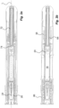
- the medicament delivery device shown in the drawings comprises a generally tubular elongated housing 10 having a distal end 12 and a proximal end 14, Fig. 1 .
- the housing 10 is further arranged with windows or openings 16, through which a medicament container 18 can be viewed.
- the medicament container 18 is arranged with a movable stopper 20.
- the device further comprises a medicament container holder 22 having a generally tubular shape, Fig. 1 .
- the medicament container holder 22 is arranged to accommodate the medicament container 18, where the medicament container 18 has a proximal end on which a medicament delivery member 24, Fig. 2 , is arranged, either made integral or connectable to the medicament container 18.
- the medicament delivery member 24 is preferably protected before use by a medicament delivery member shield 26 that in the embodiment shown is a so called rigid needle shield or RNS. It is however to be understood that other types of medicament delivery member shields may be used in order to obtain the desired protection of the medicament delivery member 24.
- the proximal end of the housing is arranged with a central passage 28, Fig. 1 , through which an activator 30 extends.
- the activator 30 is a generally tubular medicament delivery member guard.
- the medicament delivery member guard 30 is in this embodiment an activation mechanism of a drive mechanism comprised in the medicament delivery device. It is arranged slidable i.e. linearly movable in relation to the housing 10 such that the housing 10 with the medicament container 18 and the medicament delivery member 24 are moved in the proximal direction when the medicament delivery device is pressed against a dose delivery site, thereby exposing the medicament delivery member 24 such that a penetration is performed when the medicament delivery member is an injection needle.
- the activator 30 comprises a proximal tubular 32 part and two distally directed arms 34 extending from the tubular part 32.
- a medicament delivery member guard spring 35 is arranged between a distally directed circumferential wall part of the activator 30 and a proximally directed circumferential surface of the housing.
- the arms 34 are arranged slidable along the medicament container holder 22.
- inwardly directed protrusions 36 are arranged.
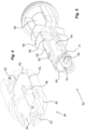
- the protrusions 36 are arranged to operably interact with a rotator 38, Figs. 3 and 4 , of a drive mechanism comprised in the medicament delivery device, when the activator30 is moved in relation to the housing, wherein the rotator 38 is positioned distally of the medicament container 18.
- the rotator 38 has a generally tubular shape and is arranged with guide ridges 42, Fig. 4 , that are intended to cooperate with the protrusions 36 of the activator 30.
- the guide ridges comprise a first guide ridge 42 i that is inclined in relation to the longitudinal axis L of the device, which inclined first guide ridge interconnects with a rounded second guide ridge 42 r as seen in Fig. 4 where the second guide ridge 42 r is generally transversal to the longitudinal axis L.
- a third guide ridge 42 l is connected to the second guide ridge, where the third guide ridge 42 l is extending in the longitudinal direction. The functions of the guide ridges will be described below.
- proximally directed tongues 44 Adjacent the third guide ridge 42 l are proximally directed tongues 44, which tongues 44 are arranged with wedge-shaped outwardly directed ledges 46.
- the rotator is arranged with cut-outs 48 at its distal end surface. Inside the rotator, support surfaces 50 are arranged. Further inside the rotator 38, orientating elements in the form of longitudinal grooves 51 are arranged, from a distal end to almost the proximal end. However, the groove 51 terminates a distance from the proximal end. At the edge of the proximal end in the direction of the longitudinal groove a cut-out 53, forming a stop recess, is made.
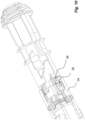
- An actuator 52 is in this embodiment a part of the drive mechanism comprised in the medicament delivery device,
- the actuator 52 is further arranged operably to the rotator 38. It comprises a first proximal tubular section 54 having a diameter slightly smaller than the inner diameter of the rotator 38. It further comprises a second section 56 arranged to fit into and to be attached to a distal part of the housing 10.
- the second section 56 is provided with proximally directed ledges 58 arranged to interact with the rotator as will be described.
- the second section is further arranged with proximally directed stop surfaces 59, Fig. 5 .
- the first section 54 is further arranged with holding members 60 which in the present embodiments are proximally extending arms that are arranged flexible in a generally radial direction.
- the free ends of the holding members 60 have outwardly extending protrusions 62 that are to interact with the guide surfaces 50 of the rotator 38 as will be described.
- the free ends of the holding members 60 are arranged with inwardly extending protrusions 64, which protrusions 64 are intended to interact with recesses 66 on a generally tubular plunger rod 68, Fig. 3 .
- the generally tubular plunger rod 68 is in this embodiment a part of the drive mechanism comprised in the medicament delivery device.
- the protrusions 64 extend into a central passage 70 of the actuator 52, in which passage 70 the plunger rod 68 fits. Further, outwardly directed, generally wedge-shaped, protrusions 71 are arranged adjacent the passage 70.
- a drive spring 72 which is in this embodiment a part of the drive mechanism comprised in the medicament delivery device, is placed inside a cavity of the hollow plunger rod 68, wherein the drive spring 72 is positioned with a proximal end thereof in contact with an end wall 74 of the plunger rod 68, Fig. 2 .
- the distal end of the drive spring 72 is in contact with a generally U-shaped element, hereafter named activator 76, having a base 78 and two arms 80, Fig. 3 .
- the arms 80 of the activator 76 are directed in the proximal direction along, and in contact with, the outer surface of the plunger rod 68, wherein the free ends of the arms 80 are arranged with generally radially outwardly directed ledges 82.
- These ledges 82 are arranged to be in contact with a proximally directed surface 84, Fig. 5 , surrounding the central passage 70 of the actuator 52.
- the medicament delivery device is further arranged with a protective cap 86, Figs. 1 and 2 , having a shape as to be releasibly attached to the proximal end of the housing.
- the protective cap 86 is further arranged with a medicament delivery member shield remover 88 that in the embodiment shown has a generally tubular shape with a diameter so as to extend into the activator and surround the medicament delivery member shield 26.
- the medicament delivery member shield remover 88 is arranged with grip elements 90 that are inwardly inclined, proximally directed tongues that are capable of gripping into the surface of the medicament delivery member shield when the protective cap is pulled in the proximal direction in relation to the medicament delivery device.
- the device is intended to function as follows.
- a medicament container 18 with an attached medicament delivery member shield 26 has been placed in the medicament container holder 22 and a protective cap has been attached to the proximal end of the medicament delivery device.
- the drive spring 72 has been tensioned in that the plunger rod 68 has been pushed distally relative the actuator 52 such that the inwardly directed protrusions 64 of the holding members 60 of the actuator 52 engage with the recesses 66 of the plunger rod 68, thereby holding the plunger rod 68.
- the rotator 38 is then pushed axially onto the actuator 52 from the proximal end.
- the rotator 38 is held such that the orientating elements, i.e. the protrusions 71, will fit in the longitudinal grooves 51 of the rotator 38.
- the rotator 38 is then pushed axially until the protrusions 71 fit into the cut-outs 53, which prevents pulling back of the rotator 38.
- this rotational position named first position
- the distally directed end of the rotator 38 is in contact with the ledges 58 of the actuator 52 as seen in Fig. 6 .
- the holding members 60 of the actuator 52 are now prevented from moving out of engagement by the support surfaces 50 of the rotator 38 in contact with the outwardly directed protrusions 62 of the holding members 60.
- the protective cap 86 is removed from the proximal end of the medicament delivery device by pulling it in the proximal direction. Because of the engagement of the tongues 90 with the medicament delivery member shield 26, the medicament delivery member shield 26 will also be pulled in the proximal direction, removed from the medicament delivery member 24. The proximal end of the medicament delivery device is then pressed against a dose delivery site. This causes the activator 30 to move inside and relative the housing 10.
- the turning/rotation of the rotator 38 will cause its distally directed end surface to slide along the ledges 58 as seen in Fig. 7 until the protrusions 36 have reached the second guide ridge 42 r .
- the cut-outs 48 of the rotator 38 have reached the ledges 58, Fig. 8 , so that further pushing of the activator 30 will cause the rotator 38 to move axially i.e. to be linearly displaced in the distal direction with its support surfaces sliding in relation to the outwardly directed protrusions of the arms of the actuator.
- the axial movement of the rotator 38 is stopped when its distally directed end surface abuts the proximally directed stop surface 59 of the actuator.
- the outwardly directed protrusions 62 of the holding members 60 of the actuator 52 have passed a proximal end surface of the rotator 38, Fig. 9 , and have thus moved out of contact with inner surfaces of the rotator 38.
- the holding members 60 of the actuator 52 are now free to flex outwardly, whereby the inwardly directed protrusions 64 of the holding members 60 are moved out of contact with the recesses 66 of the plunger rod 68.
- the flexing of the holding members 60 is rapid and outer surfaces of the holding members 60 will hit the rotator 38, causing an audible and tactile signal that the dose delivery sequence has started.
- the plunger rod 68 is now free to move in the proximal direction due to the force of the drive spring 72, wherein the proximal end of the plunger rod 68 acts on, and moves, the stopper 20 inside the medicament container 18 in the proximal direction such that a dose of medicament is expelled through the medicament delivery member 24.
- the plunger rod 68 When the stopper 20 has been moved by the plunger rod 68 to almost the proximal end inside the medicament container 18, the plunger rod 68 is moved out of contact with the arms 80 of the signalling element 76.
- the arms 80 of the signalling element 76 are thus free to flex inwards such that the ledges 82 are moved out of contact with the surfaces 84 of the actuator 52, and due to the force of the drive spring 72 in contact with and acting on the base 78 of the signalling element 76, the signalling element 76 will be moved suddenly in the distal direction the distance D until the distal end of the signalling element 76 hits a proximally directed end wall of the actuator, thus providing an audible and tactile signal that the dose delivery sequence is completed and that it is safe to remove the medicament delivery device. It may now be discarded in a safe manner.
Landscapes
- Health & Medical Sciences (AREA)
- Vascular Medicine (AREA)
- Engineering & Computer Science (AREA)
- Anesthesiology (AREA)
- Biomedical Technology (AREA)
- Heart & Thoracic Surgery (AREA)
- Hematology (AREA)
- Life Sciences & Earth Sciences (AREA)
- Animal Behavior & Ethology (AREA)
- General Health & Medical Sciences (AREA)
- Public Health (AREA)
- Veterinary Medicine (AREA)
- Infusion, Injection, And Reservoir Apparatuses (AREA)
Applications Claiming Priority (2)
| Application Number | Priority Date | Filing Date | Title |
|---|---|---|---|
| SE1550496 | 2015-04-24 | ||
| PCT/EP2016/057342 WO2016169756A1 (en) | 2015-04-24 | 2016-04-04 | Drive mechanism for an autoinjector |
Publications (2)
| Publication Number | Publication Date |
|---|---|
| EP3285832A1 EP3285832A1 (en) | 2018-02-28 |
| EP3285832B1 true EP3285832B1 (en) | 2025-03-05 |
Family
ID=55802341
Family Applications (1)
| Application Number | Title | Priority Date | Filing Date |
|---|---|---|---|
| EP16717582.7A Active EP3285832B1 (en) | 2015-04-24 | 2016-04-04 | Drive mechanism for an autoinjector |
Country Status (7)
Families Citing this family (12)
| Publication number | Priority date | Publication date | Assignee | Title |
|---|---|---|---|---|
| EP2399635A1 (en) | 2010-06-28 | 2011-12-28 | Sanofi-Aventis Deutschland GmbH | Auto-injector |
| US20210093796A1 (en) * | 2019-09-30 | 2021-04-01 | Amgen Inc. | Drug delivery device |
| US20220387719A1 (en) * | 2019-12-05 | 2022-12-08 | Shl Medical Ag | Feedback mechanisms |
| JP2023536501A (ja) * | 2020-08-07 | 2023-08-25 | サノフイ | 薬物送達デバイスのための装置 |
| CN118302212A (zh) * | 2021-12-07 | 2024-07-05 | 艾斯曲尔医疗公司 | 药剂输送装置的子组件 |
| WO2023151952A1 (en) * | 2022-02-08 | 2023-08-17 | Shl Medical Ag | A subassembly of a medicament delivery device |
| EP4551277A1 (en) * | 2022-07-07 | 2025-05-14 | SHL Medical AG | A sub-assembly of a medicament delivery device |
| CN119522115A (zh) * | 2022-07-26 | 2025-02-25 | 艾斯曲尔医疗公司 | 用于药剂递送装置的盖 |
| KR102682087B1 (ko) * | 2023-03-08 | 2024-07-05 | 주식회사 비에스엘 | 자동 약물 주입 장치 |
| KR102694740B1 (ko) * | 2023-03-29 | 2024-08-14 | 주식회사 비에스엘 | 자동 약물 주입 장치 |
| EP4494675A1 (en) | 2023-07-20 | 2025-01-22 | Ypsomed AG | A release mechanism for an injection device |
| CN119455191B (zh) * | 2024-12-27 | 2025-06-10 | 巨翊科技(上海)有限公司 | 一种针头隐匿锁止结构及注射器 |
Family Cites Families (9)
| Publication number | Priority date | Publication date | Assignee | Title |
|---|---|---|---|---|
| GB2414402B (en) * | 2004-05-28 | 2009-04-22 | Cilag Ag Int | Injection device |
| WO2008151241A2 (en) * | 2007-06-04 | 2008-12-11 | Becton, Dickinson And Company | Stopper and plunger rod for a pre-filled syringe |
| EP2583710B1 (en) * | 2010-03-31 | 2021-11-10 | SHL Medical AG | Medicament delivery device comprising feedback signalling means |
| BR112012033606A2 (pt) * | 2010-07-02 | 2019-09-24 | Carebay Holding Ltd Company No 681498 | dispositivo de distribuição de solução de hormônio de estímulo de folículo livre de preservativos |
| GB201020472D0 (en) * | 2010-12-02 | 2011-01-19 | Oval Medical Technologies Ltd | A drive assembly for an autoinjector |
| AU2012205867B2 (en) * | 2011-01-11 | 2015-01-22 | Shl Group Ab | Medicament delivery device |
| KR101544662B1 (ko) * | 2011-04-05 | 2015-08-17 | 에스에이치엘 그룹 에이비 | 레버를 갖는 로킹 기구를 포함하는 약물 전달 장치 |
| CH705345A2 (de) * | 2011-08-04 | 2013-02-15 | Tecpharma Licensing Ag | Injektionsvorrichtung mit Nadelschutzeinrichtung. |
| EP4364767A3 (en) * | 2015-04-24 | 2024-08-07 | SHL Medical AG | Sub-assembly of a medicament delivery device and a medicament delivery device |
-
2016
- 2016-04-04 CN CN201680028458.5A patent/CN107635603B/zh active Active
- 2016-04-04 KR KR1020177033851A patent/KR102016829B1/ko active Active
- 2016-04-04 WO PCT/EP2016/057342 patent/WO2016169756A1/en active Application Filing
- 2016-04-04 JP JP2017555544A patent/JP6567687B2/ja active Active
- 2016-04-04 US US15/568,816 patent/US10881797B2/en active Active
- 2016-04-04 EP EP16717582.7A patent/EP3285832B1/en active Active
- 2016-04-12 TW TW105111382A patent/TWI630936B/zh active
Also Published As
| Publication number | Publication date |
|---|---|
| US20180104415A1 (en) | 2018-04-19 |
| KR102016829B1 (ko) | 2019-08-30 |
| EP3285832A1 (en) | 2018-02-28 |
| KR20170139636A (ko) | 2017-12-19 |
| CN107635603B (zh) | 2020-09-01 |
| CN107635603A (zh) | 2018-01-26 |
| TWI630936B (zh) | 2018-08-01 |
| JP6567687B2 (ja) | 2019-08-28 |
| TW201707739A (zh) | 2017-03-01 |
| US10881797B2 (en) | 2021-01-05 |
| JP2018512973A (ja) | 2018-05-24 |
| WO2016169756A1 (en) | 2016-10-27 |
Similar Documents
| Publication | Publication Date | Title |
|---|---|---|
| EP3285832B1 (en) | Drive mechanism for an autoinjector | |
| US11484667B2 (en) | Medicament delivery device | |
| US20250041537A1 (en) | Injection device with cammed ram assembly | |
| EP2665503B1 (en) | Medicament delivery device | |
| CN109689131B (zh) | 药剂递送设备 | |
| EP3389746B1 (en) | Medicament delivery device | |
| KR101976299B1 (ko) | 투여량 설정 기구 및 투여량 설정 기구를 포함하는 약물 송달 장치 | |
| EP3102263B1 (en) | Sheath removal mechanism | |
| ES2964961T3 (es) | Dispositivo de inyección asistida para inyectar selectivamente una composición contenida en un contenedor médico | |
| EP3423131B1 (en) | Automatic delivery device with end of injection indication device | |
| US11400228B2 (en) | Medicament delivery device |
Legal Events
| Date | Code | Title | Description |
|---|---|---|---|
| STAA | Information on the status of an ep patent application or granted ep patent |
Free format text: STATUS: THE INTERNATIONAL PUBLICATION HAS BEEN MADE |
|
| PUAI | Public reference made under article 153(3) epc to a published international application that has entered the european phase |
Free format text: ORIGINAL CODE: 0009012 |
|
| STAA | Information on the status of an ep patent application or granted ep patent |
Free format text: STATUS: REQUEST FOR EXAMINATION WAS MADE |
|
| 17P | Request for examination filed |
Effective date: 20171011 |
|
| AK | Designated contracting states |
Kind code of ref document: A1 Designated state(s): AL AT BE BG CH CY CZ DE DK EE ES FI FR GB GR HR HU IE IS IT LI LT LU LV MC MK MT NL NO PL PT RO RS SE SI SK SM TR |
|
| AX | Request for extension of the european patent |
Extension state: BA ME |
|
| DAV | Request for validation of the european patent (deleted) | ||
| DAX | Request for extension of the european patent (deleted) | ||
| RAP1 | Party data changed (applicant data changed or rights of an application transferred) |
Owner name: SHL MEDICAL AG |
|
| STAA | Information on the status of an ep patent application or granted ep patent |
Free format text: STATUS: EXAMINATION IS IN PROGRESS |
|
| 17Q | First examination report despatched |
Effective date: 20210422 |
|
| STAA | Information on the status of an ep patent application or granted ep patent |
Free format text: STATUS: EXAMINATION IS IN PROGRESS |
|
| P01 | Opt-out of the competence of the unified patent court (upc) registered |
Effective date: 20230425 |
|
| GRAP | Despatch of communication of intention to grant a patent |
Free format text: ORIGINAL CODE: EPIDOSNIGR1 |
|
| STAA | Information on the status of an ep patent application or granted ep patent |
Free format text: STATUS: GRANT OF PATENT IS INTENDED |
|
| INTG | Intention to grant announced |
Effective date: 20241017 |
|
| GRAS | Grant fee paid |
Free format text: ORIGINAL CODE: EPIDOSNIGR3 |
|
| GRAA | (expected) grant |
Free format text: ORIGINAL CODE: 0009210 |
|
| STAA | Information on the status of an ep patent application or granted ep patent |
Free format text: STATUS: THE PATENT HAS BEEN GRANTED |
|
| AK | Designated contracting states |
Kind code of ref document: B1 Designated state(s): AL AT BE BG CH CY CZ DE DK EE ES FI FR GB GR HR HU IE IS IT LI LT LU LV MC MK MT NL NO PL PT RO RS SE SI SK SM TR |
|
| REG | Reference to a national code |
Ref country code: GB Ref legal event code: FG4D |
|
| REG | Reference to a national code |
Ref country code: CH Ref legal event code: EP |
|
| REG | Reference to a national code |
Ref country code: DE Ref legal event code: R096 Ref document number: 602016091437 Country of ref document: DE |
|
| REG | Reference to a national code |
Ref country code: IE Ref legal event code: FG4D |
|
| PG25 | Lapsed in a contracting state [announced via postgrant information from national office to epo] |
Ref country code: RS Free format text: LAPSE BECAUSE OF FAILURE TO SUBMIT A TRANSLATION OF THE DESCRIPTION OR TO PAY THE FEE WITHIN THE PRESCRIBED TIME-LIMIT Effective date: 20250605 |
|
| PG25 | Lapsed in a contracting state [announced via postgrant information from national office to epo] |
Ref country code: FI Free format text: LAPSE BECAUSE OF FAILURE TO SUBMIT A TRANSLATION OF THE DESCRIPTION OR TO PAY THE FEE WITHIN THE PRESCRIBED TIME-LIMIT Effective date: 20250305 |
|
| PGFP | Annual fee paid to national office [announced via postgrant information from national office to epo] |
Ref country code: DE Payment date: 20250428 Year of fee payment: 10 |
|
| REG | Reference to a national code |
Ref country code: NL Ref legal event code: MP Effective date: 20250305 |
|
| PG25 | Lapsed in a contracting state [announced via postgrant information from national office to epo] |
Ref country code: ES Free format text: LAPSE BECAUSE OF FAILURE TO SUBMIT A TRANSLATION OF THE DESCRIPTION OR TO PAY THE FEE WITHIN THE PRESCRIBED TIME-LIMIT Effective date: 20250305 |
|
| PGFP | Annual fee paid to national office [announced via postgrant information from national office to epo] |
Ref country code: GB Payment date: 20250422 Year of fee payment: 10 |
|
| REG | Reference to a national code |
Ref country code: LT Ref legal event code: MG9D |
|
| PG25 | Lapsed in a contracting state [announced via postgrant information from national office to epo] |
Ref country code: NO Free format text: LAPSE BECAUSE OF FAILURE TO SUBMIT A TRANSLATION OF THE DESCRIPTION OR TO PAY THE FEE WITHIN THE PRESCRIBED TIME-LIMIT Effective date: 20250605 |
|
| PG25 | Lapsed in a contracting state [announced via postgrant information from national office to epo] |
Ref country code: HR Free format text: LAPSE BECAUSE OF FAILURE TO SUBMIT A TRANSLATION OF THE DESCRIPTION OR TO PAY THE FEE WITHIN THE PRESCRIBED TIME-LIMIT Effective date: 20250305 |
|
| PG25 | Lapsed in a contracting state [announced via postgrant information from national office to epo] |
Ref country code: LV Free format text: LAPSE BECAUSE OF FAILURE TO SUBMIT A TRANSLATION OF THE DESCRIPTION OR TO PAY THE FEE WITHIN THE PRESCRIBED TIME-LIMIT Effective date: 20250305 |
|
| PGFP | Annual fee paid to national office [announced via postgrant information from national office to epo] |
Ref country code: FR Payment date: 20250424 Year of fee payment: 10 |
|
| PG25 | Lapsed in a contracting state [announced via postgrant information from national office to epo] |
Ref country code: GR Free format text: LAPSE BECAUSE OF FAILURE TO SUBMIT A TRANSLATION OF THE DESCRIPTION OR TO PAY THE FEE WITHIN THE PRESCRIBED TIME-LIMIT Effective date: 20250606 Ref country code: BG Free format text: LAPSE BECAUSE OF FAILURE TO SUBMIT A TRANSLATION OF THE DESCRIPTION OR TO PAY THE FEE WITHIN THE PRESCRIBED TIME-LIMIT Effective date: 20250305 |
|
| PGFP | Annual fee paid to national office [announced via postgrant information from national office to epo] |
Ref country code: CH Payment date: 20250501 Year of fee payment: 10 |
|
| REG | Reference to a national code |
Ref country code: AT Ref legal event code: MK05 Ref document number: 1772345 Country of ref document: AT Kind code of ref document: T Effective date: 20250305 |
|
| PG25 | Lapsed in a contracting state [announced via postgrant information from national office to epo] |
Ref country code: NL Free format text: LAPSE BECAUSE OF FAILURE TO SUBMIT A TRANSLATION OF THE DESCRIPTION OR TO PAY THE FEE WITHIN THE PRESCRIBED TIME-LIMIT Effective date: 20250305 |