EP3285686B1 - Methods for anatomic mapping for prosthetic implants - Google Patents
Methods for anatomic mapping for prosthetic implants Download PDFInfo
- Publication number
- EP3285686B1 EP3285686B1 EP16723572.0A EP16723572A EP3285686B1 EP 3285686 B1 EP3285686 B1 EP 3285686B1 EP 16723572 A EP16723572 A EP 16723572A EP 3285686 B1 EP3285686 B1 EP 3285686B1
- Authority
- EP
- European Patent Office
- Prior art keywords
- patient
- anatomy
- digital representation
- stent graft
- imaging data
- Prior art date
- Legal status (The legal status is an assumption and is not a legal conclusion. Google has not performed a legal analysis and makes no representation as to the accuracy of the status listed.)
- Active
Links
- 238000000034 method Methods 0.000 title claims description 107
- 239000007943 implant Substances 0.000 title claims description 9
- 238000013507 mapping Methods 0.000 title description 4
- 210000003484 anatomy Anatomy 0.000 claims description 115
- 238000003384 imaging method Methods 0.000 claims description 92
- 210000000702 aorta abdominal Anatomy 0.000 claims description 24
- 238000003780 insertion Methods 0.000 claims description 18
- 230000037431 insertion Effects 0.000 claims description 18
- 210000004204 blood vessel Anatomy 0.000 claims description 12
- 230000004044 response Effects 0.000 claims description 7
- 210000000709 aorta Anatomy 0.000 description 92
- 210000002254 renal artery Anatomy 0.000 description 35
- 239000000463 material Substances 0.000 description 31
- 238000002591 computed tomography Methods 0.000 description 27
- 230000008569 process Effects 0.000 description 19
- 230000015654 memory Effects 0.000 description 17
- 208000007474 aortic aneurysm Diseases 0.000 description 15
- 230000008439 repair process Effects 0.000 description 15
- 210000005166 vasculature Anatomy 0.000 description 15
- 208000002223 abdominal aortic aneurysm Diseases 0.000 description 13
- 238000012986 modification Methods 0.000 description 13
- 230000004048 modification Effects 0.000 description 13
- 230000011218 segmentation Effects 0.000 description 12
- 239000008280 blood Substances 0.000 description 11
- 210000004369 blood Anatomy 0.000 description 11
- 210000002434 celiac artery Anatomy 0.000 description 11
- 210000001363 mesenteric artery superior Anatomy 0.000 description 11
- 238000012545 processing Methods 0.000 description 10
- 238000012549 training Methods 0.000 description 10
- 230000002792 vascular Effects 0.000 description 10
- 208000004434 Calcinosis Diseases 0.000 description 9
- 230000008859 change Effects 0.000 description 9
- 206010002329 Aneurysm Diseases 0.000 description 8
- 239000003550 marker Substances 0.000 description 8
- 238000005259 measurement Methods 0.000 description 8
- 229910052751 metal Inorganic materials 0.000 description 7
- 239000002184 metal Substances 0.000 description 7
- 238000002600 positron emission tomography Methods 0.000 description 7
- 230000003466 anti-cipated effect Effects 0.000 description 6
- 238000004422 calculation algorithm Methods 0.000 description 6
- 238000004891 communication Methods 0.000 description 6
- 238000011960 computer-aided design Methods 0.000 description 6
- 238000002716 delivery method Methods 0.000 description 6
- 239000004744 fabric Substances 0.000 description 6
- -1 poly(vinyl imidazole) Polymers 0.000 description 6
- 239000007787 solid Substances 0.000 description 6
- 238000002604 ultrasonography Methods 0.000 description 6
- 210000001367 artery Anatomy 0.000 description 5
- 230000006870 function Effects 0.000 description 5
- 238000002595 magnetic resonance imaging Methods 0.000 description 5
- 238000004519 manufacturing process Methods 0.000 description 5
- 238000004458 analytical method Methods 0.000 description 4
- 239000000560 biocompatible material Substances 0.000 description 4
- 239000011248 coating agent Substances 0.000 description 4
- 238000000576 coating method Methods 0.000 description 4
- 238000011961 computed axial tomography Methods 0.000 description 4
- 238000001514 detection method Methods 0.000 description 4
- 238000010191 image analysis Methods 0.000 description 4
- 150000002739 metals Chemical class 0.000 description 4
- 229920001343 polytetrafluoroethylene Polymers 0.000 description 4
- 239000004810 polytetrafluoroethylene Substances 0.000 description 4
- 238000002603 single-photon emission computed tomography Methods 0.000 description 4
- 238000012800 visualization Methods 0.000 description 4
- 238000004364 calculation method Methods 0.000 description 3
- 238000011156 evaluation Methods 0.000 description 3
- 239000012530 fluid Substances 0.000 description 3
- 210000003090 iliac artery Anatomy 0.000 description 3
- 238000003709 image segmentation Methods 0.000 description 3
- 229910001092 metal group alloy Inorganic materials 0.000 description 3
- 239000000203 mixture Substances 0.000 description 3
- 230000002093 peripheral effect Effects 0.000 description 3
- 229920000642 polymer Polymers 0.000 description 3
- 230000029058 respiratory gaseous exchange Effects 0.000 description 3
- 230000007704 transition Effects 0.000 description 3
- XEEYBQQBJWHFJM-UHFFFAOYSA-N Iron Chemical compound [Fe] XEEYBQQBJWHFJM-UHFFFAOYSA-N 0.000 description 2
- PXHVJJICTQNCMI-UHFFFAOYSA-N Nickel Chemical compound [Ni] PXHVJJICTQNCMI-UHFFFAOYSA-N 0.000 description 2
- 208000007536 Thrombosis Diseases 0.000 description 2
- 230000003187 abdominal effect Effects 0.000 description 2
- 230000003143 atherosclerotic effect Effects 0.000 description 2
- 230000036760 body temperature Effects 0.000 description 2
- 230000002308 calcification Effects 0.000 description 2
- 230000008021 deposition Effects 0.000 description 2
- 238000011161 development Methods 0.000 description 2
- 230000018109 developmental process Effects 0.000 description 2
- 201000010099 disease Diseases 0.000 description 2
- 208000037265 diseases, disorders, signs and symptoms Diseases 0.000 description 2
- 210000001105 femoral artery Anatomy 0.000 description 2
- 238000002594 fluoroscopy Methods 0.000 description 2
- PCHJSUWPFVWCPO-UHFFFAOYSA-N gold Chemical compound [Au] PCHJSUWPFVWCPO-UHFFFAOYSA-N 0.000 description 2
- 229910052737 gold Inorganic materials 0.000 description 2
- 239000010931 gold Substances 0.000 description 2
- 230000010354 integration Effects 0.000 description 2
- 210000003141 lower extremity Anatomy 0.000 description 2
- 238000010801 machine learning Methods 0.000 description 2
- 238000013178 mathematical model Methods 0.000 description 2
- 230000007246 mechanism Effects 0.000 description 2
- 210000004249 mesenteric artery inferior Anatomy 0.000 description 2
- 230000003562 morphometric effect Effects 0.000 description 2
- 238000013425 morphometry Methods 0.000 description 2
- 230000003287 optical effect Effects 0.000 description 2
- BASFCYQUMIYNBI-UHFFFAOYSA-N platinum Chemical compound [Pt] BASFCYQUMIYNBI-UHFFFAOYSA-N 0.000 description 2
- 229920000139 polyethylene terephthalate Polymers 0.000 description 2
- 239000005020 polyethylene terephthalate Substances 0.000 description 2
- 230000001902 propagating effect Effects 0.000 description 2
- 238000000110 selective laser sintering Methods 0.000 description 2
- XLYOFNOQVPJJNP-UHFFFAOYSA-N water Substances O XLYOFNOQVPJJNP-UHFFFAOYSA-N 0.000 description 2
- OYPRJOBELJOOCE-UHFFFAOYSA-N Calcium Chemical compound [Ca] OYPRJOBELJOOCE-UHFFFAOYSA-N 0.000 description 1
- VYZAMTAEIAYCRO-UHFFFAOYSA-N Chromium Chemical compound [Cr] VYZAMTAEIAYCRO-UHFFFAOYSA-N 0.000 description 1
- RYGMFSIKBFXOCR-UHFFFAOYSA-N Copper Chemical compound [Cu] RYGMFSIKBFXOCR-UHFFFAOYSA-N 0.000 description 1
- 229920004934 Dacron® Polymers 0.000 description 1
- 208000031481 Pathologic Constriction Diseases 0.000 description 1
- 229920003171 Poly (ethylene oxide) Polymers 0.000 description 1
- 239000004793 Polystyrene Substances 0.000 description 1
- 229910001069 Ti alloy Inorganic materials 0.000 description 1
- ATJFFYVFTNAWJD-UHFFFAOYSA-N Tin Chemical compound [Sn] ATJFFYVFTNAWJD-UHFFFAOYSA-N 0.000 description 1
- RTAQQCXQSZGOHL-UHFFFAOYSA-N Titanium Chemical compound [Ti] RTAQQCXQSZGOHL-UHFFFAOYSA-N 0.000 description 1
- 210000001015 abdomen Anatomy 0.000 description 1
- 230000002159 abnormal effect Effects 0.000 description 1
- 125000002252 acyl group Chemical group 0.000 description 1
- 239000000654 additive Substances 0.000 description 1
- 230000000996 additive effect Effects 0.000 description 1
- 239000000853 adhesive Substances 0.000 description 1
- 230000001070 adhesive effect Effects 0.000 description 1
- 229910045601 alloy Inorganic materials 0.000 description 1
- 239000000956 alloy Substances 0.000 description 1
- 238000004873 anchoring Methods 0.000 description 1
- 210000002376 aorta thoracic Anatomy 0.000 description 1
- 238000013459 approach Methods 0.000 description 1
- 230000005540 biological transmission Effects 0.000 description 1
- 230000015572 biosynthetic process Effects 0.000 description 1
- 230000017531 blood circulation Effects 0.000 description 1
- 229910052791 calcium Inorganic materials 0.000 description 1
- 239000011575 calcium Substances 0.000 description 1
- 229920002301 cellulose acetate Polymers 0.000 description 1
- 239000000919 ceramic Substances 0.000 description 1
- 238000006243 chemical reaction Methods 0.000 description 1
- 229910052804 chromium Inorganic materials 0.000 description 1
- 239000011651 chromium Substances 0.000 description 1
- 238000013170 computed tomography imaging Methods 0.000 description 1
- 238000004590 computer program Methods 0.000 description 1
- 229920001577 copolymer Polymers 0.000 description 1
- 229910052802 copper Inorganic materials 0.000 description 1
- 239000010949 copper Substances 0.000 description 1
- 230000002950 deficient Effects 0.000 description 1
- 238000002059 diagnostic imaging Methods 0.000 description 1
- 230000010339 dilation Effects 0.000 description 1
- 238000006073 displacement reaction Methods 0.000 description 1
- 238000003708 edge detection Methods 0.000 description 1
- 230000000694 effects Effects 0.000 description 1
- 239000013013 elastic material Substances 0.000 description 1
- 239000011888 foil Substances 0.000 description 1
- 230000004927 fusion Effects 0.000 description 1
- 230000036541 health Effects 0.000 description 1
- 238000002513 implantation Methods 0.000 description 1
- 230000002452 interceptive effect Effects 0.000 description 1
- 229910052742 iron Inorganic materials 0.000 description 1
- 230000001788 irregular Effects 0.000 description 1
- 210000003734 kidney Anatomy 0.000 description 1
- 238000013508 migration Methods 0.000 description 1
- 230000005012 migration Effects 0.000 description 1
- 230000000877 morphologic effect Effects 0.000 description 1
- 210000000653 nervous system Anatomy 0.000 description 1
- 229910052759 nickel Inorganic materials 0.000 description 1
- 229920001778 nylon Polymers 0.000 description 1
- 210000000056 organ Anatomy 0.000 description 1
- 238000013450 outlier detection Methods 0.000 description 1
- 239000000123 paper Substances 0.000 description 1
- 239000011505 plaster Substances 0.000 description 1
- 239000002985 plastic film Substances 0.000 description 1
- 229920006255 plastic film Polymers 0.000 description 1
- 229910052697 platinum Inorganic materials 0.000 description 1
- 229920002006 poly(N-vinylimidazole) polymer Polymers 0.000 description 1
- 229920001200 poly(ethylene-vinyl acetate) Polymers 0.000 description 1
- 229920000058 polyacrylate Polymers 0.000 description 1
- 239000004417 polycarbonate Substances 0.000 description 1
- 229920000515 polycarbonate Polymers 0.000 description 1
- 229920000728 polyester Polymers 0.000 description 1
- 229920000098 polyolefin Polymers 0.000 description 1
- 229920002223 polystyrene Polymers 0.000 description 1
- 229920002635 polyurethane Polymers 0.000 description 1
- 239000004814 polyurethane Substances 0.000 description 1
- 239000004800 polyvinyl chloride Substances 0.000 description 1
- 229920000915 polyvinyl chloride Polymers 0.000 description 1
- 229920002620 polyvinyl fluoride Polymers 0.000 description 1
- 238000003672 processing method Methods 0.000 description 1
- 230000008707 rearrangement Effects 0.000 description 1
- 230000009467 reduction Effects 0.000 description 1
- 239000012858 resilient material Substances 0.000 description 1
- 238000012552 review Methods 0.000 description 1
- 239000010979 ruby Substances 0.000 description 1
- 229910001750 ruby Inorganic materials 0.000 description 1
- 229910001220 stainless steel Inorganic materials 0.000 description 1
- 239000010935 stainless steel Substances 0.000 description 1
- 230000036262 stenosis Effects 0.000 description 1
- 208000037804 stenosis Diseases 0.000 description 1
- 239000000126 substance Substances 0.000 description 1
- XTHPWXDJESJLNJ-UHFFFAOYSA-N sulfurochloridic acid Chemical compound OS(Cl)(=O)=O XTHPWXDJESJLNJ-UHFFFAOYSA-N 0.000 description 1
- 238000001356 surgical procedure Methods 0.000 description 1
- 230000008961 swelling Effects 0.000 description 1
- 229920001169 thermoplastic Polymers 0.000 description 1
- 239000004416 thermosoftening plastic Substances 0.000 description 1
- 229910052718 tin Inorganic materials 0.000 description 1
- 239000011135 tin Substances 0.000 description 1
- 239000010936 titanium Substances 0.000 description 1
- 229910052719 titanium Inorganic materials 0.000 description 1
- 238000012876 topography Methods 0.000 description 1
- 238000011144 upstream manufacturing Methods 0.000 description 1
- 230000000007 visual effect Effects 0.000 description 1
Images


Classifications
-
- A—HUMAN NECESSITIES
- A61—MEDICAL OR VETERINARY SCIENCE; HYGIENE
- A61F—FILTERS IMPLANTABLE INTO BLOOD VESSELS; PROSTHESES; DEVICES PROVIDING PATENCY TO, OR PREVENTING COLLAPSING OF, TUBULAR STRUCTURES OF THE BODY, e.g. STENTS; ORTHOPAEDIC, NURSING OR CONTRACEPTIVE DEVICES; FOMENTATION; TREATMENT OR PROTECTION OF EYES OR EARS; BANDAGES, DRESSINGS OR ABSORBENT PADS; FIRST-AID KITS
- A61F2/00—Filters implantable into blood vessels; Prostheses, i.e. artificial substitutes or replacements for parts of the body; Appliances for connecting them with the body; Devices providing patency to, or preventing collapsing of, tubular structures of the body, e.g. stents
- A61F2/02—Prostheses implantable into the body
- A61F2/04—Hollow or tubular parts of organs, e.g. bladders, tracheae, bronchi or bile ducts
- A61F2/06—Blood vessels
- A61F2/07—Stent-grafts
-
- A—HUMAN NECESSITIES
- A61—MEDICAL OR VETERINARY SCIENCE; HYGIENE
- A61B—DIAGNOSIS; SURGERY; IDENTIFICATION
- A61B34/00—Computer-aided surgery; Manipulators or robots specially adapted for use in surgery
- A61B34/10—Computer-aided planning, simulation or modelling of surgical operations
-
- G—PHYSICS
- G06—COMPUTING; CALCULATING OR COUNTING
- G06T—IMAGE DATA PROCESSING OR GENERATION, IN GENERAL
- G06T3/00—Geometric image transformations in the plane of the image
- G06T3/10—Selection of transformation methods according to the characteristics of the input images
-
- G—PHYSICS
- G06—COMPUTING; CALCULATING OR COUNTING
- G06T—IMAGE DATA PROCESSING OR GENERATION, IN GENERAL
- G06T7/00—Image analysis
- G06T7/0002—Inspection of images, e.g. flaw detection
- G06T7/0012—Biomedical image inspection
-
- G—PHYSICS
- G06—COMPUTING; CALCULATING OR COUNTING
- G06T—IMAGE DATA PROCESSING OR GENERATION, IN GENERAL
- G06T7/00—Image analysis
- G06T7/60—Analysis of geometric attributes
-
- A—HUMAN NECESSITIES
- A61—MEDICAL OR VETERINARY SCIENCE; HYGIENE
- A61B—DIAGNOSIS; SURGERY; IDENTIFICATION
- A61B34/00—Computer-aided surgery; Manipulators or robots specially adapted for use in surgery
- A61B34/10—Computer-aided planning, simulation or modelling of surgical operations
- A61B2034/108—Computer aided selection or customisation of medical implants or cutting guides
-
- A—HUMAN NECESSITIES
- A61—MEDICAL OR VETERINARY SCIENCE; HYGIENE
- A61F—FILTERS IMPLANTABLE INTO BLOOD VESSELS; PROSTHESES; DEVICES PROVIDING PATENCY TO, OR PREVENTING COLLAPSING OF, TUBULAR STRUCTURES OF THE BODY, e.g. STENTS; ORTHOPAEDIC, NURSING OR CONTRACEPTIVE DEVICES; FOMENTATION; TREATMENT OR PROTECTION OF EYES OR EARS; BANDAGES, DRESSINGS OR ABSORBENT PADS; FIRST-AID KITS
- A61F2/00—Filters implantable into blood vessels; Prostheses, i.e. artificial substitutes or replacements for parts of the body; Appliances for connecting them with the body; Devices providing patency to, or preventing collapsing of, tubular structures of the body, e.g. stents
- A61F2/82—Devices providing patency to, or preventing collapsing of, tubular structures of the body, e.g. stents
- A61F2/86—Stents in a form characterised by the wire-like elements; Stents in the form characterised by a net-like or mesh-like structure
- A61F2/89—Stents in a form characterised by the wire-like elements; Stents in the form characterised by a net-like or mesh-like structure the wire-like elements comprising two or more adjacent rings flexibly connected by separate members
-
- A—HUMAN NECESSITIES
- A61—MEDICAL OR VETERINARY SCIENCE; HYGIENE
- A61F—FILTERS IMPLANTABLE INTO BLOOD VESSELS; PROSTHESES; DEVICES PROVIDING PATENCY TO, OR PREVENTING COLLAPSING OF, TUBULAR STRUCTURES OF THE BODY, e.g. STENTS; ORTHOPAEDIC, NURSING OR CONTRACEPTIVE DEVICES; FOMENTATION; TREATMENT OR PROTECTION OF EYES OR EARS; BANDAGES, DRESSINGS OR ABSORBENT PADS; FIRST-AID KITS
- A61F2/00—Filters implantable into blood vessels; Prostheses, i.e. artificial substitutes or replacements for parts of the body; Appliances for connecting them with the body; Devices providing patency to, or preventing collapsing of, tubular structures of the body, e.g. stents
- A61F2/02—Prostheses implantable into the body
- A61F2/04—Hollow or tubular parts of organs, e.g. bladders, tracheae, bronchi or bile ducts
- A61F2/06—Blood vessels
- A61F2002/061—Blood vessels provided with means for allowing access to secondary lumens
-
- A—HUMAN NECESSITIES
- A61—MEDICAL OR VETERINARY SCIENCE; HYGIENE
- A61F—FILTERS IMPLANTABLE INTO BLOOD VESSELS; PROSTHESES; DEVICES PROVIDING PATENCY TO, OR PREVENTING COLLAPSING OF, TUBULAR STRUCTURES OF THE BODY, e.g. STENTS; ORTHOPAEDIC, NURSING OR CONTRACEPTIVE DEVICES; FOMENTATION; TREATMENT OR PROTECTION OF EYES OR EARS; BANDAGES, DRESSINGS OR ABSORBENT PADS; FIRST-AID KITS
- A61F2240/00—Manufacturing or designing of prostheses classified in groups A61F2/00 - A61F2/26 or A61F2/82 or A61F9/00 or A61F11/00 or subgroups thereof
- A61F2240/001—Designing or manufacturing processes
- A61F2240/002—Designing or making customized prostheses
-
- A—HUMAN NECESSITIES
- A61—MEDICAL OR VETERINARY SCIENCE; HYGIENE
- A61F—FILTERS IMPLANTABLE INTO BLOOD VESSELS; PROSTHESES; DEVICES PROVIDING PATENCY TO, OR PREVENTING COLLAPSING OF, TUBULAR STRUCTURES OF THE BODY, e.g. STENTS; ORTHOPAEDIC, NURSING OR CONTRACEPTIVE DEVICES; FOMENTATION; TREATMENT OR PROTECTION OF EYES OR EARS; BANDAGES, DRESSINGS OR ABSORBENT PADS; FIRST-AID KITS
- A61F2240/00—Manufacturing or designing of prostheses classified in groups A61F2/00 - A61F2/26 or A61F2/82 or A61F9/00 or A61F11/00 or subgroups thereof
- A61F2240/001—Designing or manufacturing processes
- A61F2240/005—Templates
-
- G—PHYSICS
- G06—COMPUTING; CALCULATING OR COUNTING
- G06T—IMAGE DATA PROCESSING OR GENERATION, IN GENERAL
- G06T2207/00—Indexing scheme for image analysis or image enhancement
- G06T2207/30—Subject of image; Context of image processing
- G06T2207/30004—Biomedical image processing
- G06T2207/30048—Heart; Cardiac
-
- G—PHYSICS
- G06—COMPUTING; CALCULATING OR COUNTING
- G06T—IMAGE DATA PROCESSING OR GENERATION, IN GENERAL
- G06T2219/00—Indexing scheme for manipulating 3D models or images for computer graphics
- G06T2219/20—Indexing scheme for editing of 3D models
- G06T2219/2004—Aligning objects, relative positioning of parts
Definitions
- Prosthetic devices are often implanted into, for example, diseased portions of a patient to repair, support, stent, and/or otherwise facilitate the proper function of those diseased portions.
- prosthetic devices such as stent grafts can be used to repair diseased portions of a patient's vascular system.
- aneurysms within a patient's vascular system generally involve the abnormal swelling or dilation of a blood vessel such as an artery, which typically weakens the wall of the blood vessel making it susceptible to rupture.
- An abdominal aortic aneurysm (AAA) is a common type of aneurysm that poses a serious health threat.
- a common way to treat AAA and other types of aneurysms is to place an endovascular stent graft in the affected blood vessel such that the stent graft spans across (e.g., traverses) and extends beyond the proximal and distal ends of the diseased portion of the vasculature.
- the stent graft can thus, reline the diseased vasculature, providing an alternate blood conduit that isolates the aneurysm from the high-pressure flow of blood, thereby reducing or eliminating the risk of rupture.
- a prosthetic device can be an implant and/or mechanism, which can provide structural or functional support to a diseased and/or defective portion of the body.
- the arrangement of the anatomy can present challenges when attempting to place and/or secure a prosthetic device (including stent grafts or the like). Such challenges can result in misalignment and/or suboptimal configuration of the prosthetic device within the anatomy.
- a method of generating a patient-specific prosthetic comprising receiving anatomic imaging data representative of a portion of a patient's anatomy; defining a first digital representation of the anatomic imaging data, the first digital representation of the anatomic imaging data being associated with a portion of the patient's anatomy in a first configuration; modifying the first digital representation of the anatomic imaging data to generate a second digital representation of the anatomic imaging data, the second digital representation of the anatomic imaging data being associated with the portion of the patient's anatomy in a second configuration, the portion of the patient's anatomy being transitioned from the first configuration to the second configuration in response to insertion of a prosthetic implant; and generating a patient-specific prosthetic template of the portion of the patient's anatomy based at least in part on the second digital representation of the anatomic imaging data.
- the second digital representation of the anatomic imaging data is associated with the portion of the patient's anatomy in a second configuration, the portion of the patient's anatomy is transitioned from the first configuration to the second configuration in response to insertion of a prosthetic implant.
- a patient-specific prosthetic template of the portion of the patient's anatomy is formed based at least in part on the second digital representation of the anatomic imaging data.
- a member is intended to mean a single member or a combination of members
- a material is intended to mean one or more materials, or a combination thereof.
- proximal and distal refer to a direction closer to and away from, respectively, an operator of, for example, a medical device.
- the end of the medical device contacting the patient's body would be the distal end of the medical device, while the end opposite the distal end would be the proximal end of the medical device.
- a device such as an endovascular stent graft
- the end of the device closer to the patient's heart would be the proximal end
- the end opposite the proximal end would be the distal end.
- the proximal end of such a device can be upstream of the distal end of the device.
- polymers examples include nylons, polyesters, polycarbonates, polyacrylates, polymers of ethylene-vinyl acetates and other acyl substituted cellulose acetates, non-degradable polyurethanes, polystyrenes, polyvinyl chloride, polyvinyl fluoride, poly(vinyl imidazole), chlorosulphonate polyolefins, polyethylene oxide, polyethylene terephthalate (PET), polytetrafluoroethylene (PTFE), and/or blends and copolymers thereof.
- the embodiments described herein can be used to facilitate the function and/or the integration of a prosthetic device within a portion of a patient.
- the devices and/or methods described herein can be used in conjunction with and/or can otherwise be included endovascular repair using stent grafts.
- the embodiments are shown and described herein as being used, for example, to facilitate endovascular repair, in other embodiments, any of the devices and/or methods described herein can be used to facilitate treatment of any portion of a patient.
- the devices and methods described herein can facilitate the integration of any suitable implant, prosthetic, device, mechanism, machine, and/or the like within a portion of the body of a patient such as the patient's vascular system, nervous system, muscular-skeletal system, etc. Therefore, while the embodiments are shown and described herein as being used in the endovascular repair of an abdominal aortic aneurysm, they are presented by way of example and are not limited thereto. The scope of the invention is limited by the appended claims
- Some of the devices and/or methods described herein can be used in minimally invasive treatment techniques such as endovascular repair using stent grafts. Such repair techniques are generally preferred over traditional open surgical repair and often result in reduced morbidity or mortality rates. In some instances, however, the arrangement of the diseased vasculature can result in a need to alter a portion of the stent graft prior to insertion into the body. For example, in an endovascular repair of an abdominal aortic aneurysm, the aneurysm can be situated adjacent to and/or directly distal to normally functioning vessels branching from a portion of the aorta.
- the fenestrations or openings of the stent grafts can correspond to a size, shape, and/or relative position of, inter alia, the renal arteries.
- the fenestration process involves measurements based on medical images (such as CT scans) of the vessel origins. For example, in some instances, longitudinal distances of branch vessels can be measured and relative angular locations of the branch vessels can be estimated and/or calculated from a reference point. Based on these measurements and/or calculations, a surgeon can mark and cut the stent fabric of a stent graft to define one or more fenestrations. The fenestrated stent graft can then be positioned within the diseased vasculature (e.g., via an endovascular procedure) and oriented to substantially align the fenestrations with openings of the corresponding branch vessels.
- medical images such as CT scans
- the devices and/or methods described herein can be used to generate a template and/or model based on medical imaging data of a diseased portion of a patient's vascular system (e.g., an abdominal aortic aneurysm).
- the template can be substantially similar to those described in U.S. Patent Publication No. 2013/0296998 entitled, "Fenestration Template for Endovascular Repair of Aortic Aneurysms," filed May 1, 2013 (“the '998 publication").
- an electronic device such as a personal computer, workstation, laptop, etc. can receive the imaging data and can calculate and/or otherwise define a digital representation of the imaging data.
- the electronic device can define the template and can send a signal to an output device such as a 3-D printer or rapid prototyping device, which can then output, form, and/or 2-D or 3-D print the template.
- the template in turn, can be used to facilitate the fenestration process of a prosthetic (e.g., a stent graft).
- a prosthetic e.g., a stent graft
- the devices and/or methods described herein can be used to determine and/or calculate a change in the arrangement of a portion of the anatomy resulting from the insertion and/or indwelling of the prosthetic, and can form a template representing the portion of the anatomy thereafter, as described in further detail herein.
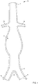
- FIGS. 1-2B illustrate a diseased portion of a patient's abdominal aorta 10. While portions of the abdominal aorta 10 are described below, the discussion of the abdominal aorta 10 is not exhaustive; rather, the discussion below provides a reference to the relevant anatomic structures.
- the abdominal aorta 10 (also referred to herein as "aorta”) has a proximal end portion 11, receiving a flow of blood from the descending aorta (not shown), and a distal end portion 12, supplying a flow of blood to the lower limbs. As shown in FIG.
- the aorta 10 at or near the proximal end portion 11 supplies a flow of blood to the left renal artery 14 and the right renal artery 13, which in turn, supply blood to the left and right kidney, respectively.
- the proximal end portion 11 of the aorta 10 also supplies a flow of blood to the superior mesenteric artery (SMA) and the celiac artery.
- SMA superior mesenteric artery
- the distal end portion 12 of the aorta 10 forms the iliac bifurcation 20, through which the aorta 10 supplies a flow of blood to the left common iliac artery 16 and the right common iliac artery 15, which in turn, supply blood to the left and right lower limbs, respectively.
- FIG. 1 the aorta 10 at or near the proximal end portion 11 supplies a flow of blood to the left renal artery 14 and the right renal artery 13, which in turn, supply blood to the left and right kidney, respectively.
- SMA superior me
- an imaging device can be a X-ray device, a computed tomography (CT) device, a computed axial tomography (CAT) device, a magnetic resonance imaging device (MRI), a magnetic resonance angiograph (MRA) device, a positron emission tomography (PET) device, a single photon emission computed tomography (SPECT) device, an ultrasound device, and/or any other suitable device for imaging a portion of the patient and/or a combination thereof (e.g., a CT/MRA device, a PET/CT device, a SPECT/CT device, etc.).
- the imaging data captured by the imaging device can thus, be used to determine salient features of the patient's aorta 10 such as, for example, the branch vessels in fluid communication with the aorta 10.
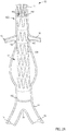
- a doctor, surgeon, technician, etc. can use the imaging data to determine and/or calculate a size, shape, position, and/or orientation of at least the renal arteries 13 and 14.
- the doctor, surgeon, technician, etc. can form and/or define one or more fenestrations 165 in the stent graft 160 associated with the determined and/or calculated characteristics of at least the renal arteries 13 and 14.
- the stiffening members 164 can be any suitable structure that can, for example, bias the stent graft 160 in an open configuration, thereby structurally supporting the stent material (also known as "stent fabric").
- the stiffening members 164 can be formed from a metal or a metal alloy such as, for example, those described above.
- such a metal or metal alloy for example, is radio-opaque and/or otherwise coated with a radio-opaque material configured to be visible using, for example, fluoroscopy.
- the stiffening members 164 can transition from a restrained or deformed delivery configuration (e.g., when disposed in a delivery catheter to an expanded and/or biased indwelling configuration, as shown in FIG. 2A .
- the stent graft 160 defines the set of fenestrations 165, as described above.
- the fenestrations 165 are each aligned with its corresponding renal artery 13 or 14 and can each have a size, shape, and/or configuration that is associated with its corresponding renal artery 13 or 14. In this manner, the fenestrations 165 can allow blood to flow from the aorta 10 and into the left renal artery 14 and the right renal artery 13 via the fenestrations 165.
- the stent graft 160 can define one or more fenestrations associated with other branch vessels stemming from the aorta 10 such as, for example, the superior mesenteric artery (SMA), the celiac artery, and/or the like.
- SMA superior mesenteric artery
- celiac artery celiac artery
- the placement and/or indwelling of the stent graft 160 within the aorta 10 can, for example, alter, shift, rotate, translate, morph, and/or otherwise reconfigured the arrangement of the patient's aorta 10.
- the openings of the renal arteries 13 and 14 are shifted relative to the fenestrations 165 defined by the stent graft 160.
- the shifting of the aorta 10 relative to the stent graft 160 results in at least a partial blockage of the renal arteries 13 and 14, as shown in FIG. 2B .
- the openings of the renal arteries 13 and 14 can be about 4 millimeters (mm) to about 7 mm, and the shifting and/or rearrangement of the aorta 10 can result in a shifting of the openings of the renal arteries 13 and 14 relative to the fenestrations 165 by about 1 mm, about 2 mm, about 3 mm, about 4 mm, about 5 mm, about 6 mm, about 7 mm, or more.
- the shifting of the aorta 10 resulting from the placement and/or indwelling of the stent graft 160 can result in a blockage of the renal arteries 13 and 14.
- the shifting of the aorta 10 can result in more than about a 1%, 5%, 10%, 20%, 30%, 40%, 50%, 60%, 70%, 80%, 90%, or 100% blockage of the renal arteries 13 and 14.
- the shifting of the aorta 10 can result in a similar misalignment of any branch vessel relative to its corresponding fenestration in the stent graft 160.
- an electronic device can be configured to determine and/or calculate the shift in the anatomy that would result from the insertion and/or indwelling of prosthetic (e.g., a stent graft) and can define one or more digital representations of the anatomy.
- the electronic device can be a personal computer (PC), a laptop, a workstation, and/or the like disposed in a central location or distributed in multiple locations.
- the electronic device can include at least a processor and a memory.
- the electronic device can also include a display and/or the like.
- the memory can be, for example, a random access memory (RAM), a memory buffer, a hard drive, a database, an erasable programmable read-only memory (EPROM), an electrically erasable read-only memory (EEPROM), a read-only memory (ROM), a solid-state drive (SSD), and/or the like.
- the processor can be any suitable processor configured to run and/or execute a set of instructions, for example, stored in the memory.
- the processor can be a general-purpose processor, a Field Programmable Gate Array (FPGA), an Application Specific Integrated Circuit (ASIC), a Digital Signal Processor (DSP), a central processing unit (CPU), an accelerated processing unit (APU), a front-end processor, a graphics-processing unit (GPU), and/or the like.
- the memory can store instructions and/or code to cause the processor to execute modules, processes and/or functions associated with determining the shift in the anatomy, defining a digital representation of the shifted anatomy, and/or forming a fenestration template, as described in further detail herein.
- the memory can be configured to store data (e.g., in a database) such as imaging data, patient data, data associated with the digital representation of the anatomy, data associated with the fenestration template, etc.
- the electronic device is configured to receive the imaging data and can store it, for example, in the memory.
- the electronic device can be in communication with the imaging device via a network, or the like.
- a user can cause the imaging data to be saved to the memory and/or the like.
- the electronic device can perform any number of processes and/or functions associated with analyzing the imaging data to define the digital representation (also referred to herein as "model") of the imaging data.
- the electronic device can be configured to present the model of the imaging data on a display and/or the like. In this manner, the electronic device can, for example, graphically represent an accurate anatomic model of the portion of the patient (e.g., the abdominal aorta).
- the electronic device can, for example, determine salient anatomic features and can identify them in the model.
- the electronic device can then define a digital representation that includes only those salient anatomic features, thereby reduces processing load and/or file size.
- the electronic device can also store any suitable digital representation in the memory and can, for example, associate the digital representations with the patient (e.g., in a database).
- the electronic device can define, for example, a prosthesis template.
- the electronic device can define a fenestration template configured to facilitate the fenestration process of a stent graft according to the patient's anatomy.
- a fenestration template can include openings (fenestrations), protrusions, markers, indicators, frangible portions, and/or any other suitable feature corresponding to, for example, the openings of the aorta leading to the branch vasculature, as described in further detail herein.
- the template can be substantially similar to any of those described in the '998 publication.
- the electronic device can also perform one or more processes to adjust, modify, change, update, augment, morph, and/or otherwise alter the data associated with the model to define an updated model based on a set of characteristics associated with at least one of the patient, the prosthesis (e.g., the stent graft), and/or a manner in which the prosthesis will be delivered.
- the electronic device can be configured to define an updated model based on the effects of the placement of the prosthesis and its indwelling within, for example, the aorta.
- the electronic device can extract data associated with these characteristics and can store the extracted data in the memory.
- the extracted data can be stored with and/or otherwise associated with other stored patient data and/or stored prosthetic data.
- the electronic device can store anthropomorphic data of the patient such as body composition, body temperature, height, weight, body-mass index (BMI), abdominal circumference (absolute or normalized), age, and/or the like; pre-existing vascular or extravascular prostheses or foreign bodies; impact of specific delivery methods such as use of guide wires, catheters, and/or the like; degree of oversizing of the prostheses required to achieve stability; mechanical properties of the prosthesis such as, for example, body material or fabric type, stent or support strut geometry and/or thickness, type of metals or other support materials, stiffness and diameter of the prosthesis and/or devices used to deliver the prosthesis; and/or the like.
- the first amount of angulation can be associated with a greater value, score, weight, measure, etc., than the second amount of angulation.
- the electronic device can perform such an analysis based on, for example, a weighted analysis in which characteristics and/or factors resulting in a greater amount of shifting of the aortic anatomy are associated with a greater weighting than those that affect a lesser amount of shifting.
- the weighting of the characteristics can be associated with a value (e.g., a multiplier or the like) such as, for example, a percentage represented in decimal format between zero and one (e.g., 10% represented as 0.1, 25% represented as 0.25, 50% represented as 0.5, etc.).
- the percentages used in a weighted analysis can be 100% or greater represented in decimal format (e.g., 125% represented as 1.25, 175% represented as 1.75, 200% represented as 2.0, etc.).
- the weighted analysis can be based on any suitable scoring system or scale such as, for example, 1-10, 1-100, 1-1000, etc. including whole numbers or fractions thereof.
- a first set of characteristics can have a greater weight than a second set of characteristics.
- the characteristics extracted from the imaging data can, as a group, have a higher weight than the set of characteristics associated with, for example, method of placing the stent graft, as a group.
- the electronic device can perform any suitable evaluation, calculation, determination, etc. of the set of characteristics associated with the prosthesis (e.g., the stent graft), the patient, and/or the delivery method of the prosthesis.
- the electronic device can perform any suitable weighting and/or evaluating technique.
- the characteristics are generally associated with a numerical measure (e.g., a stiffness of the prosthesis is a calculable value based on the properties of the material); thus, the electronic device can be configured to use the "intrinsic" or predetermined values in a predefined equation or the like.
- the electronic device can adjust and/or update the data associated with the model to define an updated model based on an anticipated, predicted, predetermined, calculated, and/or otherwise probable shift in the arrangement resulting from the insertion and indwelling of the endovascular stent graft.
- Such a fenestration template can include openings (fenestrations), protrusions, markers, indicators, frangible portions, and/or any other suitable feature corresponding to, for example, the projected, anticipated, adjusted, and/or otherwise calculated location of the openings of the aorta leading to the branch vasculature, as described in further detail herein.
- the electronic device can include and/or can be in communication with an output device configured to form the template.
- the output device can be a printer, a rapid prototype machine, a computer numerical controlled (CNC) machine, and/or the like.
- the output device is a three-dimensional (3-D) printer configured as and/or otherwise implementing stereolithography (SLA), ink jet systems (e.g., PolyJet, MultiJet, and/or the like), fused deposition modeling (FDM), selective laser sintering (SLS), and/or the like.
- the output device can receive a signal from the electronic device indicative of an instruction to produce a 3-D printed output.
- the electronic device can send instructions to cause the output device to 3-D print a fenestrated template used when forming the fenestrated stent graft.
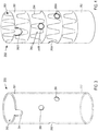
- FIG. 3 illustrates an example of a fenestration template 250 according to an embodiment.
- the fenestration template 250 can be formed, for example, via the process described above and used to generate and/or locate fenestrations on a stent graft. More specifically, in some embodiments, the output device can be a 3-D printer and/or other suitable rapid prototype machine configured to print the fenestration template 250.
- the fenestration template 250 can be formed from any suitable biocompatible material such as those described herein.
- the fenestration template 250 includes a proximal end portion 251 and a distal end portion 252, and defines a lumen 253 and a set of fenestrations 255.
- the shape, diameter, length, etc. of the fenestration template 250 corresponds to the calculated arrangement of the lumen of the aorta segment represented by the updated model.
- the fenestration template 250 corresponds to the updated model defined by the electronic device, which in turn, corresponds to a calculated, projected, and/or modified arrangement of the aorta in response to the insertion and indwelling of, for example, the endovascular stent graft.
- a fenestration template 250 generally has a tubular or cylindrical shape. In some embodiments, such as illustrated in FIG.
- the fenestration template 250 can define the lumen 253 that substantially corresponds to a calculated arrangement of the lumen of the aorta. In some instances, the diameter of the lumen 253 is at least partially based on a diameter of the stent graft to be positioned within the patient.
- the fenestration template 250 is shown and described above as defining the lumen 253 (e.g., is hollow and/or substantially annular), in other embodiments, the fenestration template 250 can be substantially solid and the fenestrations 255 can be, for example, semi-blind, as shown and described in detail in the '998 publication.
- the fenestrations 255 are defined along the fenestration template 250 such that each fenestration 255 corresponds to a calculated position of the corresponding branch vasculature such as, for example, the renal arteries.
- the fenestration template 250 defines and/or can optionally define one or more fenestrations 255 corresponding to one of the SMA, the celiac artery, and/or any other branch vasculature.
- the diameters of the fenestrations 255 defined by the fenestration template can substantially correspond to the actual or calculated diameters of the openings of the branch vessels in fluid communication with a patient's aorta (see e.g., FIGS. 1-2B ).
- the fenestrations 255 can have a predefined diameter, for example, between about 2 mm and about 10 mm. While the fenestration template 250 is shown as having four fenestrations 255, the position and/or number of the fenestrations 255 can be arranged in any suitable manner corresponding to the calculated position and/or number, respectively, of the branch openings defined by the patient's aorta. Thus, the fenestration template 250 can provide a model and/or template used to locate a corresponding set of fenestrations in a stent graft or the like, as described in further detail herein.
- a fenestration template can include a set of markers, indicators, protrusions, spikes, recesses, bumps, and/or any other suitable discontinuity configured to indicate a desired location (e.g., a calculated location) of a fenestration along a stent graft.
- the fenestration template 250 can be formed from multiple materials. For example, one or more portions of the fenestration template 250 that correspond with the fenestrations 255 can be formed from a material substantially different from the remaining portions of the fenestration template 250.
- Such a material can have substantially different mechanical properties than the mechanical properties of a material forming the other portions of the fenestration template 250.
- such materials can form a frangible portion or an otherwise deformable portion corresponding to the fenestrations 255.
- the fenestration template 250 can be used, for example, as a guide to form a set of fenestrations in a stent graft used for endovascular repair of an abdominal aortic aneurysm (see e.g., FIGS. 1-2B ).
- FIG. 4 illustrates at least a portion of a fenestrated stent graft 260 according to an embodiment.
- a stent graft can define one or more fenestrations configured to accommodate one or more branch vessels when the stent graft is deployed in an aorta.
- the fenestrated stent graft 260 includes a proximal end portion 261 and a distal end portion 262, and defines a lumen 263.
- the fenestrated stent graft 260 can be any suitable stent graft and/or prosthetic.
- the fenestrated stent graft 260 can be an off-the-shelf stent graft.
- the fenestrated stent graft 260 can be a patient-specific stent graft with a size, shape, and/or configuration corresponding to the patient's anatomy.
- the fenestrated stent graft 260 can have any suitable shape, size, and/or configuration.
- the stent graft 260 can have a size that is associated with a size of the lumen defined by the aorta.
- the fenestrated stent graft 260 can have a size that is associated with an adjusted or calculated size of the lumen defined by the aorta resulting from the endovascular placement of the fenestrated stent graft 260.
- the fenestrated stent graft 260 can have any suitable mechanical properties such as, for example, strength, stiffness, etc. As shown in FIG.
- the fenestrated stent graft 260 can include a set of stiffening members 264 disposed about the fenestrated stent graft 260, which can, for example, increase a stiffness fenestrated stent graft 260.
- the fenestrated stent graft 260 can be positioned relative to the fenestration template 250 such that the fenestration template 250 can mark, guide, indicate, and/or otherwise provide a template for making a set of fenestrations 265 in the fenestrated stent graft 260.
- the fenestrated stent graft 260 can be inserted into the lumen 253 defined by the fenestration template 250 and positioned in a desired position relative thereto.
- adjustment may be made to the relative positions of the fenestrated stent graft 260 and/or the fenestration template 250 to optimize the fenestration process.
- the fenestrated stent graft 260 and/or fenestration template 250 may be moved along a longitudinal axis and/or rotated relative to each other about the longitudinal axis to avoid placement of fenestrations 255 defined by the fenestration template 250 over the stiffening members 264.
- the fenestrations 265 can be made with the fenestration template 250 still engaged with and/or coupled to the fenestrated stent graft 260.
- the fenestrations 255 defined by the fenestration template 250 can provide a guide or outline along the fenestrated stent graft 260, which in turn, can be cut (e.g., with a blade, a laser, a water jet, etc.), punched, drilled, and/or the like.
- the locations of the fenestrations 265 can be marked, for example, with a sterile pen or other marking devices on the fenestrated stent graft 260 (e.g., through the fenestrations 255 defined by the fenestration template 250) and the actual fenestrations 265 can be defined at the marked locations after the fenestration template 250 is decoupled and/or removed from the fenestrated stent graft 260.
- the fenestrated stent graft 260 can be slid over the fenestration template 250. That is to say, the fenestration template 250 can be inserted into the lumen 263 defined by the fenestrated stent graft 260.
- the fenestrations 255 defined by the fenestration template 250 can be visible through the fenestrated stent graft 260.
- the fenestration template 250 can provide a marking or indicator associated with the locations of the fenestrations 255.
- the fenestrations 265 can be defined along the fenestrated stent graft 260, as described above.
- a coating material can be applied and/or otherwise disposed on a surface of the fenestration template 250 configured to contact the fenestrated stent graft 260, and/or vice versa.
- a coating can, for example, allow for smooth rotation or movement of the fenestrated stent graft 265 relative to the fenestration template 250.
- such coating material can, for example, smooth relatively small-scale roughness due to the layer-by-layer deposition of the modeling material during 3-D printing.
- the fenestrations 265 can be disposed along the fenestrated stent graft 260 in any suitable manner.
- the fenestrations 265 can have any suitable size, diameter, and/or shapes.
- the fenestrations 265 can have substantially the same size and/or shape as the fenestrations 255 defined by the fenestration template 250, which in turn, can correspond to the size and/or shape of the branch vessel openings and/or the adjusted or calculated branch vessel openings in the patient's aorta, as described above.
- the fenestrations 265 can be substantially circular if the corresponding adjusted and/or calculated branch vessel is substantially circular and would otherwise be covered by the graft material when the fenestrated stent graft 260 is positioned in the patient's aorta.
- the fenestrations 265 defined by the fenestrated stent graft 260 can be disposed at any suitable position along a length of the fenestrated stent graft 260.
- the fenestrations 265 can be located at and/or near the proximal end portion 261 or the distal end portion 262 of the fenestrated stent graft 260.
- the fenestrations 265 are disposed at or near the proximal end portion 261 of the fenestrated stent graft 260.
- the peripheral edges of the fenestrated stent graft 260 that define the fenestrations 265 can be at least partially reinforced to provide stability, for example, for anchoring of fenestrated stent graft 260 to the branch vessels extending from the aorta.
- the peripheral edge defining a fenestration 265 can be stitched or sutured using wires and/or can be coupled (e.g., via stitches) to a ring or a similar support frame.
- the size, shape, and/or position of the fenestrations 265 defined by the fenestrated stent graft 260 can correspond to the desired branch vasculature (e.g., the left renal artery 14 and/or the right renal artery 13).
- the renal arteries 13 and/or 14 can also be stented, for example, through the fenestrations 265A (not shown in FIG. 5 ).
- the fenestrated stent graft 260 and the stents within the renal arteries 13 and/or 14 can limit and/or substantially prevent migration of the fenestrated stent graft 260 relative to the patient's aorta 10.
- the fenestrated stent graft 260 can include a second set of fenestrations 265B, which are associated with and/or otherwise correspond to other branch vessels that otherwise, might be blocked by an un-fenestrated portion of the fenestrated stent graft 260.
- the fenestrations 265B can be associated with and/or otherwise correspond to the superior mesenteric artery (SMA) 18 and the celiac artery 19, respectively.
- the fenestrated stent graft 260 can define fenestrations to accommodate more or fewer branch vessels than illustrated here.
- the fenestrated stent graft 260 can define fenestrations to accommodate the inferior mesenteric artery (IMA), internal iliac arteries, and/or the like.
- IMA inferior mesenteric artery
- the fenestrations 265 defined by the fenestrated stent graft 260 can allow blood to flow from the aorta 10 to the branch vasculature, which would otherwise be obstructed by the fenestrated stent graft 260 material.
- the arrangement of the fenestrated stent graft 260 and/or the patient's aorta can be such that a fenestration 265 is partially defined by the fenestrated stent graft 260.
- the proximal most fenestration 265B is disposed at the proximal end of the fenestrated stent graft 260 and corresponds to the celiac artery 19 that is partially covered by the graft material during deployment.
- the fenestrations 265 can be marked to facilitate location of the fenestrations 265 during deployment of the fenestrated stent graft 260.
- the peripheral edges of the fenestrated stent graft 260 that define the fenestrations 265 may be sutured using gold wires and/or wires of other radio-opaque materials.
- the location of the fenestration 265 can be marked by one or more radio-opaque markers 212.
- Such radio-opaque wires or markers can facilitate fluoroscopic visualization of the fenestrations 265 during an endovascular repair procedure and allow a physician to locate the fenestration 265 with respect to the corresponding branch vessel.
- the fenestrations can be sutured and/or otherwise marked using any suitable material that can increase visibility, for example, when using any suitable imaging device (e.g., MRI scan, CAT scan, PET scan, X-Ray scan, ultrasound, etc.).
- the fenestrations 265 each can be accurately sized, shaped, and/or positioned to correspond with its associated branch vasculature, as described in detail above.
- a fenestration template can be, for example, substantially flat and configured to be rearranged to form desired fenestration template.
- FIGS. 6 and 7 illustrate a fenestration template 350 according to another embodiment, in a first configuration and a second configuration, respectively.
- the fenestration template 350 is a substantially flat sheet with fenestrations 355 corresponding to the openings of branch vessels of the aorta (e.g., the aorta 10 in FIG. 1 ).
- the fenestration template 350 can be made of any elastic material such as thermoplastic, plaster, metal alloy, titanium alloy, paper, metal foil, plastic film, photopolymer, a biocompatible graft material, and/or any other suitable material.
- the fenestration template 350 can be manipulated from its first configuration, in which the fenestration template 350 is a substantially flat sheet, to its second configuration, in which the fenestration template 350 at least partially forms a tubular and/or cylindrical shape, as indicated by the arrows AA in FIG. 7 .
- the fenestration template 350 can be manipulated to form a partial tubular or cylindrical structure.
- the fenestration template 350 can be formed from a substantially resilient material that can, for example, maintain its shape until a sufficient force is exerted to reconfigure the fenestration template 350.
- the fenestration member 350 can be positioned relative to a stent graft or the like (e.g., the fenestrated stent graft 160 in FIGS. 4 and 5 ) and reconfigured to be placed in contact with an inner surface or an outer surface of the stent graft.
- the fenestration template 350 can be reconfigured to form a substantially complete tubular or cylindrical structure.
- a first end portion 357 of the fenestration template 350 can be configured to overlap and couple to a second end portion 358 of the fenestration template 350.
- the first end portion 357 and the second end portion 358 can include a coating, an adhesive, and/or the like configured to couple the first end portion 357 to the second end portion 358.
- the first end portion 357 and/or the second end portion 358 can include indicia and/or other indicator configured to indicate, for example, a diameter of the fenestration template 350 when placed in the second configuration.
- the fenestration template 350 can be sized to fit a given stent graft and/or lumen of the aorta.
- the fenestration template 350 defines a set of fenestrations 355 that can be disposed along the fenestration template 350 at a position associated with an opening to a corresponding branch vasculature of the aorta.
- the size, shape, and/or configuration of the fenestrations 355 similarly can be associated with the openings of the branch vasculature.
- the arrangement of the fenestrations 355 can substantially correspond to an adjusted, calculated, updated, and/or otherwise modified arrangement of the patient's aorta in response to the placement of an endovascular stent graft.
- the fenestration template 350 can be transitioned to its second configuration and placed in engagement with an endovascular stent graft to facilitate, mark, locate, and/or otherwise at least partially define a set of fenestrations in the endovascular stent graft that substantially correspond to the modified arrangement of the patient's aorta.
- the stent graft can be positioned within the patient's aorta (see e.g., FIG. 5 ) during any suitable endovascular procedure.
- a fenestration template can include one or more bumps and/or protruding structures instead of or in addition to fenestrations or markings to designate the locations of the fenestrations on the stent graft.
- the protruding structure may be used to mark and/or cut the graft material to define the fenestrations therein.
- such a fenestration template can include one or more protruding structures on the outer surface or on the inner surface of the fenestration template according to what surface is configured to contact the stent graft.
- the protruding structures can be of any suitable dimension and/or shapes.
- the protruding structure can have a semi-spherical shape or a conical shape, and/or can have or form a pointed tip.
- the protruding structures can be configured to mark locations of the fenestrations on the stent graft material upon contact using, for example, a thermal, mechanical, chemical device and/or reaction.
- the protruding structures may be heated (e.g., electrically) to act as thermal cautery tools for generating fenestrations in the graft material.
- the protruding structures may have sharp tips used to puncture the graft material to form the fenestrations therein.
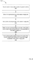
- the method 1000 includes receiving anatomic imaging data of a portion of a patient's anatomy (e.g., including a blood vessel, such as an abdominal aorta, and/or associated branch blood vessels), at 1001.
- an electronic device such as a PC or workstation receives the anatomic imaging data.
- the electronic device can include a graphic user interface-driven application.
- the imaging data is from an imaging device in communication with the host device such as, for example, an X-ray device, a computed tomography (CT) device, computed axial tomography (CAT) device) a magnetic resonance imaging device (MRI), a magnetic resonance angiograph (MRA) device, a positron emission tomography (PET) device, a single photon emission computed tomography (SPECT) device, an ultrasound device, and/or any other suitable device for imaging a portion of a patient and/or a combination thereof (e.g., CT/MRA device, PET/CT device, SPECT/CT device, etc.).
- CT/MRA device computed tomography
- CAT computed axial tomography
- MRA magnetic resonance angiograph
- PET positron emission tomography
- SPECT single photon emission computed tomography
- ultrasound device and/or any other suitable device for imaging a portion of a patient and/or a combination thereof (e.g., CT/MRA
- the anatomic imaging data of the portion of the patient's anatomy can be loaded as an input.
- a user can select and load a DICOM contrast CT series of the patient abdomen.
- a variety of images can be loaded, including, for example, computed tomography (CT) images, magnetic resonance (MR) images, and ultrasound (US) images.
- CT computed tomography
- MR magnetic resonance
- US ultrasound
- two or more images of the same image type or of different image types can be fused to improve image quality, simplify segmentation, and improve measurement accuracy.
- different image types e.g., MR and CT
- some features of the portion of the patient's anatomy may be more clearly visible in one image type than another, so fusion of the information from two or more images can improve the clarity and accuracy of the images and/or data.
- data can be resampled for improved image resolution.
- Data interpolation can be used to improve measurement accuracy. For example, if images are sampled 2 mm apart along the Z-axis, then the point-to-point distance between two images can only be measured in steps of 2 mm. By interpolating between the images (i.e., creating intermediate images between the two), measurement accuracy can be improved.
- an additional CT image can be created from two CT images spaced 2 mm apart, such that the additional CT image is placed between the original two CT images and spaced only 1 mm from each of the first two CT images. Data interpolation can improve the accuracy of measurements to, for example, sub-pixel accuracy.
- a first digital representation of the anatomic imaging data is defined, at 1002.
- the electronic device can define the first digital representation or the like associated with and/or corresponding to the patient's anatomy.
- the first digital representation can be, for example, an anatomic model of the patient's abdominal aorta.
- the first digital representation can be an anatomic model of the patient's abdominal aorta, a first branch blood vessel, and a second branch blood vessel based on the anatomic imaging data.
- a user can manipulate the electronic device to cause the anatomic model to be graphically presented on a screen using, for example, a solid modeling program and/or any other computer-aided design (CAD) program.
- CAD computer-aided design
- the images associated with the anatomic imaging data can be displayed such that the user can better visualize the patient's anatomy.
- the images can be displayed in a standard layout for 3-D medical images.
- the images can be displayed in a 2 x 2 layout as axial, sagittal, and coronal slices.
- the images can also be displayed in a 3-D cube view.
- the user can manipulate the images for improved visualization of the anatomy. For example, the user can step through the slices, change contrast settings, and change the zoom settings (i.e., adjust the magnification).
- Image processing algorithms can be used to segment the portion of the patient's anatomy (e.g., the aorta) to focus on the volume of interest. After segmentation, the image data can be cropped to speed up image processing.
- the volume of interest can be manually entered by a user via a user-selected file or through interactive user input.
- the volume of interest can be determined automatically using image analysis techniques. For example, the aorta can be identified in contrast CT images. Image analysis techniques can then be used to automatically detect a particular portion of the aorta, such as the space ranging from the celiac artery to the renal artery to the ileac arteries.
- Atlas-based methods can be used to model the anatomy to avoid noisy or incomplete data. Such methods begin with the expected layout of the patient's anatomy, such as the relative locations of anatomical features and expected ranges of dimensions. For example, for a typical patient, the celiac artery is expected to be positioned above the renal arties. Additionally, the diameters of the renal arteries are expected to range from about 4 mm to about 10 mm
- the method can include modifying the initial anatomical model (i.e., the first digital representation) created from the anatomic imaging data using additional data collected through any method described herein. Because the initial anatomical model is used as a starting point and the initial anatomical model is then adjusted with collected data, this method avoids holes in the model that can result from incomplete data. Additionally, noise can be avoided because a user or image processing algorithm can recognize if collected data is within an expected range of the initial anatomical model. If collected data is outside of an expected range, the data can be discarded or flagged for review.
- the initial anatomical model i.e., the first digital representation
- a combination of user input and automatic detection is used to define the volume of interest. For example, after an initial automatic detection using the methods described herein, user input can be used to refine the boundaries of the volume of interest.
- the particular portion of the patient's anatomy can be automatically segmented using deformable models.
- the boundary of a vessel can be detected in a first image.
- the boundary can be, for example, circular or elliptical.
- the boundary in the first image can be "grown" through the volume of interest (i.e., the boundary shape in the first image can be stacked through the volume). Constraints can be imposed on the overall shape of the "grown" boundary such as, for example, smoothness or orientation.
- an atlas-based model can be used to segment the vessel.
- An initial "atlas" model can be constructed from training data and expert knowledge. Additional data, which may be collected from the patient, can be used to map the initial "atlas" model to the patient's anatomy.
- portions of the patient's anatomy can be extracted from the segmented images.
- the aortic trunk and the branch vessels can be segmented and extracted.
- Morphological filters can be used to separately extract the aortic trunk and branch vessels.
- elliptical contours can be fitted to the segmented surface points.
- Outlier detection methods can then be used to exclude branch vessel points and only fit points that belong to the main trunk.
- each vessel can be identified using a user's knowledge of anatomy and patient orientation (e.g., right versus left). For example, the user can distinguish between the left and right renal arteries and between the celiac artery and the superior mesenteric artery (SMA). Another example is that the user may know the relative locations of vessels in a typical anatomy (e.g., the celiac is above the renal arteries) and the user can use this information in identifying each vessel. A third example is that the user may intend to identify a portion of the aorta with a specific shape (e.g., a long tube with four to six branch vessels).
- a specific shape e.g., a long tube with four to six branch vessels.
- Each of the dimensions of the specific shape can have an expected range of values (e.g., the aorta diameter will be between 15mm and 30mm).
- knowledge of the anatomy can assist with segmentation and locating, for example, an aneurysm.
- relevant information from the patient's medical record e.g., a missing renal artery can be used.
- centerlines of portions of a patient's anatomy can be extracted from the segmented portions.
- the centerlines of the aortic trunk and branch vessels i.e. the lines passing through the central axes of the aortic trunk and branch vessels and following the geometry of the main trunk and branch vessels
- the centerlines can be extracted automatically.
- a curved planar reformation (CPR) image can be optionally generated and displayed.
- a distance transform can be applied to a segmented image and can connect points with maximum distances using a fast marching method.
- the data can be adjusted and/or updated based on patient data such as a degree of aortic angulation at the juxtarenal neck or other segment of the aorta; a degree, pattern, and location of atherosclerotic disease including plaque, calcification, and/or thrombus; morphometric characteristics of the vascular structure that influence size, position, angulation, or tortuosity such as vessel diameter (i.e., vascular lumen diameter); and/or vessel wall thickness, vessel length, location and number of branch arteries, and/or the like; anthropomorphic data of the patient such as body composition, body temperature, height, weight, BMI, abdominal circumference (absolute or normalized), age, and/or the like; pre-existing vascular or extravascular prostheses or foreign bodies, and/or the like.
- patient data such as a degree of aortic angulation at the juxtarenal neck or other segment of the aorta; a degree, pattern, and location of
- the data can be adjusted and/or updated based on data associated with mechanical properties of the prosthesis such as, for example, body material or fabric type, stent or support strut geometry and/or thickness, type of metals or other support materials, stiffness and diameter of the prosthesis, an amount of oversizing of the prosthesis, and/or the like.
- the data can be adjusted and/or updated based on data associated with a delivery method of the prosthesis such as, for example, an impact of specific delivery methods such as use of guide wires, catheters, and/or the like.
- a second digital representation of the portion of the patient's anatomy is defined based on the modifying of the first digital representation of the anatomic imaging data, at 1004.
- the first digital representation of anatomic imaging data can be modified based on a predetermined data set, and the predetermined data set can be based on data associated with the second digital representation.
- the data associated with the first digital representation can be adjusted and/or updated to define the second digital representation based on an anticipated, predicted, predetermined, calculated, and/or otherwise probable shift in the arrangement resulting from the insertion and indwelling of a prosthetic (e.g., an endovascular stent graft).
- the anatomic imaging data can be a first anatomic imaging data set.
- the modifying of the first digital representation of the first anatomic imaging data set can be based on data associated with the patient-specific prosthetic, a patient, and/or a manner of introducing the patient-specific prosthetic to a portion of a patient's anatomy.
- the data associated with the patient-specific prosthetic, a patient, and/or a manner of introducing the patient-specific prosthetic to a portion of a patient's anatomy can be updated with data associated with a second anatomic imaging data set, the second anatomic imaging data set being representative of the patient-specific prosthetic disposed within the portion of the patient's anatomy.
- the modification of the first digital representation to define a second digital representation of the portion of the patient's anatomy can be based on predicted changes to the centerline of a portion of the patient's anatomy.
- the modification can be based on predicted changes to the extracted centerline of the aortic trunk.
- the extracted centerline (as described above) is typically a sequence of points in 3-D space (e.g., having x-, y-, and z-coordinates).
- the modification of the first digital representation to define a second digital representation of the portion of the patient's anatomy can be based on the expected deformation of the patient's anatomy as a result of inserting a device (e.g., a graft) into the anatomy.
- a device e.g., a graft
- mathematical models of the segmented volumes and/or surfaces such as finite element method (FEM) or parametric representations, can be created based on expected deformation of the segmented volumes and/or surfaces.
- FEM finite element method
- Models reflecting the expected deformation can be built from training data consisting of pre-procedure, intra-procedure, and post-procedure images.
- the anatomy of interest can be segmented and the resulting changes can be modeled using machine learning approaches.
- data can be collected from a deformed portion of one or more patients' anatomy (e.g., a deformed aorta) and the data can be used to create a training data set.
- the training data set can be used to model the predicted deformation of a portion of a patient's anatomy in future procedures.
- the modification of the first digital representation to define a second digital representation of the portion of the patient's anatomy can take into account characteristics of a particular device (e.g., a patient-specific prosthetic) to be delivered to the anatomy.
- a particular device e.g., a patient-specific prosthetic
- the modification can take into account the wire stiffness of a graft and account for variations in wire stiffness between manufacturers.
- a lower order polynomial fit can be used to model the predicted change in centerline if a stiffer device is inserted into the anatomy (e.g. a stiffer graft).
- training data can be used to model changes as a result of the characteristics of particular devices.
- the modification of the first digital representation to define a second digital representation can take into account anatomic-specific information (e.g., characteristics associated with a specific patient or set of patients). For example, if the particular patient's anatomy is unusually angulated, the anatomical shift of the anatomy as a result of a device being inserted (e.g., a graft) is likely to favor one side of the anatomy (e.g. the aorta vessel wall). Additionally, the insertion location (e.g., left versus right femoral artery) can cause the device to favor one side of the anatomy (e.g. aorta vessel wall). Training data can also be used to model changes as a result of a particular patient's anatomy.
- anatomic-specific information e.g., characteristics associated with a specific patient or set of patients. For example, if the particular patient's anatomy is unusually angulated, the anatomical shift of the anatomy as a result of a device being inserted (e.g., a graf
- the user can manually account for patient-specific details (i.e., characteristics associated with a patient). For example, a user can use a different method to locate (for digitally representation) the distal or proximal end of a vessel depending on the presence of a calcium deposit.
- the modification of the first digital representation can take into account patient-specific details using algorithms. For example, the modification can account for calcium deposits or plaque, the presence of artifacts obstructing blood flow through the aorta, and/or the angle of curvature of the aorta and branch vessels.
- intra-procedure images can be used to modify the first representation (i.e. to build a predictive model) based on where the device (e.g. a graft) is expected to eventually be located in the patient based on the side of insertion.
- the device e.g. a graft
- grafts that are inserted from the right side of a patient may typically shift to a positon next to the left side of the aorta wall.
- the expected location can be quantified through intra-operative measurements and a predictive model can be created.
- Calcium deposits along the arterial wall of a vessel can affect the stiffness of the vessel. Additionally, other calcium deposits and/or diseased portions of the vessel can increase or decrease the stiffness of the arterial wall. Stiffness of the vessel wall is inversely related to the amount of flexibility of the vessel wall. In some embodiments, calcium deposits and/or diseased portions can be accounted for during the modification of the first digital representation pre-operatively by modeling the stiffness as a material property. For example, finite element models can be used that model the stiffness as a material property.
- expert clinician knowledge regarding the location of calcium deposits and/or branch vessels can be incorporated into the modification of the first digital representation to define a second digital representation.
- Clinician inputs can be collected and used to modify the first digital representation (i.e., built into a predictive model) that can be applied to future patients and/or procedures. As the number of patients in a training set increases, the accuracy of the predictive model can increase. Additionally, as more data is collected via the training set, outlier patient data can be discarded.
- vessel locations can be predicted by projecting a central point of the vessel along the adjusted centerline of the aorta.
- the identification of the central point of the branch vessels can be performed automatically or manually.
- the centerlines for the branch vessels, the main centerline of the aorta, and the segmented aorta produced by the segmentation steps above can be used to determine the junction point (also referred to as the "branch vessel junction") where a branch vessel centerline and an outer surface or wall of the segmented aorta intersect (i.e. the central point of the vessel along the outer surface of the aorta based on the adjusted centerline of the aorta).
- the vessel radius can then be estimated and the vessel location can be defined as ⁇ the radius from the projected branch vessel junction (i.e. the vessel central point on the outer surface of the segmented aorta).
- centerlines e.g., centerlines of the aortic trunk and branch vessels
- centerlines can be extracted automatically from mathematical models. Said another way, centerlines can be extracted (using methods described herein) from deformed images. In such embodiments, centerlines can be extracted from intra-procedure or post-procedure image data reflecting anatomy deformed by device insertion. Branch vessel locations can then be predicted based on the extracted centerlines. Similarly as described above, these centerlines can be used for pre-procedure planning (e.g. modification of the first digital representation to define a second digital representation) and for training/teaching aids.
- a patient-specific prosthetic template of the portion of the patient's anatomy is formed based, at least in part, on the second digital representation of the anatomic imaging data, at 1005.
- the electronic device can include and/or can send a signal to an output device such as a 3-D printer or a rapid prototyping machine.
- the output device can be caused to output the patient-specific prosthetic template associated with the updated, adjusted, calculated, and/or otherwise modified data, which in turn, is associated with a projected (i.e., predicted), anticipated, and/or calculated arrangement of the patient's abdominal aorta.
- the patient-specific prosthetic template can include openings (fenestrations), protrusions, markers, indicators, frangible portions, and/or any other suitable feature corresponding to, for example, the openings of the aorta leading to the branch vasculature, as described above with reference to, for example, the fenestration template 250 and the fenestrated stent graft 260.
- the patient-specific prosthetic template (also referred to as a "patient-specific fenestration template”) can include a first indicator or marker corresponding to the location of a first branch blood vessel extending from a patient's aorta in the second digital representation and a second indicator or marker corresponding to the location of a second branch blood vessel extending from a patient's aorta in the second digital representation.
- the first marker and the second marker can be a first opening and a second opening in the patient-specific prosthetic template.
- the relative locations of the vessels can be automatically quantified in a 3-D or 4-D coordinate system. Additionally, relevant dimensions such as, for example, diameters and volume of flow, can be automatically quantified.
- This information can be used to modify the first digital representation to define the second digital representation of the portion of the patient's anatomy.
- the second digital representation can then be used to create a fenestration template (also referred to as a "patient-specific prosthetic template").
- the fenestration template can be used to modify a graft.
- the fenestration template can be used to create fenestrations in a graft at the predicted location of the vessels such that fenestrations are at the appropriate location and of an appropriate size and shape to allow pass-through of the vessels.
- the fenestration template can be a flat sheet configured to be wrapped around a portion of an aortic graft to allow a user to identify fenestration locations in the aortic graft.
- a first fenestration location in the aortic graft can correspond to the first marker and a second fenestration location in the aortic graft can correspond to the second marker.
- the fenestration template can include a tubular body defining a lumen configured to be at least partially disposed over and aortic graft.
- the fenestration template can include a tubular body configured to be at least partially disposed in a lumen of an aortic graft.
- the digital representation data can directly feed into the graft manufacturing process to produce a fenestrated graft.
- the average diameter of the aorta at user-specified end points at the celiac and SMA branch vessels can be computed.
- the locations of the branch vessels can be translated to cylindrical coordinates on the surface of a cylinder.
- the cylinder can have a diameter equal to the average diameter of the aorta (e.g., the average of the diameter at the celiac and the SMA branch vessels).
- Each branch vessel location can be defined by its central point and radius on the surface of this cylinder as described above.
- a template representation (a patient-specific prosthetic template) of the vessels can be created.
- the template representation can be used, for example, with a 3-D printer or fed into a graft manufacturing process such as, for example, an STL model or other CAD models.
- the template representation can be an STL model of a cylindrical shell having a wall thickness of 2 mm with fenestrations (i.e., holes) corresponding to the branch vessels.
- an internal serial number can be placed at the bottom of the STL model.
- Graft manufacturer data such as CAD models and strut patterns, can be incorporated into the template representation.
- manufacturer strut pattern information can be used to define fenestrations in locations on a graft without struts.
- the graft manufacturing process can be modified such that the strut patterns are customized to not overlap with fenestration locations.
- the patient-specific prosthetic template can be used to form the patient-specific prosthetic.
- the patient-specific prosthetic can be, for example, a stent graft.
- the stent graft and the patient-specific template can be placed in contact and/or otherwise made to engage each other.
- the patient-specific template can be used to form at least a portion of the stent graft (i.e., the patient-specific prosthetic).
- the patient-specific template can define a set of fenestrations (i.e., lumens) in a wall of the patient-specific template associated with the openings of the branch vessels of the aorta.
- the patient-specific template can be used to guide the placement of and/or otherwise locate a corresponding set of fenestrations in the stent graft, each of which corresponds to an opening of a different branch vessel.
- the patient-specific template can direct a means of defining the fenestrations (e.g., a blade, a laser, a water jet, a punch, a drill, and/or the like).
- the patient-specific template can be configured to at least partially form the fenestrations of the stent graft (e.g., the patient-specific template can include a protrusion or the like configured to puncture and/or otherwise define an opening in the stent graft.
- the patient-specific template can facilitate the formation of the fenestrations defined by the stent graft, which are each disposed along the stent graft in a position corresponding to a modified and/or shifted position of a branch vessel of the aorta, which results from the placement of the stent graft, as described in detail above with reference to the fenestration patient-specific template 250 and the fenestrated stent graft 260.
- Some of the embodiments described herein are configured to define a first digital representation of anatomic imaging data of a portion of a patient's anatomy and to modify the first digital representation to define a second digital representation of the portion of the patient's anatomy based on a set of characteristics associated with the patient, a prosthetic, and/or a manner of delivering the prosthetic.
- the second digital representation of the portion of the patient's anatomy can be from a plurality of digital representations of the portion of patient's anatomy. That is to say, in some embodiments, the modifying of the first digital representation of the portion of the patient's anatomy can result in a plurality of modified digital representations of the portion of the patient's anatomy (including the second digital representation).
- each modified digital representation of the portion of the patient's anatomy can be based on a different set of characteristics or a different combination of the characteristics associated with the patient, the prosthetic, and/or the manner of delivering the prosthetic.
- a first digital representation of a portion of a patient's anatomy can be modified to define a second digital representation of the portion of the patient's anatomy based on patient data, prosthetic data, and/or a first method of delivering the prosthetic.
- the first digital representation of the portion of the patient's anatomy can be modified to define a third digital representation of the portion of the patient's anatomy based on the patient data, the prosthetic data, and/or a second method of delivering the prosthetic.
- a patient-specific prosthetic template such as the fenestration templates 150, 250, and/or 350 based on the second digital representation can also be specific to the first method of delivering the prosthetic, while a patient-specific prosthetic template based on the third digital representation can also be specific to the second method of delivering the prosthetic.
- a digital representation can also be based on the size, shape, and/or configuration of the prosthetic. As such, a user can input a selection or the like of a digital representation of a specific prosthetic template from a plurality of specific prosthetic templates.
- a score, confidence value, rating, and/or any other indicator can be associated with the digital representation of each prosthetic template and can be indicative of an accuracy of the digital representation of each prosthetic template and the associated modified representation of the patient's anatomy.
- a digital representation of a plurality of patient-specific prosthetic templates and a plurality of confidence values can be defined. Each confidence value from the plurality of confidence values can be associated with the digital representation of a different patient-specific prosthetic template from the plurality of patient-specific prosthetic templates and can represent a degree of accuracy between the digital representation of that patient-specific prosthetic template and the second digital representation of the anatomic imaging data.
- a user can select a digital representation of the prosthetic template with the highest score suitable for a patient.
- any of the embodiments described herein can be configured to define a modified representation of a portion of a patient's anatomy based on data associated with any suitable set of characteristics associated with the patient, a prosthetic, a manner of delivery, and/or the like.
- the data associated with the set of characteristics can be updated based on, for example, empirical data and/or the like.
- a value, weight, score, factor, and/or the like can be associated with each characteristic in the set of characteristics.
- anatomic imaging data can be taken of the portion of the patient's anatomy after the delivery of a prosthetic and based on data included in the post-delivery anatomic imaging data the value, weight, score, factor, and/or the like associated with the set of characteristics can be updated.
- the accuracy of a projected change in the portion of the anatomy as a result of the delivery and/or indwelling of a prosthetic can be increased based on adjusting and/or "tuning" the weight and/or influence of one or more characteristics associated with the patient, the prosthetic, and/or the delivery method.
- Some embodiments described herein relate to a computer storage product with a non-transitory computer-readable medium (also can be referred to as a non-transitory processor-readable medium) having instructions or computer code thereon for performing various computer-implemented operations.
- the computer-readable medium or processor-readable medium
- the media and computer code may be those designed and constructed for the specific purpose or purposes.
- non-transitory computer-readable media include, but are not limited to, magnetic storage media such as hard disks, floppy disks, and magnetic tape; optical storage media such as Compact Disc/Digital Video Discs (CD/DVDs), Compact Disc-Read Only Memories (CD-ROMs), and holographic devices; magneto-optical storage media such as optical disks; carrier wave signal processing modules; and hardware devices that are specially configured to store and execute program code, such as Application-Specific Integrated Circuits (ASICs), Programmable Logic Devices (PLDs), Read-Only Memory (ROM) and Random-Access Memory (RAM) devices.
- ASICs Application-Specific Integrated Circuits
- PLDs Programmable Logic Devices
- ROM Read-Only Memory
- RAM Random-Access Memory
- Other embodiments described herein relate to a computer program product, which can include, for example, the instructions and/or computer code discussed herein.
- Hardware modules may include, for example, a general-purpose processor, a field programmable gate array (FPGA), and/or an application specific integrated circuit (ASIC).
- Software modules (executed on hardware) can be expressed in a variety of software languages (e.g., computer code), including C, C++, JavaTM, Ruby, Visual BasicTM, and/or other object-oriented, procedural, or other programming language and development tools.
- Examples of computer code include, but are not limited to, micro-code or micro-instructions, machine instructions, such as produced by a compiler, code used to produce a web service, and files containing higher-level instructions that are executed by a computer using an interpreter.
- embodiments may be implemented using imperative programming languages (e.g., C, FORTRAN, etc.), functional programming languages (Haskell, Erlang, etc.), logical programming languages (e.g., Prolog), object-oriented programming languages (e.g., Java, C++, etc.) or other suitable programming languages and/or development tools.
- Additional examples of computer code include, but are not limited to, control signals, encrypted code, and compressed code.
- Some embodiments and/or methods described herein can be performed by software (executed on hardware), hardware, or a combination thereof and configured to process and/or execute one or more programs and/or instructions stored, for example, in memory.
- some of the embodiments described such as the host device 120 can be configured to process and/or execute one or more programs associated with 3-D solid modeling, computer aided design (CAD), volume or surface reconstruction, image analysis and/or segmentation, and/or the like.
- Such programs can include but are not limited to, for example, MATLAB, TeraRecon, FreeCAD, SolidWorks, AutoCAD, Creo, and/or the like.
- Such programs can be used, for example, to identify features of interest, which can be traced with spline curves fit to user-specified points.
- indicators or markers can be placed at specific 3-D locations to indicate the origins of the branch vessels.
- the outlines are converted to 3-D contours that define the feature locations in the 3-D space.
- the 3-D contours can be converted to a mesh to define a 3-D surface model.
- segmentation software can be configured to obtain different types of imaging data such as CT imaging data, ultrasound data, and/or the like.
- the size of the generated 3-D surface model can be modified to optimize the graft fenestration process. For example, the surface model may be radially expanded to add a predefined wall thickness to allow generation of a solid fenestration template.
- such programs can produce 3-D and multi-planar views of CT image sets.
- a visualization tool can perform automatic vessel boundary detection, which can be imported into segmentation software that generates the 3-D surfaces to expedite the model generation and hence the fenestration generation process.
- such visualization tools can automatically generate 3-D surface data for a digital model and/or a fenestration template. Once the vessel boundaries are identified, corresponding openings in the 3-D digital model can be created and/or defined. In some embodiments, a subtraction between the solid part model and a cylinder with the desired fenestration diameter can define the openings in the 3-D digital model.
- holes representing the origins of branch vessels may be added using a CAD program such as those listed above.
- a 3-D digital model is converted to a solid object model format such as stereolithography (STL) or Virtual Reality Modeling Language (VRML) that is supported by a 3-D printer or similar template generation device.
- STL stereolithography
- VRML Virtual Reality Modeling Language
- the availability of automatic aorta boundary detection makes the creation of the present fenestration template a practical option for routine use in endovascular aortic aneurysm repair.
- Raw imaging data or the segmented aorta boundaries and fenestration locations may be sent to an outside processing facility, and the fenestration template shipped back to the surgery site. Therefore, individual clinical sites not employ individuals with expertise in image segmentation, CAD software, and/or 3-D output devices.
Landscapes
- Health & Medical Sciences (AREA)
- Engineering & Computer Science (AREA)
- Life Sciences & Earth Sciences (AREA)
- General Health & Medical Sciences (AREA)
- Biomedical Technology (AREA)
- Veterinary Medicine (AREA)
- Heart & Thoracic Surgery (AREA)
- Animal Behavior & Ethology (AREA)
- Public Health (AREA)
- Surgery (AREA)
- Physics & Mathematics (AREA)
- Medical Informatics (AREA)
- Nuclear Medicine, Radiotherapy & Molecular Imaging (AREA)
- Gastroenterology & Hepatology (AREA)
- Pulmonology (AREA)
- Cardiology (AREA)
- Oral & Maxillofacial Surgery (AREA)
- Transplantation (AREA)
- Vascular Medicine (AREA)
- General Physics & Mathematics (AREA)
- Theoretical Computer Science (AREA)
- Robotics (AREA)
- Molecular Biology (AREA)
- Computer Vision & Pattern Recognition (AREA)
- Quality & Reliability (AREA)
- Radiology & Medical Imaging (AREA)
- Geometry (AREA)
- Prostheses (AREA)
Priority Applications (1)
| Application Number | Priority Date | Filing Date | Title |
|---|---|---|---|
| EP21186509.2A EP3932366B1 (en) | 2015-04-23 | 2016-04-25 | Devices for anatomic mapping for prosthetic implants |
Applications Claiming Priority (2)
| Application Number | Priority Date | Filing Date | Title |
|---|---|---|---|
| US201562151506P | 2015-04-23 | 2015-04-23 | |
| PCT/US2016/029185 WO2016172694A1 (en) | 2015-04-23 | 2016-04-25 | Devices and methods for anatomic mapping for prosthetic implants |
Related Child Applications (1)
| Application Number | Title | Priority Date | Filing Date |
|---|---|---|---|
| EP21186509.2A Division EP3932366B1 (en) | 2015-04-23 | 2016-04-25 | Devices for anatomic mapping for prosthetic implants |
Publications (2)
| Publication Number | Publication Date |
|---|---|
| EP3285686A1 EP3285686A1 (en) | 2018-02-28 |
| EP3285686B1 true EP3285686B1 (en) | 2021-07-28 |
Family
ID=56015088
Family Applications (2)
| Application Number | Title | Priority Date | Filing Date |
|---|---|---|---|
| EP21186509.2A Active EP3932366B1 (en) | 2015-04-23 | 2016-04-25 | Devices for anatomic mapping for prosthetic implants |
| EP16723572.0A Active EP3285686B1 (en) | 2015-04-23 | 2016-04-25 | Methods for anatomic mapping for prosthetic implants |
Family Applications Before (1)
| Application Number | Title | Priority Date | Filing Date |
|---|---|---|---|
| EP21186509.2A Active EP3932366B1 (en) | 2015-04-23 | 2016-04-25 | Devices for anatomic mapping for prosthetic implants |
Country Status (8)
| Country | Link |
|---|---|
| US (4) | US9629686B2 (ja) |
| EP (2) | EP3932366B1 (ja) |
| JP (2) | JP6995740B2 (ja) |
| CN (1) | CN107979991B (ja) |
| AU (1) | AU2016253034A1 (ja) |
| CA (1) | CA2983464A1 (ja) |
| ES (1) | ES2886029T3 (ja) |
| WO (1) | WO2016172694A1 (ja) |
Families Citing this family (25)
| Publication number | Priority date | Publication date | Assignee | Title |
|---|---|---|---|---|
| CN107979991B (zh) | 2015-04-23 | 2020-06-12 | 主动脉公司 | 对假体植入物进行解剖映射的设备和方法 |
| JP6979010B2 (ja) | 2015-07-08 | 2021-12-08 | アオーティカ コーポレイション | 補綴インプラントのための解剖学的マッピングのための装置および方法 |
| ES2860458T3 (es) | 2016-06-13 | 2021-10-05 | Aortica Corp | Sistemas y dispositivos para marcar y/o reforzar fenestraciones en implantes protésicos |
| CN113229998A (zh) | 2016-08-02 | 2021-08-10 | 主动脉公司 | 用于将假体植入物联接到开窗体的系统、装置和方法 |
| US11166764B2 (en) | 2017-07-27 | 2021-11-09 | Carlsmed, Inc. | Systems and methods for assisting and augmenting surgical procedures |
| EP3687445A2 (en) | 2017-09-25 | 2020-08-05 | Aortica Corporation | Systems, devices, and methods for coupling a prosthetic implant to a fenestrated body |
| US11382735B2 (en) | 2017-11-27 | 2022-07-12 | SB-Kawasumi Laboratories, Inc. | Stent graft and stent graft indwelling device |
| CN109984861A (zh) * | 2017-12-29 | 2019-07-09 | 杭州唯强医疗科技有限公司 | 可用于腹主动脉疾病介入治疗的覆膜支架 |
| US11432943B2 (en) | 2018-03-14 | 2022-09-06 | Carlsmed, Inc. | Systems and methods for orthopedic implant fixation |
| US11439514B2 (en) | 2018-04-16 | 2022-09-13 | Carlsmed, Inc. | Systems and methods for orthopedic implant fixation |
| US11284989B2 (en) * | 2018-04-24 | 2022-03-29 | Medtronic Vascular, Inc. | Stent-graft prosthesis with pressure relief channels |
| CN108652787B (zh) * | 2018-05-06 | 2020-05-22 | 王潇 | 用于腹主动脉瘤修复的覆膜支架及其使用方法 |
| DE102018005070A1 (de) | 2018-06-26 | 2020-01-02 | Rheinisch-Westfälische Technische Hochschule (Rwth) Aachen | Stentgraft und Verfahren zu dessen Herstellung |
| USD958151S1 (en) | 2018-07-30 | 2022-07-19 | Carlsmed, Inc. | Display screen with a graphical user interface for surgical planning |
| WO2020056186A1 (en) | 2018-09-12 | 2020-03-19 | Carlsmed, Inc. | Systems and methods for orthopedic implants |
| US20220265353A1 (en) * | 2019-07-11 | 2022-08-25 | The Cleveland Clinic Foundation | System and method for model-based stent design and placement |
| EP3771449A1 (de) * | 2019-07-31 | 2021-02-03 | Siemens Healthcare GmbH | Verfahren zur verformungssimulation und vorrichtung |
| US10902944B1 (en) | 2020-01-06 | 2021-01-26 | Carlsmed, Inc. | Patient-specific medical procedures and devices, and associated systems and methods |
| US11376076B2 (en) | 2020-01-06 | 2022-07-05 | Carlsmed, Inc. | Patient-specific medical systems, devices, and methods |
| IT202100000128A1 (it) * | 2021-01-07 | 2022-07-07 | Luca Rubino | Metodo per la realizzazione di stent graft aortici personalizzati ed associato dispositivo di posizionamento |
| KR102575514B1 (ko) * | 2021-06-23 | 2023-09-06 | 재단법인 아산사회복지재단 | 이관 스텐트 및 이관 스텐트의 제작방법 |
| USD1016289S1 (en) * | 2022-01-18 | 2024-02-27 | Sutherland Cardiovascular Ltd. | Aortic root replacement graft |
| US11443838B1 (en) | 2022-02-23 | 2022-09-13 | Carlsmed, Inc. | Non-fungible token systems and methods for storing and accessing healthcare data |
| US11806241B1 (en) | 2022-09-22 | 2023-11-07 | Carlsmed, Inc. | System for manufacturing and pre-operative inspecting of patient-specific implants |
| US11793577B1 (en) | 2023-01-27 | 2023-10-24 | Carlsmed, Inc. | Techniques to map three-dimensional human anatomy data to two-dimensional human anatomy data |
Citations (5)
| Publication number | Priority date | Publication date | Assignee | Title |
|---|---|---|---|---|
| US5370692A (en) * | 1992-08-14 | 1994-12-06 | Guild Associates, Inc. | Rapid, customized bone prosthesis |
| WO2007045000A2 (en) * | 2005-10-14 | 2007-04-19 | Vantus Technology Corporation | Personal fit medical implants and orthopedic surgical instruments and methods for making |
| US20070293936A1 (en) * | 2006-04-28 | 2007-12-20 | Dobak John D Iii | Systems and methods for creating customized endovascular stents and stent grafts |
| WO2013066880A1 (en) * | 2011-11-01 | 2013-05-10 | Thapliyal Hira V | Personalized prosthesis and methods of use |
| WO2015141798A1 (ja) * | 2014-03-20 | 2015-09-24 | 重之 尾崎 | 弁尖形成用テンプレート |
Family Cites Families (33)
| Publication number | Priority date | Publication date | Assignee | Title |
|---|---|---|---|---|
| JP4405002B2 (ja) * | 1999-09-10 | 2010-01-27 | 阿部 慎一 | ステントグラフト設計装置 |
| US7840393B1 (en) | 2000-10-04 | 2010-11-23 | Trivascular, Inc. | Virtual prototyping and testing for medical device development |
| FR2817460B1 (fr) | 2000-12-04 | 2003-09-05 | Ge Med Sys Global Tech Co Llc | Procede et systeme pour simuler l'elargissement de diametre d'une lesion d'un vaisseau sanguin, en particulier une stenose, a l'aide d'une prothese endovasculaire |
| WO2002061688A2 (en) * | 2001-01-29 | 2002-08-08 | The Acrobot Company Limited | Modelling for surgery |
| US6551341B2 (en) | 2001-06-14 | 2003-04-22 | Advanced Cardiovascular Systems, Inc. | Devices configured from strain hardened Ni Ti tubing |
| AU2002316254A1 (en) | 2001-06-18 | 2003-01-02 | Eva Corporation | Prosthetic graft assembly and method of use |
| US7937660B2 (en) | 2002-04-19 | 2011-05-03 | Medtronic Vascular, Inc. | Computer-based methods and structures for stent-graft selection |
| US8246673B2 (en) * | 2002-09-19 | 2012-08-21 | Exstent Limited | External support for a blood vessel |
| AU2004270239C1 (en) | 2003-09-04 | 2011-07-07 | Cook Biotech Incorporated | Extracellular matrix composite materials, and manufacture and use thereof |
| WO2005034808A1 (en) | 2003-10-10 | 2005-04-21 | William A. Cook Australia Pty. Ltd. | Fenestrated stent grafts |
| US7197170B2 (en) | 2003-11-10 | 2007-03-27 | M2S, Inc. | Anatomical visualization and measurement system |
| DE102004044435A1 (de) * | 2004-09-14 | 2006-03-30 | Siemens Ag | Verfahren und Vorrichtung zur Diagnose und Therapie des Aortenaneurysmas |
| US8478437B2 (en) | 2006-06-16 | 2013-07-02 | The Invention Science Fund I, Llc | Methods and systems for making a blood vessel sleeve |
| US20080139915A1 (en) | 2006-12-07 | 2008-06-12 | Medtronic Vascular, Inc. | Vascular Position Locating and/or Mapping Apparatus and Methods |
| US20080255582A1 (en) | 2007-04-11 | 2008-10-16 | Harris John F | Methods and Template Assembly for Implanting an Electrode Array in a Patient |
| WO2009025783A1 (en) * | 2007-08-17 | 2009-02-26 | Mohamed Rashwan Mahfouz | Implant design analysis suite |
| JP5140857B2 (ja) * | 2008-05-12 | 2013-02-13 | 株式会社大野興業 | 手術シミュレーション用軟質血管モデルの製造方法 |
| US7970719B2 (en) * | 2008-06-06 | 2011-06-28 | Siemens Aktiengesellschaft | Method and simulation device for structurally individualized simulation of the introduction of a wall support element into a section of a tubular structure |
| JP5882743B2 (ja) * | 2009-02-25 | 2016-03-09 | ジンマー,インコーポレイティド | カスタマイズされた整形外科用インプラント及び関連する方法並びにインテリジェント軟骨システム |
| US8682626B2 (en) * | 2010-07-21 | 2014-03-25 | Siemens Aktiengesellschaft | Method and system for comprehensive patient-specific modeling of the heart |
| US8315812B2 (en) | 2010-08-12 | 2012-11-20 | Heartflow, Inc. | Method and system for patient-specific modeling of blood flow |
| US20130237804A1 (en) * | 2011-08-30 | 2013-09-12 | Qi Imaging, Llc | Time varying density of tissues |
| US9095421B2 (en) | 2012-04-18 | 2015-08-04 | Medtronic Vascular, Inc. | Multi-leaflet coupling for branch vessel connection |
| US9811613B2 (en) * | 2012-05-01 | 2017-11-07 | University Of Washington Through Its Center For Commercialization | Fenestration template for endovascular repair of aortic aneurysms |
| WO2014053616A1 (en) * | 2012-10-05 | 2014-04-10 | Materialise N.V. | Customized aortic stent device and method of making the same |
| US8897513B2 (en) * | 2012-12-28 | 2014-11-25 | Siemens Aktiengesellschaft | Method of selecting a stent based on stress of a blood vessel |
| CN104240220A (zh) * | 2013-06-17 | 2014-12-24 | 北京三星通信技术研究有限公司 | 用于基于图像分割血管的设备和方法 |
| EP3061015A2 (en) * | 2013-10-24 | 2016-08-31 | Cathworks Ltd. | Vascular characteristic determination with correspondence modeling of a vascular tree |
| US9986938B2 (en) | 2014-02-25 | 2018-06-05 | Medis Associated B.V. | Method and device for determining a geometrical parameter of a blood vessel |
| US8958623B1 (en) * | 2014-04-29 | 2015-02-17 | Heartflow, Inc. | Systems and methods for correction of artificial deformation in anatomic modeling |
| JP2015217170A (ja) * | 2014-05-19 | 2015-12-07 | 株式会社東芝 | X線診断装置 |
| CN107979991B (zh) | 2015-04-23 | 2020-06-12 | 主动脉公司 | 对假体植入物进行解剖映射的设备和方法 |
| JP6979010B2 (ja) | 2015-07-08 | 2021-12-08 | アオーティカ コーポレイション | 補綴インプラントのための解剖学的マッピングのための装置および方法 |
-
2016
- 2016-04-25 CN CN201680030896.5A patent/CN107979991B/zh active Active
- 2016-04-25 JP JP2018506814A patent/JP6995740B2/ja active Active
- 2016-04-25 AU AU2016253034A patent/AU2016253034A1/en not_active Abandoned
- 2016-04-25 WO PCT/US2016/029185 patent/WO2016172694A1/en active Application Filing
- 2016-04-25 EP EP21186509.2A patent/EP3932366B1/en active Active
- 2016-04-25 EP EP16723572.0A patent/EP3285686B1/en active Active
- 2016-04-25 CA CA2983464A patent/CA2983464A1/en not_active Abandoned
- 2016-04-25 ES ES16723572T patent/ES2886029T3/es active Active
- 2016-05-24 US US15/163,255 patent/US9629686B2/en active Active
-
2017
- 2017-03-17 US US15/461,922 patent/US10653484B2/en active Active
-
2020
- 2020-04-30 US US16/863,316 patent/US11160613B2/en active Active
-
2021
- 2021-09-27 US US17/486,572 patent/US11786357B2/en active Active
- 2021-12-15 JP JP2021203474A patent/JP2022031938A/ja active Pending
Patent Citations (5)
| Publication number | Priority date | Publication date | Assignee | Title |
|---|---|---|---|---|
| US5370692A (en) * | 1992-08-14 | 1994-12-06 | Guild Associates, Inc. | Rapid, customized bone prosthesis |
| WO2007045000A2 (en) * | 2005-10-14 | 2007-04-19 | Vantus Technology Corporation | Personal fit medical implants and orthopedic surgical instruments and methods for making |
| US20070293936A1 (en) * | 2006-04-28 | 2007-12-20 | Dobak John D Iii | Systems and methods for creating customized endovascular stents and stent grafts |
| WO2013066880A1 (en) * | 2011-11-01 | 2013-05-10 | Thapliyal Hira V | Personalized prosthesis and methods of use |
| WO2015141798A1 (ja) * | 2014-03-20 | 2015-09-24 | 重之 尾崎 | 弁尖形成用テンプレート |
Also Published As
| Publication number | Publication date |
|---|---|
| EP3932366B1 (en) | 2024-05-01 |
| US20200100840A9 (en) | 2020-04-02 |
| US20170333133A1 (en) | 2017-11-23 |
| JP6995740B2 (ja) | 2022-01-17 |
| AU2016253034A1 (en) | 2017-11-02 |
| EP3932366A2 (en) | 2022-01-05 |
| JP2018520816A (ja) | 2018-08-02 |
| EP3285686A1 (en) | 2018-02-28 |
| CA2983464A1 (en) | 2016-10-27 |
| US9629686B2 (en) | 2017-04-25 |
| US11786357B2 (en) | 2023-10-17 |
| CN107979991A (zh) | 2018-05-01 |
| ES2886029T3 (es) | 2021-12-16 |
| US10653484B2 (en) | 2020-05-19 |
| US20160310216A1 (en) | 2016-10-27 |
| JP2022031938A (ja) | 2022-02-22 |
| US20220008134A1 (en) | 2022-01-13 |
| US11160613B2 (en) | 2021-11-02 |
| US20200390499A1 (en) | 2020-12-17 |
| CN107979991B (zh) | 2020-06-12 |
| WO2016172694A1 (en) | 2016-10-27 |
| EP3932366A3 (en) | 2022-01-19 |
Similar Documents
| Publication | Publication Date | Title |
|---|---|---|
| US11786357B2 (en) | Devices and methods for anatomic mapping for prosthetic implants | |
| US11615531B2 (en) | Devices and methods for anatomic mapping for prosthetic implants | |
| US20210187856A1 (en) | Fenestration template for endovascular repair of aortic aneurysms | |
| EP3025638B1 (en) | Method for determining the final length of stents before the positioning thereof |
Legal Events
| Date | Code | Title | Description |
|---|---|---|---|
| STAA | Information on the status of an ep patent application or granted ep patent |
Free format text: STATUS: THE INTERNATIONAL PUBLICATION HAS BEEN MADE |
|
| PUAI | Public reference made under article 153(3) epc to a published international application that has entered the european phase |
Free format text: ORIGINAL CODE: 0009012 |
|
| STAA | Information on the status of an ep patent application or granted ep patent |
Free format text: STATUS: REQUEST FOR EXAMINATION WAS MADE |
|
| 17P | Request for examination filed |
Effective date: 20171011 |
|
| AK | Designated contracting states |
Kind code of ref document: A1 Designated state(s): AL AT BE BG CH CY CZ DE DK EE ES FI FR GB GR HR HU IE IS IT LI LT LU LV MC MK MT NL NO PL PT RO RS SE SI SK SM TR |
|
| AX | Request for extension of the european patent |
Extension state: BA ME |
|
| RIN1 | Information on inventor provided before grant (corrected) |
Inventor name: VAN BIBBER, RICHARD Inventor name: DUMPURI, PRASHANTH Inventor name: DOUTHITT, THOMAS C. Inventor name: TIRUMALAI, ARUN PALLIGARANAI |
|
| RIN1 | Information on inventor provided before grant (corrected) |
Inventor name: TIRUMALAI, ARUN PALLIGARANAI Inventor name: DUMPURI, PRASHANTH Inventor name: VAN BIBBER, RICHARD Inventor name: DOUTHITT, THOMAS C. |
|
| DAV | Request for validation of the european patent (deleted) | ||
| DAX | Request for extension of the european patent (deleted) | ||
| STAA | Information on the status of an ep patent application or granted ep patent |
Free format text: STATUS: EXAMINATION IS IN PROGRESS |
|
| 17Q | First examination report despatched |
Effective date: 20191010 |
|
| STAA | Information on the status of an ep patent application or granted ep patent |
Free format text: STATUS: EXAMINATION IS IN PROGRESS |
|
| GRAP | Despatch of communication of intention to grant a patent |
Free format text: ORIGINAL CODE: EPIDOSNIGR1 |
|
| STAA | Information on the status of an ep patent application or granted ep patent |
Free format text: STATUS: GRANT OF PATENT IS INTENDED |
|
| RIC1 | Information provided on ipc code assigned before grant |
Ipc: A61F 2/07 20130101AFI20200724BHEP |
|
| INTG | Intention to grant announced |
Effective date: 20200820 |
|
| GRAJ | Information related to disapproval of communication of intention to grant by the applicant or resumption of examination proceedings by the epo deleted |
Free format text: ORIGINAL CODE: EPIDOSDIGR1 |
|
| STAA | Information on the status of an ep patent application or granted ep patent |
Free format text: STATUS: EXAMINATION IS IN PROGRESS |
|
| INTC | Intention to grant announced (deleted) | ||
| GRAP | Despatch of communication of intention to grant a patent |
Free format text: ORIGINAL CODE: EPIDOSNIGR1 |
|
| STAA | Information on the status of an ep patent application or granted ep patent |
Free format text: STATUS: GRANT OF PATENT IS INTENDED |
|
| INTG | Intention to grant announced |
Effective date: 20210210 |
|
| RAP3 | Party data changed (applicant data changed or rights of an application transferred) |
Owner name: AORTICA CORPORATION |
|
| GRAS | Grant fee paid |
Free format text: ORIGINAL CODE: EPIDOSNIGR3 |
|
| GRAA | (expected) grant |
Free format text: ORIGINAL CODE: 0009210 |
|
| STAA | Information on the status of an ep patent application or granted ep patent |
Free format text: STATUS: THE PATENT HAS BEEN GRANTED |
|
| AK | Designated contracting states |
Kind code of ref document: B1 Designated state(s): AL AT BE BG CH CY CZ DE DK EE ES FI FR GB GR HR HU IE IS IT LI LT LU LV MC MK MT NL NO PL PT RO RS SE SI SK SM TR |
|
| REG | Reference to a national code |
Ref country code: GB Ref legal event code: FG4D |
|
| REG | Reference to a national code |
Ref country code: CH Ref legal event code: EP |
|
| REG | Reference to a national code |
Ref country code: DE Ref legal event code: R096 Ref document number: 602016061230 Country of ref document: DE |
|
| REG | Reference to a national code |
Ref country code: AT Ref legal event code: REF Ref document number: 1414020 Country of ref document: AT Kind code of ref document: T Effective date: 20210815 |
|
| REG | Reference to a national code |
Ref country code: IE Ref legal event code: FG4D |
|
| REG | Reference to a national code |
Ref country code: LT Ref legal event code: MG9D |
|
| REG | Reference to a national code |
Ref country code: NL Ref legal event code: MP Effective date: 20210728 |
|
| REG | Reference to a national code |
Ref country code: AT Ref legal event code: MK05 Ref document number: 1414020 Country of ref document: AT Kind code of ref document: T Effective date: 20210728 |
|
| REG | Reference to a national code |
Ref country code: ES Ref legal event code: FG2A Ref document number: 2886029 Country of ref document: ES Kind code of ref document: T3 Effective date: 20211216 |
|
| PG25 | Lapsed in a contracting state [announced via postgrant information from national office to epo] |
Ref country code: RS Free format text: LAPSE BECAUSE OF FAILURE TO SUBMIT A TRANSLATION OF THE DESCRIPTION OR TO PAY THE FEE WITHIN THE PRESCRIBED TIME-LIMIT Effective date: 20210728 Ref country code: SE Free format text: LAPSE BECAUSE OF FAILURE TO SUBMIT A TRANSLATION OF THE DESCRIPTION OR TO PAY THE FEE WITHIN THE PRESCRIBED TIME-LIMIT Effective date: 20210728 Ref country code: AT Free format text: LAPSE BECAUSE OF FAILURE TO SUBMIT A TRANSLATION OF THE DESCRIPTION OR TO PAY THE FEE WITHIN THE PRESCRIBED TIME-LIMIT Effective date: 20210728 Ref country code: BG Free format text: LAPSE BECAUSE OF FAILURE TO SUBMIT A TRANSLATION OF THE DESCRIPTION OR TO PAY THE FEE WITHIN THE PRESCRIBED TIME-LIMIT Effective date: 20211028 Ref country code: LT Free format text: LAPSE BECAUSE OF FAILURE TO SUBMIT A TRANSLATION OF THE DESCRIPTION OR TO PAY THE FEE WITHIN THE PRESCRIBED TIME-LIMIT Effective date: 20210728 Ref country code: PT Free format text: LAPSE BECAUSE OF FAILURE TO SUBMIT A TRANSLATION OF THE DESCRIPTION OR TO PAY THE FEE WITHIN THE PRESCRIBED TIME-LIMIT Effective date: 20211129 Ref country code: NL Free format text: LAPSE BECAUSE OF FAILURE TO SUBMIT A TRANSLATION OF THE DESCRIPTION OR TO PAY THE FEE WITHIN THE PRESCRIBED TIME-LIMIT Effective date: 20210728 Ref country code: NO Free format text: LAPSE BECAUSE OF FAILURE TO SUBMIT A TRANSLATION OF THE DESCRIPTION OR TO PAY THE FEE WITHIN THE PRESCRIBED TIME-LIMIT Effective date: 20211028 Ref country code: FI Free format text: LAPSE BECAUSE OF FAILURE TO SUBMIT A TRANSLATION OF THE DESCRIPTION OR TO PAY THE FEE WITHIN THE PRESCRIBED TIME-LIMIT Effective date: 20210728 Ref country code: HR Free format text: LAPSE BECAUSE OF FAILURE TO SUBMIT A TRANSLATION OF THE DESCRIPTION OR TO PAY THE FEE WITHIN THE PRESCRIBED TIME-LIMIT Effective date: 20210728 |
|
| PG25 | Lapsed in a contracting state [announced via postgrant information from national office to epo] |
Ref country code: PL Free format text: LAPSE BECAUSE OF FAILURE TO SUBMIT A TRANSLATION OF THE DESCRIPTION OR TO PAY THE FEE WITHIN THE PRESCRIBED TIME-LIMIT Effective date: 20210728 Ref country code: LV Free format text: LAPSE BECAUSE OF FAILURE TO SUBMIT A TRANSLATION OF THE DESCRIPTION OR TO PAY THE FEE WITHIN THE PRESCRIBED TIME-LIMIT Effective date: 20210728 Ref country code: GR Free format text: LAPSE BECAUSE OF FAILURE TO SUBMIT A TRANSLATION OF THE DESCRIPTION OR TO PAY THE FEE WITHIN THE PRESCRIBED TIME-LIMIT Effective date: 20211029 |
|
| PG25 | Lapsed in a contracting state [announced via postgrant information from national office to epo] |
Ref country code: DK Free format text: LAPSE BECAUSE OF FAILURE TO SUBMIT A TRANSLATION OF THE DESCRIPTION OR TO PAY THE FEE WITHIN THE PRESCRIBED TIME-LIMIT Effective date: 20210728 |
|
| REG | Reference to a national code |
Ref country code: DE Ref legal event code: R097 Ref document number: 602016061230 Country of ref document: DE |
|
| REG | Reference to a national code |
Ref country code: DE Ref legal event code: R081 Ref document number: 602016061230 Country of ref document: DE Owner name: BOLTON MEDICAL, INC., SUNRISE, US Free format text: FORMER OWNER: AORTICA CORPORATION, SUNRISE, FL, US |
|
| PG25 | Lapsed in a contracting state [announced via postgrant information from national office to epo] |
Ref country code: SM Free format text: LAPSE BECAUSE OF FAILURE TO SUBMIT A TRANSLATION OF THE DESCRIPTION OR TO PAY THE FEE WITHIN THE PRESCRIBED TIME-LIMIT Effective date: 20210728 Ref country code: SK Free format text: LAPSE BECAUSE OF FAILURE TO SUBMIT A TRANSLATION OF THE DESCRIPTION OR TO PAY THE FEE WITHIN THE PRESCRIBED TIME-LIMIT Effective date: 20210728 Ref country code: RO Free format text: LAPSE BECAUSE OF FAILURE TO SUBMIT A TRANSLATION OF THE DESCRIPTION OR TO PAY THE FEE WITHIN THE PRESCRIBED TIME-LIMIT Effective date: 20210728 Ref country code: EE Free format text: LAPSE BECAUSE OF FAILURE TO SUBMIT A TRANSLATION OF THE DESCRIPTION OR TO PAY THE FEE WITHIN THE PRESCRIBED TIME-LIMIT Effective date: 20210728 Ref country code: CZ Free format text: LAPSE BECAUSE OF FAILURE TO SUBMIT A TRANSLATION OF THE DESCRIPTION OR TO PAY THE FEE WITHIN THE PRESCRIBED TIME-LIMIT Effective date: 20210728 Ref country code: AL Free format text: LAPSE BECAUSE OF FAILURE TO SUBMIT A TRANSLATION OF THE DESCRIPTION OR TO PAY THE FEE WITHIN THE PRESCRIBED TIME-LIMIT Effective date: 20210728 |
|
| PLBE | No opposition filed within time limit |
Free format text: ORIGINAL CODE: 0009261 |
|
| STAA | Information on the status of an ep patent application or granted ep patent |
Free format text: STATUS: NO OPPOSITION FILED WITHIN TIME LIMIT |
|
| REG | Reference to a national code |
Ref country code: GB Ref legal event code: 732E Free format text: REGISTERED BETWEEN 20220526 AND 20220601 |
|
| 26N | No opposition filed |
Effective date: 20220429 |
|
| REG | Reference to a national code |
Ref country code: ES Ref legal event code: PC2A Owner name: BOLTON MEDICAL, INC. Effective date: 20220714 |
|
| REG | Reference to a national code |
Ref country code: CH Ref legal event code: PL |
|
| REG | Reference to a national code |
Ref country code: BE Ref legal event code: MM Effective date: 20220430 |
|
| PG25 | Lapsed in a contracting state [announced via postgrant information from national office to epo] |
Ref country code: MC Free format text: LAPSE BECAUSE OF FAILURE TO SUBMIT A TRANSLATION OF THE DESCRIPTION OR TO PAY THE FEE WITHIN THE PRESCRIBED TIME-LIMIT Effective date: 20210728 Ref country code: LU Free format text: LAPSE BECAUSE OF NON-PAYMENT OF DUE FEES Effective date: 20220425 Ref country code: LI Free format text: LAPSE BECAUSE OF NON-PAYMENT OF DUE FEES Effective date: 20220430 Ref country code: CH Free format text: LAPSE BECAUSE OF NON-PAYMENT OF DUE FEES Effective date: 20220430 |
|
| PG25 | Lapsed in a contracting state [announced via postgrant information from national office to epo] |
Ref country code: BE Free format text: LAPSE BECAUSE OF NON-PAYMENT OF DUE FEES Effective date: 20220430 |
|
| PGFP | Annual fee paid to national office [announced via postgrant information from national office to epo] |
Ref country code: FR Payment date: 20230309 Year of fee payment: 8 |
|
| PGFP | Annual fee paid to national office [announced via postgrant information from national office to epo] |
Ref country code: IT Payment date: 20230310 Year of fee payment: 8 |
|
| P01 | Opt-out of the competence of the unified patent court (upc) registered |
Effective date: 20230526 |
|
| PGFP | Annual fee paid to national office [announced via postgrant information from national office to epo] |
Ref country code: ES Payment date: 20230512 Year of fee payment: 8 Ref country code: DE Payment date: 20230228 Year of fee payment: 8 |
|
| PG25 | Lapsed in a contracting state [announced via postgrant information from national office to epo] |
Ref country code: HU Free format text: LAPSE BECAUSE OF FAILURE TO SUBMIT A TRANSLATION OF THE DESCRIPTION OR TO PAY THE FEE WITHIN THE PRESCRIBED TIME-LIMIT; INVALID AB INITIO Effective date: 20160425 |
|
| PGFP | Annual fee paid to national office [announced via postgrant information from national office to epo] |
Ref country code: IE Payment date: 20240223 Year of fee payment: 9 |
|
| PG25 | Lapsed in a contracting state [announced via postgrant information from national office to epo] |
Ref country code: MK Free format text: LAPSE BECAUSE OF FAILURE TO SUBMIT A TRANSLATION OF THE DESCRIPTION OR TO PAY THE FEE WITHIN THE PRESCRIBED TIME-LIMIT Effective date: 20210728 Ref country code: CY Free format text: LAPSE BECAUSE OF FAILURE TO SUBMIT A TRANSLATION OF THE DESCRIPTION OR TO PAY THE FEE WITHIN THE PRESCRIBED TIME-LIMIT Effective date: 20210728 |
|
| PGFP | Annual fee paid to national office [announced via postgrant information from national office to epo] |
Ref country code: GB Payment date: 20240307 Year of fee payment: 9 |