EP3025638B1 - Method for determining the final length of stents before the positioning thereof - Google Patents
Method for determining the final length of stents before the positioning thereof Download PDFInfo
- Publication number
- EP3025638B1 EP3025638B1 EP14859121.7A EP14859121A EP3025638B1 EP 3025638 B1 EP3025638 B1 EP 3025638B1 EP 14859121 A EP14859121 A EP 14859121A EP 3025638 B1 EP3025638 B1 EP 3025638B1
- Authority
- EP
- European Patent Office
- Prior art keywords
- stent
- length
- vascular structure
- radius
- change
- Prior art date
- Legal status (The legal status is an assumption and is not a legal conclusion. Google has not performed a legal analysis and makes no representation as to the accuracy of the status listed.)
- Active
Links
- 238000000034 method Methods 0.000 title claims description 57
- 230000002792 vascular Effects 0.000 claims description 68
- 230000008859 change Effects 0.000 claims description 60
- 230000006870 function Effects 0.000 description 15
- 238000009954 braiding Methods 0.000 description 9
- 206010002329 Aneurysm Diseases 0.000 description 8
- 201000008450 Intracranial aneurysm Diseases 0.000 description 8
- 210000004204 blood vessel Anatomy 0.000 description 7
- 230000000877 morphologic effect Effects 0.000 description 7
- 238000001125 extrusion Methods 0.000 description 4
- 238000004458 analytical method Methods 0.000 description 3
- 230000017531 blood circulation Effects 0.000 description 3
- 230000000694 effects Effects 0.000 description 3
- 238000011156 evaluation Methods 0.000 description 3
- 238000010191 image analysis Methods 0.000 description 3
- 230000011218 segmentation Effects 0.000 description 3
- 230000006978 adaptation Effects 0.000 description 2
- 210000001367 artery Anatomy 0.000 description 2
- 238000004590 computer program Methods 0.000 description 2
- 238000002059 diagnostic imaging Methods 0.000 description 2
- 230000000004 hemodynamic effect Effects 0.000 description 2
- 238000002513 implantation Methods 0.000 description 2
- 238000007917 intracranial administration Methods 0.000 description 2
- 230000003902 lesion Effects 0.000 description 2
- 238000004088 simulation Methods 0.000 description 2
- 241001465754 Metazoa Species 0.000 description 1
- 208000031481 Pathologic Constriction Diseases 0.000 description 1
- 208000027418 Wounds and injury Diseases 0.000 description 1
- 230000003044 adaptive effect Effects 0.000 description 1
- 230000002411 adverse Effects 0.000 description 1
- 210000003484 anatomy Anatomy 0.000 description 1
- 238000002399 angioplasty Methods 0.000 description 1
- 210000002565 arteriole Anatomy 0.000 description 1
- 230000008901 benefit Effects 0.000 description 1
- 210000000013 bile duct Anatomy 0.000 description 1
- 210000004004 carotid artery internal Anatomy 0.000 description 1
- 238000010276 construction Methods 0.000 description 1
- 210000004351 coronary vessel Anatomy 0.000 description 1
- 230000006378 damage Effects 0.000 description 1
- 230000007547 defect Effects 0.000 description 1
- 230000010339 dilation Effects 0.000 description 1
- 239000003814 drug Substances 0.000 description 1
- 238000002474 experimental method Methods 0.000 description 1
- 238000000605 extraction Methods 0.000 description 1
- 230000004907 flux Effects 0.000 description 1
- 210000003090 iliac artery Anatomy 0.000 description 1
- 238000003709 image segmentation Methods 0.000 description 1
- 239000007943 implant Substances 0.000 description 1
- 238000000338 in vitro Methods 0.000 description 1
- 208000014674 injury Diseases 0.000 description 1
- 238000003780 insertion Methods 0.000 description 1
- 230000037431 insertion Effects 0.000 description 1
- 210000000936 intestine Anatomy 0.000 description 1
- 238000011835 investigation Methods 0.000 description 1
- 239000003550 marker Substances 0.000 description 1
- 238000013178 mathematical model Methods 0.000 description 1
- 238000005259 measurement Methods 0.000 description 1
- 239000007769 metal material Substances 0.000 description 1
- 238000013508 migration Methods 0.000 description 1
- 230000005012 migration Effects 0.000 description 1
- 230000003278 mimic effect Effects 0.000 description 1
- HLXZNVUGXRDIFK-UHFFFAOYSA-N nickel titanium Chemical compound [Ti].[Ti].[Ti].[Ti].[Ti].[Ti].[Ti].[Ti].[Ti].[Ti].[Ti].[Ni].[Ni].[Ni].[Ni].[Ni].[Ni].[Ni].[Ni].[Ni].[Ni].[Ni].[Ni].[Ni].[Ni] HLXZNVUGXRDIFK-UHFFFAOYSA-N 0.000 description 1
- 229910001000 nickel titanium Inorganic materials 0.000 description 1
- 238000012014 optical coherence tomography Methods 0.000 description 1
- 210000000664 rectum Anatomy 0.000 description 1
- 208000037803 restenosis Diseases 0.000 description 1
- 230000036262 stenosis Effects 0.000 description 1
- 208000037804 stenosis Diseases 0.000 description 1
- 238000012360 testing method Methods 0.000 description 1
- 238000012285 ultrasound imaging Methods 0.000 description 1
- 210000001635 urinary tract Anatomy 0.000 description 1
- 238000010200 validation analysis Methods 0.000 description 1
- 210000003462 vein Anatomy 0.000 description 1
Images


Classifications
-
- A—HUMAN NECESSITIES
- A61—MEDICAL OR VETERINARY SCIENCE; HYGIENE
- A61B—DIAGNOSIS; SURGERY; IDENTIFICATION
- A61B6/00—Apparatus for radiation diagnosis, e.g. combined with radiation therapy equipment
- A61B6/12—Devices for detecting or locating foreign bodies
-
- G—PHYSICS
- G06—COMPUTING; CALCULATING OR COUNTING
- G06T—IMAGE DATA PROCESSING OR GENERATION, IN GENERAL
- G06T7/00—Image analysis
- G06T7/0002—Inspection of images, e.g. flaw detection
- G06T7/0012—Biomedical image inspection
-
- A—HUMAN NECESSITIES
- A61—MEDICAL OR VETERINARY SCIENCE; HYGIENE
- A61B—DIAGNOSIS; SURGERY; IDENTIFICATION
- A61B5/00—Measuring for diagnostic purposes; Identification of persons
-
- A—HUMAN NECESSITIES
- A61—MEDICAL OR VETERINARY SCIENCE; HYGIENE
- A61B—DIAGNOSIS; SURGERY; IDENTIFICATION
- A61B34/00—Computer-aided surgery; Manipulators or robots specially adapted for use in surgery
- A61B34/10—Computer-aided planning, simulation or modelling of surgical operations
-
- A—HUMAN NECESSITIES
- A61—MEDICAL OR VETERINARY SCIENCE; HYGIENE
- A61B—DIAGNOSIS; SURGERY; IDENTIFICATION
- A61B8/00—Diagnosis using ultrasonic, sonic or infrasonic waves
- A61B8/08—Detecting organic movements or changes, e.g. tumours, cysts, swellings
- A61B8/0833—Detecting organic movements or changes, e.g. tumours, cysts, swellings involving detecting or locating foreign bodies or organic structures
- A61B8/0841—Detecting organic movements or changes, e.g. tumours, cysts, swellings involving detecting or locating foreign bodies or organic structures for locating instruments
-
- A—HUMAN NECESSITIES
- A61—MEDICAL OR VETERINARY SCIENCE; HYGIENE
- A61F—FILTERS IMPLANTABLE INTO BLOOD VESSELS; PROSTHESES; DEVICES PROVIDING PATENCY TO, OR PREVENTING COLLAPSING OF, TUBULAR STRUCTURES OF THE BODY, e.g. STENTS; ORTHOPAEDIC, NURSING OR CONTRACEPTIVE DEVICES; FOMENTATION; TREATMENT OR PROTECTION OF EYES OR EARS; BANDAGES, DRESSINGS OR ABSORBENT PADS; FIRST-AID KITS
- A61F2/00—Filters implantable into blood vessels; Prostheses, i.e. artificial substitutes or replacements for parts of the body; Appliances for connecting them with the body; Devices providing patency to, or preventing collapsing of, tubular structures of the body, e.g. stents
- A61F2/82—Devices providing patency to, or preventing collapsing of, tubular structures of the body, e.g. stents
-
- G—PHYSICS
- G01—MEASURING; TESTING
- G01N—INVESTIGATING OR ANALYSING MATERIALS BY DETERMINING THEIR CHEMICAL OR PHYSICAL PROPERTIES
- G01N15/00—Investigating characteristics of particles; Investigating permeability, pore-volume, or surface-area of porous materials
- G01N15/08—Investigating permeability, pore-volume, or surface area of porous materials
- G01N15/088—Investigating volume, surface area, size or distribution of pores; Porosimetry
-
- G—PHYSICS
- G06—COMPUTING; CALCULATING OR COUNTING
- G06T—IMAGE DATA PROCESSING OR GENERATION, IN GENERAL
- G06T7/00—Image analysis
- G06T7/60—Analysis of geometric attributes
-
- G—PHYSICS
- G16—INFORMATION AND COMMUNICATION TECHNOLOGY [ICT] SPECIALLY ADAPTED FOR SPECIFIC APPLICATION FIELDS
- G16H—HEALTHCARE INFORMATICS, i.e. INFORMATION AND COMMUNICATION TECHNOLOGY [ICT] SPECIALLY ADAPTED FOR THE HANDLING OR PROCESSING OF MEDICAL OR HEALTHCARE DATA
- G16H50/00—ICT specially adapted for medical diagnosis, medical simulation or medical data mining; ICT specially adapted for detecting, monitoring or modelling epidemics or pandemics
- G16H50/50—ICT specially adapted for medical diagnosis, medical simulation or medical data mining; ICT specially adapted for detecting, monitoring or modelling epidemics or pandemics for simulation or modelling of medical disorders
-
- G—PHYSICS
- G16—INFORMATION AND COMMUNICATION TECHNOLOGY [ICT] SPECIALLY ADAPTED FOR SPECIFIC APPLICATION FIELDS
- G16Z—INFORMATION AND COMMUNICATION TECHNOLOGY [ICT] SPECIALLY ADAPTED FOR SPECIFIC APPLICATION FIELDS, NOT OTHERWISE PROVIDED FOR
- G16Z99/00—Subject matter not provided for in other main groups of this subclass
-
- A—HUMAN NECESSITIES
- A61—MEDICAL OR VETERINARY SCIENCE; HYGIENE
- A61B—DIAGNOSIS; SURGERY; IDENTIFICATION
- A61B34/00—Computer-aided surgery; Manipulators or robots specially adapted for use in surgery
- A61B34/10—Computer-aided planning, simulation or modelling of surgical operations
- A61B2034/101—Computer-aided simulation of surgical operations
- A61B2034/102—Modelling of surgical devices, implants or prosthesis
-
- A—HUMAN NECESSITIES
- A61—MEDICAL OR VETERINARY SCIENCE; HYGIENE
- A61B—DIAGNOSIS; SURGERY; IDENTIFICATION
- A61B34/00—Computer-aided surgery; Manipulators or robots specially adapted for use in surgery
- A61B34/10—Computer-aided planning, simulation or modelling of surgical operations
- A61B2034/108—Computer aided selection or customisation of medical implants or cutting guides
-
- A—HUMAN NECESSITIES
- A61—MEDICAL OR VETERINARY SCIENCE; HYGIENE
- A61B—DIAGNOSIS; SURGERY; IDENTIFICATION
- A61B5/00—Measuring for diagnostic purposes; Identification of persons
- A61B5/20—Measuring for diagnostic purposes; Identification of persons for measuring urological functions restricted to the evaluation of the urinary system
-
- A—HUMAN NECESSITIES
- A61—MEDICAL OR VETERINARY SCIENCE; HYGIENE
- A61B—DIAGNOSIS; SURGERY; IDENTIFICATION
- A61B5/00—Measuring for diagnostic purposes; Identification of persons
- A61B5/68—Arrangements of detecting, measuring or recording means, e.g. sensors, in relation to patient
- A61B5/6846—Arrangements of detecting, measuring or recording means, e.g. sensors, in relation to patient specially adapted to be brought in contact with an internal body part, i.e. invasive
- A61B5/6847—Arrangements of detecting, measuring or recording means, e.g. sensors, in relation to patient specially adapted to be brought in contact with an internal body part, i.e. invasive mounted on an invasive device
- A61B5/6862—Stents
-
- A—HUMAN NECESSITIES
- A61—MEDICAL OR VETERINARY SCIENCE; HYGIENE
- A61F—FILTERS IMPLANTABLE INTO BLOOD VESSELS; PROSTHESES; DEVICES PROVIDING PATENCY TO, OR PREVENTING COLLAPSING OF, TUBULAR STRUCTURES OF THE BODY, e.g. STENTS; ORTHOPAEDIC, NURSING OR CONTRACEPTIVE DEVICES; FOMENTATION; TREATMENT OR PROTECTION OF EYES OR EARS; BANDAGES, DRESSINGS OR ABSORBENT PADS; FIRST-AID KITS
- A61F2/00—Filters implantable into blood vessels; Prostheses, i.e. artificial substitutes or replacements for parts of the body; Appliances for connecting them with the body; Devices providing patency to, or preventing collapsing of, tubular structures of the body, e.g. stents
- A61F2/82—Devices providing patency to, or preventing collapsing of, tubular structures of the body, e.g. stents
- A61F2/86—Stents in a form characterised by the wire-like elements; Stents in the form characterised by a net-like or mesh-like structure
-
- A—HUMAN NECESSITIES
- A61—MEDICAL OR VETERINARY SCIENCE; HYGIENE
- A61F—FILTERS IMPLANTABLE INTO BLOOD VESSELS; PROSTHESES; DEVICES PROVIDING PATENCY TO, OR PREVENTING COLLAPSING OF, TUBULAR STRUCTURES OF THE BODY, e.g. STENTS; ORTHOPAEDIC, NURSING OR CONTRACEPTIVE DEVICES; FOMENTATION; TREATMENT OR PROTECTION OF EYES OR EARS; BANDAGES, DRESSINGS OR ABSORBENT PADS; FIRST-AID KITS
- A61F2240/00—Manufacturing or designing of prostheses classified in groups A61F2/00 - A61F2/26 or A61F2/82 or A61F9/00 or A61F11/00 or subgroups thereof
- A61F2240/001—Designing or manufacturing processes
- A61F2240/002—Designing or making customized prostheses
-
- G—PHYSICS
- G06—COMPUTING; CALCULATING OR COUNTING
- G06F—ELECTRIC DIGITAL DATA PROCESSING
- G06F30/00—Computer-aided design [CAD]
-
- G—PHYSICS
- G06—COMPUTING; CALCULATING OR COUNTING
- G06T—IMAGE DATA PROCESSING OR GENERATION, IN GENERAL
- G06T2200/00—Indexing scheme for image data processing or generation, in general
- G06T2200/04—Indexing scheme for image data processing or generation, in general involving 3D image data
Definitions
- the present invention refers to a new method for determining the change in length of a stent which will occur after it has been implanted inside a vascular structure. Said determination is carried out on the basis of the relationship of said change in length with the morphological characteristics of the vascular structure of interest.
- the term stent is a medical Anglicism in common use to designate a cannula or device of a cylindrical or tubular shape for intraluminal, usually intravascular, use, which is placed inside an anatomical structure or bodily duct in order to keep it permeable or prevent its collapse after dilation, clearing or surgical release.
- a stent is typically implanted in a blood vessel at the site of a stenosis or intraluminal aneurysm, i.e. using so-called “minimally invasive techniques", in which the stent is contained in a radially compressed configuration by a sheath or catheter and is delivered using a stent application device or "inserter" into the required site.
- the inserter may enter the body from a place of access outside the body, such as through the patient's skin or using a technique of incision in which the blood vessel of entry is exposed to minor surgical equipment.
- stent also refers to grafts, stent-grafts, vena cava filters, expandable structures and similar implantable medical devices, which are radially expandable endoprostheses. Usually they are intravascular implants capable of being implanted transluminally and they are enlarged radially after being inserted percutaneously.
- Stents can be implanted in various lumina or vessels in the body, such as in the vascular system, the urinary tract, and bile ducts, among others. Said stents can be used to reinforce blood vessels and prevent restenosis following angioplasty in the vascular system. Stents may be self-expanding, such as nitinol shape memory stents; also they may be mechanically expandable, such as a balloon-expandable stent; or they may be hybrid expandable.
- intraluminal stents The use of intraluminal stents is very common in various areas of medicine and veterinary practice. There are various designs of stents for intraluminal insertion into blood vessels and other lumina to prevent or reverse their occlusion. In general, three basic categories of stent-type devices are considered to exist, as follows:
- the present invention refers to self-expanding stent-type devices which, optionally, have the ability to expand by heat, which are inserted into a vessel within the body in a radially compressed form and mechanically change to a radially expanded form. Once the stent is placed in the desired position in the blood vessel, it expands radially, exerting outwards pressure on the internal surface of the wall of the body vessel in which it has been positioned.
- Braided stents are manufactured by braiding (interweaving) wires of a thin metallic material according to different braiding patterns.
- United States Patent US6083257A describes a method for braiding stents. According to the number of wires, the braiding angle, the nominal radius, the nominal length, and the braiding pattern used, the mechanical properties and density of the resulting stent mesh may vary considerably.
- the present invention covers both braided and unbraided stents.
- the term "nominal radius” refers to the radius adopted by the stent when it is left freely outside a vessel or the positioning device and it coincides with the maximum radius when it is released outside the vessel.
- the term "nominal length” refers to the length adopted by the stent when it is left freely outside a vessel or the positioning device. Therefore, the stent adopts the "nominal length” when it possesses its “nominal radius”.
- Stents are often used for the treatment of intracranial aneurysms (IA), a sector in which there are various types of braided stents.
- IA intracranial aneurysms
- One of these types is known as a "Flow Diverter” (FD, its initials in English), it is densely braided and is placed longitudinally along the vessel affected by the aneurysm, and covers the neck of the aneurysm.
- coarse braided stents are also used as a scaffolding for the protection of the neck of the IA after the positioning of an intravascular coil, as is made known in United States Patent US6010468A .
- Stents are positioned in the desired place using a catheter, in image-guided operations, typically with an interventional X-ray image, with the aid of a contrast marker which shows the location of the vessel lumen and, where appropriate, the aneurysm to be treated.
- the catheter is inserted into the body normally through arteries, for example the iliac artery, and is guided to the location of the aneurysm by a neurointerventional radiologist. Said radiologist will select the position at which the distal end of the stent is placed and will gradually unsheathe the stent until it is fully released in the vessel being treated.
- stents present the difficulty that the final length of the stent when it is positioned inside the body is not accurately known in advance and is difficult to predict with the naked eye.
- a stent When a stent is released outside the human body, as mentioned previously, it adopts its nominal radius. However, if this stent is placed inside a vessel with a radius smaller than its nominal radius, the vessel walls prevent the full expansion of the stent and this forces the device to present a configuration with greater length.
- the fact that the change in the total length of the stent depends on the morphology of the vessel makes it very difficult to predict the final length of said device, prior to its positioning. As the medical practitioner is unable to predict accurately the final length of the stent placed inside the patient, it may happen that collateral branches of the vessel being treated become obstructed or occluded, and this may cause injury to the patient.
- International Patent Application WO2006/093776 discloses a procedure for modelling stents based on the use of an ultrasound imaging system for obtaining images of blood vessels, detecting defects in said vessels and using said images to perform graphic simulations with various stents to check whether the length and position are appropriate.
- International Patent Application WO2011/038044 discloses an automated procedure for simulating the length and position of stents based on the obtainment of images of the lumen of the blood vessel by means of optical coherence tomography. From the images obtained, a three-dimensional reconstruction is made of the contours of the vessel lumen, data are obtained relating to the diameter of the vessel and the blood flow rate, pressure and resistance in order finally to simulate and optimise the length and/or position of the stent.
- Patent Application DE102012217268 A1 discloses a method for supporting planning of stent implantation in coronary vessel, for aneurysm treatment.
- the method involves receiving a three-dimensional data set comprising a vessel portion of a target area of an investigation object. A diameter course is determined along the vessel portion. A stent position is received within the vessel portion.
- a planning value is determined by entering the stent position, a predetermined dependence of a stent length by a stent diameter and the diameter course along the vessel portion, and is visualized.
- United States Patent Application US2007/0135707 discloses the obtainment of three-dimensional images with which a model of the vessel to be treated can be constructed in order to detect the lesion and its characteristics and simulate the stent to be used and the position at which it will be placed.
- the present inventors have developed a method for determining, before its positioning, the final length a stent will have after it is placed in a vascular structure. Said method makes it possible to determine, prior to its implantation and with a high degree of accuracy, the final length of a stent on the basis of the initial position in which it is placed in said vascular structure.
- the computer-implemented method of this invention is based on an analysis of the local morphology of the vascular structure in which said stent will be placed and an analysis of the change in length of this, and it requires the definition and use of a ratio indicating the change in length of the stent as a function of the local morphology of the vessel and the place where it is intended to place the device.
- the method for determining the final length of a stent before it is positioned in a vascular structure consists of the following steps:
- the method of the present invention may be applied to any type of braided or unbraided stent, provided that the length of said stent changes when its diameter varies.
- the determination of the indicator ratio of the change in length of the stent as a function of the local morphology of the vascular structure of step a) of the method of the present invention is specific to each type of stent to be used.
- different morphological descriptors of vascular structures are used such as the average radius (average distance from the centreline to the points on the cross section of the vascular structure at that point of the centreline), maximum inscribed sphere radius (MISR, initials in English, minimum distance from the centreline to the surface of the vascular structure), cross sectional area (cross sectional area at a point on the centreline), perimeter of the cross section (length of the curve obtained by cutting a cross section of the vascular structure), minimum radius of the cross section, maximum radius of the cross section, and curvature/torsion, among others.
- MISR maximum inscribed sphere radius
- MISR initials in English, minimum distance from the centreline to the surface of the vascular structure
- cross sectional area cross sectional area at a point on the centreline
- the vascular structure in which the stent will be positioned must be provided in the form of a three-dimensional surface.
- Said three-dimensional surface of the vascular structure may be obtained by any method known in the art, for example, by image segmentation of an angiographic image ( Hernández, M. and Frangi, A.F. "Non-parametric geodesic active regions: method and evaluation for cerebral aneurysms segmentation in 3DRA and CTA" Medical Image Analysis, 2007, 11(3), 224-241 ; and Antigua, L. et al.
- the three-dimensional surface of the vascular structure can be represented by means of a polygonal mesh, in which the resolution can be adjusted in order to obtain relevant information on the morphology of the vascular structure.
- these techniques are known in the art, and any other known technique may be used provided that it allows a three-dimensional surface of the vascular structure in which the stent will be positioned to be obtained.
- the method of the present invention it is not only possible to predict, before its positioning, the final length of a stent when it is positioned inside a vessel, but it is also possible to detect regions in which there could be poor apposition of the stent to the walls of the vascular structure, occlusion or total or partial covering of ramified vessels and the porosity or density resulting from the stent.
- the use of the method of the present invention makes it possible for a neurointerventional radiologist, for example, to plan the treatment and ascertain the final disposition of the stent before the said treatment is carried out and therefore this will enable him to select the optimal stent and the exact location at which said stent will be positioned.
- step d) may be carried out continuously instead of performing the discretisation of the centreline of the vascular structure.
- the method for determining the final length of a stent of the present invention comprises the following steps:
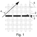
- Figure 1 shows an interweave pattern of a braided stent known in the art, in which a wire -1- is highlighted and it is shown how said wire -1- crosses in front -2- and behind -3- other wires.
- Figure 1 also shows the braiding angle -5- and the direction of braiding -4-.
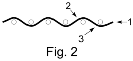
- Figure 2 shows a front view of the interweave pattern shown in figure 1 . It is also observed how the marked wire -1- crosses over -2- and under -3- other wires which form said stent.
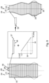
- Figure 3 shows a graph which represents an example of a linear ratio between the change in length of the stent and the radius of the tube or vessel. Furthermore, the following are indicated in the graph: the nominal length -6- of the stent, the nominal radius -7- of the stent, the constrained radius -8- of the stent, the constrained length -9- of the stent and the interpolation of an intermediate radius -y- to obtain the change in length -x-
- Figure 4 shows the helicoidal distribution of the wires of a braided stent, including the path of a wire marked -10-, the length of the device -11-, the braiding angle -12-, the number of wires -13- and the radius -14-.
- Figure 5 shows a braided stent in the expanded and unconstrained state and both the nominal length -6- and the nominal radius -7- are indicated.
- Figure 6 shows a braided stent in the constrained state and the constrained radius -8- and the constrained length -9- may be observed.
- the cross section of a vessel is observed, in which the following may be distinguished: the centreline of the vessel -26-, the minimum radius of the cross section of the vessel -29-, the maximum radius of the cross section of the vessel -30-, the cross sectional area of the vessel -31-, the perimeter of the cross section of the vessel -32- and the maximum inscribed sphere radius of the vessel -33- (the minimum distance from the centreline to the surface of the vascular structure).
- Figures 7 b) and c) show different stents positioned in the same initial position of the same vessel and detail the fact of using a short -15- or long -16-device in a vessel-type structure -24-, the presence of ramified vessels -17-, the nominal lengths -18- and -20-, the final lengths -19- and -21-, the centreline of the vessel -26- and the initial position for positioning the stent -27-.
- Figure 8 shows the superimposition of the braided stent on the vessel and, after performing the interpolation, the adaptation of the stent to the morphology of the vessel -24-.
- a braided stent in the unconstrained state -22- and a braided stent in the constrained state -23- appear.
- vascular structure refers to arteries, arterioles, veins, the intestine, rectum and any other structure of a tubular type present in the human or animal body which is susceptible of treatment with stents.
- the terms “stent”, “stent-type device” refer to braided, unbraided and equivalent stents. Furthermore, the method of the present invention covers both constant radius (cylindrical) stents and non-constant radius stents (conical, combinations of conical/ cylindrical, among others).
- the determination of the indicator ratio of the change in length of the stent as a function of the local morphology of the vascular structure of step a) of the method of the present invention may be performed experimentally or by means of a mathematical model.
- phantoms of different diameters are used (with a constant radius in the longitudinal direction) which mimic the vessels in which the stent in question will be positioned and the changes in length per unit length of the stent are measured in order to create a table of values.
- This indicator ratio of the change in length of the stent is designed to provide the change in length of the stent-type device given the local morphology of the vessel. For example, one may obtain the length in the constrained state -8- with respect to the nominal length -6- of the stent when it is placed in tubes of different morphologies ( figure 3 ). This change in length can be expressed per unit length, that is to say, the new length of a portion of the instrument of unit length once positioned -9-.
- a model which takes account of the change in length with respect to the nominal radius of the stent when it is positioned in tubes with a different morphology in their cross sections.
- the change in length can be expressed per unit length, that is to say, the new length of a portion of stent of unit length once positioned -9-.
- Said interpolation can be performed by using any parametric function (linear, polynomial, among others).
- the resulting angle between the wires which cross each other should also be measured, thus making it possible to estimate the resulting angle of the wires in the length of the stent.
- Validation may be carried out by using the same data obtained experimentally to create the function.
- oversizing the stent in the function mentioned above may require additional experimentation, possibly considering different degrees of oversizing.
- the stent will present a more obtuse angle between the wires as said oversizing increases, with lower effective porosity, without affecting the nominal radius of the stent.
- This effect may be considered by the proposed model indicating at which point or zone of the stent the oversizing is obtained and the degree of this (from 0 to 100%).
- the maximum oversizing of the device must be tested experimentally. All this information is stored and relates the degree of oversizing with the change in length.
- the indicator ratio of the change in length of the stent may take account of geometric considerations related with different curvatures and torsions. For this, one option is to test whether the length of the stent changes when it is implanted in a curved tube compared with a tube of the same radius but with no curvature, that is, straight.
- the angle of interweave for each of the radii of expansion considered by the indicator ratio, one may also measure the associated angle of interweave for an angle determined experimentally or from an appropriate model. Said angle may be obtained for each radius by interpolation from the data obtained experimentally and the information may be used to model the angle of local interweave. In the case where the change in length is obtained by expansion of the device to different radii, the angle of interweave of the wires may be measured for each expansion and said information may be used in said indicator ratio of the change in length of the stent.
- a three-dimensional image of the vascular structure in which the stent will be positioned will be obtained.
- Said image is nothing more than a three-dimensional representation of said vascular structure and may be obtained by any of the methods known in the state of the art, such as those mentioned previously.
- the centreline of the vessel described in step b) may be obtained by skeletonisation.
- several methods of skeletonisation are known ( Mellado, X. et al. "Flux driven medial curve extraction” The Insight Journal, 2007 ).
- Said centreline may be obtained from the structure of the vessel and consists of a single line corresponding to the centreline of a branch of a tree or graph of more complex vessels.
- said descriptors of the local morphology of the vascular structure may be the maximum inscribed sphere radius (MISR, initials in English) of the vessel (33), cross section of the vessel (28), area of the cross section of the vessel (31), perimeter of the cross section of the vessel (32), minimum radius of the cross section of the vessel (29), maximum radius of the cross section of the vessel (30) or any combination of these.
- MISR maximum inscribed sphere radius
- the difference between the nominal length of the stent (6) and its final length (8) corresponds to the change in length of the stent when this is positioned in the specific vessel of the patient and in the desired initial position (27).
- An additional advantage of the method of the present invention is that it makes it possible to identify the regions in which the stent is not fully joined to the walls of the vessel (35). This identification can be performed by verifying that the radius of the stent is too small for the local morphology of the vessel. Such regions may present a risk of causing the migration of the device.
- the method of the present invention is carried out with the aid of one or more computer programs, i.e. as a computer-implemented method.
- the method of the present invention can be used in the medical or veterinary field for predicting the length of stents when said stents are positioned inside living bodies.
- Table 1 shows the behaviour of the change in length of said stent with respect to the radius of the vascular structure. For this purpose, various values of the vessel radius were fixed and said change in length was determined. Table 1. Radius [mm] Length [mm] % change in length of Nominal 2.25 24.00 0 2.10 24.90 4 2.00 25.50 6 1.75 26.80 12
- the stent possesses a nominal length of 24.00 mm when it has its nominal radius (2.25 mm). As the radius of the vascular structure reduces, the stent increases its length linearly, expressed as a percentage of the change in relation to its nominal length. Therefore, the behaviour of the final length of the stent can be fitted to a linear equation by means of any statistical program known in the art.
- Table 2 shows the behaviour of the change in length of said stent with respect to the perimeter of the cross section of the vessel. For this purpose, various values of the vessel perimeter were fixed and said change in length was determined. Table 2. Perimeter [mm] Length [mm] % change in length of Nominal 14.00 24.00 0 11.00 24.90 4 8.00 25.80 8 5.00 26.80 12
- the stent possesses a nominal length of 24.00 mm when it has its nominal perimeter (2.25 mm). As the perimeter of the vascular structure reduces, the stent increases its length linearly, expressed as a percentage of the change in relation to its nominal length. Therefore, the behaviour of the final length of the stent can be fitted to a linear equation by means of any statistical program known in the art.
- Table 4 shows the behaviour of the change in length of the laser-cut Enterprise stent (Cordis, United States) with respect to the radius of the vascular structure. For this purpose, various values of the vessel radius were fixed and said change in length was determined. Table 4. Radius [mm] % change in length Nominal 2.25 0 2.00 2 1.75 5 1.50 7
- a centreline was obtained using the Vascular Modelling Toolkit (VMTK) program and the morphological parameters shown in table 6 were obtained, such as the maximum inscribed sphere radius, curvature, torsion, cross sectional area, average radius, maximum radius, minimum radius, perimeter of the cross section, among others for each value of longitudinal position on said centreline.
- VMTK Vascular Modelling Toolkit
- the final length of the stent used in example 1 was calculated according to the actual geometry of a vascular structure in which said stent was to be implanted. Throughout the length of the vascular structure the ratio of the change in length of said stent was up to 1.2 times its nominal length. The results are shown in figure 9 .
Description
- The present invention refers to a new method for determining the change in length of a stent which will occur after it has been implanted inside a vascular structure. Said determination is carried out on the basis of the relationship of said change in length with the morphological characteristics of the vascular structure of interest.
- In general, the term stent is a medical Anglicism in common use to designate a cannula or device of a cylindrical or tubular shape for intraluminal, usually intravascular, use, which is placed inside an anatomical structure or bodily duct in order to keep it permeable or prevent its collapse after dilation, clearing or surgical release. A stent is typically implanted in a blood vessel at the site of a stenosis or intraluminal aneurysm, i.e. using so-called "minimally invasive techniques", in which the stent is contained in a radially compressed configuration by a sheath or catheter and is delivered using a stent application device or "inserter" into the required site. The inserter may enter the body from a place of access outside the body, such as through the patient's skin or using a technique of incision in which the blood vessel of entry is exposed to minor surgical equipment.
- As used in this document, the term stent also refers to grafts, stent-grafts, vena cava filters, expandable structures and similar implantable medical devices, which are radially expandable endoprostheses. Usually they are intravascular implants capable of being implanted transluminally and they are enlarged radially after being inserted percutaneously.
- Stents can be implanted in various lumina or vessels in the body, such as in the vascular system, the urinary tract, and bile ducts, among others. Said stents can be used to reinforce blood vessels and prevent restenosis following angioplasty in the vascular system. Stents may be self-expanding, such as nitinol shape memory stents; also they may be mechanically expandable, such as a balloon-expandable stent; or they may be hybrid expandable.
- The use of intraluminal stents is very common in various areas of medicine and veterinary practice. There are various designs of stents for intraluminal insertion into blood vessels and other lumina to prevent or reverse their occlusion. In general, three basic categories of stent-type devices are considered to exist, as follows:
- heat-expandable devices,
- balloon-expandable devices, and
- self-expanding devices.
- The present invention refers to self-expanding stent-type devices which, optionally, have the ability to expand by heat, which are inserted into a vessel within the body in a radially compressed form and mechanically change to a radially expanded form. Once the stent is placed in the desired position in the blood vessel, it expands radially, exerting outwards pressure on the internal surface of the wall of the body vessel in which it has been positioned.
- Braided stents are manufactured by braiding (interweaving) wires of a thin metallic material according to different braiding patterns. United States Patent
US6083257A describes a method for braiding stents. According to the number of wires, the braiding angle, the nominal radius, the nominal length, and the braiding pattern used, the mechanical properties and density of the resulting stent mesh may vary considerably. The present invention covers both braided and unbraided stents. - In the present document, the term "nominal radius" refers to the radius adopted by the stent when it is left freely outside a vessel or the positioning device and it coincides with the maximum radius when it is released outside the vessel.
- In the present document, the term "nominal length" refers to the length adopted by the stent when it is left freely outside a vessel or the positioning device. Therefore, the stent adopts the "nominal length" when it possesses its "nominal radius".
- Stents are often used for the treatment of intracranial aneurysms (IA), a sector in which there are various types of braided stents. One of these types is known as a "Flow Diverter" (FD, its initials in English), it is densely braided and is placed longitudinally along the vessel affected by the aneurysm, and covers the neck of the aneurysm. Alternatively, coarse braided stents are also used as a scaffolding for the protection of the neck of the IA after the positioning of an intravascular coil, as is made known in United States Patent
US6010468A . - Stents are positioned in the desired place using a catheter, in image-guided operations, typically with an interventional X-ray image, with the aid of a contrast marker which shows the location of the vessel lumen and, where appropriate, the aneurysm to be treated. In the case of aneurysms, the catheter is inserted into the body normally through arteries, for example the iliac artery, and is guided to the location of the aneurysm by a neurointerventional radiologist. Said radiologist will select the position at which the distal end of the stent is placed and will gradually unsheathe the stent until it is fully released in the vessel being treated.
- Nevertheless, stents present the difficulty that the final length of the stent when it is positioned inside the body is not accurately known in advance and is difficult to predict with the naked eye.
- Usually, the estimation of the final length of a stent when placed inside a vessel is made with the naked eye and the stent is assumed to be released in a straight vessel of constant radius. This method provides very poor references in relation to the final length the stent will have in the patient, as most of the vessels are neither straight nor do they have a constant radius.
- When a stent is released outside the human body, as mentioned previously, it adopts its nominal radius. However, if this stent is placed inside a vessel with a radius smaller than its nominal radius, the vessel walls prevent the full expansion of the stent and this forces the device to present a configuration with greater length. The fact that the change in the total length of the stent depends on the morphology of the vessel makes it very difficult to predict the final length of said device, prior to its positioning. As the medical practitioner is unable to predict accurately the final length of the stent placed inside the patient, it may happen that collateral branches of the vessel being treated become obstructed or occluded, and this may cause injury to the patient. Furthermore, in the case of intracranial aneurysms, variation in the density of the stent mesh as a result of the various degrees of expansion makes the effect of the device on the blood flow inside the aneurysm difficult to predict. These potentially adverse effects of the treatment mean that it is necessary to create a tool which makes it possible to predict accurately the final length and configuration of the stent, once placed at a particular position inside the lumen of a vascular structure in the body.
- There are antecedents which describe methods for modelling stents. Deformable models have been used to simulate the behaviour of a stent when it is positioned inside the lumen of a vessel (Larrabide, I. et al. "Fast virtual deployment of self-expandable stents: method and in vitro evaluation for intracranial aneurysmal stenting", Medical Image Analysis, 2012, 16(3), 721-730). However, said method does not allow the change in length of the stent to be predicted, as it takes no account of its mechanical behaviour.
- Other methods based on mechanical deformation of a structure similar to a cylinder have also been proposed (Cebral, J.R. and Lohner, R. "Efficient simulation of blood flow past complex endovascular devices using an adaptive embedding technique" IEEE Transactions on Medical Imaging, 2005, 24(4), 468-476), but they are not able to predict the change in the length of the stent either.
- Recently, a method has been disclosed based on the use of finite elements and a detailed description of the braiding pattern, which allows more accurate modelling of the mechanical behaviour of the stent-type device (Ma, D. et al. "Computer modelling of deployment and mechanical expansion of neurovascular flow diverter in patient-specific intracranial aneurysms" Journal of Biomechanics, 2012, 1-8). This method provides considerable accuracy when it comes to modelling the behaviour of a stent, however, the obtainment of the models is extremely complex and long.
- Other methods based on the obtainment of images of lumina of the vessels to be treated and modelling for the determination of the most appropriate stent are made known in International Patent Applications
WO2006/093776 andWO2011/038044 and United States Patent ApplicationUS2007/0135707 . - International Patent Application
WO2006/093776 discloses a procedure for modelling stents based on the use of an ultrasound imaging system for obtaining images of blood vessels, detecting defects in said vessels and using said images to perform graphic simulations with various stents to check whether the length and position are appropriate. International Patent ApplicationWO2011/038044 , for its part, discloses an automated procedure for simulating the length and position of stents based on the obtainment of images of the lumen of the blood vessel by means of optical coherence tomography. From the images obtained, a three-dimensional reconstruction is made of the contours of the vessel lumen, data are obtained relating to the diameter of the vessel and the blood flow rate, pressure and resistance in order finally to simulate and optimise the length and/or position of the stent. - Patent Application
DE102012217268 A1 discloses a method for supporting planning of stent implantation in coronary vessel, for aneurysm treatment. The method involves receiving a three-dimensional data set comprising a vessel portion of a target area of an investigation object. A diameter course is determined along the vessel portion. A stent position is received within the vessel portion. A planning value is determined by entering the stent position, a predetermined dependence of a stent length by a stent diameter and the diameter course along the vessel portion, and is visualized. - Lastly, United States Patent Application
US2007/0135707 discloses the obtainment of three-dimensional images with which a model of the vessel to be treated can be constructed in order to detect the lesion and its characteristics and simulate the stent to be used and the position at which it will be placed. - The present inventors have developed a method for determining, before its positioning, the final length a stent will have after it is placed in a vascular structure. Said method makes it possible to determine, prior to its implantation and with a high degree of accuracy, the final length of a stent on the basis of the initial position in which it is placed in said vascular structure.
- The computer-implemented method of this invention is based on an analysis of the local morphology of the vascular structure in which said stent will be placed and an analysis of the change in length of this, and it requires the definition and use of a ratio indicating the change in length of the stent as a function of the local morphology of the vessel and the place where it is intended to place the device.
- The invention is set out in the appended set of claims.
- Therefore, the method for determining the final length of a stent before it is positioned in a vascular structure according to the present invention consists of the following steps:
- a) obtaining a three-dimensional image of the vascular structure in which the stent will be positioned, and tracing, by a computer, a centreline of said vascular structure in the three-dimensional image, defining the exact location of an initial point at which said stent will be positioned and dividing said centreline of the vascular structure into small segments;
- b) measuring, by the computer, on the three-dimensional image descriptor parameters of the morphology of said vascular structure for a first segment of said traced centreline which starts from said initial point at which said stent will be positioned in said vascular structure, wherein said descriptor parameters of the vascular morphology are chosen from a group, the group comprising: the average radius, a maximum inscribed sphere radius, a cross sectional area, a perimeter of the cross section, a minimum radius of the cross section, a maximum radius of the cross section, a curvature/torsion or any combination thereof;
- c) calculating, by the computer, a length of a stent segment for said first segment of said traced centreline using an indicator ratio of the change in length of the stent as a function of a local morphology of the vascular structure; and
- d) subtracting, by the computer, said calculated length from a nominal length of the stent to obtain a new nominal length; if said new nominal length is different from 0 then steps b) to d) will be repeated for the segment of the traced centreline contiguous to the preceding segment; if the new nominal length is 0, all the lengths of each segment of the traced centreline will be added together, and this sum will be the final length of said stent after positioning.
- The method of the present invention may be applied to any type of braided or unbraided stent, provided that the length of said stent changes when its diameter varies.
- The determination of the indicator ratio of the change in length of the stent as a function of the local morphology of the vascular structure of step a) of the method of the present invention is specific to each type of stent to be used. In this ratio different morphological descriptors of vascular structures are used such as the average radius (average distance from the centreline to the points on the cross section of the vascular structure at that point of the centreline), maximum inscribed sphere radius (MISR, initials in English, minimum distance from the centreline to the surface of the vascular structure), cross sectional area (cross sectional area at a point on the centreline), perimeter of the cross section (length of the curve obtained by cutting a cross section of the vascular structure), minimum radius of the cross section, maximum radius of the cross section, and curvature/torsion, among others. For each device to be used, a specific function must be provided which relates said morphological descriptors with the change in length of the stent.
- In the method of the present invention, the vascular structure in which the stent will be positioned must be provided in the form of a three-dimensional surface. Said three-dimensional surface of the vascular structure may be obtained by any method known in the art, for example, by image segmentation of an angiographic image (Hernández, M. and Frangi, A.F. "Non-parametric geodesic active regions: method and evaluation for cerebral aneurysms segmentation in 3DRA and CTA" Medical Image Analysis, 2007, 11(3), 224-241; and Antigua, L. et al. "An image-based modeling framework for patient-specific computational hemodynamics" Medical and Biological Engineering and Computing, 2008, 46(11), 1097-1112) and subsequent reconstruction of the surface (Lorensen, W.E. and Cline, H.E. "Marching Cubes: A high resolution 3D surface construction algorithm" Computer Graphics, 1987, 21, 4). The three-dimensional surface of the vascular structure can be represented by means of a polygonal mesh, in which the resolution can be adjusted in order to obtain relevant information on the morphology of the vascular structure. As mentioned previously, these techniques are known in the art, and any other known technique may be used provided that it allows a three-dimensional surface of the vascular structure in which the stent will be positioned to be obtained.
- With the method of the present invention, it is not only possible to predict, before its positioning, the final length of a stent when it is positioned inside a vessel, but it is also possible to detect regions in which there could be poor apposition of the stent to the walls of the vascular structure, occlusion or total or partial covering of ramified vessels and the porosity or density resulting from the stent.
- The use of the method of the present invention makes it possible for a neurointerventional radiologist, for example, to plan the treatment and ascertain the final disposition of the stent before the said treatment is carried out and therefore this will enable him to select the optimal stent and the exact location at which said stent will be positioned.
- Furthermore, the method of the present invention is implemented by means of a computer program which allows said determination of the final length of the stent to be carried out with greater speed and accuracy. For example, optionally step d) may be carried out continuously instead of performing the discretisation of the centreline of the vascular structure.
- Occasionally, the indicator ratio of the change in length of the stent of step a) of the procedure of this invention is given by the manufacturer of said stent. Therefore, it is not necessary to carry out step a). For this specific embodiment, the method for determining the final length of a stent of the present invention comprises the following steps:
- a) obtain the three-dimensional centreline of the vascular structure in which the stent will be positioned;
- b) define the exact location of the starting point at which the stent will be positioned in said vascular structure;
- c) divide said centreline of the vascular structure obtained in step b) into small segments;
- d) determine the descriptor parameters of the morphology of said vascular structure for the first segment which starts out from said starting point at which said stent will be positioned in said vascular structure;
- e) calculate the length of the stent for said first segment using the indicator ratio given by the manufacturer of said stent;
- f) subtract said segment length calculated in step e) from the nominal length of the stent in order to obtain a new nominal length; if said new nominal length is different from 0 then steps d) to f) will be repeated for the segment contiguous with the preceding segment; if the new nominal length is approximately 0, all the distances of each segment will be added together, and this sum will be the final length of said stent after it is positioned.
- For a better understanding, the present invention is described below with reference to the enclosed figures, which are presented by way of example, and in no case are intended to be by way of limitation of the present invention.
-
Figure 1 shows a detail of a side view of a possible interweave pattern of a braided-type stent. -
Figure 2 shows a detail of a cross section following the direction of a wire of the braided stent offigure 1 . -
Figure 3 shows an example of a linear ratio between the change in length of the stent (y axis) and the radius of the cross section of the vascular structure (x axis). -
Figure 4 shows the helicoidal path followed by the wires in a braided-type stent. -
Figure 5 shows a released, expanded and unconstrained stent. -
Figure 6 shows a stent in the unexpanded and constrained state. -
Figure 7 a) shows the cross section of a vessel andfigures 7 b) and c) show two different stents positioned in the same lesion. -
Figure 8 shows the superimposition of a braided stent on the vessel and its adaptation to the contour of this. -
Figure 9 shows the change in length of an actual stent calculated according to the method of the present invention, compared to the nominal length of said stent. -
Figure 1 shows an interweave pattern of a braided stent known in the art, in which a wire -1- is highlighted and it is shown how said wire -1- crosses in front -2- and behind -3- other wires.Figure 1 also shows the braiding angle -5- and the direction of braiding -4-. -
Figure 2 shows a front view of the interweave pattern shown infigure 1 . It is also observed how the marked wire -1- crosses over -2- and under -3- other wires which form said stent. -
Figure 3 shows a graph which represents an example of a linear ratio between the change in length of the stent and the radius of the tube or vessel. Furthermore, the following are indicated in the graph: the nominal length -6- of the stent, the nominal radius -7- of the stent, the constrained radius -8- of the stent, the constrained length -9- of the stent and the interpolation of an intermediate radius -y- to obtain the change in length -x- -
Figure 4 shows the helicoidal distribution of the wires of a braided stent, including the path of a wire marked -10-, the length of the device -11-, the braiding angle -12-, the number of wires -13- and the radius -14-. -
Figure 5 shows a braided stent in the expanded and unconstrained state and both the nominal length -6- and the nominal radius -7- are indicated. -
Figure 6 shows a braided stent in the constrained state and the constrained radius -8- and the constrained length -9- may be observed. - In
figure 7 a) the cross section of a vessel is observed, in which the following may be distinguished: the centreline of the vessel -26-, the minimum radius of the cross section of the vessel -29-, the maximum radius of the cross section of the vessel -30-, the cross sectional area of the vessel -31-, the perimeter of the cross section of the vessel -32- and the maximum inscribed sphere radius of the vessel -33- (the minimum distance from the centreline to the surface of the vascular structure).Figures 7 b) and c) show different stents positioned in the same initial position of the same vessel and detail the fact of using a short -15- or long -16-device in a vessel-type structure -24-, the presence of ramified vessels -17-, the nominal lengths -18- and -20-, the final lengths -19- and -21-, the centreline of the vessel -26- and the initial position for positioning the stent -27-. -
Figure 8 shows the superimposition of the braided stent on the vessel and, after performing the interpolation, the adaptation of the stent to the morphology of the vessel -24-. In this figure a braided stent in the unconstrained state -22- and a braided stent in the constrained state -23- appear. One may also observe the various sections -25- into which the stent is divided according to the method of the present invention, of which the following are detailed: its nominal length -37- and its nominal radius -38- and the length presented in its constrained form -39-. In the figure one may also distinguish the centreline of the vessel -26-, the initial position where the stent is placed -27-, the final position of the stent after positioning -34- and regions of partial union between the vessel and the stent -35-. - In the present document, the terms "vascular structure", "vessel", "vessels" refer to arteries, arterioles, veins, the intestine, rectum and any other structure of a tubular type present in the human or animal body which is susceptible of treatment with stents.
- In the present document, the terms "stent", "stent-type device" refer to braided, unbraided and equivalent stents. Furthermore, the method of the present invention covers both constant radius (cylindrical) stents and non-constant radius stents (conical, combinations of conical/ cylindrical, among others).
- The determination of the indicator ratio of the change in length of the stent as a function of the local morphology of the vascular structure of step a) of the method of the present invention may be performed experimentally or by means of a mathematical model. In the experimental form phantoms of different diameters are used (with a constant radius in the longitudinal direction) which mimic the vessels in which the stent in question will be positioned and the changes in length per unit length of the stent are measured in order to create a table of values. Furthermore, in the mathematical modelling, as may be observed in
figure 4 , when the length of the wires -10-, the number of wires -13- and the various radii of interest are known, the resulting change in the length of the stent is simulated by modelling the length of the wire as a spiral. - This indicator ratio of the change in length of the stent is designed to provide the change in length of the stent-type device given the local morphology of the vessel. For example, one may obtain the length in the constrained state -8- with respect to the nominal length -6- of the stent when it is placed in tubes of different morphologies (
figure 3 ). This change in length can be expressed per unit length, that is to say, the new length of a portion of the instrument of unit length once positioned -9-. - Furthermore, one may also obtain a model which takes account of the change in length with respect to the nominal radius of the stent when it is positioned in tubes with a different morphology in their cross sections. For each stent to be modelled, one must know the relationship between the morphology of the vessel and the change in length of the stent (
figure 3 ) and, therefore, a function must be provided which expresses the length for different degrees of expansion. As in the previous case, the change in length can be expressed per unit length, that is to say, the new length of a portion of stent of unit length once positioned -9-. - After obtaining a sufficiently large set of combinations of local morphology of the vessel with respect to the change in length of the stent, a continuous function is created so that the associated change in length can be obtained from the local morphology of the vessel. To be large enough, a set such as that mentioned above must be able to capture any linear or non-linear behaviour of the change in length of the stent. In the case where said behaviour is linear in relation to the morphology, two measurements should suffice (
figure 3 ). In this last case, to obtain the change in length of a portion of stent and a local morphology which has not been tested -8-, (figure 3 ), but which are within the range of the conditions tested -26- and -7- infigure 3 , data interpolation is used. Said interpolation can be performed by using any parametric function (linear, polynomial, among others). The resulting angle between the wires which cross each other should also be measured, thus making it possible to estimate the resulting angle of the wires in the length of the stent. Validation may be carried out by using the same data obtained experimentally to create the function. - The consideration of oversizing the stent in the function mentioned above may require additional experimentation, possibly considering different degrees of oversizing. As a result of oversizing, the stent will present a more obtuse angle between the wires as said oversizing increases, with lower effective porosity, without affecting the nominal radius of the stent. This effect may be considered by the proposed model indicating at which point or zone of the stent the oversizing is obtained and the degree of this (from 0 to 100%). The maximum oversizing of the device must be tested experimentally. All this information is stored and relates the degree of oversizing with the change in length.
- In addition, the indicator ratio of the change in length of the stent may take account of geometric considerations related with different curvatures and torsions. For this, one option is to test whether the length of the stent changes when it is implanted in a curved tube compared with a tube of the same radius but with no curvature, that is, straight.
- For each of the radii of expansion considered by the indicator ratio, one may also measure the associated angle of interweave for an angle determined experimentally or from an appropriate model. Said angle may be obtained for each radius by interpolation from the data obtained experimentally and the information may be used to model the angle of local interweave. In the case where the change in length is obtained by expansion of the device to different radii, the angle of interweave of the wires may be measured for each expansion and said information may be used in said indicator ratio of the change in length of the stent.
- Once the indicator ratio of the change in length of the stent has been obtained in step a) of the method of the present invention, a three-dimensional image of the vascular structure in which the stent will be positioned will be obtained. Said image is nothing more than a three-dimensional representation of said vascular structure and may be obtained by any of the methods known in the state of the art, such as those mentioned previously.
- From said image it is possible, using any digital image processor known in the art, to trace a centreline in the three-dimensional representation of said vascular structure in which said stent will be positioned. Furthermore, it is possible to obtain the descriptors of the local morphology of the vascular structure for each point situated on said centreline of the vessel. For example, the centreline of the vessel described in step b) may be obtained by skeletonisation. In the state of the art several methods of skeletonisation are known (Mellado, X. et al. "Flux driven medial curve extraction" The Insight Journal, 2007).
- For the division of said centreline of the vascular structure into small segments, which corresponds to step c) of the method of the present invention, various methods may be used for segmentation, whether based on thresholding, image intensity, the growth of regions or sets of levels (Hernández, M. and Frangi, A.F. "Non-parametric geodesic active regions; method and evaluation for cerebral aneurysms segmentation in 3DRA and CTA" Medical Image Analysis, 2007, 11(3), 224-241; and Antigua, L. et al. "An image-based modeling framework for patient-specific computational hemodynamics" Medical and Biological Engineering and Computing, 2008, 46(11), 1097-1112) .
- Said centreline may be obtained from the structure of the vessel and consists of a single line corresponding to the centreline of a branch of a tree or graph of more complex vessels.
- Furthermore, said descriptors of the local morphology of the vascular structure may be the maximum inscribed sphere radius (MISR, initials in English) of the vessel (33), cross section of the vessel (28), area of the cross section of the vessel (31), perimeter of the cross section of the vessel (32), minimum radius of the cross section of the vessel (29), maximum radius of the cross section of the vessel (30) or any combination of these. An expert in the field will understand that it is possible to use other descriptor parameters of the local morphology of the vascular structure in which the stent will be positioned, provided that these affect its final length after positioning.
- In the state of the art several methods are known for obtaining the descriptors of the local morphology of vessels (Piccinelli, M. et al. "A Framework for geometric analysis of vascular structures: application to cerebral aneurysms" IEEE Transactions on Medical Imaging, 2009, 28(8), 1141-1155).
- The difference between the nominal length of the stent (6) and its final length (8) corresponds to the change in length of the stent when this is positioned in the specific vessel of the patient and in the desired initial position (27).
- An additional advantage of the method of the present invention is that it makes it possible to identify the regions in which the stent is not fully joined to the walls of the vessel (35). This identification can be performed by verifying that the radius of the stent is too small for the local morphology of the vessel. Such regions may present a risk of causing the migration of the device.
- The method of the present invention is carried out with the aid of one or more computer programs, i.e. as a computer-implemented method.
- The method of the present invention can be used in the medical or veterinary field for predicting the length of stents when said stents are positioned inside living bodies.
- Experimental determination of the indicator ratio of the change in length of a braided stent (Silk flow diverter stent, Balt Extrusion, France) of constant radius as a function of the radius of the vascular structure.
- Table 1 below shows the behaviour of the change in length of said stent with respect to the radius of the vascular structure. For this purpose, various values of the vessel radius were fixed and said change in length was determined.
Table 1. Radius [mm] Length [mm] % change in length of Nominal 2.25 24.00 0 2.10 24.90 4 2.00 25.50 6 1.75 26.80 12 - As may be observed in table 1, the stent possesses a nominal length of 24.00 mm when it has its nominal radius (2.25 mm). As the radius of the vascular structure reduces, the stent increases its length linearly, expressed as a percentage of the change in relation to its nominal length. Therefore, the behaviour of the final length of the stent can be fitted to a linear equation by means of any statistical program known in the art.
- Experimental determination of the indicator ratio of the change in length of a braided stent (Silk flow diverter stent, Balt Extrusion, France) of constant radius as a function of the perimeter of the cross section of the vessel.
- Table 2 below shows the behaviour of the change in length of said stent with respect to the perimeter of the cross section of the vessel. For this purpose, various values of the vessel perimeter were fixed and said change in length was determined.
Table 2. Perimeter [mm] Length [mm] % change in length of Nominal 14.00 24.00 0 11.00 24.90 4 8.00 25.80 8 5.00 26.80 12 - As may be observed in table 2, the stent possesses a nominal length of 24.00 mm when it has its nominal perimeter (2.25 mm). As the perimeter of the vascular structure reduces, the stent increases its length linearly, expressed as a percentage of the change in relation to its nominal length. Therefore, the behaviour of the final length of the stent can be fitted to a linear equation by means of any statistical program known in the art.
- Experimental determination of the indicator ratio of the change in length of a braided stent (Silk flow diverter stent, Balt Extrusion, France) of constant radius as a function of the perimeter and the area of the cross section of the vessel.
Table 3. Cross sectional area [mm2] 14.00 10.00 6.00 2.00 Perimeter [mm] 14.00 0 5 8 12 11.00 18 23 45 49 8.00 30 42 59 70 5.00 34 53 78 100 - As may be observed in table 3, in this case it is necessary to fix two descriptor parameters of the vascular structure (cross sectional area and perimeter) to obtain the percentage of the change in length of the stent in relation to its nominal length. Therefore, the behaviour of the final length of the stent can be fitted to a surface equation by means of any statistical program known in the art.
- Experimental determination of the indicator ratio of the change in length of an unbraided stent (laser-cut Enterprise stent, Cordis, United States) of constant radius as a function of the radius of the vascular structure.
- Table 4 below shows the behaviour of the change in length of the laser-cut Enterprise stent (Cordis, United States) with respect to the radius of the vascular structure. For this purpose, various values of the vessel radius were fixed and said change in length was determined.
Table 4. Radius [mm] % change in length Nominal 2.25 0 2.00 2 1.75 5 1.50 7 - As may be observed in table 4, as the radius of the vascular structure reduces, the stent increases its length linearly, expressed as a percentage of the change in relation to its nominal length. Therefore, the behaviour of the final length of the stent can be fitted to a linear equation by means of any statistical program known in the art.
- Experimental determination of the indicator ratio of the change in length of an unbraided stent (CoreValve stent, Medtronic, United States) of variable radius as a function of the radius of the vascular structure.
Table 5. Radius [mm] % change in length of Nominal 22.50 0 21.00 3 20.00 5 17.50 8 Radius [mm] % change in length of Nominal 25.00 0 23.50 4 22.50 6 20.00 9 Radius [mm] % change in length of Nominal 27.50 0 26.00 4 25.00 6 22.50 9 - As may be observed in table 5, this experiment was carried out for each of the nominal radii of the stent (CoreValve, Medtronic, United States), as this is a stent with variable nominal radius. The method for obtaining the final length of the stent is performed in the same way as in Example 1, using any statistical program known in the art.
- Obtainment of the morphological descriptors from a three-dimensional image of a vascular structure.
- From a three-dimensional image made with Integris Allura System (Philips Healthcare, Best, Netherlands)equipment of a vascular structure of the intracranial sector of the right internal carotid artery, a centreline was obtained using the Vascular Modelling Toolkit (VMTK) program and the morphological parameters shown in table 6 were obtained, such as the maximum inscribed sphere radius, curvature, torsion, cross sectional area, average radius, maximum radius, minimum radius, perimeter of the cross section, among others for each value of longitudinal position on said centreline.
- From said morphological parameters shown in table 6, a statistical program known in the art may be used, which makes it possible to obtain a ratio between one or more morphological parameters of interest and the position in the vascular structure.
Table 6. Maximum inscribed sphere radius Longitudinal position Curvature Torsion Cross sectional area Average radius Maximum radius Minimum radius Ratio maximum radius/minimum radius Maximum diameter Perimeter of cross section 1.907 0 0 -0.98692 12.544 2.0331 2.1489 1.9173 0.89224 4.077 12.582 1.8865 4.1613 -0.054136 -0.9926 12.459 2.0429 2.2002 1.8856 0.85701 4.1166 12.568 2.0107 8.3226 -0.030178 -0.93702 13.862 2.1302 2.2531 2.0073 0.89089 4.3097 13.234 1.8674 12.484 -0.027985 -0.95578 13.535 2.0805 2.2121 1.9489 0.88101 4.3617 13.085 1.8438 16.645 -0.5923 -0.40477 14.207 2.28195 2.7253 1.8386 0.67464 4.6833 13.61 1.9457 20.806 -0.53432 0.52435 15.79 2.3631 2.7497 1.9765 0.71879 5.136 14.457 2.0707 24.968 -0.63991 0.34557 17.77 2.3689 2.6672 2.0706 0.77634 5.2391 15.12 2.0153 29.129 -0.89548 -0.29934 14.594 2.20295 2.3833 2.0226 0.84865 4.5438 13.598 1.8972 33.29 -0.57898 -0.5222 12.779 2.0677 2.2424 1.893 0.84419 4.1766 12.784 1.5763 37.452 -0.32849 -0.39932 9.2959 1.737 1.9017 1.5723 0.82677 3.6891 10.889 1.3678 41.613 -0.10886 -0.77779 6.1342 1.41025 1.4624 1.3581 0.9287 2.8914 8.8058 1.7278 45.774 0.28487 -0.93102 10.492 1.87065 2.0174 1.7239 0.8545 3.8766 11.533 1.5611 49.936 0.54803 -0.81345 25.222 4.8383 8.1138 1.5628 0.19261 9.731 22.377 1.2947 54.097 0.42801 -0.61848 5.6763 1.38435 1.4817 1.287 0.86858 2.824 8.4755 1.1914 58.258 0.16155 -0.0832 4.9142 1.27965 1.3798 1.1795 0.85481 2.6303 7.8947 1.2817 62.42 -0.10941 0.20061 65.069 6.6057 11.946 1.2654 0.10593 13.277 34.624 0.95329 66.581 0.86878 0.21637 3.7863 1.32709 1.6987 0.95548 0.56247 2.7613 7.3283 1.134 70.742 0.3084 0.14386 4.4387 1.20455 1.2836 1.1255 0.87683 2.468 7.5022 1.0901 74.903 -0.22175 0.40717 3.8834 1.13415 1.1875 1.0808 0.91014 2.2933 7.0125 1.0026 79.065 -0.22181 0.56237 3.3605 1.04708 1.1042 0.98996 0.89657 2.1872 6.5298 0.86925 83.226 -0.50415 0.281 2.6138 0.924065 0.98242 0.86571 0.8812 1.9138 5.758 0.78943 87.387 -0.68281 -0.50576 2.5245 0.909895 1.0446 0.77519 0.74209 1.48E-76 1.71E-264 - Use of the method of the present invention for calculating the actual final length of a braided stent (Silk flow diverter stent, Balt Extrusion, France).
- The final length of the stent used in example 1 was calculated according to the actual geometry of a vascular structure in which said stent was to be implanted. Throughout the length of the vascular structure the ratio of the change in length of said stent was up to 1.2 times its nominal length. The results are shown in
figure 9 .
Claims (4)
- A computer-implemented method for determining, before positioning in a vascular structure, the final length of a self-expanding stent, the final length being the length of the stent after positioning, and the stent having a nominal length when it is left freely outside a vessel, the method comprising following steps:a) obtaining a three-dimensional image of the vascular structure in which the stent will be positioned, and tracing, by a computer, a centreline of said vascular structure in the three-dimensional image, defining the exact location of an initial point at which said stent will be positioned and dividing said centreline of the vascular structure into small segments;b) measuring, by the computer, on the three-dimensional image descriptor parameters of the morphology of said vascular structure for a first segment of said traced centreline which starts from said initial point at which said stent will be positioned in said vascular structure, wherein said descriptor parameters of the vascular morphology are chosen from a group, the group comprising: the average radius, a maximum inscribed sphere radius, a cross sectional area, a perimeter of the cross section, a minimum radius of the cross section, a maximum radius of the cross section, a curvature/torsion or any combination thereof;characterized in that the method further comprises:c) calculating, by the computer, a length of a stent section at its nominal length for said first segment of said traced centreline using an indicator ratio of the change in length of the stent as a function of a local morphology of the vascular structure; andd) subtracting, by the computer, said calculated length of a stent section from the nominal length of the stent to obtain a new nominal length; if said new nominal length is different from 0 then steps b) to d) will be repeated for the segment of the traced centreline contiguous to the preceding segment; if the new nominal length is 0, all the lengths of each segment of the traced centreline will be added together, and this sum will be the final length of said stent after positioning.
- Method, according to claim 1, wherein said indicator ratio of the change in length of the stent is obtained experimentally.
- Method, according to claim 1, wherein said indicator ratio of the change in length of the stent is obtained by mathematical modelling.
- Method, according to claim 1, wherein said indicator ratio of the change in length of the stent is given by the manufacturer of said stent.
Applications Claiming Priority (2)
| Application Number | Priority Date | Filing Date | Title |
|---|---|---|---|
| ES201331605A ES2459244B1 (en) | 2013-10-31 | 2013-10-31 | Procedure for determining the final length of stents before placement |
| PCT/ES2014/070758 WO2015063352A1 (en) | 2013-10-31 | 2014-10-03 | Method for determining the final length of stents before the positioning thereof |
Publications (3)
| Publication Number | Publication Date |
|---|---|
| EP3025638A1 EP3025638A1 (en) | 2016-06-01 |
| EP3025638A4 EP3025638A4 (en) | 2017-05-17 |
| EP3025638B1 true EP3025638B1 (en) | 2023-09-06 |
Family
ID=50626177
Family Applications (1)
| Application Number | Title | Priority Date | Filing Date |
|---|---|---|---|
| EP14859121.7A Active EP3025638B1 (en) | 2013-10-31 | 2014-10-03 | Method for determining the final length of stents before the positioning thereof |
Country Status (4)
| Country | Link |
|---|---|
| US (1) | US10176566B2 (en) |
| EP (1) | EP3025638B1 (en) |
| ES (2) | ES2459244B1 (en) |
| WO (1) | WO2015063352A1 (en) |
Families Citing this family (18)
| Publication number | Priority date | Publication date | Assignee | Title |
|---|---|---|---|---|
| US20150305631A1 (en) * | 2014-04-25 | 2015-10-29 | Medtronic, Inc. | Real-Time Relationship Between Geometries of an Instrument and a Structure |
| ES2578523B1 (en) | 2015-01-26 | 2017-12-28 | Galgo Medical, Sl | Procedure, system and computer program to determine the porosity of a flexible porous structure when subjected to deformation |
| WO2017141803A1 (en) * | 2016-02-16 | 2017-08-24 | 株式会社Pentas | Stent length estimation device, stent length estimation program, and stent length estimation method |
| WO2019064800A1 (en) * | 2017-09-27 | 2019-04-04 | 富士フイルム株式会社 | Virtual stent placement device, method, and program |
| FR3075447B1 (en) | 2017-12-19 | 2020-06-12 | Sim&Cure | METHOD FOR DETERMINING THE POSITIONING IN THE DEPLOYED POSITION OF AN IMPLANTABLE MEDICAL DEVICE AFTER EXPANSION IN AN ARTERY |
| DE102018102019A1 (en) | 2018-01-30 | 2019-08-01 | Otto-Von-Guericke-Universität Magdeburg | Method of visualizing a prospective landing zone of a vascular stent |
| CN109147031B (en) * | 2018-07-10 | 2023-05-23 | 华南理工大学 | Modeling method of concentric elliptical model of wood fiber based on S2 layer spiral microfibers |
| US11229367B2 (en) | 2019-07-18 | 2022-01-25 | Ischemaview, Inc. | Systems and methods for analytical comparison and monitoring of aneurysms |
| US11328413B2 (en) | 2019-07-18 | 2022-05-10 | Ischemaview, Inc. | Systems and methods for analytical detection of aneurysms |
| EP3770852A1 (en) * | 2019-07-23 | 2021-01-27 | iSchemaView, Inc. | Systems and methods for simulating braided stent deployments |
| EP3791823A1 (en) * | 2019-09-13 | 2021-03-17 | Siemens Healthcare GmbH | Expansion parameters of a stent with braided struts |
| EP4111461A1 (en) | 2020-02-28 | 2023-01-04 | Galgo Medical, SL | Method for calculating the proximal and distal ends of an interlaced device before being positioned in a vascular structure and computer programs thereof |
| CN111743625B (en) * | 2020-07-01 | 2021-09-28 | 杭州脉流科技有限公司 | Support type number matching method and device for intracranial aneurysm and support simulation display method |
| CN111785381B (en) * | 2020-07-27 | 2024-03-29 | 北京市神经外科研究所 | Support simulation method, device and equipment |
| EP4109397A1 (en) * | 2021-06-23 | 2022-12-28 | Koninklijke Philips N.V. | Identifying stent deformations |
| WO2023126360A1 (en) | 2021-12-31 | 2023-07-06 | Oxford Heartbeat Ltd. | Method of simulating the fitting of implantable medical devices inside a patient's anatomy |
| CN116172645B (en) * | 2023-05-04 | 2023-07-25 | 杭州脉流科技有限公司 | Model recommendation method of woven stent and computer equipment |
| CN116172697B (en) * | 2023-05-04 | 2023-06-27 | 杭州脉流科技有限公司 | Method, device and equipment for estimating length of stent implanted in blood vessel after dragging |
Family Cites Families (11)
| Publication number | Priority date | Publication date | Assignee | Title |
|---|---|---|---|---|
| GB9522332D0 (en) | 1995-11-01 | 1996-01-03 | Biocompatibles Ltd | Braided stent |
| US6010468A (en) | 1998-03-05 | 2000-01-04 | The Discovery Group, Llc | Foot flexion device |
| JP4405002B2 (en) * | 1999-09-10 | 2010-01-27 | 阿部 慎一 | Stent graft design device |
| US7892177B2 (en) | 2005-02-28 | 2011-02-22 | Scimed Life Systems, Inc. | Systems and methods for estimating the length and position of a stent to be applied within a patient |
| US7650179B2 (en) | 2005-12-09 | 2010-01-19 | Siemens Aktiengesellschaft | Computerized workflow method for stent planning and stenting procedure |
| WO2008041154A2 (en) * | 2006-10-06 | 2008-04-10 | Koninklijke Philips Electronics N. V. | Spatial characterization of a structure located within an object by identifying 2d representations of the structure within section planes |
| JP5721721B2 (en) * | 2009-09-23 | 2015-05-20 | ライトラボ・イメージング・インコーポレーテッド | Luminal morphology and vascular resistance measurement data collection system, apparatus and method |
| WO2011121516A2 (en) * | 2010-04-01 | 2011-10-06 | Koninklijke Philips Electronics N.V. | Virtual stent deployment |
| US9504588B2 (en) * | 2011-06-05 | 2016-11-29 | The Research Foundation For The State University Of New York | System and method for simulating deployment configuration of an expandable device |
| DE102012217268A1 (en) * | 2012-09-25 | 2013-09-19 | Siemens Aktiengesellschaft | Method for supporting planning of stent implantation in coronary vessel, for aneurysm treatment, involves visualizing planning value by entering stent position, predetermined dependence of stent length by diameter and diameter course |
| US10568586B2 (en) * | 2012-10-05 | 2020-02-25 | Volcano Corporation | Systems for indicating parameters in an imaging data set and methods of use |
-
2013
- 2013-10-31 ES ES201331605A patent/ES2459244B1/en active Active
-
2014
- 2014-10-03 US US14/911,938 patent/US10176566B2/en active Active
- 2014-10-03 ES ES14859121T patent/ES2961921T3/en active Active
- 2014-10-03 EP EP14859121.7A patent/EP3025638B1/en active Active
- 2014-10-03 WO PCT/ES2014/070758 patent/WO2015063352A1/en active Application Filing
Also Published As
| Publication number | Publication date |
|---|---|
| ES2459244A1 (en) | 2014-05-08 |
| US20160232659A1 (en) | 2016-08-11 |
| EP3025638A1 (en) | 2016-06-01 |
| US10176566B2 (en) | 2019-01-08 |
| ES2961921T3 (en) | 2024-03-14 |
| EP3025638A4 (en) | 2017-05-17 |
| WO2015063352A1 (en) | 2015-05-07 |
| ES2459244B1 (en) | 2014-11-14 |
Similar Documents
| Publication | Publication Date | Title |
|---|---|---|
| EP3025638B1 (en) | Method for determining the final length of stents before the positioning thereof | |
| US11786357B2 (en) | Devices and methods for anatomic mapping for prosthetic implants | |
| US11615531B2 (en) | Devices and methods for anatomic mapping for prosthetic implants | |
| US11497558B2 (en) | Method for determining the positioning in deployed position of an implantable medical device after expansion in a vascular structure | |
| US10521553B2 (en) | Method, system and computer program for determining the porosity of a flexible porous structure subjected to deformation | |
| CN114066869A (en) | Virtual balloon angioplasty diagnosis and treatment method and system | |
| Conti | Finite Element Analysis of Carotid Artery Stenting |
Legal Events
| Date | Code | Title | Description |
|---|---|---|---|
| PUAI | Public reference made under article 153(3) epc to a published international application that has entered the european phase |
Free format text: ORIGINAL CODE: 0009012 |
|
| 17P | Request for examination filed |
Effective date: 20160209 |
|
| AK | Designated contracting states |
Kind code of ref document: A1 Designated state(s): AL AT BE BG CH CY CZ DE DK EE ES FI FR GB GR HR HU IE IS IT LI LT LU LV MC MK MT NL NO PL PT RO RS SE SI SK SM TR |
|
| AX | Request for extension of the european patent |
Extension state: BA ME |
|
| DAX | Request for extension of the european patent (deleted) | ||
| A4 | Supplementary search report drawn up and despatched |
Effective date: 20170418 |
|
| RIC1 | Information provided on ipc code assigned before grant |
Ipc: A61B 34/10 20160101AFI20170410BHEP |
|
| STAA | Information on the status of an ep patent application or granted ep patent |
Free format text: STATUS: EXAMINATION IS IN PROGRESS |
|
| 17Q | First examination report despatched |
Effective date: 20181213 |
|
| STAA | Information on the status of an ep patent application or granted ep patent |
Free format text: STATUS: EXAMINATION IS IN PROGRESS |
|
| STAA | Information on the status of an ep patent application or granted ep patent |
Free format text: STATUS: EXAMINATION IS IN PROGRESS |
|
| RAP1 | Party data changed (applicant data changed or rights of an application transferred) |
Owner name: MENTICE AB |
|
| GRAP | Despatch of communication of intention to grant a patent |
Free format text: ORIGINAL CODE: EPIDOSNIGR1 |
|
| STAA | Information on the status of an ep patent application or granted ep patent |
Free format text: STATUS: GRANT OF PATENT IS INTENDED |
|
| INTG | Intention to grant announced |
Effective date: 20230214 |
|
| GRAJ | Information related to disapproval of communication of intention to grant by the applicant or resumption of examination proceedings by the epo deleted |
Free format text: ORIGINAL CODE: EPIDOSDIGR1 |
|
| STAA | Information on the status of an ep patent application or granted ep patent |
Free format text: STATUS: EXAMINATION IS IN PROGRESS |
|
| INTC | Intention to grant announced (deleted) | ||
| P01 | Opt-out of the competence of the unified patent court (upc) registered |
Effective date: 20230418 |
|
| GRAP | Despatch of communication of intention to grant a patent |
Free format text: ORIGINAL CODE: EPIDOSNIGR1 |
|
| STAA | Information on the status of an ep patent application or granted ep patent |
Free format text: STATUS: GRANT OF PATENT IS INTENDED |
|
| INTG | Intention to grant announced |
Effective date: 20230627 |
|
| GRAS | Grant fee paid |
Free format text: ORIGINAL CODE: EPIDOSNIGR3 |
|
| GRAA | (expected) grant |
Free format text: ORIGINAL CODE: 0009210 |
|
| STAA | Information on the status of an ep patent application or granted ep patent |
Free format text: STATUS: THE PATENT HAS BEEN GRANTED |
|
| AK | Designated contracting states |
Kind code of ref document: B1 Designated state(s): AL AT BE BG CH CY CZ DE DK EE ES FI FR GB GR HR HU IE IS IT LI LT LU LV MC MK MT NL NO PL PT RO RS SE SI SK SM TR |
|
| REG | Reference to a national code |
Ref country code: GB Ref legal event code: FG4D |
|
| REG | Reference to a national code |
Ref country code: CH Ref legal event code: EP |
|
| REG | Reference to a national code |
Ref country code: DE Ref legal event code: R096 Ref document number: 602014088230 Country of ref document: DE |
|
| REG | Reference to a national code |
Ref country code: IE Ref legal event code: FG4D |
|
| REG | Reference to a national code |
Ref country code: SE Ref legal event code: TRGR |
|
| REG | Reference to a national code |
Ref country code: LT Ref legal event code: MG9D |
|
| REG | Reference to a national code |
Ref country code: NL Ref legal event code: MP Effective date: 20230906 |
|
| PG25 | Lapsed in a contracting state [announced via postgrant information from national office to epo] |
Ref country code: GR Free format text: LAPSE BECAUSE OF FAILURE TO SUBMIT A TRANSLATION OF THE DESCRIPTION OR TO PAY THE FEE WITHIN THE PRESCRIBED TIME-LIMIT Effective date: 20231207 |
|
| PGFP | Annual fee paid to national office [announced via postgrant information from national office to epo] |
Ref country code: GB Payment date: 20231129 Year of fee payment: 10 |
|
| PG25 | Lapsed in a contracting state [announced via postgrant information from national office to epo] |
Ref country code: RS Free format text: LAPSE BECAUSE OF FAILURE TO SUBMIT A TRANSLATION OF THE DESCRIPTION OR TO PAY THE FEE WITHIN THE PRESCRIBED TIME-LIMIT Effective date: 20230906 Ref country code: NO Free format text: LAPSE BECAUSE OF FAILURE TO SUBMIT A TRANSLATION OF THE DESCRIPTION OR TO PAY THE FEE WITHIN THE PRESCRIBED TIME-LIMIT Effective date: 20231206 Ref country code: LV Free format text: LAPSE BECAUSE OF FAILURE TO SUBMIT A TRANSLATION OF THE DESCRIPTION OR TO PAY THE FEE WITHIN THE PRESCRIBED TIME-LIMIT Effective date: 20230906 Ref country code: LT Free format text: LAPSE BECAUSE OF FAILURE TO SUBMIT A TRANSLATION OF THE DESCRIPTION OR TO PAY THE FEE WITHIN THE PRESCRIBED TIME-LIMIT Effective date: 20230906 Ref country code: HR Free format text: LAPSE BECAUSE OF FAILURE TO SUBMIT A TRANSLATION OF THE DESCRIPTION OR TO PAY THE FEE WITHIN THE PRESCRIBED TIME-LIMIT Effective date: 20230906 Ref country code: GR Free format text: LAPSE BECAUSE OF FAILURE TO SUBMIT A TRANSLATION OF THE DESCRIPTION OR TO PAY THE FEE WITHIN THE PRESCRIBED TIME-LIMIT Effective date: 20231207 Ref country code: FI Free format text: LAPSE BECAUSE OF FAILURE TO SUBMIT A TRANSLATION OF THE DESCRIPTION OR TO PAY THE FEE WITHIN THE PRESCRIBED TIME-LIMIT Effective date: 20230906 |
|
| PGFP | Annual fee paid to national office [announced via postgrant information from national office to epo] |
Ref country code: SE Payment date: 20231128 Year of fee payment: 10 Ref country code: IT Payment date: 20231127 Year of fee payment: 10 Ref country code: FR Payment date: 20231127 Year of fee payment: 10 Ref country code: DE Payment date: 20231130 Year of fee payment: 10 Ref country code: CH Payment date: 20231202 Year of fee payment: 10 |
|
| REG | Reference to a national code |
Ref country code: AT Ref legal event code: MK05 Ref document number: 1607474 Country of ref document: AT Kind code of ref document: T Effective date: 20230906 |
|
| PG25 | Lapsed in a contracting state [announced via postgrant information from national office to epo] |
Ref country code: NL Free format text: LAPSE BECAUSE OF FAILURE TO SUBMIT A TRANSLATION OF THE DESCRIPTION OR TO PAY THE FEE WITHIN THE PRESCRIBED TIME-LIMIT Effective date: 20230906 |
|
| REG | Reference to a national code |
Ref country code: ES Ref legal event code: FG2A Ref document number: 2961921 Country of ref document: ES Kind code of ref document: T3 Effective date: 20240314 |
|
| PG25 | Lapsed in a contracting state [announced via postgrant information from national office to epo] |
Ref country code: IS Free format text: LAPSE BECAUSE OF FAILURE TO SUBMIT A TRANSLATION OF THE DESCRIPTION OR TO PAY THE FEE WITHIN THE PRESCRIBED TIME-LIMIT Effective date: 20240106 |
|
| PGFP | Annual fee paid to national office [announced via postgrant information from national office to epo] |
Ref country code: ES Payment date: 20240116 Year of fee payment: 10 |