EP3285262A1 - Selbstdiagnose und handhabung von unfällen in einem unbemannten kernreaktor - Google Patents
Selbstdiagnose und handhabung von unfällen in einem unbemannten kernreaktor Download PDFInfo
- Publication number
- EP3285262A1 EP3285262A1 EP16780316.2A EP16780316A EP3285262A1 EP 3285262 A1 EP3285262 A1 EP 3285262A1 EP 16780316 A EP16780316 A EP 16780316A EP 3285262 A1 EP3285262 A1 EP 3285262A1
- Authority
- EP
- European Patent Office
- Prior art keywords
- coolant
- nuclear reactor
- space
- steam
- heat exchanger
- Prior art date
- Legal status (The legal status is an assumption and is not a legal conclusion. Google has not performed a legal analysis and makes no representation as to the accuracy of the status listed.)
- Granted
Links
Images




Classifications
-
- G—PHYSICS
- G21—NUCLEAR PHYSICS; NUCLEAR ENGINEERING
- G21C—NUCLEAR REACTORS
- G21C15/00—Cooling arrangements within the pressure vessel containing the core; Selection of specific coolants
- G21C15/18—Emergency cooling arrangements; Removing shut-down heat
-
- G—PHYSICS
- G21—NUCLEAR PHYSICS; NUCLEAR ENGINEERING
- G21C—NUCLEAR REACTORS
- G21C15/00—Cooling arrangements within the pressure vessel containing the core; Selection of specific coolants
- G21C15/02—Arrangements or disposition of passages in which heat is transferred to the coolant; Coolant flow control devices
- G21C15/12—Arrangements or disposition of passages in which heat is transferred to the coolant; Coolant flow control devices from pressure vessel; from containment vessel
-
- Y—GENERAL TAGGING OF NEW TECHNOLOGICAL DEVELOPMENTS; GENERAL TAGGING OF CROSS-SECTIONAL TECHNOLOGIES SPANNING OVER SEVERAL SECTIONS OF THE IPC; TECHNICAL SUBJECTS COVERED BY FORMER USPC CROSS-REFERENCE ART COLLECTIONS [XRACs] AND DIGESTS
- Y02—TECHNOLOGIES OR APPLICATIONS FOR MITIGATION OR ADAPTATION AGAINST CLIMATE CHANGE
- Y02E—REDUCTION OF GREENHOUSE GAS [GHG] EMISSIONS, RELATED TO ENERGY GENERATION, TRANSMISSION OR DISTRIBUTION
- Y02E30/00—Energy generation of nuclear origin
- Y02E30/30—Nuclear fission reactors
Definitions
- the present invention relates to a self-diagnosis and accident-handling unmanned nuclear reactor, and more particularly, to a nuclear reactor having a cooling system which can passively cool down excessively generated heat without an operation of an operator when a malfunction of the nuclear reactor has occurred, wherein a cooling operation for safety measures can be carried out in a completely passive manner without a separate control command by means of a change in environmental conditions such as the structure and pressure of the nuclear reactor; and has a simpler structure compared to that of a conventional nuclear reactor safety system.
- the present invention relates to a self-diagnosis and accident-handling unmanned nuclear reactor which can allow the cooling system to realize a faster heat exchange compared to a conventional heat exchanger and use a saturated steam pressure to passively perform a heat exchange control easily without any separate control means.
- FIG. 1 schematically illustrates a principle of typical nuclear power generation.
- An enormous amount of heat energy generated by the nuclear fission of nuclear fuel within a nuclear reactor vessel is transferred to a coolant in the nuclear reactor vessel, and the coolant is circulated to be discharged from the nuclear reactor vessel and to be reintroduced into the nuclear reactor vessel via a heat exchanger, as illustrated by a thick arrow in FIG. 1 .
- the heat energy of the coolant is transferred to a steam generator while passing through the heat exchanger and water within the steam generator is phase-changed into high-temperature and high-pressure steam due to the heat energy.
- the so generated high-temperature and high-pressure steam is supplied to the turbine as illustrated by a thin arrow in FIG. 1 , the turbine rotates by power of steam, a generator connected to the turbine rotates together, thereby generating power.
- the steam from which the energy is lost by the rotation of the turbine again goes through the phase change to be converted into water.
- the water is reintroduced into the steam generator and is thus circulated.
- the nuclear reactor has to essentially include various safety systems to rapidly cool down the nuclear reactor in the event of damage to the nuclear reactor.
- These safety systems have a form in which a coolant is supplemented to each portion of the nuclear reactor and a form in which the coolant is circulated along an appropriate channel to absorb heat from each portion of the nuclear reactor and ultimately discard the absorbed heat to an external heat sink.
- the safety systems need to be configured to discard only heat to the outside without directly discharge the coolant itself to the outside.
- the heat exchanger for discarding heat to an external heat sink is generally referred to as a heat exchanger for removing residual heat in the technology field of the nuclear reactor.
- the conventional heat exchanger for removing residual heat has a form as illustrated in FIG. 2 for simplicity.
- the conventional heat exchanger for removing residual heat as illustrated in FIG. 2 may be provided in a water tank 2 that has a pool form in which a channel 1 through which a high-temperature fluid flows has a coolant received therein and serves as a heat sink.
- the heat exchanger for removing residual heat transfers heat from the high-temperature fluid flowing in the channel 1 to the coolant in the water tank 2, thereby cooling down the high-temperature fluid.
- heat may be transferred by convection, and when the temperature of the high-temperature fluid is very high, the coolant around the channel 1 is boiled and thus heat may be transferred.
- An object of the present invention is to provide a self-diagnosis and accident-handling unmanned nuclear reactor, which can passively cool down excessively generated heat without an operation of an operator when a malfunction of the nuclear reactor has occurred, wherein a cooling operation for safety measures can be carried out in a completely passive manner without a separate control command by means of a change in environmental conditions such as the structure and pressure of the nuclear reactor; and has a simpler structure compared to that of a conventional nuclear reactor safety system.
- Another object of the present invention is to provide a self-diagnosis and accident-handling unmanned nuclear reactor, which performs heat exchange by using a two-phase heat transfer mechanism, wherein heat exchange performance is maximized by introducing a spray-type heat exchanger having an optimized structure in which channels are three-dimensionally arranged, such that heat exchange can be effectively performed by two-phase heat transfer; and can also easily and passively control heat exchange without a separate control means by using saturated steam pressure.
- a self-diagnosis and accident-handling unmanned nuclear reactor includes: a nuclear reactor driving system configured to include a nuclear reactor vessel accommodating a nuclear reactor core and a steam generator to which a steam pipe and a water supply pipe are connected; and a nuclear reactor safety system configured to be divided into an energy release space (ESR) that accommodates the nuclear reactor driving system, an energy absorbing space (EAS) that communicates with the energy release space through a passage formed thereover and accommodates a coolant, and an energy transfer space (ETS) that isolates from the energy release space and the energy absorbing space and has a residual heat removing portion connected to the nuclear reactor driving system and a flow path connected to the energy absorbing space provided therein to transfer heat released from the nuclear reactor driving system to the coolant and transfer the heat absorbed into the coolant to the outside to be discarded, such that the coolant in the nuclear reactor safety system is selectively distributed in response to the thermal hydraulic conditions changed depending on the change in pressure within the nuclear reactor driving system and whether the coolant is leaked to cool
- ESR
- a self-diagnosis and accident-handling unmanned nuclear reactor includes: a nuclear reactor driving system configured to include a nuclear reactor vessel 152 accommodating a nuclear reactor core 151 and a steam generator 152 to which a steam pipe 154 and a water supply pipe 155 are connected; and a nuclear reactor safety system configured to include a first containment vessel 110 that accommodates gas and the nuclear reactor driving system in a first space V1 therein, a second containment vessel 120 that is disposed to be close to the first containment vessel 110 and has a horizontal barrier 125 provided therein to divide an inner space into a lower second space V2 and an upper third space V3 so as to accommodate the coolant in the second space V2, a containment vessel through pipe 111 that has one end disposed in the first space V1 and the other end communicating with the second space V2 and includes a containment vessel through valve 111v a coolant injection pipe 112 that has one end disposed in the third space V3 and the other end communicating with the first space V1 and includes a cool
- a method for operating the nuclear reactor includes: isolating that includes stopping a nuclear reactor driving system; and closing a steam pipe isolation valve 154a included in a steam pipe 154 and a water supply pipe isolation valve 155a included in a water supply pipe 155; circulating a primary heat exchanger that includes introducing steam generated by evaporating a coolant in the nuclear reactor driving system into the primary heat exchanger 131; and generating the coolant condensed by passing the steam introduced into the primary heat exchanger 131 through the primary heat exchanger 131 and re-introducing and circulating the generated coolant into the nuclear reactor vessel 152; forming a saturated steam pressure space that includes heating and boiling the coolant accommodated in the heat exchange vessel 134 by exchanging heat with the steam introduced into the primary heat exchanger 131; forming a space having a saturated steam pressure by collecting the steam generated by boiling the coolant around the primary heat exchanger 131 on an upper part of the heat exchange vessel 134; and expanding the space having the saturated steam pressure to a position where the
- the three-dimensional heat exchanger according to the exemplary embodiment of the present invention can exchange heat using the two-phase heat transfer mechanism unlike the conventional heat exchanger that exchanges heat simply using the basic heat transfer principles such as the convection and the conduction, thereby realizing the heat exchange much faster than the conventional heat exchangers.
- the channel through which the high-temperature medium is distributed / the channel through which the low-temperature medium is distributed / the channel from which the coolant is sprayed are densely arranged three-dimensionally so that the heat exchange by the two-phase heat transfer can be more effectively made, thereby more improve the heat transfer efficiency as described above. That is, according to the exemplary embodiment of the present invention, the three-dimensional structure which can not only exchange heat simply using only the two-phase heat transfer principle but also improve the heat exchange efficiency is introduced into the heat exchanger structure, thereby maximizing the heat exchange rate and the heat exchange efficiency.
- the heat exchanger using the two-phase heat transfer is disposed in the sealed space filled with the coolant, such that the steam generated during the operation of the heat exchanger can be quickly and effectively condensed. Accordingly, it is possible to prevent the pressure in the heat exchange space and the pressure in the space connected thereto from excessively increasing due to the steam pressure of the coolant essentially generated during the two-phase heat transfer as described above.
- the operation and stop of the heat exchanger and the control of the water level of the coolant naturally interoperate with each other by the structure itself, there is no need to separately control the operation and stop of the heat exchanger, or the like, thereby maximizing the convenience in the operation.
- the heat exchanger according to the exemplary embodiment of the present invention is much higher in the heat exchange rate and the heat exchange efficiency than the heat exchanger used for cooling down the conventional nuclear reactor, when the heat exchanger according to the exemplary embodiment of the present invention is applied for the cooling of the nuclear reactor, the cooling efficiency of the nuclear reactor can be greatly improved.
- the heat exchanger according to the exemplary embodiment of the present invention is applied to the nuclear reactor safety system, it is possible to suppress the pressure in the nuclear reactor containment vessel from excessively increasing.
- the safety system completely passively performs the fast cooling without the separate control command at the time of the damage of the nuclear reactor, thereby minimizing the accident risk.
- the exemplary embodiment of the present invention may have the new structure based on the thermal hydraulic operation concept completely different from the conventional passive nuclear reactor safety system and variously perform the appropriate cooling operation to meet various accident conditions based on the new structure.
- the configuration of the nuclear reactor safety system according to the exemplary embodiment of the present invention has a much simpler structure than the typical nuclear reactor safety system, such that it is possible to much reduce the difficulty in designing and constructing the nuclear reactor than the conventional nuclear reactor and it is possible to improve the easiness and convenience beyond compare even in operating the constructed nuclear reactor.
- the configuration of the nuclear reactor safety system according to the exemplary embodiment of the present invention is different from that of the conventional nuclear reactor safety system and quickly absorbs the high-temperature energy of the nuclear reactor using the two-phase heat transfer scheme unlike the conventional nuclear reactor safety system to discard the high-temperature energy to the outside (heat sink such as sea water) so as to make the cooling speed remarkably fast, thereby greatly improving the absolute cooling ability. Further, the heat absorbed into the coolant acting as the heat sink is discarded to the outside, that is, the infinite heat sink once more, such that the residual heat removal time may be extended infinitely.
- the shape of the nuclear reactor is more simpler than before and (since the cooling ability is more excellent than before) the nuclear reactor may be installed in the space much smaller than the nuclear reactor including the conventional safety system, thereby much improving the operation and construction economic efficiency of the nuclear reactor.
- FIG. 3 is a conceptual diagram of a structure of a nuclear reactor according to an exemplary embodiment of the present invention
- FIG. 4 is a diagram illustrating an operation principle of the conceptual nuclear reactor structure according to the exemplary embodiment of the present invention as illustrated in FIG. 3 .
- the nuclear reactor according to the exemplary embodiment of the present invention has a nuclear reactor safety system which may quickly and effectively perform cooling when a nuclear reactor driving system stops due to accidents, etc. Therefore, the nuclear reactor driving system in the nuclear reactor according to the exemplary embodiment of the present invention may be configured in any form.
- the nuclear reactor driving system may be a nuclear reactor driving system having a form which is generally used in a large nuclear reactor, that is, a form in which a nuclear reactor vessel accommodating a nuclear reactor core and a steam generator are separately provided while being spaced apart from each other or a form which is used in a small nuclear reactor, that is, a nuclear reactor driving system in which the steam generator is integrally accommodated in the nuclear reactor vessel.
- the nuclear reactor driving system basically includes the nuclear reactor vessel accommodating the nuclear reactor core and the steam generator to which a steam pipe and a water supply pipe are connected.
- the nuclear reactor safety system is largely divided into an energy release space (ERS), an energy absorbing space (EAS), and an energy transfer space (ETS).
- the energy release space (ERS) accommodates the nuclear reactor driving system and the energy absorbing space (EAS) accommodates a coolant.
- the energy absorbing space (EAS) is configured to communicate with the energy release space (ERS) by a passage which is formed thereover.
- the energy transfer space (ETS) is configured to be isolated from the energy release space (ERS) and the energy absorbing space (EAS).
- An inside of the energy transfer space is provided with a residual heat removing portion connected to the nuclear reactor driving system and a flow path connected to the energy absorbing space, such that the heat released from the nuclear reactor driving system may be transferred to the coolant and the heat absorbed into the coolant to the outside so that the absorbed heat may be transferred to the outside to be discarded.
- the nuclear reactor safety system is configured to selectively distribute the coolant in the nuclear reactor safety system in response to thermal hydraulic conditions changed depending on a change in pressure within the nuclear reactor driving system and whether the coolant is leaked, thereby cooling down the nuclear reactor driving system.
- An operation principle of the conceptual configuration of the nuclear reactor according to the exemplary embodiment of the present invention will be described in more detail with reference to FIG. 4 .
- FIG. 4A is a diagram illustrating a normal state of the conceptual configuration of the nuclear reactor according to the exemplary embodiment of the present invention as illustrated in FIG. 3 .
- the nuclear reactor When the nuclear reactor is normally operated, there is no need to additionally cool down the nuclear reactor, such that the nuclear reactor is maintained in the state of FIG. 4A . That is, in this case, the coolant does not move in the energy absorbing space (EAS) and the energy transfer space (ETS).
- EAS energy absorbing space
- ETS energy transfer space
- FIG. 4B illustrates the movement of the coolant in the state in which the nuclear reactor stops due to accidents, etc., and thus starts to release overheat.
- the pressure within the energy release space (ERS) is increased due to the overheat of the nuclear reactor driving system (in this case, pressurization may be made only by air within the energy release space (ERS) or when the coolant is leaked in the nuclear reactor driving system, more pressurization may be made by steam generated by the evaporation of the leaked coolant)
- the coolant in the energy absorbing space (EAS) is pressurized through the passage formed over the energy release space (ERS). Therefore, as illustrated by an arrow, the coolant in the energy absorbing space (EAS) is supplied to the energy transfer space (ETS).
- ETS energy transfer space
- the energy transfer space is provided with a residual heat removing portion and a flow path.
- the residual heat removing portion may include a heat exchange portion for performing the heat transfer by the two-phase heat transfer mechanism using the coolant supplied by the flow path connected to the energy absorbing space and an airtight container portion having the coolant and the heat exchange portion accommodated therein and having a lower part opened to enable the coolant to be distributed.
- the heat exchange portion may include a primary heat exchanger that is connected to the nuclear reactor driving system to distribute the coolant circulated through the nuclear reactor driving system and a secondary heat exchanger disposed to be close to the primary heat exchanger to absorb heat from the coolant distributed within the primary heat exchanger.
- a space having a saturated steam pressure is formed at a position where the heat exchange portion is disposed in the airtight container portion by the steam of the coolant which is generated by being boiled by the heat exchange portion. More specifically, the space having the saturated steam pressure is formed at the position where the heat exchange portion is disposed in the airtight container portion by the steam of the coolant which is generated by being boiled by the primary heat exchanger, and the coolant supplied through the flow path connected to the energy absorbing space on the space having the saturated steam pressure is sprayed to the primary heat exchanger and the secondary heat exchanger to cause a two-phase heat transfer mechanism, such that the heat transfer by the two-phase heat transfer mechanism can be more effectively performed.
- FIG. 4C illustrates the movement of the coolant in the state in which overheat is more generated and thus sufficient cooling may not be made only by the indirect cooling as illustrated in FIG. 4B .
- EAS energy absorbing space
- EAS energy transfer space
- the coolant moving to the energy release space (ERS) directly contacts the nuclear reactor driving system, such that the coolant may directly absorb heat from the nuclear reactor driving system. That is, in the case of FIG. 4C , the direct cooling of the nuclear reactor driving system is performed while the coolant moves from the energy transfer space (ETS) to the energy release space (ERS).
- ETS energy transfer space
- ERS energy release space
- the heat released from the nuclear reactor driving system is transferred to the coolant, such that the cooling of the nuclear reactor driving system may be performed.
- the cooling of the nuclear reactor driving system is performed by appropriately moving the coolant in the nuclear reactor safety system between the respective spaces depending on the thermal hydraulic conditions such as the change in pressure in the nuclear reactor driving system and whether the coolant is leaked, and the change in pressure in the respective spaces and the level of the coolant which are changed depending thereon.
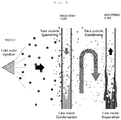
- FIG. 5 is a diagram for describing a principle of the two-phase heat transfer mechanism which is used in the nuclear reactor according to the exemplary embodiment of the present invention.
- a basic heat exchange principle in most of the existing heat exchangers is to pass a heat exchange medium through a channel isolated from the outside and directly exchange heat between a heat exchange medium in the channel and another heat exchange medium outside the channel, having a wall surface of the channel provided therebetween, thereby performing the heat transfer. That is, for example, an air cooling type heat exchanger form which is configured to make high-temperature cold water flow inside the channel and make low-temperature air flow outside the channel to allow the low-temperature air to absorb the heat of the high-temperature cold water has been most widely used.
- a heterogeneous heat exchanger form which is configured to make high-temperature oil flow in one side thereof and the low-temperature cold water flow in the other side thereof to allow the low-temperature cold water to absorb the heat of the high-temperature oil has been widely used as well.
- the heat exchange portion according to the exemplary embodiment of the present invention exchanges heat depending on a totally different principle therefrom.
- the heat exchange portion according to the exemplary embodiment of the present invention using the two-phase heat transfer mechanism basically includes three components, i.e., a releasing tube (left tube in FIG. 5 ) in which the high-temperature heat exchange medium flows, an absorbing tube (right tube in FIG. 5 ) in which the low-temperature heat exchange medium flows, and a nozzle through which other heat exchange media (cold water in FIG. 5 or other liquids) are sprayed to the two tubes.
- a releasing tube left tube in FIG. 5
- an absorbing tube right tube in FIG. 5
- other heat exchange media cold water in FIG. 5 or other liquids
- the high-temperature heat exchange medium flows in the releasing tube and the low-temperature heat exchange medium flows in the absorbing tube.
- the two tubes adhere to each other to transfer heat from a high temperature side to a low temperature side through a wall surface of the tube.
- the two tubes are spaced apart from each other at an appropriate interval.
- the nozzle is provided at the releasing tube side to spray the cold water to the releasing tube. If the cold water is sprayed and water drops thereof approach or contact an outer surface of the releasing tube, the water drops of the cold water instantly absorb heat of the high-temperature heat exchange medium within the releasing tube and thus are quickly evaporated. That is, the water drops of the cold water quickly absorb a large amount of evaporation heat at the outer surface of the releasing tube and thus the rapid cooling phenomenon (tube outside : quenching) happens and the high-temperature heat exchange medium releases heat while taking its own heat away as the evaporation heat of the water drops inside the releasing tube and is cooled and thus the condensation phenomenon (tube inside : condensation) happens.
- the cold water around the releasing tube is completely evaporated and becomes a steam state.
- the steam contacts the absorbing tube which is spaced apart from the releasing tube.
- the heat of the steam is instantly taken away to the low-temperature heat exchange medium within the absorbing tube and thus the steam is condensed, such that the steam is formed at the outer surface of the absorbing tube.
- the releasing tube and the absorbing tube are spaced apart from each other, the separate heat exchange medium (cold water in an example of FIG. 5 ) sprayed from the nozzle performs the heat transfer while being changed to gas phase - liquid phase in such a manner that the heat exchange medium is sprayed in a liquid phase, evaporated near the releasing tube to be in a gas phase, and condensed near the absorbing tube and again returns to the liquid phase.
- the separate heat exchange medium cold water in an example of FIG. 5
- the safety system according to the exemplary embodiment of the present invention uses the two-phase heat transfer scheme to allow the coolant to absorb heat, thereby realizing the cooling faster and more efficiently than the existing nuclear reactor safety system.
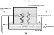
- FIGS. 6A and 6B are diagrams illustrating a saturated steam pressure space forming principle of a nuclear reactor according to an exemplary embodiment of the present invention.
- FIG. 6 schematically illustrates the residual heat removing portion illustrated in FIG. 3 . If the heat exchange portion provided in the residual heat removing portion of the present invention is compared with the conventional heat exchanger for removing residual heat illustrated in FIG. 2 , there is a difference in that first, in addition to a channel (the primary heat exchanger in FIG. 6 ) through which the high-temperature fluid is distributed, a channel (the secondary heat exchanger in FIG. 6 ) through which the low-temperature fluid and a flow path are distributed are further provided, and second, a coolant accommodating structure having the path, through which the high-temperature fluid is distributed, accommodated therein.
- a coolant accommodating structure having the path, through which the high-temperature fluid is distributed, accommodated therein.
- the spray-type heat exchanger may be operated in the state as illustrated in FIG. 6A .
- the state of FIG. 6A corresponds to the state of FIG. 5A . If the high-temperature fluid is distributed in the primary heat exchanger in this state, similarly to the heat exchanger for removing residual heat illustrated in FIG. 2 , heat is transferred to the coolant around the primary heat exchanger in which the high-temperature fluid is distributed to boil the coolant, thereby cooling down the high-temperature fluid.
- the coolant accommodating structure according to the exemplary embodiment of the present invention is different from the conventional coolant accommodating structure.
- the coolant accommodating structure includes the airtight container portion and the water tank, wherein the airtight container portion having the primary heat exchanger, in which the high-temperature fluid is distributed, accommodated therein has a form in which a lower part thereof is open and an upper part thereof is closed and the water tank having the top-opened box form is provided on the lower part of the airtight container portion. That is, the airtight container portion is further provided in the water tank of the conventional heat exchanger for removing residual heat. At this time, as illustrated, the airtight container portion needs to be fully filled with the liquid-state coolant so that the airtight container portion does not have an empty space in an initial state.
- the upper part of the airtight container portion is closed, and therefore the air bubbles are collected on the upper part of the airtight container portion without being lost.
- the space filled with steam having a saturated steam pressure is provided on the upper part of the airtight container portion as illustrated in FIG. 6B (in other words, the state of FIG. 6B corresponds to that of FIG. 5B ).
- the liquid-state coolant is pushed as much as the saturated steam pressure space is formed, that is, as indicated by the thin arrow in FIG. 6B , a water level in the airtight container portion drops and a water level between the airtight container portion and the water tank rises.
- heat may be transferred from the high-temperature fluid in the primary heat exchanger to the low-temperature fluid in the secondary heat exchanger by the two-phase heat transfer mechanism.
- the primary heat exchanger (high-temperature fluid distribution) in FIG. 6 corresponds to the releasing tube in FIG. 5
- the secondary heat exchanger (low-temperature fluid distribution) in FIG. 6 corresponds to the absorbing tube in FIG. 5
- the flow path in FIG. 6 corresponds to the nozzle in FIG. 5 . That is, in the structure illustrated in FIG. 6 , the heat transfer from the high-temperature fluid to the low-temperature fluid according to the above-described two-phase heat transfer principle can be made smoothly.
- the two-phase heat transfer is made by the evaporation heat and the condensation heat of the coolant, the efficiency is much higher than the heat transfer in the general fluid, that is, the convective heat transfer. That is, the two-phase heat transfer method can realize the heat transfer much faster and more effectively than the conventional heat transfer method.
- the coolant sprayed from the flow path (corresponding to the nozzle in FIG. 5 ) is evaporated around the primary heat exchanger (corresponding to the releasing tube in FIG. 5 ) and the heat transfer is made by the phenomenon that the coolant is condensed around the secondary heat exchanger (corresponding to the absorbing tube in FIG. 5 ), such that it is advantageous that there is the amount of coolant steam around the primary heat exchanger and the secondary heat exchanger as much as possible.
- the higher the ratio of non-condensed gases such as air around the primary heat exchanger and the secondary heat exchanger, the lower the two-phase heat transfer efficiency.
- the space filled with gas that is, the coolant steam due to the boiling of the coolant in the state in which no space filled with gas (state of FIG. 6A ) is originally present is generated, such that the space becomes the space in which the coolant steam forms the saturated steam pressure and is full.
- a ratio of the non-condensed gas is minimized around the primary heat exchanger and the secondary heat exchanger in the space above the water level of the liquid-state coolant in the airtight container portion, such that the two-phase heat transfer efficiency in the state of FIG. 6B is maximized.
- the boiling of the coolant is still used in the part immersed in the liquid-state coolant, and the cooling is performed using the two-phase heat transfer in a part exposed to the steam, thereby realizing the cooling efficiency and rate much higher than before.
- the two-phase heat transfer efficiency can be increased to the maximum possible.
- FIG. 7 illustrates the nuclear reactor according to the exemplary embodiment of the present invention.
- the nuclear reactor according to the exemplary embodiment of the present invention also includes the nuclear reactor driving system and the nuclear reactor safety system.
- the nuclear reactor driving system is configured to include a nuclear reactor vessel 152 accommodating a nuclear reactor core 151 and a steam generator 153 to which a steam pipe 154 and a water supply pipe 155 are connected.
- the steam generator may be integrally formed within the nuclear reactor vessel or the steam generator may be provided outside the nuclear reactor vessel. Therefore, the nuclear reactor driving system is not limited to the illustrated form but may be formed in any form. An operation of each part of the nuclear reactor driving system will be described below in more detail.
- the nuclear reactor core 151 is a core portion of the nuclear reactor and is a part of causing the nuclear fission in which an atomic nucleus of nuclear fuel is split into two by being combined with a neutron to generate heat energy. That is, generally, the nuclear reactor core 151 is called a bundle of fuel rods which is nuclear fuel of the reactor. Further, generally, the nuclear reactor core 151 includes a nuclear reactor output control rod, in which the nuclear reactor output control rod is vertically movably inserted into the nuclear reactor core 151 to control how much the nuclear fission of the nuclear fuel is made depending on the inserted degree of the nuclear reactor output control rod, and thus acts to control the output of the nuclear reactor 100.
- the nuclear reactor vessel 152 accommodates the nuclear reactor core 151 while being sealed off from the outside. As described above, since the nuclear reactor output control rod needs to be controlled to vertically move, a portion of the upper end of the nuclear reactor output control rod is generally provided to be exposed outside the nuclear reactor vessel 152. In this respect, the nuclear reactor core 151 is naturally disposed under the nuclear reactor vessel 152. At this time, the coolant is accommodated in the reactor vessel 152 and thus the heat energy generated from the reactor core 151 is absorbed into the coolant.
- the coolant absorbs the heat energy generated from the nuclear reactor core 151 to act to cool the nuclear reactor core 151 and transfers the heat absorbed by the coolant to the outside, thereby generating power (hereinafter, which will be described below in more detail in the steam generator 153).
- the coolant cold water, that is, water is generally used, which will be described below in more detail.
- the heat exchange media distributed in each part may be mixed due to the opening of a circulation channel which is in a closed state at ordinary times, etc., when the nuclear reactor safety system is operated, and therefore the heat exchange medium or the coolant which is used in each of all parts of the nuclear reactor is generally used steadily as the cold water.
- the steam generator 153 is formed in the heat exchanger form and is provided inside the nuclear reactor vessel 152.
- the coolant operated as the heat exchange medium is distributed inside the steam generator 153 and the steam generator 153 is supplied with heat from the coolant inside the nuclear reactor vessel 152 around the steam generator 153. Therefore, the coolant distributed inside the steam generator 153 absorbs heat and the evaporation happens.
- the coolant which is in the high-temperature, high-pressure gas phase is discharged to the steam pipe 154 to operate a turbine. After the turbine is operated, the condensed coolant is again supplied to the steam generator 153 through the water supply pipe 155 and thus is circulated.
- the steam pipe 154 and the water supply pipe 155 are each provided with a steam pipe isolation valve 154a and a water supply pipe isolation valve 155a and thus are blocked from the outside at the time of an emergency situation.
- the coolant inside the nuclear reactor vessel 152 is naturally circulated. This will be described below in more detail.
- the heat energy generated from the nuclear reactor core 151 is absorbed into the coolant, the high-temperature coolant rises.
- the high-temperature coolant reaches the steam generator 153 which is disposed over the nuclear reactor core 151, the coolant in the steam generator 153 and the high-temperature coolant exchange heat with each other. That is, the coolant in the steam generator 153 absorbs heat from the high-temperature coolant. Therefore, the high-temperature coolant has the reduced temperature while passing through the steam generator 153 and thus falls. The so falling coolant again absorbs the heat energy generated from the nuclear reactor core 151 again, such that the natural circulation convection is made.
- the foregoing nuclear reactor driving system may be commonly included in the existing large or small (integrated) reactor.
- the driving system configured as described above is operated and thus the nuclear reactor produces power.
- the operation of the nuclear reactor has no problem only by the driving system.
- the nuclear reactor vessel 152 is damaged and thus the coolant in the nuclear reactor vessel 152 is leaked, the heat energy generated from the nuclear reactor core 151 may not be absorbed into a sufficient amount of coolant. Therefore, the temperature around the nuclear reactor core 151 excessively rises and thus more serious damage such as melting of parts may occur.
- the nuclear reactor has a great effect on environment such as radioactivity leakage and therefore safety is important above all. Therefore, if the coolant is leaked due to the damage of the nuclear reactor vessel 152, a safety system to quickly cool the nuclear reactor vessel 152, etc., is essential.
- the safety system is operated only when receiving a separate control command such as an operator's manipulation, when the operator of the nuclear reactor does not issue a command in time at the time of the occurrence of accidents due to the problems that he/she is absent, wounded, or the like, the danger of the accident is largely increased. Further, even in the case of the system which is automatically controlled by an electron control, etc., when the safety system is damaged due to the hot heat generated due to the damage of the nuclear reactor, the safety system may not be correctly operated. Therefore, when the nuclear reactor is damaged and the coolant is leaked, a passive safety system which is mechanically operated upon the change in physical environment is necessarily provided. Further, many studies on the passive safety system have been conducted in the past. However, the existing passive safety system has the following problems.
- the exemplary embodiment of the present invention may appropriately cope with the various occurrence situations of accidents of nuclear reactors using one system and may configure the safety systems (that is, devices for cooling a nuclear reactor) in completely passive type and thus there is no need for the separate control command of the operator. As a result, the fast cooling may be made when the nuclear reactor is damaged.
- the nuclear reactor according to the exemplary embodiment of the present invention mostly uses the two-phase heat transfer scheme to perform the cooling and performs the cooling while the coolant appropriately moves within the containment vessel divided into several spaces at the time of the occurrence of accidents to perform the faster and more efficient cooling than before.
- the safety system according to the exemplary embodiment of the present invention has a configuration much simpler than that of the existing passive safety system to greatly reduce the volume of the nuclear reactor, such that it is very suitable for the small nuclear reactor of which the demand has been gradually expanded recently.
- the nuclear reactor safety system largely includes a first containment vessel 110 and a second containment vessel 120, and further includes a containment vessel through tube 111 for the purpose of movement of the coolant, a coolant injection pipe 112, or the like, and a residual heat removing device 130 for removing residual heat is provided.
- a first space V1 inside the first containment vessel (110) accommodates gases and the nuclear reactor driving system. That is, the space in the first containment vessel 110, that is, the first space V1 corresponds to the energy release space ERS in the conceptual structure (see item I of FIG. 3 ) of the nuclear reactor of the present invention described above.
- the second containment vessel 120 is disposed in close contact with the first containment vessel 110 and has a horizontal barrier 125 provided therein so that the inner space thereof is divided into a lower second space V2 and an upper third space V3 to accommodate the coolant in the second space V2.
- the second space V2 of the lower part of the second containment vessel 120 corresponds to the energy absorbing space EAS in the conceptual structure (see item I of FIG. 3 ) of the nuclear reactor according to the exemplary embodiment of the present invention described above.
- the third space V3 of the upper part of the second containment vessel 120 corresponds to the energy transfer space ETS in the conceptual structure (see item I of FIG. 3 ) of the nuclear reactor according to the exemplary embodiment of the present invention described above.
- the first containment vessel 110 and the second containment vessel 120 configuring the nuclear reactor safety system have the energy release space (ERS), the energy absorbing space (EAS), and the energy transfer space (ETS) provided therein and selectively distributes the coolant in the nuclear reactor safety system in response to the thermal hydraulic condition changed in response to the change in pressure in the nuclear reactor driving system and whether the coolant is leaked, thereby cooling down the nuclear reactor driving system.
- ERS energy release space
- EAS energy absorbing space
- ETS energy transfer space
- One end of the containment vessel through pipe 111 is disposed in the first space V1 and the other end thereof communicates with the second space V2 and the containment vessel through pipe 111 includes a containment vessel through valve 111v.
- the containment vessel through pipe 111 corresponds to a passage in the conceptual structure (see item I of FIG. 3 ) of the nuclear reactor according to the exemplary embodiment of the present invention described above.
- one end of the coolant injection pipe 112 is disposed in the third space V3 and the other end thereof communicates with the first space V1 and the coolant injection pipe 112 includes a coolant injection valve 112v.
- the movement of the coolant or the steam between the first space V1 and the second space V2 by the containment vessel through pipe 111 moves the coolant or the steam between the third space V3 and the first space V1 by the coolant injection pipe 112.
- the movement of the coolant between the second space V2 and the third space V3 is made by the coolant spray pipe 133.
- the movement of the coolant or the steam is naturally made by the state (liquid state / gas state) of the coolant in the first, second, and third spaces V1, V2, and V3, a pressure difference, a water head difference, or the like without requiring the active operation of the separate control device. That is, the operation of selectively distributing the coolant in the nuclear reactor safety system in response to the thermal hydraulic conditions changed depending on the change in pressure within the nuclear reactor driving system and whether the coolant is leaked to cool down the nuclear reactor driving system is naturally realized.
- the residual heat removing device 130 is provided in the third space V3 and is connected to the nuclear reactor driving system to transfer the heat released from the nuclear reactor driving system to the coolant and transfer the heat absorbed into the coolant to the outside. Describing the configuration of the residual heat removing device 130 in more detail, the residual heat removing device 130 includes a heat exchange vessel 134 that includes a primary heat exchanger 131, a secondary heat exchanger 132, a coolant spray pipe 133, and a coolant flow path 134a and a heat exchange vessel outer cylinder 135.
- the primary heat exchanger 131 is connected to the nuclear reactor driving system to distribute the coolant in the nuclear reactor driving system, thereby dissipating heat.
- the primary heat exchanger 131 corresponds to the primary heat exchanger or the releasing tube in the conceptual structure (see item I of FIGS. 3 and 4 ) of the nuclear reactor according to the exemplary embodiment of the present invention and the main principles (see item II of FIGS. 5 and 6 ) of the present invention described above.
- the secondary heat exchanger 132 is disposed to be close to the primary heat exchanger 131 and distributes the residual heat absorbing coolant to absorb heat. At this time, the secondary heat exchanger 132 corresponds to the secondary heat exchanger or the absorbing tube in the conceptual structure (see item I of FIGS. 3 and 4 ) of the nuclear reactor according to the exemplary embodiment of the present invention and the main principles (see item II of FIGS. 5 and 6 ) of the present invention described above.
- the coolant spray pipe 133 is connected to the second space V2 and sprays the supplied coolant to the primary heat exchanger 131. At this time, the coolant spray pipe 133 corresponds to the flow path or the nozzle in the conceptual structure (see item I of FIGS. 3 and 4 ) of the nuclear reactor according to the exemplary embodiment of the present invention and the main principles (see item II of FIGS. 5 and 6 ) of the present invention described above.
- the heat exchange vessel 134 has the airtight container form in which a coolant is accommodated.
- An upper part of the heat exchange vessel 134 is provided with the primary heat exchanger 131 and the secondary heat exchanger 132 and a lower part thereof is provided with the coolant flow path 134a communicating with the second space V2 and having the coolant distributed therethrough.
- the coolant spray pipe 133 corresponds to the airtight container portion in the conceptual structure (see item I of FIGS. 3 and 4 ) of the nuclear reactor according to the exemplary embodiment of the present invention and the main principles (see item II of FIG. 6 ) of the present invention described above.
- the heat exchange vessel outer cylinder 135 is provided to surround the heat exchange vessel 134 to secure the water level of the coolant at which the lower end of the coolant flow path 134a is immersed in the coolant, and thus is configured to accommodate and distribute the coolant.
- the heat exchange vessel outer cylinder 135 corresponds to the water tank in the main principles (see item II of FIG. 6 ) of the present invention described above.
- the water tank illustrated in FIG. 6 merely serves to accommodate the coolant, but the heat exchange vessel outer cylinder 135 serves to more smoothly control the water level of the coolant due to the shape features.
- the heat exchange vessel outer cylinder 135 basically has a shape corresponding to the heat exchange vessel 134 and is formed to surround the heat exchange vessel 134. More specifically, the heat exchange vessel outer cylinder 135 is formed to be larger than the heat exchange vessel 134 so that an inner wall of the heat exchange vessel outer cylinder 135 and an outer wall of the heat exchange vessel 134 are spaced apart from each other at a predetermined interval. In addition, the heat exchange vessel outer cylinder 135 has the upper part opened and the lower part closed so that the coolant is distributed to the upper part.
- the heat exchange vessel outer cylinder 135 surrounds the heat exchange vessel 134, such that the coolant discharged from the heat exchange vessel 134 is first filled in the space between the outer wall of the heat exchange vessel 134 and the inner wall of the heat exchange vessel outer cylinder 135. At this time, since the lower part of the heat exchange vessel outer cylinder 135 is closed, the coolant may not exit from the space before the level of the coolant filled in the space rises to the opened upper part of the heat exchange vessel outer cylinder 135.
- the coolant discharged from the heat exchange vessel 134 is filled in the space between the outer wall of the heat exchange vessel 134 and the inner wall of the heat exchange vessel outer cylinder 135 just as it is to secure the appropriate water level of the coolant so that the water head difference from the water level of the coolant in the heat exchange vessel 134 is not so large.
- the coolant discharged from the heat exchange vessel 134 spreads into the third space V3, such that it is difficult to make the water level of the coolant high.
- a structure such as a vertical barrier may be formed on the lower part of the heat exchange vessel 134 to partially partition the space in the third space V3. Even in this case, in consideration of the volume of the third space V3, since the absolute amount of the coolant discharged from the heat exchange vessel 134 is considerably insufficient, it is apparent that the water head difference between the water level of the coolant flowing out released from the third space V3 and the water level of the coolant in the heat exchange vessel 134 is considerably large.
- the pressure difference between the respective spaces has to be very large so that the water head difference can be maintained. That is, the process of discharging the coolant by the pressure at which the saturated steam pressure space is formed within the heat exchange vessel 134 may not be smoothly performed in the environment that the water head difference is large.
- the coolant discharged from the heat exchange vessel 134 is preferentially filled in the space between the heat exchange vessel 134 and the heat exchange vessel outer cylinder 135.
- the volume of the space itself is not so large (relatively as compared to the case where the coolant is discharged to the third space V3), a much higher water level can be easily achieved even by a much less coolant. That is, the water level of the coolant in the heat exchange vessel 134 and the water level of the coolant in the space between the heat exchange vessel 134 and the heat exchange vessel outer cylinder 135 may be balanced with the relatively much less water head difference. Therefore, the formation of the saturated steam pressure space and the discharge of the coolant in the heat exchange vessel 134 can be made more stably and smoothly.
- the two-phase heat transfer principle can realize much faster and more effective cooling than the existing nuclear reactor safety system, and the two-phase heat transfer phenomenon is always made in the saturated steam pressure space, thereby maximizing the two-phase heat transfer efficiency to the maximum possible.
- FIG. 8 illustrates each step of the method of operating a nuclear reactor according to the exemplary embodiment of the present invention illustrated in FIG. 7 .
- FIG. 8A illustrates a state in which the nuclear reactor is operating normally. That is, since overheat is not generated in the nuclear reactor driving system, all the heat generated from the nuclear reactor core 151 is used to evaporate the coolant in the steam generator 153 supplied to the water supply pipe 155. In addition, all of the steam in the steam generator 153 is discharged through the steam pipe 154 to rotate the external generator, thereby generating electric power. In this case, the nuclear reactor safety system does not operate and maintains the initial state.
- the initial state of the nuclear reactor safety system of the present invention is the state in which the coolant is filled in the third space V3 and the coolant is fully filled in the heat exchange vessel 134 in the residual heat removing portion 130 without any empty space.
- Starting the operation of the nuclear reactor safety system means that the nuclear reactor driving system is abnormally operated due to the intentional stop of the nuclear reactor driving system, the accidents of the nuclear reactor, etc. That is, prior to starting the operation of the nuclear reactor safety system, isolating which includes stopping the nuclear reactor driving system; and closing the steam pipe isolation valve 154v included in the steam pipe 154 and the water supply pipe isolation valve 155v included in the water supply pipe 155 is always performed.
- FIG. 8B illustrates the state in which the cooling of the nuclear reactor is being performed by moving the coolant in the nuclear reactor safety system due to the change in pressure in the nuclear reactor driving system as described above.
- the operation of the nuclear reactor safety system in the state as illustrated in FIG. 8 (B) includes a primary heat exchanger circulating step, a saturated steam pressure space forming step, a two-phase heat transfer step, and a residual heat removing step.
- the primary heat exchanger circulating step is performed in the following order. First, the steam generated by evaporating the coolant in the nuclear reactor driving system is introduced into the primary heat exchanger 131. Next, the steam introduced into the primary heat exchanger 131 is condensed by passing through the primary heat exchanger 131 to generate a coolant, and the generated coolant is re-introduced into the nuclear reactor vessel 152 to be circulated.
- the exemplary embodiment of FIG. 7 illustrates that the primary heat exchanger 131 is connected to the steam generator 153 in the nuclear reactor driving system. That is, in this case, the steam in the steam generator 153 is introduced into the primary heat exchanger 153.
- the channel connected to the primary heat exchanger 131 may be provided with a channel communicating with the nuclear reactor vessel 152 or the first space V1.
- the steam in the steam generator 153 may also be distributed to the primary heat exchanger 131 to be cooled.
- the present invention uses the two-phase heat transfer principle to cool down the steam (a two-phase heat transfer step).
- the device for forming the saturated steam pressure space (a saturated steam pressure space forming step) is configured to further maximize the two-phase heat transfer efficiency.
- the saturated steam pressure space forming step is performed in the following order. First, as described in the primary heat exchanger circulating step, if steam is introduced into the primary heat exchanger 131, the coolant accommodated in the heat exchange vessel 134 exchanges heat with the steam introduced into the primary heat exchanger 131 to be heated and boiled (the steam continues to be cooled down even in the step). As described above, the steam generated by boiling the coolant around the primary heat exchanger 131 is formed in the bubble form and collected on the upper part of the heat exchange vessel 134 by the density difference. As the amount of bubbles to be collected increases over time, the bubbles eventually form the space having the saturated steam pressure in the upper part of the heat exchange vessel 134.
- the saturated steam pressure space in which the bubbles are collected extends to the position where the primary heat exchanger 131 and the secondary heat exchanger 132 are disposed.
- the primary heat exchanger 131 and the secondary heat exchanger 132 are disposed in the space in which the coolant steam is saturated, that is, there is no non-condensed gas in the space around the primary heat exchanger 131 and the secondary heat exchanger 132.
- the two-phase heat transfer step is performed in the following order.
- the coolant supplied by the coolant spray pipe 133 is in contact with an outer surface of the primary heat exchanger 131 by being first sprayed to the outer surface while the saturated steam pressure space is formed as described above.
- the coolant spray pipe 133 corresponds to the nozzle of FIG. 5
- the primary heat exchanger 131 corresponds to the releasing tube of FIG. 5 .
- the coolant contacting the outer surface of the primary heat exchanger 131 absorbs the heat from the steam in the primary heat exchanger 131 to be evaporated and the steam in the primary heat exchanger 131 is condensed to generate the coolant.
- the steam generated by being evaporated from the outer surface of the primary heat exchanger 131 is in contact with the outer surface of the secondary heat exchanger 132.
- the secondary heat exchanger 132 corresponds to the absorbing tube of FIG. 5 .
- the steam contacting the outer surface of the secondary heat exchanger 132 discharges heat to the coolant in the secondary heat exchanger 132 to be condensed as the coolant, and the coolant in the secondary heat exchanger 132 is evaporated to generate steam.
- the present invention has the following advantages.
- the higher the ratio of the non-condensed gas within the space the lower the heat transfer efficiency becomes.
- the primary heat exchanger 131 and the secondary heat exchanger 132 are disposed within the space (that is, saturated steam pressure space) saturated with the coolant steam naturally formed by the saturated steam pressure forming step, such that the efficiency of the two-phase heat transfer is maximized.
- the residual heat removing step is performed in the following order.
- the coolant in the secondary heat exchanger 132 exchanges heat with the steam passing through the primary heat exchanger 131 by the two-phase heat transfer principle, such that the coolant absorbs heat to become steam.
- the residual heat is removed by discarding the heat of the steam to the outside. Specifically, first, the steam in the secondary heat exchanger 132 is discharged to the outside or is introduced into an external separate heat exchanger. Next, the external coolant is introduced into the secondary heat exchanger 132 or the coolant generated by being condensed in the external separate heat exchanger is re-introduced and circulated, such that the residual heat can be removed.
- auxiliary secondary heat exchanger 132a provided in the third space V3 is further provided on the channel through which the coolant discharged from the secondary heat exchanger 132 flows (as will be described below in more detail), such that the cooling may be partially performed in advance before being discharged to the outside by the coolant filled in the third space V3 during the safety system driving process.
- FIG. 3 or 7 illustrates the example in which the nuclear reactor according to the exemplary embodiment of the present invention is formed so that the first containment vessel 110 and the second containment vessel 120 are disposed under the surface of the water. That is, the nuclear reactor according to the exemplary embodiment of the present invention may be directly installed in a heat sink having heat capacity close to infinity, such as seawater or a water reservoir.
- a heat sink having heat capacity close to infinity, such as seawater or a water reservoir.
- an inlet and an outlet of the secondary heat exchanger 132 may be formed to be directly opened to the space filled with seawater or water of the water reservoir.
- the steam in the secondary heat exchanger 132 is discharged in the form of bubbles through the discharge end, so that heat can be conveniently discarded.
- the seawater or the water of the water reservoir is introduced into the secondary heat exchanger 132 through an inlet as much as the steam is discharged from the secondary heat exchanger 132, thereby newly performing the heat exchange.
- the secondary heat exchanger 132 may be connected to the external separate heat exchanger as described above.
- the external separate heat exchanger is provided in the heat sink such as the seawater or the water reservoir.
- the steam in the secondary heat exchanger 132 flows into the external separate heat exchanger through the discharge end and the separate heat exchanger discards heat to the heat sink, such that the steam is cooled to be condensed as the liquid-state coolant.
- the so condensed coolant is re-introduced through the inlet of the secondary heat exchanger 132 to be circulated, such that the residual heat may be removed.
- the nuclear reactor safety system may further include an auxiliary water supply pipe 116 to further perform a coolant auxiliary water supply step. More specifically, one end of the auxiliary water supply pipe 116 communicates with the lower part of the second space V2 and the other end thereof communicates with the steam generator 153, and an auxiliary water supply valve 116v is provided on the auxiliary water supply pipe 116. At this time, the coolant auxiliary water supply step has the process in which if the pressure of the second space V2 is higher than that in the steam generator 153, the auxiliary water supply valve 116v is open and thus the coolant in the second space V2 is supplied to the steam generator 153.
- the auxiliary steam release valve 131v may further be provided in the nuclear reactor safety system so that the auxiliary steam supply step to the saturated steam pressure space may be further performed. More specifically, the auxiliary steam release valve 131v is provided on the upper part of the primary heat exchanger 131 to auxiliarily supply steam to the space having the saturated steam pressure in the heat exchange vessel 134. At this time, the auxiliary steam supply step to the saturated steam pressure space has the process in which if the coolant auxiliary supplied to the steam generator 153 by the coolant auxiliary water supply step is evaporated to generate steam, the auxiliary steam release valve 131v is open to supply the steam in the steam generator 153 to the heat exchange vessel 134 to further form the space having the saturated steam pressure. As described above, the steam is further supplied to the saturated steam pressure space, such that the two-phase heat transfer between the primary heat exchanger 131 and the secondary heat exchanger 132 can be performed more efficiently.
- the operation of introducing steam due to the overheat generated in the nuclear reactor driving system into the primary heat exchanger 131 and cooling down and condensing the steam by the two-phase heat transfer between the primary heat exchanger 131 and the secondary heat exchanger 132 by the spray of the coolant supplied through the coolant spray pipe 133 to return to the nuclear reactor driving system so as to perform the circulation is described.
- the coolant supplied through the coolant spray pipe 133 may be a coolant separately supplied from the outside.
- the nuclear reactor safety system may further include a steam bypass pipe 114 and a Nuclear reactor vessel safe valve 157.
- One end of the steam bypass pipe 114 is connected to a channel through which the coolant is introduced from the steam generator 153 in the nuclear reactor driving system to the primary heat exchanger 131 and the other end thereof is connected to the containment vessel through pipe 111.
- the steam bypass pipe 114 is provided with a steam bypass valve 114v. If there is no steam bypass pipe 114, all the coolant steam in the steam generator 153 is distributed to the primary heat exchanger 131 to be used for cooling. However, if the operation failure of the nuclear reactor occurs, the temperature in the nuclear reactor rises very sharply, and the evaporation rate of the coolant and the steam generation amount in the steam generator 153 increase accordingly, such that the pressure in the steam generator 153 and the primary heat exchanger 131 is highly likely to excessively increase.
- the steam bypassed through the steam bypass pipe 114 serves to pressurize the pressure in the second space V2.
- the Nuclear reactor vessel safe valve 157 is provided in the nuclear reactor vessel 152 as illustrated to discharge the steam in the nuclear reactor vessel 152 to the first space V1 or the containment vessel through pipe 111.
- the step of performing the coolant pressurization spray is performed in the following order.
- the steam generated in the nuclear reactor driving system is introduced into the containment vessel through pipe 111 by at least one operation selected from the opening of the containment vessel through valve 111v, the opening of the steam bypass valve 114v, and the opening of the Nuclear reactor vessel safe valve 157.
- the containment vessel through valve 111v is naturally open by the pressure to make steam flow from the first space V1 into the second space V2 through the containment vessel through pipe 111 and make the steam pressurize the second space V2.
- the containment vessel through valve 111v is preferably a check valve type that permits only the flow from the first space V1 into the second space V2.
- the second space V2 is not pressurized without the steam bypass pipe 114 or the nuclear reactor safety valve 157.
- the steam bypass pipe 114 is connected to the containment vessel through pipe 111, when the steam bypass pipe 114 is provided, the steam in the steam generator 153 is introduced into the second space V2 through the containment vessel through pipe 111 to smoothly pressurize the second space V2.
- the nuclear reactor safety valve 157 is configured to discharge steam to the first space V1 or to discharge the steam to the containment vessel through pipe 111 as illustrated, when the steam is discharged to the first space V1, the steam flows into the second space V2 through the containment vessel through pipe 111 on the same principle as the leakage of the coolant and when the steam is discharged to the containment vessel through pipe 111, the steam naturally flows into the second space V2.
- the coolant in the second space V2 is introduced into the coolant spray pipe 133 by the pressurization due to the steam introduced through the containment vessel through pipe 111.
- the coolant spray valve 133v is opened by the pressure and thus the coolant is sprayed to the primary heat exchanger 131 and the secondary heat exchanger 132 through the coolant spray pipe 133, such that the above-described step of performing the two-phase heat transfer is performed.
- the coolant supplied to the coolant spray pipe 133 is not necessarily the coolant accommodated in any place of the nuclear reactor safety system, and therefore the supply operation of the coolant may be performed according to a separate control command.
- the coolant supplied to the coolant spray pipe 133 is the coolant accommodated in the second space V2.
- the supply operation takes place due to the change in pressure in the nuclear reactor driving system which occurs due to the overheat of the nuclear reactor. That is, in this case, no separate coolant supply or active control commands are required, which makes the operation convenient and the immediate accident-handling response much better.
- the nuclear reactor according to the exemplary embodiment of the present invention normally maintains the state as illustrated in FIG. 8A , but when the nuclear reactor overheats, the state changes to the state as illustrated in FIG. 8B , such that the cooling of the nuclear reactor driving system is made by the natural movement of the coolant in response to the change in pressure and thermal hydraulic condition. More specifically, the coolant moves to the residual heat removing device 130 in the third space V3 in the steam state, thereby discarding the heat of the first space V1, and the coolant in the second space V2 moves to the third space V3 so that the heat transfer can be smoothly performed.
- FIG. 8C illustrates the state in which such the nuclear reactor driving system is directly cooled.
- the step of directly cooling down the coolant is performed in the following order.
- the coolant generated by condensing the steam on the surface of the secondary heat exchanger 132 by the step of performing the two-phase heat transfer is discharged to the third space V3 through the coolant flow path 134a and is accommodated therein (as the space filled with saturated steam is formed on the upper part of the heat exchange vessel 134 in the step of forming the saturated steam pressure space, it is natural that the coolant pushed as much as the volume is also discharged together through the coolant flow path 134a).
- the coolant introduced into the heat exchange vessel 134 through the coolant spray pipe 133 is used for the two-phase heat transfer while being evaporated and condensed, and then finally condensed to be filled in the third space V3 as the liquid-state coolant state.
- the pressure of the empty space in the third space V3 gradually increases. That is, in the early stage of the occurrence of overheating of the nuclear reactor, the pressure of the first space V1 is highest and the pressure of the third space V3 is in a relatively low state. However, as the nuclear reactor is cooled down over time, the pressure of the first space V1 gradually decreases and the pressure in the third space V3 gradually increases due to the increase in the water level of the coolant in the third space V3.
- the nuclear reactor safety system may further include a steam release pipe 113 having one end communicating with the upper part of the first space V1 and the other end communicating with the upper part of the third space.
- the steam release pipe 113 is provided with a steam release valve 113v and distributes the steam in the first space V1 to the third space V3 to pressurize the pressure in the third space V3 when the steam release valve 113v is open. That is, when the pressure in the first space V1 increases, the steam release valve 113v is open. Then, some of the steam in the first space V1 is directly introduced into the third space V3, which serves to increase the pressure of the third space V3 while lowering the pressure of the first space V1. When the above process continues, the pressure in the first space V1 and the pressure in the third space V3 are balanced when it reaches a critical point.
- the coolant injection valve 112v is open by the water head difference between the first space V1 and the third space V3, such that the coolant accommodated in the third space V3 is introduced into the coolant injection pipe 112.
- the coolant introduced into the first space V1 through the coolant injection pipe 112 directly contacts the nuclear reactor vessel 152 to perform the cooling as illustrated in FIG. 8C .
- the lower part of the heat exchange vessel outer cylinder 135 is provided with a heat exchange vessel outer cylinder valve 135v to release the coolant filled in the heat exchange vessel outer cylinder 135 so that the heat exchange vessel outer cylinder 135 can serve as a siphon.
- a step of adjusting a water level of a coolant it is preferable to better perform a step of adjusting a water level of a coolant.
- the step of adjusting the water level of the coolant may be performed in the following order.
- the coolant is filled in the heat exchange vessel outer cylinder 135 by the step of directly cooling down the coolant, and thus the water level rises.
- the heat exchange vessel outer cylinder valve 135c is open, the coolant filled in the heat exchange vessel outer cylinder 135 is discharged to the third space V3 by the siphon principle until the water level between the third space V3 and the heat exchange vessel outer cylinder 135 becomes equal.
- the coolant may be a little more filled in the third space V3. Accordingly, it is possible to further increase the water head difference between the third space and the first space which leads to induce the step of directly cooling down the coolant. That is, as a result, the step of directly cooling down the coolant can be performed more smoothly by the step of adjusting the water level of the coolant.
- the coolant in the nuclear reactor driving system is in the state as illustrated in FIG. 8B in the early stage of the occurrence of overheating of the nuclear reactor and thus moves to the residual heat removing device 130, such that the coolant discards heat by the two-phase heat transfer and returns to the nuclear reactor driving system to be circulated, thereby performing the indirect cooling, and after a certain period of time elapses, the coolant is in the state as illustrated in FIG. 8C , such that the coolant comes into direct contact with the outer surface of the nuclear reactor vessel 152, thereby performing the direct cooling.
- the coolant comes into direct contact with the outer surface of the nuclear reactor vessel 152, the coolant is evaporated by absorbing heat from the nuclear reactor vessel 152. As the steam is filled in the first space V1, the pressure in the first space V1 rises again. As described above, if the pressure in the first space V1 and the pressure in the third space V3 are balanced, the coolant that has been filled in the third space V3 flows into the first space V1. In this manner, the coolant in the third space V3 flows into the first space V1 and thus if the pressure in the first space V1 rises again while the water head difference decreases, the step of directly cooling down the coolant naturally stops.
- the coolant that has been filled in the second space V2 during the process moves to the third space V3 (during the indirect cooling process) and the first space V1 (during the direct cooling process) in order, such that the water level of the coolant drops but the water level of the coolant in the first space V1 rises. Therefore, after any critical point, the coolant in the first space V1 flows into the second space V2 through the containment vessel through pipe 111 by the water head difference in coolant between the first space V1 and the second space V2, such that the second space V2 is again filled to some extent.
- This state is a state approaching the initial state of the occurrence of overheating of the nuclear reactor. Therefore, the coolant in the second space V2 is supplied to the residual heat removing device 130 through the coolant spray pipe 133 by the pressure in the first space V1, and the process of indirectly cooling down the nuclear reactor driving system by the two-phase heat transfer between the primary heat exchanger 131 and the secondary heat exchanger 132 using the supplied coolant, that is, the process of FIG. 8B is repeated. As the process of FIG. 8B proceeds, the process of directly cooling down the coolant is again performed if the cooling state again approaches the condition of FIG. 8C , and the processes of FIG. 8B and 8C are repeatedly performed alternately, such that the overheat generated in the nuclear reactor can be completely removed depending on the change in the pressure and thermal hydraulic conditions.
- the nuclear reactor safety system may further include a containment vessel depressurization pipe 115 to prevent the first space V1 from being over-pressurized during the process.
- the containment vessel depressurization pipe 115 has one end communicating with the lower part of the first space V1 and the other end communicating with the coolant injection pipe 112 and is provided with a containment vessel depressurization valve 115v.
- the containment vessel depressurization pipe 115 serves to distribute the steam in the first space V1 to the coolant injection pipe 112 so as to reduce the pressure in the first space V1.
- the method for operating a nuclear reactor may further include a step of depressurizing a containment vessel.
- the step of depressurizing a containment vessel is performed in the following order. After the step of directly cooling down the coolant, the coolant that is introduced into the first space V1 and is in direct contact with the nuclear reactor vessel 152 is evaporated by absorbing heat from the nuclear reactor vessel 152 to generate steam. The steam generated by absorbing heat from the nuclear reactor vessel 152 is filled in the first space V1 and thus the pressure in the first space V1 rises. Then, the containment vessel depressurization valve 115v is open by the pressure to introduce the steam in the first space V1 into the coolant injection pipe 112 through the containment vessel depressurization pipe 115, such that the overpressure in the first space V1 can be reduced.
- the containment vessel depressurization pipe heat exchanger 115a may be further provided on the containment vessel depressurization pipe 115.
- the steam in the first space V1 may be previously cooled down while passing through the containment vessel depressurization pipe heat exchanger 115a and may be introduced into the coolant injection pipe 112.
- the coolant in the coolant injection pipe 112 again flows into the first space V1 and comes into direct contact with the lower part of the nuclear reactor vessel 152 to perform the direct cooling.
- it is more preferable to previously cool down the steam by providing the containment vessel depressurization pipe heat exchanger 115a on the containment vessel depressurization pipe 115.
- the nuclear reactor vessel 152 may further include a coolant supplement pipe 156 for supplementing a coolant.
- a coolant supplement pipe 156 for supplementing a coolant.
- the coolant supplement pipe 156 is connected to the nuclear reactor vessel 152 and supplied with a coolant from the outside to supplement and supply the coolant into the nuclear reactor vessel 152. That is, if the coolant supplement pipe 156 is provided, a step of supplementing a coolant for supplementing the coolant supplied through the coolant supplement pipe 156 from the outside into the nuclear reactor vessel 152 may be performed.
- the nuclear reactor driving system further includes a first circulation valve 136v1 and a second circulation valve 136v2 to further supply the coolant to the steam generator 153, such that the coolant may be more smoothly circulated in the nuclear reactor.
- the first circulation valve 136v1 and the second circulation valve 136v2 are provided on the channel under the primary heat exchanger 131.
- the first circulation valve 136v1 is disposed inside the heat exchange vessel 134
- the second circulation valve 136v2 is disposed outside the heat exchange vessel 134.
- a step of supplementing a coolant into a steam generator for supplementing the coolant supplied from the third space V3 through the first circulation valve 136v1 and the second circulation valve 136v2 to the steam generator 153 may be performed, such that the coolant in the nuclear reactor may be more smoothly circulated.
Landscapes
- Physics & Mathematics (AREA)
- Engineering & Computer Science (AREA)
- Plasma & Fusion (AREA)
- General Engineering & Computer Science (AREA)
- High Energy & Nuclear Physics (AREA)
- Structure Of Emergency Protection For Nuclear Reactors (AREA)
Applications Claiming Priority (2)
| Application Number | Priority Date | Filing Date | Title |
|---|---|---|---|
| KR20150054557 | 2015-04-17 | ||
| PCT/KR2016/003932 WO2016167593A1 (ko) | 2015-04-17 | 2016-04-15 | 자가진단 사고대처 무인 원자로 |
Publications (3)
| Publication Number | Publication Date |
|---|---|
| EP3285262A1 true EP3285262A1 (de) | 2018-02-21 |
| EP3285262A4 EP3285262A4 (de) | 2018-11-21 |
| EP3285262B1 EP3285262B1 (de) | 2022-03-30 |
Family
ID=56949905
Family Applications (1)
| Application Number | Title | Priority Date | Filing Date |
|---|---|---|---|
| EP16780316.2A Active EP3285262B1 (de) | 2015-04-17 | 2016-04-15 | Selbstdiagnose und handhabung von unfällen in einem unbemannten kernreaktor |
Country Status (6)
| Country | Link |
|---|---|
| US (1) | US10811148B2 (de) |
| EP (1) | EP3285262B1 (de) |
| JP (1) | JP6633647B2 (de) |
| KR (1) | KR101654096B1 (de) |
| CN (1) | CN107533870B (de) |
| WO (1) | WO2016167593A1 (de) |
Families Citing this family (13)
| Publication number | Priority date | Publication date | Assignee | Title |
|---|---|---|---|---|
| KR102216695B1 (ko) * | 2018-09-03 | 2021-02-18 | 한국원자력연구원 | 노심 용융물 냉각 장치 |
| KR102274079B1 (ko) * | 2019-12-09 | 2021-07-07 | 한국원자력연구원 | 원자로의 피동무한냉각 구조체 및 그 작동방법 |
| KR102363832B1 (ko) * | 2020-04-17 | 2022-02-16 | 한국원자력연구원 | 원자로의 격납 용기 냉각 시스템 및 그 냉각 방법 |
| KR102352152B1 (ko) * | 2020-04-29 | 2022-01-19 | 한국원자력연구원 | 밸브 개폐 장치 및 이를 구비한 원자로의 피동무한 냉각 구조체 |
| KR102430312B1 (ko) * | 2020-05-22 | 2022-08-08 | 한국원자력연구원 | 미생물 부착 억제 장치 및 이를 포함하는 원자로의 피동냉각 구조체 |
| KR102369045B1 (ko) * | 2020-06-01 | 2022-03-02 | 한국원자력연구원 | 원자로 냉각 구조체 |
| KR102364895B1 (ko) * | 2020-06-01 | 2022-02-18 | 한국원자력연구원 | 원자로 냉각 구조체 |
| CN111863291B (zh) * | 2020-07-27 | 2025-05-09 | 中山大学 | 一种带辅助动力的自然循环系统及热汽泡驱动模块 |
| KR102381886B1 (ko) * | 2020-08-06 | 2022-04-04 | 한국원자력연구원 | 원자로 장기 냉각 계통 |
| CN112216413B (zh) * | 2020-09-04 | 2023-11-03 | 国家电投集团科学技术研究院有限公司 | 非能动余热导出系统、方法和具有该系统的核反应堆 |
| KR102574058B1 (ko) * | 2021-03-04 | 2023-09-04 | 한국원자력연구원 | 원자로의 피동무한냉각 구조체 및 그 작동방법 |
| KR102643962B1 (ko) * | 2022-03-10 | 2024-03-05 | 한국수력원자력 주식회사 | 소형원자로 냉각시스템 및 냉각방법 |
| CN119049744A (zh) * | 2024-08-23 | 2024-11-29 | 杭州大热若寒科技有限责任公司 | 一种热管冷却的小型模块化反应堆安全壳冷却装置及方法 |
Family Cites Families (26)
| Publication number | Priority date | Publication date | Assignee | Title |
|---|---|---|---|---|
| JPH04254795A (ja) * | 1991-01-30 | 1992-09-10 | Toshiba Corp | 原子力発電所の冷却設備 |
| CA2095494C (en) * | 1992-06-10 | 1998-08-11 | Ron C. Lee | Cooling method and apparatus |
| US5426681A (en) * | 1994-01-04 | 1995-06-20 | General Electric Company | Boiling water reactor with combined active and passive safety systems |
| FR2725508B1 (fr) | 1994-10-05 | 1997-01-03 | Commissariat Energie Atomique | Dispositif de controle du flux de chaleur par vanne thermique |
| JP2001228280A (ja) | 2000-02-21 | 2001-08-24 | Hitachi Ltd | 原子炉 |
| JP2002156485A (ja) * | 2000-11-15 | 2002-05-31 | Hitachi Ltd | 原子炉 |
| JP2006138744A (ja) | 2004-11-12 | 2006-06-01 | Mitsubishi Heavy Ind Ltd | 原子炉の冷却装置 |
| KR100906717B1 (ko) | 2007-08-28 | 2009-07-07 | 한국원자력연구원 | 고온가스로의 노심 잔열제거를 위한 공기/물 복합형 피동원자로 공동 냉각장치 |
| US8687759B2 (en) * | 2007-11-15 | 2014-04-01 | The State Of Oregon Acting By And Through The State Board Of Higher Education On Behalf Of Oregon State University | Internal dry containment vessel for a nuclear reactor |
| US8891723B2 (en) * | 2007-11-15 | 2014-11-18 | State of Oregon Acting by and Through The State Board of Higher Education on Behalf or Oregon State University, The Oregon State University | Stable startup system for a nuclear reactor |
| US8437446B2 (en) * | 2008-11-17 | 2013-05-07 | Nuscale Power, Llc | Steam generator flow by-pass system |
| JP5964029B2 (ja) * | 2011-10-26 | 2016-08-03 | 三菱重工業株式会社 | 蒸気発生器の補助給水弁制御装置 |
| KR101297101B1 (ko) * | 2011-11-01 | 2013-08-19 | 한국원자력연구원 | 원자로의 잔열 제거 장치 |
| WO2013081148A1 (ja) | 2011-12-02 | 2013-06-06 | 三菱重工業株式会社 | 流体冷却装置、静的除熱装置、流体冷却装置を備えた原子力プラント及び静的除熱装置を備えた原子力プラント |
| FR2985846B1 (fr) | 2012-01-18 | 2014-03-14 | Dcns | Module immerge de generation d'energie electrique |
| FR2985841B1 (fr) * | 2012-01-18 | 2014-02-21 | Technicatome | Systeme d'evacuation de la puissance residuelle d'un reacteur nucleaire a eau sous pression |
| WO2014099101A2 (en) * | 2012-10-04 | 2014-06-26 | Holtec International, Inc. | Shutdown system for a nuclear steam supply system |
| KR101404647B1 (ko) | 2012-05-21 | 2014-06-09 | 한국과학기술원 | 가압경수로의 피동형 원자로 및 격납용기 응축시스템 |
| US9275761B2 (en) | 2012-06-13 | 2016-03-01 | Westinghouse Electric Company Llc | Small modular reactor safety systems |
| KR101364646B1 (ko) * | 2012-07-30 | 2014-02-19 | 한국원자력연구원 | 소형 안전보호용기를 적용한 피동안전 시스템 및 이를 구비하는 일체형 원자로 |
| KR20140067287A (ko) * | 2012-11-26 | 2014-06-05 | 한국원자력연구원 | 원자로건물 피동 살수 계통 |
| JP6004438B2 (ja) | 2013-03-18 | 2016-10-05 | 日立Geニュークリア・エナジー株式会社 | 原子炉冷却システム |
| KR101463440B1 (ko) | 2013-04-22 | 2014-11-21 | 한국원자력연구원 | 피동안전설비 및 이를 구비하는 원전 |
| KR101479001B1 (ko) | 2013-06-11 | 2015-01-05 | 한국원자력연구원 | 피동잔열제거계통의 배기설비 |
| US9768221B2 (en) | 2013-06-27 | 2017-09-19 | Taiwan Semiconductor Manufacturing Company, Ltd. | Pad structure layout for semiconductor device |
| CN104966536B (zh) * | 2015-07-14 | 2017-06-20 | 西安交通大学 | 一种以导热油为热流体的高温工质换热试验系统及方法 |
-
2015
- 2015-07-07 KR KR1020150096370A patent/KR101654096B1/ko active Active
-
2016
- 2016-04-15 EP EP16780316.2A patent/EP3285262B1/de active Active
- 2016-04-15 JP JP2017552881A patent/JP6633647B2/ja active Active
- 2016-04-15 US US15/555,467 patent/US10811148B2/en active Active
- 2016-04-15 CN CN201680022514.4A patent/CN107533870B/zh active Active
- 2016-04-15 WO PCT/KR2016/003932 patent/WO2016167593A1/ko not_active Ceased
Also Published As
| Publication number | Publication date |
|---|---|
| US10811148B2 (en) | 2020-10-20 |
| EP3285262A4 (de) | 2018-11-21 |
| CN107533870B (zh) | 2019-11-08 |
| WO2016167593A1 (ko) | 2016-10-20 |
| CN107533870A (zh) | 2018-01-02 |
| US20180061514A1 (en) | 2018-03-01 |
| JP2018513374A (ja) | 2018-05-24 |
| JP6633647B2 (ja) | 2020-01-22 |
| EP3285262B1 (de) | 2022-03-30 |
| KR101654096B1 (ko) | 2016-09-07 |
Similar Documents
| Publication | Publication Date | Title |
|---|---|---|
| EP3285262B1 (de) | Selbstdiagnose und handhabung von unfällen in einem unbemannten kernreaktor | |
| KR101619075B1 (ko) | 포화증기압을 이용한 분사식 냉각계통을 포함하는 원자로 | |
| US10134493B2 (en) | Reactor and operating method for the reactor | |
| KR101463440B1 (ko) | 피동안전설비 및 이를 구비하는 원전 | |
| EP2862176B1 (de) | Kleine modulare reaktorsicherheitssysteme | |
| US20180350472A1 (en) | Passive safe cooling system | |
| US6718001B2 (en) | Nuclear reactor | |
| KR101731817B1 (ko) | 사이펀 원리를 이용한 냉각계통을 가지는 원자로 및 그 동작 방법 | |
| JP5690202B2 (ja) | 原子炉の崩壊熱除去装置 | |
| EP2973594B1 (de) | Vorrichtung zur passiven kühlung eines kernkraftwerks-kühlmittelbehälters | |
| KR101250479B1 (ko) | 안전보호용기를 구비한 피동형 비상노심냉각설비 및 이를 이용한 열 전달량 증가 방법 | |
| KR101559017B1 (ko) | 중대사고방지 무인사고대처 원자로 및 그 동작 방법 | |
| US10706974B2 (en) | Passive cooling system of containment building and nuclear power plant comprising same | |
| WO2014133658A1 (en) | Pressurized water reactor depressurization system | |
| KR102546736B1 (ko) | 2단 열교환에 의한 자연순환 냉각계통을 가지는 원자로 및 그 작동방법 | |
| CN113593733A (zh) | 一种非能动钢制安全壳热量导出系统 | |
| KR101505475B1 (ko) | 피동격납부냉각계통 및 이를 구비하는 원전 | |
| KR101564553B1 (ko) | 무인 원자로 | |
| KR101502393B1 (ko) | 피동안전계통 및 이를 구비하는 원전 | |
| KR101628170B1 (ko) | 피동격납부냉각계통 및 이를 구비하는 원전 | |
| KR101658476B1 (ko) | 원자로냉각재계통 감압 시스템 및 이를 구비하는 원전 | |
| JPH0659076A (ja) | 加圧水型原子炉の残留出力除去装置 | |
| KR101502395B1 (ko) | 피동 격납부 살수 및 냉각계통, 및 이를 구비하는 원전 | |
| KR102369045B1 (ko) | 원자로 냉각 구조체 | |
| KR101529945B1 (ko) | 피동잔열제거설비 및 이를 구비하는 원전 |
Legal Events
| Date | Code | Title | Description |
|---|---|---|---|
| STAA | Information on the status of an ep patent application or granted ep patent |
Free format text: STATUS: THE INTERNATIONAL PUBLICATION HAS BEEN MADE |
|
| PUAI | Public reference made under article 153(3) epc to a published international application that has entered the european phase |
Free format text: ORIGINAL CODE: 0009012 |
|
| STAA | Information on the status of an ep patent application or granted ep patent |
Free format text: STATUS: REQUEST FOR EXAMINATION WAS MADE |
|
| 17P | Request for examination filed |
Effective date: 20171005 |
|
| AK | Designated contracting states |
Kind code of ref document: A1 Designated state(s): AL AT BE BG CH CY CZ DE DK EE ES FI FR GB GR HR HU IE IS IT LI LT LU LV MC MK MT NL NO PL PT RO RS SE SI SK SM TR |
|
| AX | Request for extension of the european patent |
Extension state: BA ME |
|
| DAV | Request for validation of the european patent (deleted) | ||
| DAX | Request for extension of the european patent (deleted) | ||
| A4 | Supplementary search report drawn up and despatched |
Effective date: 20181018 |
|
| RIC1 | Information provided on ipc code assigned before grant |
Ipc: G21C 15/12 20060101ALI20181012BHEP Ipc: G21C 15/18 20060101AFI20181012BHEP |
|
| STAA | Information on the status of an ep patent application or granted ep patent |
Free format text: STATUS: EXAMINATION IS IN PROGRESS |
|
| 17Q | First examination report despatched |
Effective date: 20200226 |
|
| GRAP | Despatch of communication of intention to grant a patent |
Free format text: ORIGINAL CODE: EPIDOSNIGR1 |
|
| STAA | Information on the status of an ep patent application or granted ep patent |
Free format text: STATUS: GRANT OF PATENT IS INTENDED |
|
| INTG | Intention to grant announced |
Effective date: 20211022 |
|
| GRAS | Grant fee paid |
Free format text: ORIGINAL CODE: EPIDOSNIGR3 |
|
| GRAA | (expected) grant |
Free format text: ORIGINAL CODE: 0009210 |
|
| STAA | Information on the status of an ep patent application or granted ep patent |
Free format text: STATUS: THE PATENT HAS BEEN GRANTED |
|
| AK | Designated contracting states |
Kind code of ref document: B1 Designated state(s): AL AT BE BG CH CY CZ DE DK EE ES FI FR GB GR HR HU IE IS IT LI LT LU LV MC MK MT NL NO PL PT RO RS SE SI SK SM TR |
|
| REG | Reference to a national code |
Ref country code: GB Ref legal event code: FG4D |
|
| REG | Reference to a national code |
Ref country code: CH Ref legal event code: EP |
|
| REG | Reference to a national code |
Ref country code: DE Ref legal event code: R096 Ref document number: 602016070531 Country of ref document: DE |
|
| REG | Reference to a national code |
Ref country code: AT Ref legal event code: REF Ref document number: 1479943 Country of ref document: AT Kind code of ref document: T Effective date: 20220415 |
|
| REG | Reference to a national code |
Ref country code: IE Ref legal event code: FG4D |
|
| REG | Reference to a national code |
Ref country code: LT Ref legal event code: MG9D |
|
| PG25 | Lapsed in a contracting state [announced via postgrant information from national office to epo] |
Ref country code: SE Free format text: LAPSE BECAUSE OF FAILURE TO SUBMIT A TRANSLATION OF THE DESCRIPTION OR TO PAY THE FEE WITHIN THE PRESCRIBED TIME-LIMIT Effective date: 20220330 Ref country code: RS Free format text: LAPSE BECAUSE OF FAILURE TO SUBMIT A TRANSLATION OF THE DESCRIPTION OR TO PAY THE FEE WITHIN THE PRESCRIBED TIME-LIMIT Effective date: 20220330 Ref country code: NO Free format text: LAPSE BECAUSE OF FAILURE TO SUBMIT A TRANSLATION OF THE DESCRIPTION OR TO PAY THE FEE WITHIN THE PRESCRIBED TIME-LIMIT Effective date: 20220630 Ref country code: LT Free format text: LAPSE BECAUSE OF FAILURE TO SUBMIT A TRANSLATION OF THE DESCRIPTION OR TO PAY THE FEE WITHIN THE PRESCRIBED TIME-LIMIT Effective date: 20220330 Ref country code: HR Free format text: LAPSE BECAUSE OF FAILURE TO SUBMIT A TRANSLATION OF THE DESCRIPTION OR TO PAY THE FEE WITHIN THE PRESCRIBED TIME-LIMIT Effective date: 20220330 Ref country code: BG Free format text: LAPSE BECAUSE OF FAILURE TO SUBMIT A TRANSLATION OF THE DESCRIPTION OR TO PAY THE FEE WITHIN THE PRESCRIBED TIME-LIMIT Effective date: 20220630 |
|
| REG | Reference to a national code |
Ref country code: NL Ref legal event code: MP Effective date: 20220330 |
|
| REG | Reference to a national code |
Ref country code: AT Ref legal event code: MK05 Ref document number: 1479943 Country of ref document: AT Kind code of ref document: T Effective date: 20220330 |
|
| PG25 | Lapsed in a contracting state [announced via postgrant information from national office to epo] |
Ref country code: LV Free format text: LAPSE BECAUSE OF FAILURE TO SUBMIT A TRANSLATION OF THE DESCRIPTION OR TO PAY THE FEE WITHIN THE PRESCRIBED TIME-LIMIT Effective date: 20220330 Ref country code: GR Free format text: LAPSE BECAUSE OF FAILURE TO SUBMIT A TRANSLATION OF THE DESCRIPTION OR TO PAY THE FEE WITHIN THE PRESCRIBED TIME-LIMIT Effective date: 20220701 Ref country code: FI Free format text: LAPSE BECAUSE OF FAILURE TO SUBMIT A TRANSLATION OF THE DESCRIPTION OR TO PAY THE FEE WITHIN THE PRESCRIBED TIME-LIMIT Effective date: 20220330 |
|
| PG25 | Lapsed in a contracting state [announced via postgrant information from national office to epo] |
Ref country code: NL Free format text: LAPSE BECAUSE OF FAILURE TO SUBMIT A TRANSLATION OF THE DESCRIPTION OR TO PAY THE FEE WITHIN THE PRESCRIBED TIME-LIMIT Effective date: 20220330 |
|
| PG25 | Lapsed in a contracting state [announced via postgrant information from national office to epo] |
Ref country code: SM Free format text: LAPSE BECAUSE OF FAILURE TO SUBMIT A TRANSLATION OF THE DESCRIPTION OR TO PAY THE FEE WITHIN THE PRESCRIBED TIME-LIMIT Effective date: 20220330 Ref country code: SK Free format text: LAPSE BECAUSE OF FAILURE TO SUBMIT A TRANSLATION OF THE DESCRIPTION OR TO PAY THE FEE WITHIN THE PRESCRIBED TIME-LIMIT Effective date: 20220330 Ref country code: RO Free format text: LAPSE BECAUSE OF FAILURE TO SUBMIT A TRANSLATION OF THE DESCRIPTION OR TO PAY THE FEE WITHIN THE PRESCRIBED TIME-LIMIT Effective date: 20220330 Ref country code: PT Free format text: LAPSE BECAUSE OF FAILURE TO SUBMIT A TRANSLATION OF THE DESCRIPTION OR TO PAY THE FEE WITHIN THE PRESCRIBED TIME-LIMIT Effective date: 20220801 Ref country code: ES Free format text: LAPSE BECAUSE OF FAILURE TO SUBMIT A TRANSLATION OF THE DESCRIPTION OR TO PAY THE FEE WITHIN THE PRESCRIBED TIME-LIMIT Effective date: 20220330 Ref country code: EE Free format text: LAPSE BECAUSE OF FAILURE TO SUBMIT A TRANSLATION OF THE DESCRIPTION OR TO PAY THE FEE WITHIN THE PRESCRIBED TIME-LIMIT Effective date: 20220330 Ref country code: CZ Free format text: LAPSE BECAUSE OF FAILURE TO SUBMIT A TRANSLATION OF THE DESCRIPTION OR TO PAY THE FEE WITHIN THE PRESCRIBED TIME-LIMIT Effective date: 20220330 Ref country code: AT Free format text: LAPSE BECAUSE OF FAILURE TO SUBMIT A TRANSLATION OF THE DESCRIPTION OR TO PAY THE FEE WITHIN THE PRESCRIBED TIME-LIMIT Effective date: 20220330 |
|
| REG | Reference to a national code |
Ref country code: DE Ref legal event code: R119 Ref document number: 602016070531 Country of ref document: DE |
|
| PG25 | Lapsed in a contracting state [announced via postgrant information from national office to epo] |
Ref country code: PL Free format text: LAPSE BECAUSE OF FAILURE TO SUBMIT A TRANSLATION OF THE DESCRIPTION OR TO PAY THE FEE WITHIN THE PRESCRIBED TIME-LIMIT Effective date: 20220330 Ref country code: IS Free format text: LAPSE BECAUSE OF FAILURE TO SUBMIT A TRANSLATION OF THE DESCRIPTION OR TO PAY THE FEE WITHIN THE PRESCRIBED TIME-LIMIT Effective date: 20220730 Ref country code: AL Free format text: LAPSE BECAUSE OF FAILURE TO SUBMIT A TRANSLATION OF THE DESCRIPTION OR TO PAY THE FEE WITHIN THE PRESCRIBED TIME-LIMIT Effective date: 20220330 |
|
| REG | Reference to a national code |
Ref country code: CH Ref legal event code: PL |
|
| REG | Reference to a national code |
Ref country code: BE Ref legal event code: MM Effective date: 20220430 |
|
| PG25 | Lapsed in a contracting state [announced via postgrant information from national office to epo] |
Ref country code: MC Free format text: LAPSE BECAUSE OF FAILURE TO SUBMIT A TRANSLATION OF THE DESCRIPTION OR TO PAY THE FEE WITHIN THE PRESCRIBED TIME-LIMIT Effective date: 20220330 Ref country code: LU Free format text: LAPSE BECAUSE OF NON-PAYMENT OF DUE FEES Effective date: 20220415 Ref country code: LI Free format text: LAPSE BECAUSE OF NON-PAYMENT OF DUE FEES Effective date: 20220430 Ref country code: DK Free format text: LAPSE BECAUSE OF FAILURE TO SUBMIT A TRANSLATION OF THE DESCRIPTION OR TO PAY THE FEE WITHIN THE PRESCRIBED TIME-LIMIT Effective date: 20220330 Ref country code: DE Free format text: LAPSE BECAUSE OF NON-PAYMENT OF DUE FEES Effective date: 20221103 Ref country code: CH Free format text: LAPSE BECAUSE OF NON-PAYMENT OF DUE FEES Effective date: 20220430 |
|
| PLBE | No opposition filed within time limit |
Free format text: ORIGINAL CODE: 0009261 |
|
| STAA | Information on the status of an ep patent application or granted ep patent |
Free format text: STATUS: NO OPPOSITION FILED WITHIN TIME LIMIT |
|
| PG25 | Lapsed in a contracting state [announced via postgrant information from national office to epo] |
Ref country code: BE Free format text: LAPSE BECAUSE OF NON-PAYMENT OF DUE FEES Effective date: 20220430 |
|
| GBPC | Gb: european patent ceased through non-payment of renewal fee |
Effective date: 20220630 |
|
| 26N | No opposition filed |
Effective date: 20230103 |
|
| PG25 | Lapsed in a contracting state [announced via postgrant information from national office to epo] |
Ref country code: IE Free format text: LAPSE BECAUSE OF NON-PAYMENT OF DUE FEES Effective date: 20220415 |
|
| PG25 | Lapsed in a contracting state [announced via postgrant information from national office to epo] |
Ref country code: SI Free format text: LAPSE BECAUSE OF FAILURE TO SUBMIT A TRANSLATION OF THE DESCRIPTION OR TO PAY THE FEE WITHIN THE PRESCRIBED TIME-LIMIT Effective date: 20220330 Ref country code: GB Free format text: LAPSE BECAUSE OF NON-PAYMENT OF DUE FEES Effective date: 20220630 |
|
| PG25 | Lapsed in a contracting state [announced via postgrant information from national office to epo] |
Ref country code: IT Free format text: LAPSE BECAUSE OF FAILURE TO SUBMIT A TRANSLATION OF THE DESCRIPTION OR TO PAY THE FEE WITHIN THE PRESCRIBED TIME-LIMIT Effective date: 20220330 |
|
| PG25 | Lapsed in a contracting state [announced via postgrant information from national office to epo] |
Ref country code: HU Free format text: LAPSE BECAUSE OF FAILURE TO SUBMIT A TRANSLATION OF THE DESCRIPTION OR TO PAY THE FEE WITHIN THE PRESCRIBED TIME-LIMIT; INVALID AB INITIO Effective date: 20160415 |
|
| PG25 | Lapsed in a contracting state [announced via postgrant information from national office to epo] |
Ref country code: MK Free format text: LAPSE BECAUSE OF FAILURE TO SUBMIT A TRANSLATION OF THE DESCRIPTION OR TO PAY THE FEE WITHIN THE PRESCRIBED TIME-LIMIT Effective date: 20220330 Ref country code: CY Free format text: LAPSE BECAUSE OF FAILURE TO SUBMIT A TRANSLATION OF THE DESCRIPTION OR TO PAY THE FEE WITHIN THE PRESCRIBED TIME-LIMIT Effective date: 20220330 |
|
| PG25 | Lapsed in a contracting state [announced via postgrant information from national office to epo] |
Ref country code: MT Free format text: LAPSE BECAUSE OF FAILURE TO SUBMIT A TRANSLATION OF THE DESCRIPTION OR TO PAY THE FEE WITHIN THE PRESCRIBED TIME-LIMIT Effective date: 20220330 |
|
| PG25 | Lapsed in a contracting state [announced via postgrant information from national office to epo] |
Ref country code: TR Free format text: LAPSE BECAUSE OF FAILURE TO SUBMIT A TRANSLATION OF THE DESCRIPTION OR TO PAY THE FEE WITHIN THE PRESCRIBED TIME-LIMIT Effective date: 20220330 |
|
| PGFP | Annual fee paid to national office [announced via postgrant information from national office to epo] |
Ref country code: FR Payment date: 20260323 Year of fee payment: 11 |