EP3285130A2 - Getethertes unbemanntes luftfahrzeug - Google Patents
Getethertes unbemanntes luftfahrzeug Download PDFInfo
- Publication number
- EP3285130A2 EP3285130A2 EP17186886.2A EP17186886A EP3285130A2 EP 3285130 A2 EP3285130 A2 EP 3285130A2 EP 17186886 A EP17186886 A EP 17186886A EP 3285130 A2 EP3285130 A2 EP 3285130A2
- Authority
- EP
- European Patent Office
- Prior art keywords
- uav
- power
- battery
- ground station
- coupled
- Prior art date
- Legal status (The legal status is an assumption and is not a legal conclusion. Google has not performed a legal analysis and makes no representation as to the accuracy of the status listed.)
- Withdrawn
Links
Images


Classifications
-
- B—PERFORMING OPERATIONS; TRANSPORTING
- B64—AIRCRAFT; AVIATION; COSMONAUTICS
- B64C—AEROPLANES; HELICOPTERS
- B64C39/00—Aircraft not otherwise provided for
- B64C39/02—Aircraft not otherwise provided for characterised by special use
- B64C39/022—Tethered aircraft
-
- B—PERFORMING OPERATIONS; TRANSPORTING
- B60—VEHICLES IN GENERAL
- B60L—PROPULSION OF ELECTRICALLY-PROPELLED VEHICLES; SUPPLYING ELECTRIC POWER FOR AUXILIARY EQUIPMENT OF ELECTRICALLY-PROPELLED VEHICLES; ELECTRODYNAMIC BRAKE SYSTEMS FOR VEHICLES IN GENERAL; MAGNETIC SUSPENSION OR LEVITATION FOR VEHICLES; MONITORING OPERATING VARIABLES OF ELECTRICALLY-PROPELLED VEHICLES; ELECTRIC SAFETY DEVICES FOR ELECTRICALLY-PROPELLED VEHICLES
- B60L53/00—Methods of charging batteries, specially adapted for electric vehicles; Charging stations or on-board charging equipment therefor; Exchange of energy storage elements in electric vehicles
- B60L53/20—Methods of charging batteries, specially adapted for electric vehicles; Charging stations or on-board charging equipment therefor; Exchange of energy storage elements in electric vehicles characterised by converters located in the vehicle
- B60L53/22—Constructional details or arrangements of charging converters specially adapted for charging electric vehicles
-
- B—PERFORMING OPERATIONS; TRANSPORTING
- B60—VEHICLES IN GENERAL
- B60L—PROPULSION OF ELECTRICALLY-PROPELLED VEHICLES; SUPPLYING ELECTRIC POWER FOR AUXILIARY EQUIPMENT OF ELECTRICALLY-PROPELLED VEHICLES; ELECTRODYNAMIC BRAKE SYSTEMS FOR VEHICLES IN GENERAL; MAGNETIC SUSPENSION OR LEVITATION FOR VEHICLES; MONITORING OPERATING VARIABLES OF ELECTRICALLY-PROPELLED VEHICLES; ELECTRIC SAFETY DEVICES FOR ELECTRICALLY-PROPELLED VEHICLES
- B60L58/00—Methods or circuit arrangements for monitoring or controlling batteries or fuel cells, specially adapted for electric vehicles
- B60L58/10—Methods or circuit arrangements for monitoring or controlling batteries or fuel cells, specially adapted for electric vehicles for monitoring or controlling batteries
- B60L58/12—Methods or circuit arrangements for monitoring or controlling batteries or fuel cells, specially adapted for electric vehicles for monitoring or controlling batteries responding to state of charge [SoC]
-
- B—PERFORMING OPERATIONS; TRANSPORTING
- B64—AIRCRAFT; AVIATION; COSMONAUTICS
- B64C—AEROPLANES; HELICOPTERS
- B64C39/00—Aircraft not otherwise provided for
- B64C39/02—Aircraft not otherwise provided for characterised by special use
- B64C39/024—Aircraft not otherwise provided for characterised by special use of the remote controlled vehicle type, i.e. RPV
-
- B—PERFORMING OPERATIONS; TRANSPORTING
- B64—AIRCRAFT; AVIATION; COSMONAUTICS
- B64D—EQUIPMENT FOR FITTING IN OR TO AIRCRAFT; FLIGHT SUITS; PARACHUTES; ARRANGEMENTS OR MOUNTING OF POWER PLANTS OR PROPULSION TRANSMISSIONS IN AIRCRAFT
- B64D47/00—Equipment not otherwise provided for
- B64D47/08—Arrangements of cameras
-
- B—PERFORMING OPERATIONS; TRANSPORTING
- B64—AIRCRAFT; AVIATION; COSMONAUTICS
- B64F—GROUND OR AIRCRAFT-CARRIER-DECK INSTALLATIONS SPECIALLY ADAPTED FOR USE IN CONNECTION WITH AIRCRAFT; DESIGNING, MANUFACTURING, ASSEMBLING, CLEANING, MAINTAINING OR REPAIRING AIRCRAFT, NOT OTHERWISE PROVIDED FOR; HANDLING, TRANSPORTING, TESTING OR INSPECTING AIRCRAFT COMPONENTS, NOT OTHERWISE PROVIDED FOR
- B64F3/00—Ground installations specially adapted for captive aircraft
- B64F3/02—Ground installations specially adapted for captive aircraft with means for supplying electricity to aircraft during flight
-
- B—PERFORMING OPERATIONS; TRANSPORTING
- B64—AIRCRAFT; AVIATION; COSMONAUTICS
- B64U—UNMANNED AERIAL VEHICLES [UAV]; EQUIPMENT THEREFOR
- B64U10/00—Type of UAV
- B64U10/60—Tethered aircraft
-
- G—PHYSICS
- G05—CONTROLLING; REGULATING
- G05D—SYSTEMS FOR CONTROLLING OR REGULATING NON-ELECTRIC VARIABLES
- G05D1/00—Control of position, course or altitude of land, water, air, or space vehicles, e.g. automatic pilot
- G05D1/08—Control of attitude, i.e. control of roll, pitch, or yaw
- G05D1/0808—Control of attitude, i.e. control of roll, pitch, or yaw specially adapted for aircraft
- G05D1/0866—Control of attitude, i.e. control of roll, pitch, or yaw specially adapted for aircraft specially adapted to captive aircraft
-
- G—PHYSICS
- G05—CONTROLLING; REGULATING
- G05D—SYSTEMS FOR CONTROLLING OR REGULATING NON-ELECTRIC VARIABLES
- G05D1/00—Control of position, course or altitude of land, water, air, or space vehicles, e.g. automatic pilot
- G05D1/10—Simultaneous control of position or course in three dimensions
- G05D1/101—Simultaneous control of position or course in three dimensions specially adapted for aircraft
- G05D1/104—Simultaneous control of position or course in three dimensions specially adapted for aircraft involving a plurality of aircrafts, e.g. formation flying
-
- B—PERFORMING OPERATIONS; TRANSPORTING
- B60—VEHICLES IN GENERAL
- B60L—PROPULSION OF ELECTRICALLY-PROPELLED VEHICLES; SUPPLYING ELECTRIC POWER FOR AUXILIARY EQUIPMENT OF ELECTRICALLY-PROPELLED VEHICLES; ELECTRODYNAMIC BRAKE SYSTEMS FOR VEHICLES IN GENERAL; MAGNETIC SUSPENSION OR LEVITATION FOR VEHICLES; MONITORING OPERATING VARIABLES OF ELECTRICALLY-PROPELLED VEHICLES; ELECTRIC SAFETY DEVICES FOR ELECTRICALLY-PROPELLED VEHICLES
- B60L2200/00—Type of vehicles
- B60L2200/10—Air crafts
-
- B—PERFORMING OPERATIONS; TRANSPORTING
- B64—AIRCRAFT; AVIATION; COSMONAUTICS
- B64U—UNMANNED AERIAL VEHICLES [UAV]; EQUIPMENT THEREFOR
- B64U2201/00—UAVs characterised by their flight controls
- B64U2201/10—UAVs characterised by their flight controls autonomous, i.e. by navigating independently from ground or air stations, e.g. by using inertial navigation systems [INS]
-
- B—PERFORMING OPERATIONS; TRANSPORTING
- B64—AIRCRAFT; AVIATION; COSMONAUTICS
- B64U—UNMANNED AERIAL VEHICLES [UAV]; EQUIPMENT THEREFOR
- B64U2201/00—UAVs characterised by their flight controls
- B64U2201/20—Remote controls
-
- B—PERFORMING OPERATIONS; TRANSPORTING
- B64—AIRCRAFT; AVIATION; COSMONAUTICS
- B64U—UNMANNED AERIAL VEHICLES [UAV]; EQUIPMENT THEREFOR
- B64U50/00—Propulsion; Power supply
- B64U50/10—Propulsion
- B64U50/19—Propulsion using electrically powered motors
-
- B—PERFORMING OPERATIONS; TRANSPORTING
- B64—AIRCRAFT; AVIATION; COSMONAUTICS
- B64U—UNMANNED AERIAL VEHICLES [UAV]; EQUIPMENT THEREFOR
- B64U50/00—Propulsion; Power supply
- B64U50/30—Supply or distribution of electrical power
- B64U50/34—In-flight charging
-
- Y—GENERAL TAGGING OF NEW TECHNOLOGICAL DEVELOPMENTS; GENERAL TAGGING OF CROSS-SECTIONAL TECHNOLOGIES SPANNING OVER SEVERAL SECTIONS OF THE IPC; TECHNICAL SUBJECTS COVERED BY FORMER USPC CROSS-REFERENCE ART COLLECTIONS [XRACs] AND DIGESTS
- Y02—TECHNOLOGIES OR APPLICATIONS FOR MITIGATION OR ADAPTATION AGAINST CLIMATE CHANGE
- Y02T—CLIMATE CHANGE MITIGATION TECHNOLOGIES RELATED TO TRANSPORTATION
- Y02T10/00—Road transport of goods or passengers
- Y02T10/60—Other road transportation technologies with climate change mitigation effect
- Y02T10/70—Energy storage systems for electromobility, e.g. batteries
-
- Y—GENERAL TAGGING OF NEW TECHNOLOGICAL DEVELOPMENTS; GENERAL TAGGING OF CROSS-SECTIONAL TECHNOLOGIES SPANNING OVER SEVERAL SECTIONS OF THE IPC; TECHNICAL SUBJECTS COVERED BY FORMER USPC CROSS-REFERENCE ART COLLECTIONS [XRACs] AND DIGESTS
- Y02—TECHNOLOGIES OR APPLICATIONS FOR MITIGATION OR ADAPTATION AGAINST CLIMATE CHANGE
- Y02T—CLIMATE CHANGE MITIGATION TECHNOLOGIES RELATED TO TRANSPORTATION
- Y02T10/00—Road transport of goods or passengers
- Y02T10/60—Other road transportation technologies with climate change mitigation effect
- Y02T10/7072—Electromobility specific charging systems or methods for batteries, ultracapacitors, supercapacitors or double-layer capacitors
-
- Y—GENERAL TAGGING OF NEW TECHNOLOGICAL DEVELOPMENTS; GENERAL TAGGING OF CROSS-SECTIONAL TECHNOLOGIES SPANNING OVER SEVERAL SECTIONS OF THE IPC; TECHNICAL SUBJECTS COVERED BY FORMER USPC CROSS-REFERENCE ART COLLECTIONS [XRACs] AND DIGESTS
- Y02—TECHNOLOGIES OR APPLICATIONS FOR MITIGATION OR ADAPTATION AGAINST CLIMATE CHANGE
- Y02T—CLIMATE CHANGE MITIGATION TECHNOLOGIES RELATED TO TRANSPORTATION
- Y02T90/00—Enabling technologies or technologies with a potential or indirect contribution to GHG emissions mitigation
- Y02T90/10—Technologies relating to charging of electric vehicles
- Y02T90/14—Plug-in electric vehicles
-
- Y—GENERAL TAGGING OF NEW TECHNOLOGICAL DEVELOPMENTS; GENERAL TAGGING OF CROSS-SECTIONAL TECHNOLOGIES SPANNING OVER SEVERAL SECTIONS OF THE IPC; TECHNICAL SUBJECTS COVERED BY FORMER USPC CROSS-REFERENCE ART COLLECTIONS [XRACs] AND DIGESTS
- Y02—TECHNOLOGIES OR APPLICATIONS FOR MITIGATION OR ADAPTATION AGAINST CLIMATE CHANGE
- Y02T—CLIMATE CHANGE MITIGATION TECHNOLOGIES RELATED TO TRANSPORTATION
- Y02T90/00—Enabling technologies or technologies with a potential or indirect contribution to GHG emissions mitigation
- Y02T90/10—Technologies relating to charging of electric vehicles
- Y02T90/16—Information or communication technologies improving the operation of electric vehicles
Definitions
- the present invention in general relates to unmanned aerial vehicles (UAVs).
- UAVs unmanned aerial vehicles
- the present invention relates to tethered unmanned aerial vehicles.
- UAVs are known in the art such as multi-rotor, fixed wing aircrafts, and lighter than air aerostats.
- the UAVs are readily deployed in environments which may be unsafe for humans or for different projects and missions where it is infeasible to have human operators.
- Such UAVs are widely implemented in military and civilian quarters for various aerial operations of remote surveillance, transferring objects from one place to another, etc.
- manufacturing and operating the UAVs are generally expensive and the UAVs lack heavy equipment/sensor payload support and operation for prolonged duration.
- the present invention discloses a tethered UAV system.
- the UAV system includes a UAV and a ground station coupled to the UAV with a tether cable.
- the UAV may be utilized for area monitoring, weather monitoring, traffic monitoring, event coverage, etc.
- the UAV may carry a payload and include an on-board battery and a reconfigurable power converter.
- the payload may be a camera, a radio mast, or one or more sensors.
- the one or more sensors may be a smoke sensor, a temperature sensor, a GPS sensor, or a Chemical Biological Radiological Nuclear sensor.
- the on-board power supply is configured to supply power to the UAV during flight.
- the power converter is capable of receiving power from a power source of a ground station and supplying the received power to the UAV based on an instruction from the control unit in a varying level.
- the power variation may be based on a weight of the payload, flight status of the UAV that may include ascending or facing a windy weather etc.
- the UAV system also includes a central unit coupled to an electronic speed controller.
- the central unit may store preprogrammed instructions to control the UAV.
- the electronic speed controller helps the UAV to regulate its flying speed.
- the Ground Station aids in operating the UAV from ground based on various instructions issued to the UAV and provide the requisite power required by the UAV during its flight.
- the ground station includes a power source and a control unit.
- the power source 324 may be an alternating current or direct current power source.
- the control unit is responsible for overall functioning of the ground station and controlling the UAV.
- the tether cable supplies electric power from the power source of the ground station to the power converter of the UAV.
- the tether cable also supplies electric power to the on-board battery of the UAV for recharging the battery.
- the ground station may further include a power system to control the overall power requirements of the UAV
- the power system may be coupled to the control unit
- the present subject matter provides efficient system for providing varied levels of power to a UAV.
- the power requirements of the UAV may change based on the various operational status of the UAV like payload weight, flight status of the UAV, etc.
- the system determines appropriate power level for the UAV and provides the UAV with that power as determined thereby providing prolonged operation.
- FIG. 1 illustrates an unmanned aerial vehicle (UAV) system 100.
- the system 100 includes a UAV 102 coupled to a ground station 106 via a tether cable 108.
- the tether cable 108 may carry communication data between the UAV 102 and the ground station 106.
- the UAV 102 may be of any type unmanned aerial vehicle and may be utilized for a variety of purposes.
- the UAV 102 may be a tethered multirotor system.
- the multi rotor system can be automatically deployed without requiring a human operator.
- the multirotor system may be a pure electrical power airborne tethered platform for observation and other applications.
- the UAV 102 is a quad rotor system.
- the UAV 102 may be propelled by an electric propulsion system.
- the UAV 102 may have one click operation where a single command from the ground station 106 may initiate the UAV 102 flight and operations.
- the flight time of the UAV 102 may be scheduled in advance. In this case, the UAV 102 may initiate operations at the scheduled time without any human intervention.
- the UAV system 100 of the present invention is capable of deploying the UAV 102 for any operation within minutes.
- the UAV 102 may be deployed in less than 60 seconds.
- the UAV 102 is further capable of performing operations or missions with low signatures, that is, the UAV 102 may perform stealth operations without being detected by hostile agents.
- the UAV 102 may have structural feature or body coat to divert or absorb radiations.
- the ground station 106 may be a fixed ground station (FGS) or a portable ground station (PGS).
- FGS may include a home, an office, a building or any other outdoor platform that is stationary with respect to earth.
- the PSG may be integrated or attached to a ground vehicle or a water vessel, an All-Terrain vehicle (ATV), or any other movable platform that is mobile with respect to the earth.
- ATV All-Terrain vehicle
- Examples of a movable platform may include but not limited to a car, a truck, an autonomous vehicle, a ship, a boats, and an autonomous robot.
- the network 110 may be a wired network, a wireless network or a combination thereof.
- the network 110 may be any network including, but not limited to, an optical network, a cellular network, a satellite network, a Local Area Network (LAN), IEEE 802.XX network, Wide Area Network (WAN), SCSI, ATA, and the Internet or a combination thereof.
- the communication link via the tether cable 108 and the network 110 may work as supplement or substitute of one another for facilitating communications between the UAV 102 and the ground station 106.
- the UAV 102 may transmit a variety of data such as audio, video, images or parametric data relating to working of the UAV 102.
- the data may be transmitted to the ground station 106.
- Data relating to the UAV 102 may be gathered from one or more sensors deployed on the UAV 102 and may be referred to as sensor data.
- Sensor data may include temperature data of various components of the UAV 102 or other operational data.
- the sensor data may be utilized by the ground station 106 for ad-hoc observation for prolonged time, coastal and border protection, emergency response operation, Special Forces operation, perimeter monitoring, or as a radio relay data.
- the UAV 102 may carry a payload 104.
- the payload 104 may be attached or mounted on UAV 102 using a mechanical structure 112 or mechanism on the body of UAV 102.
- the mechanical structure 112 may be a mounting bracket, a pica tinny rail, robotic arm (is), a gimbal, a hook, a loading bay etc.
- the payload 104 may include but not limited to a camera 220, a radio mast 222, and one or more sensors 224.
- the sensors 224 may include a smoke sensor 226, a temperature sensor 228, a GPS sensor 230 and (Chemical, Biological, Radiological, Nuclear) CBRN sensors 232.
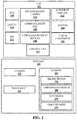
- FIG. 2 illustrates block diagrams of the UAV 102 and the payload 108, according to an embodiment of the present invention.
- the UAV 102 may include a power converter 202, a battery 204, an autopilot module 206, a power management module (PMM) 208, a communication unit 210, a Ground Facing Camera (GFC) 212, an Electronic Speed Controller (ESC) 214, a motor 216, a GPS 218 and a central unit 234.
- PMM power management module
- GFC Ground Facing Camera
- ESC Electronic Speed Controller
- the power converter 202 coupled to the ESC 214, is responsible for converting electric power received from the ground station 106 via the tether cable 108 to a power suited for functions and operational parameters of components of the UAV 102.
- the power converter 202 is a reconfigurable power converter capable of supplying varying level of powers to the UAV 102.
- the power converter 202 may be an AC-DC converter or a DC-DC converter.
- the power converter 202 may be reconfigured from the ground station 106 even during flight of the UAV 102 without requiring the UAV 102 to land at the ground station 106.
- the power converter 202 receives power for the UAV 102 and further supplies the power at varying levels.
- Power may be varied based on an operational status of the UAV 102.
- the operational status may be weight of payload 104, weight of the UAV 102, flight status that may include any other force being experienced by the UAV 102 like diverting force etc., and power status of the UAV 102.
- the battery 204 is an on-board battery at the UAV 102 to supply power to the UAV 102 in certain circumstances like disruption of power supply from the ground station, and the UAV entering an autopilot mode etc.
- the battery 204 may be a disposable or rechargeable battery of different chemistry types.
- the UAV 102 may further comprise a battery recharging circuit coupled to the tether cable 108 for recharging the battery while UAV 102 is powered by the ground power supply. Additionally, a supercapacitor may be used as the battery 204.
- the battery 202 may also be charged while the UAV 102 is powered by the ground power supply.
- the battery 204 may be attached on the UAV 102 using a mechanism which may be remotely controlled to detach/attach the battery 204 when required.
- the autopilot module 206 is responsible for putting the UAV 102 in autopilot mode under certain predetermined conditions.
- the UAV 102 may be put in the autopilot mode when there is disruption of power supply from the ground station 106.
- the PMM 208 is responsible for overall control and supply of power to the U A V 102.
- the PMM 208 also switches between the power converter 202 and battery 204 based on power requirements and prevailing conditions at the UAV 102.
- the communication unit 210 is responsible for performing wired/wireless communication with ground station and other flying objects.
- the GFC 212 is coupled to the auto-pilot module 206.
- the GFC 212 may be a day and night vision camera.
- the ESC 214 coupled to the central unit 234, and the motor 216 provides flying/hovering capability to the UAV.
- the GPS 218 provides GPS coordinates or location of the airborne UAV 102.
- the GPS coordinates may be provided to the ground station 106.
- the GPS may be substituted or replaced by any available global satellite navigation system or an inertial navigation system or an ego-motion base navigation system.
- the UAV 102 comprises the GPS 218 and the ground station 106 may include a GPS 334 ( FIG. 3 ).
- the payload 104 may include but not limited to a camera 220, a radio mast 222, and one or more sensors 224.
- the sensors 224 may include a smoke sensor 226, a temperature sensor 228, a GPS sensor 230 and (Chemical, Biological, Radiological, Nuclear) CBRN sensors 232.
- primary payload carrying capacity of the UAV 102 may be about 5 kilograms.
- the payload may be communicatively coupled to the ground station using the network 110 and may draw power from the UAV 102 or the tether cable 108.
- the tether cable 108 and electrical/electronic components of the UAV 102, and the payload 104 may be enclosed in a hardened case or coated with a protecting material to protect from CBRN attacks or other hostile environments.
- power level from the power converter 202 is determined. Power level is compared with a predetermined threshold power value. In case the power level is below the predetermined threshold, the UAV 202 switches to the auto pilot mode.
- the UAV 102 is powered by on board battery 204 and may be programmed to safely land on ground or a target position when the battery stamina goes below 5%.
- the UAV 102 starts a wireless communication its corresponding ground station. For example, the UAV 102 may be put in the autopilot mode when there is disruption of power supply from the ground station 106.
- the autopilot module 206 is coupled to the power management module 208.
- the autopilot module 206 receives an input, indicative of power status of the UAV, from the PMM 208 and in response switches to the battery 204for supplying power to the UAV 102.
- the GFC 212 is activated.
- the GFC 212 detects marks on the ground, such as infrared laser marks on the ground generates optical signals either in the visible or in non-visible regime corresponding to the detected marks.
- the optical signals are continually generated by maintaining the detected marks in the field-of-view of the GFC 212 during ascent or descent of the UAV.
- the marks are applied on a moving platform and the UAV 102 is instructed to follow the moving platform without any human assistance.
- the GFC 212 reports the optical signals to the auto-pilot module 206.
- the auto-pilot module 206 may then adjust the trajectory of the UAV 102 based on the optical signals. Such an arrangement of adjusting the trajectory based on the marks facilitates in maneuvering the UAV 102 to a target position in night or cloudy conditions when visibility of the ground is low.
- the ESC 214 may control or regulate the speed of the motor 214, during the autopilot mode, based on instructions from the ground station 106, the central unit 234, or pre-programmed instructions.
- the pre-programmed instructions may be saved in the central unit 234 and/or the autopilot module 206.
- the data from the GPS 334 is transmitted to the autopilot module 206.
- the autopilot module 206 is configured to adjust the trajectory of the UAV 102 so as to follow the ground station 106 which may be moving or stationary. Therefore, using this two GPS method, the UAV 102 may be made to follow the ground station 106 and monitor a targeted area even when the tether cable 108 is broken. The same principle can be used for safely landing the UAV on a target positon on grounds when the tether cable 108 is broken.
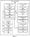
- FIG. 3 illustrates a block diagram of the ground station, according to an embodiment of the present invention.
- the ground station 106 may include a control unit 302 communicatively coupled to a power system 322, a tether system 312, an optical marker 328, a weigher 330, a transceiver 332, and a GPS 334.
- control unit 302 may include a processor 304 and a memory 306 communicatively coupled to the processor 304.
- the memory 306 may include data 308, and instructions 310.
- the control unit 302 manages overall functioning of the ground station 106 and control of the UAV 108.
- the control unit 302 sends and receives data or instructions to the tether system 312 and the power system 322. Further, the control unit 302 sends and receives data or instructions to the UAV 102 or other ground stations, via the transceiver 332.
- the ground station includes the optical marker 328 to create the marks.
- the marks may be captured by the GFC 212 of the UAV 102.
- the weigher 330 may determine weights of the UAV 102, a weight of a payload, a weight of the tether cable 108 released from the ground station 108.
- the GPS 334 may provide GPS coordinates of the ground station 106 to the UAV 102 or any other station or requesting device that is authorized. Further, the GPS 334 may coordinate with GPS 218 for implanting the two GPS method as described with reference to FIG. 2 .
- the tether system 312 may include the tether cable 108, a winch drum 318, and a tension meter 320.
- the tether cable 108 may include a power line 314 and a data line 316.
- the tether cable 108 may serve at least three functions. First, the tether cable 108 provides a mechanical restraint to the UAV 102 to keep the UAV 102 within predetermined spatial parameters during flight. Secondly, the tether cable may provide a continuous electric power from the ground station 106 to the UAV 102 via the power line 314.
- the tether cable 108 may include or support a wired communication link between the UAV 102 and the ground station 106 via the data line 316. Further, an optical fiber may also be incorporated in the tether cable 108 for providing a communication or an optical scope between the ground station 106 and the UAV 102. The optical scope may be used to capture images for variety of purposes while the UAV 102 is airborne.
- the tether cable 108 may be controlled using the winch drum 318 and the tension meter 320.
- the winch drum is an electric winch drum and releases or retracts the tether cable 108 based on a reading of the tension meter 320.
- the reading of the tension meter 320 may also be utilized by the control unit 302 to determine a diverting force acting on the UAV 102. Based on magnitude of the diverting force, the control unit 302 may supply a corresponding electric power to the UAV 102.
- the power system 322 may include a power source 324 and a power sensor 326.
- the power source 324 may be an alternating current or direct current power sources.
- the power source 324 may supply electrical power to the UAV 102. From the power source 324 power is transmitted via the tether cable 108 to the power converter 202 of the UAV 102.
- the power source 324 may include one of a generator, a battery bank, an AC power line, a household power source, a fuel cell, and a solar panel.
- the power converter 202 is a reconfigurable DC-DC convertor.
- the power converter 202 converts and conditions the power received from the power source 324 to a DC/AC power suitable for the proper functioning of the UAV 102. Thereafter, the DC/AC power may be routed via the power management module 208 to various components of the UAV 102 such as the battery 204, the autopilot module 206, the communication unit 210, the GFC 212, the ESC 214, the motor 216, and the GPS 218.
- the electrical power may also be supplied to the payload 104 if required.
- the ground station 106 may further include power converters for accepting any of the available power source(s) to produce a required operating power supply.
- the power system 322 may function as a universal power converter.
- the power system 322 may include a power conditioning module for condition in the power supply received from the power source 324.
- the power sensor 326 may be attached or coupled to the power source 324.
- the power sensor 324 may detect an energy level of the power source 324.
- the energy level of the power source 324 may be communicated to the control unit 302.
- the control unit 302 may communicate this information to the central unit 234 of the UAV 102 via transceiver 332, the tether cable 108, and the communication unit 210 of the UAV 102.
- the UAV 102 may be initiated into the autopilot mode where the power supply to the UAV 102 is provided by the battery 204.
- the battery 204 may supply power to the various components of the UAV 102. In yet another embodiment, the battery 204 may supply power to only mission critical components or to components required to maintain of the flight of UAV 102. If there is any malfunction in the tether cable 108 or the power cannot be supplied to the UAV 102 from the ground station 106, the power management module 208 puts the UAV 102 in autopilot mode. In the autopilot mode, the battery 204 acts as the primary power source and the communication between the UAV 102 and ground station 106 may be carried via a wireless link 110 instead of via the tether cable 108.
- the DC-DC power converter 202 is automatically switched off after a predetermined time interval and the UAV 102 is powered only by battery 204. By switching off the DC-DC power converter 202, the UAV 102 may hover for prolonged time period.
- FIG. 4 illustrates a schematic diagram of a plurality of UAVs 404, 408, and 412 coordinating with one another, according to an embodiment of the present invention.
- Each of the plurality of UAVs 404, 408, and 412 may be communicatively coupled to a corresponding ground station via a tether cable.
- UAVs 404, 408, and 412 may be communicatively coupled to a plurality of ground stations GS1 402, GS2 406, GSN 410 respectively via tether cables 108-1, 108-2, and 108-N.
- the plurality of UAVs 404, 408, and 412 may coordinate with one another to achieve a specific purpose or mission.
- the plurality of UAVs 404, 408, and 412 may coordinate to monitor a larger area under observation.
- one or more UAVs 404, 408, and 412 may be on standby and takes over from a malfunctioning UAV.
- the plurality of the UAVs 404, 408, and 412 may form a relay to transmit a message or data to long distances.
- an airborne network is formed between the pluralities of UAVs 404, 408, and 412 for exchanging or relaying data.
- the tether cables 108-1, 108-2, and 108-3 may be of different types or of same type.
- the plurality of the UAVs may carry same or different payloads.
- the UAVs form an aerial surveillance system.
- the system includes the plurality of UAVs 404, 408, and 412.
- Each UAV includes a communication unit 210-1, 210-2, 210-n (collectively referred to as 210).
- Each UAV shares surveillance data with other UAVs via the communication unit 210 using wireless communication via a network 414.
- the plurality of ground stations may be located at different geographical locations.
- Each UAV may be detachably coupled to one ground station via a tether cable.
- the tether cable is configured to supply a predetermined electric power to the UAV. The electric power may be determined based on weight of a payload being carried by the UAV.
- the tether cable is further configured to carry communication data between the UAV and the corresponding ground station.
- the predetermined electric power is supplied by an on board reconfigurable power converter.
- the plurality of UAVs forms a wireless network.
- the wireless network may be one of a star network, a mesh network, and a ring network.
- the network 414 may be any network including, but not limited to, an optical network, a cellular network, a satellite network, a Local Area Network (LAN), IEEE 802.XX network, Wide Area Network (WAN), SCSI, ATA, and the Internet or a combination thereof.
- LAN Local Area Network
- WAN Wide Area Network
- SCSI Serial Bus
- ATA Advanced Technology Attachment
- Internet the Internet or a combination thereof.
- FIG. 5 illustrates a schematic diagram of a plurality of UAVs 508, 510 and a plurality of ground stations 504, 506 coordinating with one another through a central processing station 502, according to an embodiment of the present invention.
- the plurality of ground stations 504, 506 and the plurality of UAVs 508, 510 are communicatively coupled to the central processing station 502 via a communication network 512.
- the central processing station 502 is configured to monitor the ground stations 504, 506 and the UAVs 508, 510 based on one or more predetermined parameters.
- the central processing station 502 is further configured to process data received from the ground stations 504, 506 and the UAVs 508, 510.
- the central processing station 502 is further configured to send commands and data to the ground stations and the UAVs.
- the plurality of ground stations 504, 506 are communicatively coupled to one another via the communication network 512.
- the communication network 512 may include a wired network, a wireless network, or a combination thereof.
- the ground stations 504 (GS1) - 506 (GSN) may be stationed in different geographical locations on earth such as in different states or countries. One or more of ground stations 504 (GS1) - 506 (GSN) may be located on land and other may be located on water. All ground stations 504 (GS1) - 506 (GSN) may be controlled via the CPS 410. In another embodiment, the ground stations 504 (GS1) - 506 (GSN) may utilize an internet/cloud service for inter station communications.
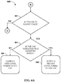
- FIG. 6A and FIG. 6B illustrate a method 600 for supplying an appropriate level of electrical power to the UAV 102 from the power source 324.
- the method begins at step 602 where it is determined whether the UAV 102 is in an ascent stage.
- step 610 the method 600 proceeds to step 610 ( FIG. 6B ). If the UAV 102 is in the ascent stage, it is further determined in step 604, whether the UAV 102 is subjected to a diverting force. If the UAV 102 is not subjected to the diverting force, the reconfigurable power converter 202 supplies a first level power to the UAV 102 in step 606. However, if the UAV 102 is subjected to a diverting force the reconfigurable power converter 202 supplies a second level power to the UAV 102 in step 608.
- step 610 it is determined whether the UAV 102 is hovering at a predetermined position.
- the method 600 proceeds to step 602 ( FIG. 6A ). If the UAV 102 is hovering at the predetermined position, it is further determined in step 612, whether the UAV 102 is subjected to a diverting force. If the UAV 102 is not subjected to the diverting force, the reconfigurable power converter 202 supplies a third level power to the UAV 102 in step 614. However, if the UAV 102 is subjected to a diverting force the reconfigurable power converter 202 supplies a fourth level power to the UAV 102 in step 616.
- the control unit 302 is configured to determine the first level power, the second level power, the third level power, and the fourth level power based on one or more of the weight of the UAV 102, a weight of a payload 104, a weight of the tether cable 108 released from the ground station 106, and the diverting force.
- the diverting force may include at least one of a gravitation force, a wind force, and a push or pull mechanical force by an object.
- FIG. 6C illustrates a method 650 for supplying requisite power to the UAV 102, according to an embodiment of the invention.
- the method 650 begins at step 652, wherein the information about operational status of the UAV 102 is received.
- the operational status may be either the payload weight being carried by the UAV, any disruption in power from the power source, UAV 102 in ascending status or descending status etc.
- the power level requirement of the UAV is identified.
- requisite power is provided to the UAV 102, identified in the previous step.
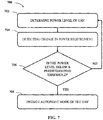
- FIG. 7 illustrates a method 700 for initiating an autopilot mode of the UAV 102, according to an embodiment of the present invention.
- the method 700 begins at step 702, wherein any power level change from the power source 324 is identified.
- FIG. 8 illustrates a method 800 for initiating an autopilot mode of the UAV 102 due to disruption power supply via the tether cable 108, according to an embodiment of the present invention.
- the method 800 begins at step 802, where in normal flight of the UAV 102, power is supplied to the UAV 102 from the power source 324 via the tether cable 108 and the reconfigurable power converter 202.
- the disruption may be due to ground power supply failure or breakage of the tether cable 108, breakage of only the power line 314 of the tether cable 108, or any other damage to the tether cable 108 or the power line 314.
- step 800 If there is no disruption in normal power supply, the method 800 returns to the step 802. If there is disruption in normal power supply then the method 800 proceeds to step 806, where the autopilot mode of the UAV 102 may be initiated. In the autopilot mode, in step 808, the power is supplied to the UAV 102 from the battery 204.
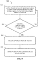
- FIG. 9 illustrates a method 900 for initiating an autopilot mode of the UAV 102 based on an energy level of the power source 324, according to an embodiment of the present invention.
- the method 800 begins at step 902, where in normal flight of the UAV 102, power is supplied to the UAV 102 from the power source 324 via the tether cable 108 and the reconfigurable power converter 202.
- step 904 it is determined whether the energy level of the power source 324 is below a predetermined threshold. If the energy level is not below the predetermined threshold, the method 900 returns to step 902. However, if energy level is below the predetermined threshold the method 900 proceeds to the step 906.
- the autopilot mode of the UAV 102 is initiated.
- the power is supplied to the UAV 102 from the battery 204.
- FIG. 10 illustrates a method 1000 for initiating an autopilot mode of the UAV 102 based on a temperature of the power converter 202, according to an embodiment of the present invention.
- the method 1000 begins at step 1002, where in normal flight of the UAV 102, power is supplied to the UAV 102 from the power source 324 via the tether cable 108 and the reconfigurable power converter 202.
- step 1004 it is determined whether the temperature of the power converter 202 is above a predetermined threshold. If the temperature is not above the predetermined threshold, the method 1000 returns to step 1002. However, if the temperature is above the predetermined threshold the method 1000 proceeds to the step 1006.
- the temperature sensor 228 monitors the temperature of the power converter 202 and reports to the central unit 234.
- step 1006 the autopilot mode of the UAV 108 is initiated.
- the central unit 234 commands the autopilot module 206 to put the UAV 102 in the autopilot mode.
- step 1008 the power is supplied to the UAV 108 from the battery 204 while the UAV 102 is in the autopilot mode. Thereafter, the battery 204 functions as the primary power source to the UAV 102. Subsequently, the power converter 202 may be switched-off for cooling down. In one embodiment, the battery 204 may function as the primary power source till the temperature of the power converter 202 comes within the predetermined temperature threshold.
- FIG. 11 illustrates a method 1100 for initiating wireless communication between the UAV 102 and the ground station 106, according to an embodiment of the present invention.
- the method 1100 begins at step 1102, wherein in normal operation of the UAV 102 the communication data between the UAV 102 and the ground station 106 is exchanged via the tether cable 108.
- step 1108 the communication data between the UAV 102 and the ground station 106 is exchanged via a wireless communication network.
- the control unit 302, the central unit 234, and the CPS 502 may be in form of computer processing unit having any and all features and capabilities of such processing units. Further, the present disclosure is applicable to all types of on- chip and off chip memories used in various in digital electronic circuitry, or in hardware, firmware, or in computer hardware, firmware, software, or in combination thereof.
- Apparatus of the invention can be implemented in a computer program product tangibly embodied in a machine-readable storage device for execution by a programmable processor; and methods actions can be performed by a programmable processor executing a program of instructions to perform functions of the invention by operating on input data and generating output.
- the invention can be implemented advantageously on a programmable system including at least one input device, and at least one output device.
- Each computer program can be implemented in a high-level procedural or object- oriented programming language or in assembly or machine language, if desired; and in any case, the language can be a compiled or interpreted language.
- Suitable processors include, by way of example, both general and specific microprocessors.
- a processor will receive instructions and data from a read-only memory and/or a random-access memory.
- a computer will include one or more mass storage devices for storing data file; such devices include magnetic disks and cards, such as internal hard disks, and removable disks and cards; magneto-optical disks; and optical disks.
- Storage devices suitable for tangibly embodying computer program instructions and data include all forms of volatile and non-volatile memory, including by way of example semiconductor memory devices, such as EPROM, EEPROM, and flash memory devices; magnetic disks such as internal hard disks and removable disks; magneto-optical disks; CD-ROM and DVD-ROM disks; and buffer circuits such as latches and/or flip flops. Any of the foregoing can be supplemented by, or incorporated in ASICs (application-specific integrated circuits), FPGAs (field-programmable gate arrays) and/or DSPs (digital signal processors).
- ASICs application-specific integrated circuits
- FPGAs field-programmable gate arrays
- DSPs digital signal processors
- the present subject matter provides an efficient system for powering a UAV 102.
- the power requirement of the UAV 102 depends on the operational status of the UAV 102, wherein the operational status may be either the payload weight being carried by the UAV, any disruption in power from the power source 324, UAV 102 in ascending status or descending status etc.
- the system determines power level requirement of the UAV 102 and efficiently provides suitable power to the UAV 102 for its flight. This mechanism therefore, makes sure that the UAV 102 has adequate power level through-out its flight.
- the present subject matter detects in case there is a drop in the power level from the power source 324 to the UAV 102.
- the UAV 102 may switch to an autopilot mode in order to land safely.
Applications Claiming Priority (1)
| Application Number | Priority Date | Filing Date | Title |
|---|---|---|---|
| IN201611028394 | 2016-08-20 |
Publications (2)
| Publication Number | Publication Date |
|---|---|
| EP3285130A2 true EP3285130A2 (de) | 2018-02-21 |
| EP3285130A3 EP3285130A3 (de) | 2018-04-18 |
Family
ID=59683439
Family Applications (1)
| Application Number | Title | Priority Date | Filing Date |
|---|---|---|---|
| EP17186886.2A Withdrawn EP3285130A3 (de) | 2016-08-20 | 2017-08-18 | Getethertes unbemanntes luftfahrzeug |
Country Status (2)
| Country | Link |
|---|---|
| US (1) | US10703474B2 (de) |
| EP (1) | EP3285130A3 (de) |
Cited By (3)
| Publication number | Priority date | Publication date | Assignee | Title |
|---|---|---|---|---|
| WO2021217459A1 (zh) * | 2020-04-28 | 2021-11-04 | 深圳市大疆创新科技有限公司 | 可移动平台的控制方法、可移动平台、控制终端及系统 |
| CN117228021A (zh) * | 2023-11-14 | 2023-12-15 | 贵州航天智慧农业有限公司 | 用于高粱害虫类别识别的无人机充放电调节方法及系统 |
| JP7444483B2 (ja) | 2022-04-19 | 2024-03-06 | 株式会社Tangent Japan | 無人飛行体システム |
Families Citing this family (20)
| Publication number | Priority date | Publication date | Assignee | Title |
|---|---|---|---|---|
| US11230391B2 (en) * | 2015-11-16 | 2022-01-25 | Altaeros Energies, Inc. | Systems and methods for attitude control of tethered aerostats |
| US11977395B2 (en) | 2016-03-24 | 2024-05-07 | Teledyne Flir Defense, Inc. | Persistent aerial communication and control system |
| EP3433692B1 (de) | 2016-03-24 | 2023-12-20 | Teledyne FLIR Detection, Inc. | System zur persistenten luftaufklärung und kommunikation |
| US10657485B2 (en) * | 2016-09-28 | 2020-05-19 | Federal Express Corporation | Paired drone-based systems and methods for conducting a modified inspection of a delivery vehicle |
| FR3066923B1 (fr) * | 2017-05-31 | 2021-01-01 | Elistair | Dispositif de protection pour la connexion entre un drone filaire detachable et son fil. |
| CN111279572A (zh) * | 2017-08-15 | 2020-06-12 | 萨罗尼科斯贸易与服务一人有限公司 | 为电动飞行器提供动力的组件和方法和/或配备所述组件的电动飞行器 |
| CN108365283A (zh) * | 2018-05-04 | 2018-08-03 | 深圳市道通智能航空技术有限公司 | 设备电池及无人机 |
| DE102018116439A1 (de) * | 2018-07-06 | 2020-01-09 | Dr. Ing. H.C. F. Porsche Aktiengesellschaft | System und Verfahren für ein aktives Thermomanagement |
| US11691761B2 (en) * | 2019-05-17 | 2023-07-04 | FlyFocus Sp. z.o.o. | Detachable power cable for unmanned aerial vehicle |
| US20220244127A1 (en) * | 2019-08-05 | 2022-08-04 | Seekops Inc. | Rapidly Deployable UAS System for Autonomous Inspection Operations Using a Combined Payload |
| GB2573915B (en) * | 2019-08-05 | 2020-07-08 | Drone Evolution Ltd | Universal aerial power supply system for a tethered small unmanned aerial vehicle |
| US11273911B2 (en) * | 2019-08-20 | 2022-03-15 | Textron Innovations Inc. | Detachable power tethering systems for aircraft |
| US11614430B2 (en) | 2019-12-19 | 2023-03-28 | Seekops Inc. | Concurrent in-situ measurement of wind speed and trace gases on mobile platforms for localization and qualification of emissions |
| CN111158400A (zh) * | 2020-01-19 | 2020-05-15 | 深圳市赛为智能股份有限公司 | 无人机飞控地面站系统及其工作方法 |
| US11417223B2 (en) | 2020-01-19 | 2022-08-16 | Flir Unmanned Aerial Systems Ulc | Flight altitude estimation systems and methods |
| US11423790B2 (en) | 2020-01-19 | 2022-08-23 | Flir Unmanned Aerial Systems Ulc | Tether management systems and methods |
| CN111776202B (zh) * | 2020-06-24 | 2022-02-08 | 南京航空航天大学 | 一种用于全向飞行物理交互平台的协作系统 |
| US11748866B2 (en) | 2020-07-17 | 2023-09-05 | Seekops Inc. | Systems and methods of automated detection of gas plumes using optical imaging |
| AU2021204693A1 (en) * | 2020-09-23 | 2022-04-07 | Insitu, Inc. (A Subsidiary Of The Boeing Company) | A controlled powerup sequence for an unmanned aerial vehicle (UAV) |
| CN112886831B (zh) * | 2021-01-15 | 2022-08-30 | 航天时代飞鸿技术有限公司 | 一种基于大功率系留无人机系统地面升压供配电系统 |
Family Cites Families (16)
| Publication number | Priority date | Publication date | Assignee | Title |
|---|---|---|---|---|
| US7631834B1 (en) * | 2006-02-24 | 2009-12-15 | Stealth Robotics, Llc | Aerial robot with dispensable conductive filament |
| US20110180667A1 (en) * | 2009-03-10 | 2011-07-28 | Honeywell International Inc. | Tether energy supply system |
| US8602349B2 (en) * | 2010-06-23 | 2013-12-10 | Dimitri Petrov | Airborne, tethered, remotely stabilized surveillance platform |
| US9800091B2 (en) * | 2011-06-09 | 2017-10-24 | Lasermotive, Inc. | Aerial platform powered via an optical transmission element |
| US20130233964A1 (en) * | 2012-03-07 | 2013-09-12 | Aurora Flight Sciences Corporation | Tethered aerial system for data gathering |
| US9045234B2 (en) * | 2013-04-04 | 2015-06-02 | Sunlight Photonics Inc. | Method for airborne kinetic energy conversion |
| US9310221B1 (en) * | 2014-05-12 | 2016-04-12 | Unmanned Innovation, Inc. | Distributed unmanned aerial vehicle architecture |
| JP6062079B2 (ja) * | 2014-05-30 | 2017-01-18 | エスゼット ディージェイアイ テクノロジー カンパニー リミテッドSz Dji Technology Co.,Ltd | 無人型航空輸送機(uav)の動作を制御するための制御器および方法ならびに乗り物 |
| US9678506B2 (en) * | 2014-06-19 | 2017-06-13 | Skydio, Inc. | Magic wand interface and other user interaction paradigms for a flying digital assistant |
| KR102253188B1 (ko) * | 2014-08-01 | 2021-05-18 | 엘지이노텍 주식회사 | 전기 자동차의 급속 충전 제어 장치 |
| US9511878B1 (en) * | 2014-08-13 | 2016-12-06 | Trace Live Network Inc. | System and method for adaptive y-axis power usage and non-linear battery usage for unmanned aerial vehicle equipped with action camera system |
| WO2016081041A1 (en) * | 2014-08-29 | 2016-05-26 | Reference Technologies Inc. | Muiti-propulsion design for unmanned aerial systems |
| US10195629B1 (en) * | 2014-09-12 | 2019-02-05 | Working Drones, Inc. | System, mobile base station and umbilical cabling and tethering (UCAT) apparatus |
| WO2016074182A1 (en) * | 2014-11-12 | 2016-05-19 | SZ DJI Technology Co., Ltd. | Method and system for recycling motor power of movable object |
| US9376208B1 (en) * | 2015-03-18 | 2016-06-28 | Amazon Technologies, Inc. | On-board redundant power system for unmanned aerial vehicles |
| US20170136887A1 (en) * | 2015-11-13 | 2017-05-18 | NextEv USA, Inc. | Electric vehicle aerial vehicle charging system and method of use |
-
2017
- 2017-08-18 EP EP17186886.2A patent/EP3285130A3/de not_active Withdrawn
- 2017-08-18 US US15/680,248 patent/US10703474B2/en active Active
Non-Patent Citations (1)
| Title |
|---|
| None |
Cited By (4)
| Publication number | Priority date | Publication date | Assignee | Title |
|---|---|---|---|---|
| WO2021217459A1 (zh) * | 2020-04-28 | 2021-11-04 | 深圳市大疆创新科技有限公司 | 可移动平台的控制方法、可移动平台、控制终端及系统 |
| JP7444483B2 (ja) | 2022-04-19 | 2024-03-06 | 株式会社Tangent Japan | 無人飛行体システム |
| CN117228021A (zh) * | 2023-11-14 | 2023-12-15 | 贵州航天智慧农业有限公司 | 用于高粱害虫类别识别的无人机充放电调节方法及系统 |
| CN117228021B (zh) * | 2023-11-14 | 2024-01-19 | 贵州航天智慧农业有限公司 | 用于高粱害虫类别识别的无人机充放电调节方法及系统 |
Also Published As
| Publication number | Publication date |
|---|---|
| US10703474B2 (en) | 2020-07-07 |
| EP3285130A3 (de) | 2018-04-18 |
| US20180050798A1 (en) | 2018-02-22 |
Similar Documents
| Publication | Publication Date | Title |
|---|---|---|
| US10703474B2 (en) | Tethered unmanned aerial vehicle | |
| JP6395835B2 (ja) | Uavのバッテリー電源バックアップシステムおよび方法 | |
| EP3433692B1 (de) | System zur persistenten luftaufklärung und kommunikation | |
| US9868526B2 (en) | Airborne drone delivery network and method of operating same | |
| JP6390022B2 (ja) | エネルギー提供ステーション | |
| US9778660B2 (en) | Unmanned aerial vehicle low-power operation | |
| US11359604B2 (en) | Method for reducing oscillations in wind turbine blades | |
| US20200189731A1 (en) | Cellular communication devices and methods | |
| WO2009153588A1 (en) | Compact unmanned aerial vehicle | |
| US20170225802A1 (en) | Systems and methods for deployment and operation of vertical take-off and landing (vtol) unmanned aerial vehicles | |
| WO2019083637A1 (en) | UAV GROUP LOAD BASED ON DEMAND FOR UAV SERVICE | |
| US10476296B1 (en) | Supplementing energy storage of an in-flight solar-powered UAV by casting light from a secondary in-flight UAV | |
| US20190100108A1 (en) | Robotic Vehicle Renewable Resource Charging Station Management Systems and Methods | |
| JP2018100088A (ja) | Uavにエネルギーを供給する方法、及びuav | |
| WO2018026754A1 (en) | Multi-craft uav carrier system and airframe | |
| JP2017528354A (ja) | Uavエネルギー交換ステーション | |
| WO2018089859A1 (en) | Cellular communication devices and methods | |
| KR101620557B1 (ko) | 수직이착륙 타워 장치 및 이를 이용한 무인 비행체의 비행 경로 설정 방법 | |
| US10843819B2 (en) | Recharging network for drones | |
| JP6791561B2 (ja) | Uavにエネルギーを供給する方法、及び装置 | |
| CN112041257B (zh) | 搬运风力涡轮机部件以便组装它们的系统和方法 | |
| KR20190102487A (ko) | 해양 등부표를 활용한 드론 격납 장치 및 방법 | |
| CA3050754A1 (en) | Air transportable fuel cell power system | |
| EP3956220B1 (de) | Uav-träger | |
| EP3810929A1 (de) | Verbesserungen im zusammenhang mit einer windturbinenwartung |
Legal Events
| Date | Code | Title | Description |
|---|---|---|---|
| PUAI | Public reference made under article 153(3) epc to a published international application that has entered the european phase |
Free format text: ORIGINAL CODE: 0009012 |
|
| AK | Designated contracting states |
Kind code of ref document: A2 Designated state(s): AL AT BE BG CH CY CZ DE DK EE ES FI FR GB GR HR HU IE IS IT LI LT LU LV MC MK MT NL NO PL PT RO RS SE SI SK SM TR |
|
| AX | Request for extension of the european patent |
Extension state: BA ME |
|
| PUAL | Search report despatched |
Free format text: ORIGINAL CODE: 0009013 |
|
| AK | Designated contracting states |
Kind code of ref document: A3 Designated state(s): AL AT BE BG CH CY CZ DE DK EE ES FI FR GB GR HR HU IE IS IT LI LT LU LV MC MK MT NL NO PL PT RO RS SE SI SK SM TR |
|
| AX | Request for extension of the european patent |
Extension state: BA ME |
|
| RIC1 | Information provided on ipc code assigned before grant |
Ipc: B64F 3/02 20060101ALI20180315BHEP Ipc: F41H 7/00 20060101ALI20180315BHEP Ipc: G05D 1/08 20060101AFI20180315BHEP Ipc: B64C 39/02 20060101ALI20180315BHEP Ipc: G05D 1/10 20060101ALI20180315BHEP |
|
| STAA | Information on the status of an ep patent application or granted ep patent |
Free format text: STATUS: THE APPLICATION IS DEEMED TO BE WITHDRAWN |
|
| 18D | Application deemed to be withdrawn |
Effective date: 20181019 |