EP3284909B1 - Dampfturbinenlaufschaufel und verfahren zur herstellung einer dampfturbinenlaufschaufel - Google Patents
Dampfturbinenlaufschaufel und verfahren zur herstellung einer dampfturbinenlaufschaufel Download PDFInfo
- Publication number
- EP3284909B1 EP3284909B1 EP16780005.1A EP16780005A EP3284909B1 EP 3284909 B1 EP3284909 B1 EP 3284909B1 EP 16780005 A EP16780005 A EP 16780005A EP 3284909 B1 EP3284909 B1 EP 3284909B1
- Authority
- EP
- European Patent Office
- Prior art keywords
- steam turbine
- turbine rotor
- rotor blade
- base material
- blade
- Prior art date
- Legal status (The legal status is an assumption and is not a legal conclusion. Google has not performed a legal analysis and makes no representation as to the accuracy of the status listed.)
- Active
Links
Images

Classifications
-
- F—MECHANICAL ENGINEERING; LIGHTING; HEATING; WEAPONS; BLASTING
- F01—MACHINES OR ENGINES IN GENERAL; ENGINE PLANTS IN GENERAL; STEAM ENGINES
- F01D—NON-POSITIVE DISPLACEMENT MACHINES OR ENGINES, e.g. STEAM TURBINES
- F01D5/00—Blades; Blade-carrying members; Heating, heat-insulating, cooling or antivibration means on the blades or the members
- F01D5/12—Blades
- F01D5/28—Selecting particular materials; Particular measures relating thereto; Measures against erosion or corrosion
-
- F—MECHANICAL ENGINEERING; LIGHTING; HEATING; WEAPONS; BLASTING
- F01—MACHINES OR ENGINES IN GENERAL; ENGINE PLANTS IN GENERAL; STEAM ENGINES
- F01D—NON-POSITIVE DISPLACEMENT MACHINES OR ENGINES, e.g. STEAM TURBINES
- F01D5/00—Blades; Blade-carrying members; Heating, heat-insulating, cooling or antivibration means on the blades or the members
- F01D5/12—Blades
- F01D5/28—Selecting particular materials; Particular measures relating thereto; Measures against erosion or corrosion
- F01D5/286—Particular treatment of blades, e.g. to increase durability or resistance against corrosion or erosion
-
- B—PERFORMING OPERATIONS; TRANSPORTING
- B23—MACHINE TOOLS; METAL-WORKING NOT OTHERWISE PROVIDED FOR
- B23K—SOLDERING OR UNSOLDERING; WELDING; CLADDING OR PLATING BY SOLDERING OR WELDING; CUTTING BY APPLYING HEAT LOCALLY, e.g. FLAME CUTTING; WORKING BY LASER BEAM
- B23K10/00—Welding or cutting by means of a plasma
- B23K10/02—Plasma welding
-
- B—PERFORMING OPERATIONS; TRANSPORTING
- B23—MACHINE TOOLS; METAL-WORKING NOT OTHERWISE PROVIDED FOR
- B23K—SOLDERING OR UNSOLDERING; WELDING; CLADDING OR PLATING BY SOLDERING OR WELDING; CUTTING BY APPLYING HEAT LOCALLY, e.g. FLAME CUTTING; WORKING BY LASER BEAM
- B23K10/00—Welding or cutting by means of a plasma
- B23K10/02—Plasma welding
- B23K10/027—Welding for purposes other than joining, e.g. build-up welding
-
- B—PERFORMING OPERATIONS; TRANSPORTING
- B23—MACHINE TOOLS; METAL-WORKING NOT OTHERWISE PROVIDED FOR
- B23K—SOLDERING OR UNSOLDERING; WELDING; CLADDING OR PLATING BY SOLDERING OR WELDING; CUTTING BY APPLYING HEAT LOCALLY, e.g. FLAME CUTTING; WORKING BY LASER BEAM
- B23K15/00—Electron-beam welding or cutting
-
- B—PERFORMING OPERATIONS; TRANSPORTING
- B23—MACHINE TOOLS; METAL-WORKING NOT OTHERWISE PROVIDED FOR
- B23K—SOLDERING OR UNSOLDERING; WELDING; CLADDING OR PLATING BY SOLDERING OR WELDING; CUTTING BY APPLYING HEAT LOCALLY, e.g. FLAME CUTTING; WORKING BY LASER BEAM
- B23K15/00—Electron-beam welding or cutting
- B23K15/0046—Welding
- B23K15/0093—Welding characterised by the properties of the materials to be welded
-
- B—PERFORMING OPERATIONS; TRANSPORTING
- B23—MACHINE TOOLS; METAL-WORKING NOT OTHERWISE PROVIDED FOR
- B23K—SOLDERING OR UNSOLDERING; WELDING; CLADDING OR PLATING BY SOLDERING OR WELDING; CUTTING BY APPLYING HEAT LOCALLY, e.g. FLAME CUTTING; WORKING BY LASER BEAM
- B23K26/00—Working by laser beam, e.g. welding, cutting or boring
- B23K26/20—Bonding
- B23K26/21—Bonding by welding
-
- B—PERFORMING OPERATIONS; TRANSPORTING
- B23—MACHINE TOOLS; METAL-WORKING NOT OTHERWISE PROVIDED FOR
- B23K—SOLDERING OR UNSOLDERING; WELDING; CLADDING OR PLATING BY SOLDERING OR WELDING; CUTTING BY APPLYING HEAT LOCALLY, e.g. FLAME CUTTING; WORKING BY LASER BEAM
- B23K26/00—Working by laser beam, e.g. welding, cutting or boring
- B23K26/34—Laser welding for purposes other than joining
- B23K26/342—Build-up welding
-
- B—PERFORMING OPERATIONS; TRANSPORTING
- B23—MACHINE TOOLS; METAL-WORKING NOT OTHERWISE PROVIDED FOR
- B23K—SOLDERING OR UNSOLDERING; WELDING; CLADDING OR PLATING BY SOLDERING OR WELDING; CUTTING BY APPLYING HEAT LOCALLY, e.g. FLAME CUTTING; WORKING BY LASER BEAM
- B23K31/00—Processes relevant to this subclass, specially adapted for particular articles or purposes, but not covered by any single one of main groups B23K1/00 - B23K28/00
-
- B—PERFORMING OPERATIONS; TRANSPORTING
- B23—MACHINE TOOLS; METAL-WORKING NOT OTHERWISE PROVIDED FOR
- B23K—SOLDERING OR UNSOLDERING; WELDING; CLADDING OR PLATING BY SOLDERING OR WELDING; CUTTING BY APPLYING HEAT LOCALLY, e.g. FLAME CUTTING; WORKING BY LASER BEAM
- B23K31/00—Processes relevant to this subclass, specially adapted for particular articles or purposes, but not covered by any single one of main groups B23K1/00 - B23K28/00
- B23K31/02—Processes relevant to this subclass, specially adapted for particular articles or purposes, but not covered by any single one of main groups B23K1/00 - B23K28/00 relating to soldering or welding
-
- B—PERFORMING OPERATIONS; TRANSPORTING
- B23—MACHINE TOOLS; METAL-WORKING NOT OTHERWISE PROVIDED FOR
- B23K—SOLDERING OR UNSOLDERING; WELDING; CLADDING OR PLATING BY SOLDERING OR WELDING; CUTTING BY APPLYING HEAT LOCALLY, e.g. FLAME CUTTING; WORKING BY LASER BEAM
- B23K35/00—Rods, electrodes, materials, or media, for use in soldering, welding, or cutting
- B23K35/22—Rods, electrodes, materials, or media, for use in soldering, welding, or cutting characterised by the composition or nature of the material
- B23K35/24—Selection of soldering or welding materials proper
- B23K35/32—Selection of soldering or welding materials proper with the principal constituent melting at more than 1550°C
- B23K35/325—Ti as the principal constituent
-
- B—PERFORMING OPERATIONS; TRANSPORTING
- B23—MACHINE TOOLS; METAL-WORKING NOT OTHERWISE PROVIDED FOR
- B23K—SOLDERING OR UNSOLDERING; WELDING; CLADDING OR PLATING BY SOLDERING OR WELDING; CUTTING BY APPLYING HEAT LOCALLY, e.g. FLAME CUTTING; WORKING BY LASER BEAM
- B23K35/00—Rods, electrodes, materials, or media, for use in soldering, welding, or cutting
- B23K35/22—Rods, electrodes, materials, or media, for use in soldering, welding, or cutting characterised by the composition or nature of the material
- B23K35/24—Selection of soldering or welding materials proper
- B23K35/32—Selection of soldering or welding materials proper with the principal constituent melting at more than 1550°C
- B23K35/327—Selection of soldering or welding materials proper with the principal constituent melting at more than 1550°C comprising refractory compounds, e.g. carbides
-
- C—CHEMISTRY; METALLURGY
- C22—METALLURGY; FERROUS OR NON-FERROUS ALLOYS; TREATMENT OF ALLOYS OR NON-FERROUS METALS
- C22C—ALLOYS
- C22C1/00—Making non-ferrous alloys
- C22C1/02—Making non-ferrous alloys by melting
-
- C—CHEMISTRY; METALLURGY
- C22—METALLURGY; FERROUS OR NON-FERROUS ALLOYS; TREATMENT OF ALLOYS OR NON-FERROUS METALS
- C22C—ALLOYS
- C22C14/00—Alloys based on titanium
-
- C—CHEMISTRY; METALLURGY
- C22—METALLURGY; FERROUS OR NON-FERROUS ALLOYS; TREATMENT OF ALLOYS OR NON-FERROUS METALS
- C22F—CHANGING THE PHYSICAL STRUCTURE OF NON-FERROUS METALS AND NON-FERROUS ALLOYS
- C22F1/00—Changing the physical structure of non-ferrous metals or alloys by heat treatment or by hot or cold working
- C22F1/02—Changing the physical structure of non-ferrous metals or alloys by heat treatment or by hot or cold working in inert or controlled atmosphere or vacuum
-
- C—CHEMISTRY; METALLURGY
- C22—METALLURGY; FERROUS OR NON-FERROUS ALLOYS; TREATMENT OF ALLOYS OR NON-FERROUS METALS
- C22F—CHANGING THE PHYSICAL STRUCTURE OF NON-FERROUS METALS AND NON-FERROUS ALLOYS
- C22F1/00—Changing the physical structure of non-ferrous metals or alloys by heat treatment or by hot or cold working
- C22F1/16—Changing the physical structure of non-ferrous metals or alloys by heat treatment or by hot or cold working of other metals or alloys based thereon
- C22F1/18—High-melting or refractory metals or alloys based thereon
-
- C—CHEMISTRY; METALLURGY
- C22—METALLURGY; FERROUS OR NON-FERROUS ALLOYS; TREATMENT OF ALLOYS OR NON-FERROUS METALS
- C22F—CHANGING THE PHYSICAL STRUCTURE OF NON-FERROUS METALS AND NON-FERROUS ALLOYS
- C22F1/00—Changing the physical structure of non-ferrous metals or alloys by heat treatment or by hot or cold working
- C22F1/16—Changing the physical structure of non-ferrous metals or alloys by heat treatment or by hot or cold working of other metals or alloys based thereon
- C22F1/18—High-melting or refractory metals or alloys based thereon
- C22F1/183—High-melting or refractory metals or alloys based thereon of titanium or alloys based thereon
-
- F—MECHANICAL ENGINEERING; LIGHTING; HEATING; WEAPONS; BLASTING
- F01—MACHINES OR ENGINES IN GENERAL; ENGINE PLANTS IN GENERAL; STEAM ENGINES
- F01D—NON-POSITIVE DISPLACEMENT MACHINES OR ENGINES, e.g. STEAM TURBINES
- F01D25/00—Component parts, details, or accessories, not provided for in, or of interest apart from, other groups
-
- F—MECHANICAL ENGINEERING; LIGHTING; HEATING; WEAPONS; BLASTING
- F01—MACHINES OR ENGINES IN GENERAL; ENGINE PLANTS IN GENERAL; STEAM ENGINES
- F01D—NON-POSITIVE DISPLACEMENT MACHINES OR ENGINES, e.g. STEAM TURBINES
- F01D5/00—Blades; Blade-carrying members; Heating, heat-insulating, cooling or antivibration means on the blades or the members
- F01D5/12—Blades
- F01D5/14—Form or construction
- F01D5/147—Construction, i.e. structural features, e.g. of weight-saving hollow blades
-
- B—PERFORMING OPERATIONS; TRANSPORTING
- B23—MACHINE TOOLS; METAL-WORKING NOT OTHERWISE PROVIDED FOR
- B23K—SOLDERING OR UNSOLDERING; WELDING; CLADDING OR PLATING BY SOLDERING OR WELDING; CUTTING BY APPLYING HEAT LOCALLY, e.g. FLAME CUTTING; WORKING BY LASER BEAM
- B23K2101/00—Articles made by soldering, welding or cutting
- B23K2101/001—Turbines
-
- B—PERFORMING OPERATIONS; TRANSPORTING
- B23—MACHINE TOOLS; METAL-WORKING NOT OTHERWISE PROVIDED FOR
- B23K—SOLDERING OR UNSOLDERING; WELDING; CLADDING OR PLATING BY SOLDERING OR WELDING; CUTTING BY APPLYING HEAT LOCALLY, e.g. FLAME CUTTING; WORKING BY LASER BEAM
- B23K2103/00—Materials to be soldered, welded or cut
- B23K2103/08—Non-ferrous metals or alloys
- B23K2103/14—Titanium or alloys thereof
-
- C—CHEMISTRY; METALLURGY
- C22—METALLURGY; FERROUS OR NON-FERROUS ALLOYS; TREATMENT OF ALLOYS OR NON-FERROUS METALS
- C22F—CHANGING THE PHYSICAL STRUCTURE OF NON-FERROUS METALS AND NON-FERROUS ALLOYS
- C22F1/00—Changing the physical structure of non-ferrous metals or alloys by heat treatment or by hot or cold working
-
- F—MECHANICAL ENGINEERING; LIGHTING; HEATING; WEAPONS; BLASTING
- F05—INDEXING SCHEMES RELATING TO ENGINES OR PUMPS IN VARIOUS SUBCLASSES OF CLASSES F01-F04
- F05D—INDEXING SCHEME FOR ASPECTS RELATING TO NON-POSITIVE-DISPLACEMENT MACHINES OR ENGINES, GAS-TURBINES OR JET-PROPULSION PLANTS
- F05D2220/00—Application
- F05D2220/30—Application in turbines
- F05D2220/31—Application in turbines in steam turbines
-
- F—MECHANICAL ENGINEERING; LIGHTING; HEATING; WEAPONS; BLASTING
- F05—INDEXING SCHEMES RELATING TO ENGINES OR PUMPS IN VARIOUS SUBCLASSES OF CLASSES F01-F04
- F05D—INDEXING SCHEME FOR ASPECTS RELATING TO NON-POSITIVE-DISPLACEMENT MACHINES OR ENGINES, GAS-TURBINES OR JET-PROPULSION PLANTS
- F05D2230/00—Manufacture
- F05D2230/30—Manufacture with deposition of material
- F05D2230/31—Layer deposition
-
- F—MECHANICAL ENGINEERING; LIGHTING; HEATING; WEAPONS; BLASTING
- F05—INDEXING SCHEMES RELATING TO ENGINES OR PUMPS IN VARIOUS SUBCLASSES OF CLASSES F01-F04
- F05D—INDEXING SCHEME FOR ASPECTS RELATING TO NON-POSITIVE-DISPLACEMENT MACHINES OR ENGINES, GAS-TURBINES OR JET-PROPULSION PLANTS
- F05D2240/00—Components
- F05D2240/20—Rotors
- F05D2240/30—Characteristics of rotor blades, i.e. of any element transforming dynamic fluid energy to or from rotational energy and being attached to a rotor
- F05D2240/307—Characteristics of rotor blades, i.e. of any element transforming dynamic fluid energy to or from rotational energy and being attached to a rotor related to the tip of a rotor blade
-
- F—MECHANICAL ENGINEERING; LIGHTING; HEATING; WEAPONS; BLASTING
- F05—INDEXING SCHEMES RELATING TO ENGINES OR PUMPS IN VARIOUS SUBCLASSES OF CLASSES F01-F04
- F05D—INDEXING SCHEME FOR ASPECTS RELATING TO NON-POSITIVE-DISPLACEMENT MACHINES OR ENGINES, GAS-TURBINES OR JET-PROPULSION PLANTS
- F05D2300/00—Materials; Properties thereof
- F05D2300/10—Metals, alloys or intermetallic compounds
- F05D2300/17—Alloys
- F05D2300/174—Titanium alloys, e.g. TiAl
-
- F—MECHANICAL ENGINEERING; LIGHTING; HEATING; WEAPONS; BLASTING
- F05—INDEXING SCHEMES RELATING TO ENGINES OR PUMPS IN VARIOUS SUBCLASSES OF CLASSES F01-F04
- F05D—INDEXING SCHEME FOR ASPECTS RELATING TO NON-POSITIVE-DISPLACEMENT MACHINES OR ENGINES, GAS-TURBINES OR JET-PROPULSION PLANTS
- F05D2300/00—Materials; Properties thereof
- F05D2300/20—Oxide or non-oxide ceramics
- F05D2300/22—Non-oxide ceramics
- F05D2300/226—Carbides
- F05D2300/2262—Carbides of titanium, e.g. TiC
Definitions
- the present invention relates to a steam turbine rotor blade and a method for manufacturing a steam turbine rotor blade.
- the improvement of efficiency (for example, the improvement of efficiency of steam turbines) of thermal power generation plants has been desired.
- One of the effective means for improving the efficiency of steam turbines is to increase the length of a steam turbine long blade (rotor blade) .
- the steam turbine long blade has a problem of abrasion (erosion) of a tip portion by collision with water droplets. Erosion becomes severe because the peripheral speed of the tip portion increases as the length of the steam turbine long blade is increased.
- a titanium-based alloy and an iron and steel material are used for the steam turbine long blade.
- a titanium-based material has a lower specific gravity than that of an iron and steel material, and therefore is a material suitable for increasing the length of the steam turbine long blade.
- a forged plate having excellent abrasion resistance called "erosion shield” is bonded to a blade tip portion.
- an erosion shield material for a titanium-based long blade a long blade using a titanium-based material
- a titanium-based material is used for adapting the thermal expansion coefficient, however, the titanium-based material has lower abrasion resistance than the iron and steel material, and therefore, it is difficult to further increase the length of the blade.
- an erosion shield having excellent abrasion resistance for use in a titanium-based long blade has been demanded.
- a shielding method there is a method for forming a hard ceramic coating film by vapor deposition or the like on a blade tip portion (see, for example, PTL 1).
- PTL 2 discloses a surface treatment method for a steam turbine rotor blade, characterized in that a blade tip leading edge portion of a steam turbine low-pressure last stage blade composed of a titanium alloy is finished into a predetermined shape by machining, and thereafter, the surface of a base material is melted by a high-energy density source, and a ceramic powder is dispersed and overlay-welded in the base material.
- PTL 3 discloses a method for manufacturing a corrosion resistant alloy, characterized in that a mixture composed of a ceramic powder at a volume ratio of 20 to 60% and the remainder substantially consisting of titanium or a titanium alloy powder is prepared, and thereafter, this mixture is fired in vacuum or in an inert gas, and molded by a hot isostatic pressing process.
- the erosion shield formed by vapor deposition described in the above PTL 1 has a film thickness of several tens of micrometers and is extremely thin, and therefore, sufficient reliability may not be obtained. Further, also in the technique described in PTL 2, the thickness of the hard coating film is not sufficient, and therefore, a sufficient strength and reliability may not be obtained, either. Still further, even in the technique described in PTL 3, the strength may be not sufficient. That is, the conventional erosion shields did not sufficiently achieve both abrasion resistance and reliability.
- the invention provides a steam turbine rotor blade achieving both abrasion resistance and reliability, and a method for manufacturing a steam turbine rotor blade capable of obtaining such a steam turbine rotor blade.
- a steam turbine rotor blade achieving both abrasion resistance and reliability, and a method for manufacturing a steam turbine rotor blade capable of obtaining such a steam turbine rotor blade can be provided.
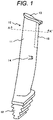
- FIG. 1 is a schematic view showing one example of a steam turbine rotor blade according to the invention.
- a steam turbine rotor blade 10 according to the invention includes a blade base material 11 composed of a titanium alloy, and an erosion shield 15 formed on a surface of the blade base material 11.
- the erosion shield 15 is formed at a tip of the blade base material 11 where the peripheral speed is high and abrasion further increases.
- the blade base material 11 includes a stub 14 for integrating the adjacent blade by torsion, and a continuous cover 13.
- This steam turbine rotor blade 10 is an axial entry type having a blade root portion 12 with an inverted Christmas tree shape.
- FIG. 2A is a view schematically showing one example of a cross section taken along the line A-A' of the blade base material and the erosion shield in FIG. 1
- FIG. 2B is a view schematically showing another example of a cross section taken along the line A-A' of the blade base material and the erosion shield in FIG. 1
- the erosion shield 15 according to the invention is formed of a weld overlay layer (hereinafter also referred to as "overlay layer”) (hereinafter the reference numeral 15 also refers to "weld overlay layer”) .
- the weld overlay layer 15 may be formed from a side edge to a wide surface of the blade base material 11 as shown in FIG.
- This weld overlay layer 15 is characterized by including a parent phase composed of pure titanium in which a metal element being chromium is solid-dissolved or a titanium alloy in which a metal element being chromium is solid-dissolved, and a hard phase of titanium silicide dispersed in the parent phase.
- a parent phase composed of pure titanium in which a metal element being chromium is solid-dissolved or a titanium alloy in which a metal element being chromium is solid-dissolved
- a hard phase of titanium silicide dispersed in the parent phase will be described in detail.
- the parent phase (matrix) constituting the weld overlay layer 15 is formed from the same material as that of the blade base material 11, that is, a material in which a metal element is solid-dissolved in pure titanium or a titanium alloy.
- a titanium alloy for example, 6Al-4V-Ti or 15Mo-5Zr-3Al-Ti can be used.
- a metal element being chromium is solid-dissolved in the above-mentioned parent phase.
- the parent phase is hardened so as to improve the hardness of the weld overlay layer 15, and therefore, the abrasion resistance can be improved.
- This metal element is derived from inorganic compound particles as described in the below-mentioned manufacturing method. It is necessary that the metal element should be a material which is solid-dissolved in the parent phase to harden the parent phase, like chromium (Cr), iron (Fe), and the like. However, in the present invention chromium is used.
- the weld overlay layer 15 includes a hard phase being titanium silicide dispersed in the parent phase.
- a hard phase being titanium silicide dispersed in the parent phase.
- This hard phase is a phase produced by reacting part of the parent phase with a material derived from inorganic compound particles as described in the below-mentioned manufacturing method. Incidentally, this hard phase can be analyzed by XRD measurement of the weld overlay layer 15.
- the erosion shield 15 according to the invention is a weld overlay layer including the above-mentioned parent phase and hard phase, and has a melted and solidified structure, and therefore is clearly different from the structure of the hard film formed by vapor deposition in the above-mentioned PTL 1.
- the thickness of the weld overlay layer of the invention is not particularly limited, however, a weld overlay layer having a thickness of 20 mm or more can be formed, and is thicker than the hard film having a film thickness of several tens of micrometers described in PTL 1, and therefore, the reliability of the steam turbine rotor blade can be enhanced.
- the surface of the blade base material is melted, and a ceramic powder is fed to the melted region, whereby the weld overlay layer is formed.
- the feeding amount of the ceramic powder is increased, the ceramic powder is not diffused in the base material, and therefore, the composition of the weld overlay layer to be obtained is the same as the composition of the ceramic powder, and thus, a weld overlay layer having a structure in which a hard phase derived from inorganic compound particles is dispersed in a parent phase composed of pure titanium in which a metal element is solid-dissolved or a titanium alloy in which a metal element is solid-dissolved as in the invention is not formed.
- the steam turbine rotor blade according to the invention includes the erosion shield having both excellent abrasion resistance and excellent reliability.
- the application place of the steam turbine rotor blade is of course not limited, but is preferably a last stage of a steam turbine where the humidity is highest, and in such a case, the effect of the invention can be exhibited most strongly.
- the method for manufacturing a steam turbine rotor blade according to the invention includes a step of forming an erosion shield on a blade base material 11, and this step of forming the erosion shield includes a step of forming a weld overlay layer by melting a welding raw material powder containing a raw material powder of parent phase particles and a raw material powder of inorganic compound particles being chromium silicide by a heat source on the blade base material 11.
- a mixed powder (welding raw material powder) obtained by mixing a raw material powder of parent phase particles (parent powder) constituting the above-mentioned parent phase with inorganic compound particles is prepared.
- the above-mentioned mixed powder is melted by a heat source on the blade base material 11 to form an overlay layer.
- the type of the heat source is not particularly limited, but examples thereof include a laser, a plasma transfer arc, and an electron beam.
- the inorganic compound particles inorganic compound particles in which some are solid-dissolved in the parent phase, and some react with the parent phase to form a hard phase are used.
- the inorganic compound particles consist of chromium silicide.
- a metal element (chromium) constituting the inorganic compound particles is solid-dissolved in the parent phase in the process of melting to harden the parent phase.
- an element (silicon) other than the metal element to be solid-dissolved in the parent phase of the inorganic compound particles reacts with part of the parent phase to form a hard phase.
- the content of the inorganic compound particles in the raw material powder is from 5 to 15 vol%.
- the content is less than 5 vol%, an effect of hardening the parent phase is not sufficiently obtained. Further, when the content is more than 15 vol%, the hardening of the parent phase excessively proceeds to generate a crack when welding.
- a step of forming a welding shield groove portion in a portion of the blade base material 11 where the erosion shield 15 is formed, a step of annealing the weld overlay layer 15, and a step of machining the weld overlay layer 15 into a final shape may be included.
- the annealing is preferably performed in vacuum by setting the retention temperature to 450°C to 550°C (450°C or higher and 550°C or lower) and the retention time to 8 to 10 hours. By selecting a heat source whose heat input is small, annealing to remove residual stress can be omitted.
- the method for manufacturing a steam turbine rotor blade according to the invention is characterized by using a mixed powder obtained by mixing a parent powder with an inorganic compound powder so as to obtain the structure of the weld overlay layer described above.
- the metal element in the inorganic compound particles is solid-dissolved in the parent phase to harden the parent phase, and further, due to a hard phase produced by reacting the parent phase with the inorganic compound particles, the hardness of the weld overlay layer can be further improved.
- test pieces (Inventive Material No. 4 and Comparative Materials Nos. 1 to 3 and 5 to 11) subjected to an element test will be described.
- a 6Al-4V-Ti alloy was prepared, and as the base material of No. 11, a 15Mo-5Zr-3Al-Ti alloy forged plate was prepared.
- No. 1 to 10 As the base material of Nos. 1 to 10, a 6Al-4V-Ti alloy was prepared, and as the base material of No. 11, a 15Mo-5Zr-3Al-Ti alloy forged plate was prepared. With respect to No.
- a parent powder titanium-based powder which is the raw material powder of the parent phase particles and an inorganic compound powder which is the raw material powder of the inorganic compound particles are fed from different powder pods to a welding portion of the base material to give a predetermined mixing ratio, and melted on the surface of the base material by a laser, whereby a weld overlay layer was formed.
- the composition of the welding material and the composition of the hard phase are shown in the following Table 1. Incidentally, the descriptions in the parentheses in the column of "Inorganic compound powder" each denote the content of the inorganic compound powder in the raw material powder.
- No. 4 is an Example according to the invention, and Nos. 1 to 3 and 5 to 11 are Comparative Examples . From the results shown in Table 1, Examples Nos. 1 to 7 all have an excellent hardness and excellent abrasion resistance.
- Examples Nos. 1 to 7 all have an excellent hardness and excellent abrasion resistance.
- the metal element is solid-dissolved in the parent phase, and the hard phase is formed and dispersed in the parent phase.
- the evaluation results of the respective test pieces will be described in detail.
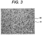
- FIG. 3 is a light micrograph of the weld overlay layer of Example (No. 2). As shown in FIG. 3 , it is clearly found that a hard phase (black portion) 31 is deposited and dispersed in a parent phase 30 (gray portion).
- the amount of thinning of the inventive material was smaller than that of the comparative material, and therefore, improvement of the abrasion resistance was confirmed.
- No. 9 which is a comparative material, a crack was generated in the overlay layer, and therefore, the abrasion resistance could not be evaluated.
- the inorganic compound powder did not contain an element which reacts with the parent phase to form a hard phase, and the abrasion resistance was not improved.
- a reference example in which the steam turbine rotor blade not according to the invention was used in an actual machine will be described.
- a 40-inch steam turbine titanium long blade composed of a 6Al-4V-Ti alloy was fabricated.
- closed-die forging was performed for a 6Al-4V-Ti alloy billet using a 40-inch blade die.
- a heat treatment for adjusting the microstructure was performed.
- the entire blade was machined into a predetermined shape, and a shield welding groove portion was provided in a tip portion.
- the raw material shown in No. 2 in Table 1 was melted by a laser, and overlay welding was performed.
- processing of the overlay layer, or surface polishing or bend straightening of the entire blade was performed, whereby a 40-inch long blade was formed.
Landscapes
- Engineering & Computer Science (AREA)
- Mechanical Engineering (AREA)
- Chemical & Material Sciences (AREA)
- Physics & Mathematics (AREA)
- Materials Engineering (AREA)
- Organic Chemistry (AREA)
- Metallurgy (AREA)
- Optics & Photonics (AREA)
- Plasma & Fusion (AREA)
- Thermal Sciences (AREA)
- Crystallography & Structural Chemistry (AREA)
- General Engineering & Computer Science (AREA)
- Architecture (AREA)
- Turbine Rotor Nozzle Sealing (AREA)
- Welding Or Cutting Using Electron Beams (AREA)
- Laser Beam Processing (AREA)
Claims (9)
- Verfahren zur Herstellung einer Dampfturbinenrotorschaufel, das ein Verfahren zur Herstellung einer Dampfturbinenrotorschaufel mit einem aus einer Titanlegierung zusammengesetzten Schaufelbasismaterial (11) und einem auf einer Oberfläche des Schaufelbasismaterials ausgebildeten Erosionsschild (15) ist, wobeidas Verfahren einen Schritt umfasst, bei dem das Erosionsschild auf einer Oberfläche des Schaufelbasismaterials ausgebildet wird,wobei der Schritt des Ausbildens des Erosionsschildes einen Schritt enthält, bei dem eine Schweißüberzugsschicht durch Schmelzen eines Schweißrohmaterialpulvers, das durch Mischen eines Rohmaterialpulvers von aus reinem Titan oder einer Titanlegierung zusammengesetzten Elternphasenpartikeln und eines Rohmaterialpulvers von Partikeln einer anorganischen Verbindung erhalten wird, mittels einer Wärmequelle auf dem Schaufelbasismaterial ausgebildet wird, so dass einige der Elternphasenpartikel mit den Partikeln der anorganischen Verbindung reagieren und eine harte Phase bilden und wobei die harte Phase sich in der Elternphase verteilt, wobei ein Metallelement in der Elternphase fest-aufgelöst wird, undwobei Chromsilizid als die Partikel der anorganischen Verbindung verwendet wird, wobei die harte Phase aus Titansilizid zusammengesetzt ist, das Metallelement Chrom ist und der Anteil der Partikel der anorganischen Verbindung im Schweißrohmaterialpulver von 5 bis 15 Vol-% rangiert.
- Verfahren zum Herstellen einer Dampfturbinenrotorschaufel nach Anspruch 1, ferner umfassend einen Schritt, bei dem ein Schweißschild-Nutabschnitt in einem Abschnitt des Schaufelbasismaterials (11), in dem das Erosionsschild (15) ausgebildet ist, ausgebildet wird, einen Schritt, bei dem die Schweißüberzugsschicht gekühlt wird, und/oder einen Schritt, bei dem die Schweißüberzugsschicht maschinell bearbeitet wird.
- Verfahren zum Herstellen einer Dampfturbinenrotorschaufel nach Anspruch 1 oder 2, wobei als die Wärmequelle ein Laser, ein Plasmatransferbogen oder ein Elektronenstrahl verwendet wird.
- Verfahren zum Herstellen einer Dampfturbinenrotorschaufel nach einem der Ansprüche 1 bis 3, wobei das Erosionsschild (15) eine Dicke von 20 mm oder mehr aufweist und/oder das Erosionsschild in einem Spitzenabschnitt der Dampfturbinenrotorschaufel vorgesehen ist.
- Verfahren zum Herstellen einer Dampfturbinenrotorschaufel nach einem der Ansprüche 1 bis 4, wobei die Titanlegierung 6Al-4V-Ti oder 15Mo-5Zr-3Al-Ti ist.
- Dampfturbinenrotorschaufel, die durch das Herstellungsverfahren nach einem der Ansprüche 1 bis 5 erhalten werden kann, umfassend das Schaufelbasismaterial (11) und das auf der Oberfläche des Schaufelbasismaterials ausgebildete Erosionsschild (15), wobei:das Schaufelbasismaterial aus einer Titanlegierung zusammengesetzt ist,das Erosionsschild aus der Schweißüberzugsschicht, die die Elternphase enthält, die aus reinem Titan, in dem Chrom fest-aufgelöst ist, oder aus der Titanlegierung, in der Chrom fest-aufgelöst ist, zusammengesetzt ist, und die in der Elternphase verteilte harte Phase enthält; unddie harte Phase aus Titansilizid zusammengesetzt ist.
- Dampfturbinenrotorschaufel nach Anspruch 6, wobei das Erosionsschild (15) eine Dicke von 20 mm oder mehr aufweist und/oder das Erosionsschild in einem Spitzenabschnitt der Dampfturbinenrotorschaufel vorgesehen ist.
- Dampfturbinenrotorschaufel nach Anspruch 6 oder 7, wobei die Titanlegierung 6Al-4V-Ti oder 15Mo-5Zr-3Al-Ti ist.
- Dampfturbinenrotorschaufel nach einem der Ansprüche 6 bis 8, wobei die Dampfturbinenrotorschaufel eine lange Schaufel ist, die für eine letzte Stufe einer Dampfturbine zu verwenden ist.
Applications Claiming Priority (2)
| Application Number | Priority Date | Filing Date | Title |
|---|---|---|---|
| JP2015084960 | 2015-04-17 | ||
| PCT/JP2016/061677 WO2016167214A1 (ja) | 2015-04-17 | 2016-04-11 | 蒸気タービン動翼及び蒸気タービン動翼の製造方法 |
Publications (3)
| Publication Number | Publication Date |
|---|---|
| EP3284909A1 EP3284909A1 (de) | 2018-02-21 |
| EP3284909A4 EP3284909A4 (de) | 2018-11-14 |
| EP3284909B1 true EP3284909B1 (de) | 2022-05-11 |
Family
ID=57126463
Family Applications (1)
| Application Number | Title | Priority Date | Filing Date |
|---|---|---|---|
| EP16780005.1A Active EP3284909B1 (de) | 2015-04-17 | 2016-04-11 | Dampfturbinenlaufschaufel und verfahren zur herstellung einer dampfturbinenlaufschaufel |
Country Status (6)
| Country | Link |
|---|---|
| US (1) | US10378366B2 (de) |
| EP (1) | EP3284909B1 (de) |
| JP (1) | JP6301554B2 (de) |
| KR (1) | KR102002239B1 (de) |
| CN (1) | CN107429570B (de) |
| WO (1) | WO2016167214A1 (de) |
Citations (1)
| Publication number | Priority date | Publication date | Assignee | Title |
|---|---|---|---|---|
| EP2590773B1 (de) * | 2010-07-05 | 2020-04-22 | MTU Aero Engines GmbH | VERFAHREN UND VORRICHTUNG ZUM AUFTRAGEN VON MATERIALSCHICHTEN AUF EINEM WERKSTÜCK AUS TiAl |
Family Cites Families (16)
| Publication number | Priority date | Publication date | Assignee | Title |
|---|---|---|---|---|
| JPS6396233A (ja) | 1986-10-13 | 1988-04-27 | Hitachi Ltd | 蒸気タ−ビン動翼およびその製造方法 |
| JPS63255357A (ja) | 1987-04-09 | 1988-10-21 | Hitachi Ltd | タ−ビン動翼とその製造方法 |
| JPS6477702A (en) | 1987-09-17 | 1989-03-23 | Mitsubishi Heavy Ind Ltd | Manufacture of titanium-alloy turbine blade |
| US5068003A (en) * | 1988-11-10 | 1991-11-26 | Sumitomo Metal Industries, Ltd. | Wear-resistant titanium alloy and articles made thereof |
| JPH02163403A (ja) | 1988-12-16 | 1990-06-22 | Sumitomo Metal Ind Ltd | チタン合金製エンジンバルブ及びその製造方法 |
| JP2653527B2 (ja) | 1989-11-08 | 1997-09-17 | 株式会社東芝 | 耐浸食合金の接合方法 |
| JPH06287770A (ja) | 1993-04-02 | 1994-10-11 | Toshiba Corp | タービン動翼の表面処理方法 |
| US5603603A (en) * | 1993-12-08 | 1997-02-18 | United Technologies Corporation | Abrasive blade tip |
| DE59406283D1 (de) * | 1994-08-17 | 1998-07-23 | Asea Brown Boveri | Verfahren zur Herstellung einer Turbinenschaufel aus einer (alpha-Beta)-Titan-Basislegierung |
| DE10313489A1 (de) * | 2003-03-26 | 2004-10-14 | Alstom Technology Ltd | Axial durchströmte thermische Turbomaschine |
| US7009137B2 (en) * | 2003-03-27 | 2006-03-07 | Honeywell International, Inc. | Laser powder fusion repair of Z-notches with nickel based superalloy powder |
| US7354651B2 (en) * | 2005-06-13 | 2008-04-08 | General Electric Company | Bond coat for corrosion resistant EBC for silicon-containing substrate and processes for preparing same |
| DE502006003197D1 (de) * | 2005-07-12 | 2009-04-30 | Alstom Technology Ltd | Keramische wärmedämmschicht |
| US20100242843A1 (en) * | 2009-03-24 | 2010-09-30 | Peretti Michael W | High temperature additive manufacturing systems for making near net shape airfoils leading edge protection, and tooling systems therewith |
| EP2581468A1 (de) | 2011-10-14 | 2013-04-17 | Siemens Aktiengesellschaft | Verfahren zum Aufbringen einer Verschleißschutzschicht auf eine Strömungsmaschinenkomponente |
| US20130259698A1 (en) * | 2012-03-28 | 2013-10-03 | General Electric Company | Method of Joining at Least Two Components, a Method for Rendering a Component Resistant to Eroision, and a Turbine Blade |
-
2016
- 2016-04-11 CN CN201680018267.0A patent/CN107429570B/zh active Active
- 2016-04-11 WO PCT/JP2016/061677 patent/WO2016167214A1/ja not_active Ceased
- 2016-04-11 US US15/562,912 patent/US10378366B2/en active Active
- 2016-04-11 EP EP16780005.1A patent/EP3284909B1/de active Active
- 2016-04-11 KR KR1020177027221A patent/KR102002239B1/ko active Active
- 2016-04-11 JP JP2017512522A patent/JP6301554B2/ja active Active
Patent Citations (1)
| Publication number | Priority date | Publication date | Assignee | Title |
|---|---|---|---|---|
| EP2590773B1 (de) * | 2010-07-05 | 2020-04-22 | MTU Aero Engines GmbH | VERFAHREN UND VORRICHTUNG ZUM AUFTRAGEN VON MATERIALSCHICHTEN AUF EINEM WERKSTÜCK AUS TiAl |
Also Published As
| Publication number | Publication date |
|---|---|
| KR20170122235A (ko) | 2017-11-03 |
| EP3284909A4 (de) | 2018-11-14 |
| US20180080329A1 (en) | 2018-03-22 |
| US10378366B2 (en) | 2019-08-13 |
| WO2016167214A1 (ja) | 2016-10-20 |
| JPWO2016167214A1 (ja) | 2017-11-09 |
| JP6301554B2 (ja) | 2018-03-28 |
| CN107429570A (zh) | 2017-12-01 |
| CN107429570B (zh) | 2020-06-09 |
| EP3284909A1 (de) | 2018-02-21 |
| KR102002239B1 (ko) | 2019-07-19 |
Similar Documents
| Publication | Publication Date | Title |
|---|---|---|
| CN107405695B (zh) | 硬质包覆层发挥优异的耐崩刀性的表面包覆切削工具 | |
| JP6548071B2 (ja) | 硬質被覆層がすぐれた耐チッピング性を発揮する表面被覆切削工具 | |
| JP7362595B2 (ja) | 脆性材料の表面破壊靭性を改善するための方法及びシステム、並びにそのような方法により製造される切削工具 | |
| JP6139058B2 (ja) | 高速断続切削加工で硬質被覆層がすぐれた耐チッピング性を発揮する表面被覆切削工具 | |
| EP3901297A1 (de) | Reparaturelement basierend auf nickellegierung und verfahren zur herstellung davon | |
| EP2789713B1 (de) | Erosionsbeständige Überzugsysteme und Verfahren dafür | |
| JP2015526625A (ja) | 基板上にチタン合金を塗布する方法 | |
| JP5686253B2 (ja) | 耐剥離性に優れる表面被覆立方晶窒化ほう素基超高圧焼結材料製切削工具 | |
| KR20180011148A (ko) | 경질 피복층이 우수한 내치핑성을 발휘하는 표면 피복 절삭 공구 | |
| EP3572623A1 (de) | Durch generative metallsprühfertigung hergestellte doppellegierungsturbinenschaufel | |
| JP6853451B2 (ja) | 複合焼結体切削工具 | |
| JP2014188598A (ja) | 靭性と耐欠損性にすぐれた表面被覆wc基超硬合金製切削工具 | |
| JP2018164961A (ja) | 硬質被覆層が優れた耐摩耗性・耐チッピング性を発揮する表面被覆切削工具およびその製造方法 | |
| JP6959577B2 (ja) | 表面被覆切削工具 | |
| RU2729477C2 (ru) | Сплав с высокой стойкостью к окислению и применения для газовых турбин с использованием этого сплава | |
| US10378366B2 (en) | Steam turbine rotor blade and method for manufacturing steam turbine rotor blade | |
| JP6745059B2 (ja) | 複合焼結体切削工具 | |
| JP7170964B2 (ja) | 超硬合金及び被覆超硬合金 | |
| US20160115087A1 (en) | Surface-coated boron nitride sintered body tool | |
| JP6796257B2 (ja) | 硬質被覆層がすぐれた耐チッピング性、耐剥離性を発揮する表面被覆切削工具 | |
| CN101327523B (zh) | 用于对超耐热合金和不锈钢进行车削的细晶粒硬质合金 | |
| JP5991529B2 (ja) | 耐欠損性と耐摩耗性にすぐれた表面被覆切削工具 | |
| EP3858523B1 (de) | Oberflächenbeschichtetes schneidwerkzeug für cermet auf zinnbasis mit einer harten beschichtungsschicht mit ausgezeichneter zerspanungsfestigkeit | |
| JP2013049119A (ja) | 高速断続切削加工で硬質被覆層がすぐれた耐チッピング性を発揮する表面被覆切削工具 | |
| JP2017024138A (ja) | 表面被覆切削工具 |
Legal Events
| Date | Code | Title | Description |
|---|---|---|---|
| STAA | Information on the status of an ep patent application or granted ep patent |
Free format text: STATUS: THE INTERNATIONAL PUBLICATION HAS BEEN MADE |
|
| PUAI | Public reference made under article 153(3) epc to a published international application that has entered the european phase |
Free format text: ORIGINAL CODE: 0009012 |
|
| STAA | Information on the status of an ep patent application or granted ep patent |
Free format text: STATUS: REQUEST FOR EXAMINATION WAS MADE |
|
| 17P | Request for examination filed |
Effective date: 20171106 |
|
| AK | Designated contracting states |
Kind code of ref document: A1 Designated state(s): AL AT BE BG CH CY CZ DE DK EE ES FI FR GB GR HR HU IE IS IT LI LT LU LV MC MK MT NL NO PL PT RO RS SE SI SK SM TR |
|
| AX | Request for extension of the european patent |
Extension state: BA ME |
|
| RIN1 | Information on inventor provided before grant (corrected) |
Inventor name: OIKAWA, SHINJI Inventor name: ARAI, MASAHIKO Inventor name: DOI, HIROYUKI Inventor name: YODA, HIDEO |
|
| DAV | Request for validation of the european patent (deleted) | ||
| DAX | Request for extension of the european patent (deleted) | ||
| RIN1 | Information on inventor provided before grant (corrected) |
Inventor name: OIKAWA, SHINJI Inventor name: YODA, HIDEO Inventor name: ARAI, MASAHIKO Inventor name: DOI, HIROYUKI |
|
| A4 | Supplementary search report drawn up and despatched |
Effective date: 20181012 |
|
| RIC1 | Information provided on ipc code assigned before grant |
Ipc: B23K 31/00 20060101ALI20181008BHEP Ipc: B23K 15/00 20060101ALI20181008BHEP Ipc: C22F 1/00 20060101ALI20181008BHEP Ipc: F01D 25/00 20060101ALI20181008BHEP Ipc: B23K 103/14 20060101ALI20181008BHEP Ipc: B23K 26/342 20140101ALI20181008BHEP Ipc: B23K 26/21 20140101ALI20181008BHEP Ipc: F01D 5/14 20060101ALI20181008BHEP Ipc: F01D 5/28 20060101AFI20181008BHEP Ipc: C22F 1/02 20060101ALI20181008BHEP Ipc: C22F 1/18 20060101ALI20181008BHEP Ipc: B23K 31/02 20060101ALI20181008BHEP Ipc: B23K 35/32 20060101ALI20181008BHEP Ipc: B23K 101/00 20060101ALI20181008BHEP Ipc: C22C 14/00 20060101ALI20181008BHEP Ipc: B23K 10/02 20060101ALI20181008BHEP |
|
| STAA | Information on the status of an ep patent application or granted ep patent |
Free format text: STATUS: EXAMINATION IS IN PROGRESS |
|
| 17Q | First examination report despatched |
Effective date: 20190917 |
|
| RAP1 | Party data changed (applicant data changed or rights of an application transferred) |
Owner name: MITSUBISHI POWER, LTD. |
|
| GRAP | Despatch of communication of intention to grant a patent |
Free format text: ORIGINAL CODE: EPIDOSNIGR1 |
|
| STAA | Information on the status of an ep patent application or granted ep patent |
Free format text: STATUS: GRANT OF PATENT IS INTENDED |
|
| INTG | Intention to grant announced |
Effective date: 20220201 |
|
| GRAS | Grant fee paid |
Free format text: ORIGINAL CODE: EPIDOSNIGR3 |
|
| GRAA | (expected) grant |
Free format text: ORIGINAL CODE: 0009210 |
|
| STAA | Information on the status of an ep patent application or granted ep patent |
Free format text: STATUS: THE PATENT HAS BEEN GRANTED |
|
| RAP1 | Party data changed (applicant data changed or rights of an application transferred) |
Owner name: MITSUBISHI HEAVY INDUSTRIES, LTD. |
|
| AK | Designated contracting states |
Kind code of ref document: B1 Designated state(s): AL AT BE BG CH CY CZ DE DK EE ES FI FR GB GR HR HU IE IS IT LI LT LU LV MC MK MT NL NO PL PT RO RS SE SI SK SM TR |
|
| REG | Reference to a national code |
Ref country code: GB Ref legal event code: FG4D |
|
| REG | Reference to a national code |
Ref country code: CH Ref legal event code: EP |
|
| REG | Reference to a national code |
Ref country code: AT Ref legal event code: REF Ref document number: 1491564 Country of ref document: AT Kind code of ref document: T Effective date: 20220515 |
|
| REG | Reference to a national code |
Ref country code: DE Ref legal event code: R096 Ref document number: 602016072062 Country of ref document: DE |
|
| REG | Reference to a national code |
Ref country code: IE Ref legal event code: FG4D |
|
| RAP4 | Party data changed (patent owner data changed or rights of a patent transferred) |
Owner name: MITSUBISHI HEAVY INDUSTRIES, LTD. |
|
| REG | Reference to a national code |
Ref country code: LT Ref legal event code: MG9D |
|
| REG | Reference to a national code |
Ref country code: NL Ref legal event code: MP Effective date: 20220511 |
|
| REG | Reference to a national code |
Ref country code: AT Ref legal event code: MK05 Ref document number: 1491564 Country of ref document: AT Kind code of ref document: T Effective date: 20220511 |
|
| PG25 | Lapsed in a contracting state [announced via postgrant information from national office to epo] |
Ref country code: SE Free format text: LAPSE BECAUSE OF FAILURE TO SUBMIT A TRANSLATION OF THE DESCRIPTION OR TO PAY THE FEE WITHIN THE PRESCRIBED TIME-LIMIT Effective date: 20220511 Ref country code: PT Free format text: LAPSE BECAUSE OF FAILURE TO SUBMIT A TRANSLATION OF THE DESCRIPTION OR TO PAY THE FEE WITHIN THE PRESCRIBED TIME-LIMIT Effective date: 20220912 Ref country code: NO Free format text: LAPSE BECAUSE OF FAILURE TO SUBMIT A TRANSLATION OF THE DESCRIPTION OR TO PAY THE FEE WITHIN THE PRESCRIBED TIME-LIMIT Effective date: 20220811 Ref country code: NL Free format text: LAPSE BECAUSE OF FAILURE TO SUBMIT A TRANSLATION OF THE DESCRIPTION OR TO PAY THE FEE WITHIN THE PRESCRIBED TIME-LIMIT Effective date: 20220511 Ref country code: LT Free format text: LAPSE BECAUSE OF FAILURE TO SUBMIT A TRANSLATION OF THE DESCRIPTION OR TO PAY THE FEE WITHIN THE PRESCRIBED TIME-LIMIT Effective date: 20220511 Ref country code: HR Free format text: LAPSE BECAUSE OF FAILURE TO SUBMIT A TRANSLATION OF THE DESCRIPTION OR TO PAY THE FEE WITHIN THE PRESCRIBED TIME-LIMIT Effective date: 20220511 Ref country code: GR Free format text: LAPSE BECAUSE OF FAILURE TO SUBMIT A TRANSLATION OF THE DESCRIPTION OR TO PAY THE FEE WITHIN THE PRESCRIBED TIME-LIMIT Effective date: 20220812 Ref country code: FI Free format text: LAPSE BECAUSE OF FAILURE TO SUBMIT A TRANSLATION OF THE DESCRIPTION OR TO PAY THE FEE WITHIN THE PRESCRIBED TIME-LIMIT Effective date: 20220511 Ref country code: ES Free format text: LAPSE BECAUSE OF FAILURE TO SUBMIT A TRANSLATION OF THE DESCRIPTION OR TO PAY THE FEE WITHIN THE PRESCRIBED TIME-LIMIT Effective date: 20220511 Ref country code: BG Free format text: LAPSE BECAUSE OF FAILURE TO SUBMIT A TRANSLATION OF THE DESCRIPTION OR TO PAY THE FEE WITHIN THE PRESCRIBED TIME-LIMIT Effective date: 20220811 Ref country code: AT Free format text: LAPSE BECAUSE OF FAILURE TO SUBMIT A TRANSLATION OF THE DESCRIPTION OR TO PAY THE FEE WITHIN THE PRESCRIBED TIME-LIMIT Effective date: 20220511 |
|
| PG25 | Lapsed in a contracting state [announced via postgrant information from national office to epo] |
Ref country code: RS Free format text: LAPSE BECAUSE OF FAILURE TO SUBMIT A TRANSLATION OF THE DESCRIPTION OR TO PAY THE FEE WITHIN THE PRESCRIBED TIME-LIMIT Effective date: 20220511 Ref country code: PL Free format text: LAPSE BECAUSE OF FAILURE TO SUBMIT A TRANSLATION OF THE DESCRIPTION OR TO PAY THE FEE WITHIN THE PRESCRIBED TIME-LIMIT Effective date: 20220511 Ref country code: LV Free format text: LAPSE BECAUSE OF FAILURE TO SUBMIT A TRANSLATION OF THE DESCRIPTION OR TO PAY THE FEE WITHIN THE PRESCRIBED TIME-LIMIT Effective date: 20220511 Ref country code: IS Free format text: LAPSE BECAUSE OF FAILURE TO SUBMIT A TRANSLATION OF THE DESCRIPTION OR TO PAY THE FEE WITHIN THE PRESCRIBED TIME-LIMIT Effective date: 20220911 |
|
| PG25 | Lapsed in a contracting state [announced via postgrant information from national office to epo] |
Ref country code: SM Free format text: LAPSE BECAUSE OF FAILURE TO SUBMIT A TRANSLATION OF THE DESCRIPTION OR TO PAY THE FEE WITHIN THE PRESCRIBED TIME-LIMIT Effective date: 20220511 Ref country code: SK Free format text: LAPSE BECAUSE OF FAILURE TO SUBMIT A TRANSLATION OF THE DESCRIPTION OR TO PAY THE FEE WITHIN THE PRESCRIBED TIME-LIMIT Effective date: 20220511 Ref country code: RO Free format text: LAPSE BECAUSE OF FAILURE TO SUBMIT A TRANSLATION OF THE DESCRIPTION OR TO PAY THE FEE WITHIN THE PRESCRIBED TIME-LIMIT Effective date: 20220511 Ref country code: EE Free format text: LAPSE BECAUSE OF FAILURE TO SUBMIT A TRANSLATION OF THE DESCRIPTION OR TO PAY THE FEE WITHIN THE PRESCRIBED TIME-LIMIT Effective date: 20220511 Ref country code: DK Free format text: LAPSE BECAUSE OF FAILURE TO SUBMIT A TRANSLATION OF THE DESCRIPTION OR TO PAY THE FEE WITHIN THE PRESCRIBED TIME-LIMIT Effective date: 20220511 Ref country code: CZ Free format text: LAPSE BECAUSE OF FAILURE TO SUBMIT A TRANSLATION OF THE DESCRIPTION OR TO PAY THE FEE WITHIN THE PRESCRIBED TIME-LIMIT Effective date: 20220511 |
|
| REG | Reference to a national code |
Ref country code: DE Ref legal event code: R097 Ref document number: 602016072062 Country of ref document: DE |
|
| PLBE | No opposition filed within time limit |
Free format text: ORIGINAL CODE: 0009261 |
|
| STAA | Information on the status of an ep patent application or granted ep patent |
Free format text: STATUS: NO OPPOSITION FILED WITHIN TIME LIMIT |
|
| PG25 | Lapsed in a contracting state [announced via postgrant information from national office to epo] |
Ref country code: AL Free format text: LAPSE BECAUSE OF FAILURE TO SUBMIT A TRANSLATION OF THE DESCRIPTION OR TO PAY THE FEE WITHIN THE PRESCRIBED TIME-LIMIT Effective date: 20220511 |
|
| 26N | No opposition filed |
Effective date: 20230214 |
|
| PG25 | Lapsed in a contracting state [announced via postgrant information from national office to epo] |
Ref country code: SI Free format text: LAPSE BECAUSE OF FAILURE TO SUBMIT A TRANSLATION OF THE DESCRIPTION OR TO PAY THE FEE WITHIN THE PRESCRIBED TIME-LIMIT Effective date: 20220511 |
|
| REG | Reference to a national code |
Ref country code: CH Ref legal event code: PL |
|
| GBPC | Gb: european patent ceased through non-payment of renewal fee |
Effective date: 20230411 |
|
| PG25 | Lapsed in a contracting state [announced via postgrant information from national office to epo] |
Ref country code: LU Free format text: LAPSE BECAUSE OF NON-PAYMENT OF DUE FEES Effective date: 20230411 |
|
| REG | Reference to a national code |
Ref country code: BE Ref legal event code: MM Effective date: 20230430 |
|
| PG25 | Lapsed in a contracting state [announced via postgrant information from national office to epo] |
Ref country code: MC Free format text: LAPSE BECAUSE OF FAILURE TO SUBMIT A TRANSLATION OF THE DESCRIPTION OR TO PAY THE FEE WITHIN THE PRESCRIBED TIME-LIMIT Effective date: 20220511 |
|
| PG25 | Lapsed in a contracting state [announced via postgrant information from national office to epo] |
Ref country code: GB Free format text: LAPSE BECAUSE OF NON-PAYMENT OF DUE FEES Effective date: 20230411 |
|
| PG25 | Lapsed in a contracting state [announced via postgrant information from national office to epo] |
Ref country code: MC Free format text: LAPSE BECAUSE OF FAILURE TO SUBMIT A TRANSLATION OF THE DESCRIPTION OR TO PAY THE FEE WITHIN THE PRESCRIBED TIME-LIMIT Effective date: 20220511 Ref country code: LI Free format text: LAPSE BECAUSE OF NON-PAYMENT OF DUE FEES Effective date: 20230430 Ref country code: IT Free format text: LAPSE BECAUSE OF FAILURE TO SUBMIT A TRANSLATION OF THE DESCRIPTION OR TO PAY THE FEE WITHIN THE PRESCRIBED TIME-LIMIT Effective date: 20220511 Ref country code: GB Free format text: LAPSE BECAUSE OF NON-PAYMENT OF DUE FEES Effective date: 20230411 Ref country code: FR Free format text: LAPSE BECAUSE OF NON-PAYMENT OF DUE FEES Effective date: 20230430 Ref country code: CH Free format text: LAPSE BECAUSE OF NON-PAYMENT OF DUE FEES Effective date: 20230430 |
|
| REG | Reference to a national code |
Ref country code: IE Ref legal event code: MM4A |
|
| PG25 | Lapsed in a contracting state [announced via postgrant information from national office to epo] |
Ref country code: BE Free format text: LAPSE BECAUSE OF NON-PAYMENT OF DUE FEES Effective date: 20230430 |
|
| PG25 | Lapsed in a contracting state [announced via postgrant information from national office to epo] |
Ref country code: IE Free format text: LAPSE BECAUSE OF NON-PAYMENT OF DUE FEES Effective date: 20230411 |
|
| PG25 | Lapsed in a contracting state [announced via postgrant information from national office to epo] |
Ref country code: IE Free format text: LAPSE BECAUSE OF NON-PAYMENT OF DUE FEES Effective date: 20230411 |
|
| PG25 | Lapsed in a contracting state [announced via postgrant information from national office to epo] |
Ref country code: BG Free format text: LAPSE BECAUSE OF FAILURE TO SUBMIT A TRANSLATION OF THE DESCRIPTION OR TO PAY THE FEE WITHIN THE PRESCRIBED TIME-LIMIT Effective date: 20220511 |
|
| PG25 | Lapsed in a contracting state [announced via postgrant information from national office to epo] |
Ref country code: BG Free format text: LAPSE BECAUSE OF FAILURE TO SUBMIT A TRANSLATION OF THE DESCRIPTION OR TO PAY THE FEE WITHIN THE PRESCRIBED TIME-LIMIT Effective date: 20220511 |
|
| PGFP | Annual fee paid to national office [announced via postgrant information from national office to epo] |
Ref country code: DE Payment date: 20250305 Year of fee payment: 10 |
|
| PG25 | Lapsed in a contracting state [announced via postgrant information from national office to epo] |
Ref country code: CY Free format text: LAPSE BECAUSE OF FAILURE TO SUBMIT A TRANSLATION OF THE DESCRIPTION OR TO PAY THE FEE WITHIN THE PRESCRIBED TIME-LIMIT; INVALID AB INITIO Effective date: 20160411 |
|
| PG25 | Lapsed in a contracting state [announced via postgrant information from national office to epo] |
Ref country code: HU Free format text: LAPSE BECAUSE OF FAILURE TO SUBMIT A TRANSLATION OF THE DESCRIPTION OR TO PAY THE FEE WITHIN THE PRESCRIBED TIME-LIMIT; INVALID AB INITIO Effective date: 20160411 |
|
| PG25 | Lapsed in a contracting state [announced via postgrant information from national office to epo] |
Ref country code: TR Free format text: LAPSE BECAUSE OF FAILURE TO SUBMIT A TRANSLATION OF THE DESCRIPTION OR TO PAY THE FEE WITHIN THE PRESCRIBED TIME-LIMIT Effective date: 20220511 |