EP3284072B1 - System und verfahren zur überwachung einer person - Google Patents
System und verfahren zur überwachung einer person Download PDFInfo
- Publication number
- EP3284072B1 EP3284072B1 EP16729175.6A EP16729175A EP3284072B1 EP 3284072 B1 EP3284072 B1 EP 3284072B1 EP 16729175 A EP16729175 A EP 16729175A EP 3284072 B1 EP3284072 B1 EP 3284072B1
- Authority
- EP
- European Patent Office
- Prior art keywords
- alert
- local
- remote
- processor
- signal
- Prior art date
- Legal status (The legal status is an assumption and is not a legal conclusion. Google has not performed a legal analysis and makes no representation as to the accuracy of the status listed.)
- Active
Links
Images




Classifications
-
- G—PHYSICS
- G08—SIGNALLING
- G08B—SIGNALLING SYSTEMS, e.g. PERSONAL CALLING SYSTEMS; ORDER TELEGRAPHS; ALARM SYSTEMS
- G08B21/00—Alarms responsive to a single specified undesired or abnormal condition and not otherwise provided for
- G08B21/02—Alarms for ensuring the safety of persons
- G08B21/04—Alarms for ensuring the safety of persons responsive to non-activity, e.g. of elderly persons
- G08B21/0438—Sensor means for detecting
- G08B21/0461—Sensor means for detecting integrated or attached to an item closely associated with the person but not worn by the person, e.g. chair, walking stick, bed sensor
-
- G—PHYSICS
- G08—SIGNALLING
- G08B—SIGNALLING SYSTEMS, e.g. PERSONAL CALLING SYSTEMS; ORDER TELEGRAPHS; ALARM SYSTEMS
- G08B21/00—Alarms responsive to a single specified undesired or abnormal condition and not otherwise provided for
- G08B21/02—Alarms for ensuring the safety of persons
- G08B21/04—Alarms for ensuring the safety of persons responsive to non-activity, e.g. of elderly persons
- G08B21/0407—Alarms for ensuring the safety of persons responsive to non-activity, e.g. of elderly persons based on behaviour analysis
-
- G—PHYSICS
- G08—SIGNALLING
- G08B—SIGNALLING SYSTEMS, e.g. PERSONAL CALLING SYSTEMS; ORDER TELEGRAPHS; ALARM SYSTEMS
- G08B21/00—Alarms responsive to a single specified undesired or abnormal condition and not otherwise provided for
- G08B21/02—Alarms for ensuring the safety of persons
- G08B21/04—Alarms for ensuring the safety of persons responsive to non-activity, e.g. of elderly persons
- G08B21/0438—Sensor means for detecting
- G08B21/0446—Sensor means for detecting worn on the body to detect changes of posture, e.g. a fall, inclination, acceleration, gait
-
- G—PHYSICS
- G08—SIGNALLING
- G08B—SIGNALLING SYSTEMS, e.g. PERSONAL CALLING SYSTEMS; ORDER TELEGRAPHS; ALARM SYSTEMS
- G08B21/00—Alarms responsive to a single specified undesired or abnormal condition and not otherwise provided for
- G08B21/18—Status alarms
- G08B21/22—Status alarms responsive to presence or absence of persons
-
- G—PHYSICS
- G08—SIGNALLING
- G08B—SIGNALLING SYSTEMS, e.g. PERSONAL CALLING SYSTEMS; ORDER TELEGRAPHS; ALARM SYSTEMS
- G08B25/00—Alarm systems in which the location of the alarm condition is signalled to a central station, e.g. fire or police telegraphic systems
- G08B25/001—Alarm cancelling procedures or alarm forwarding decisions, e.g. based on absence of alarm confirmation
-
- G—PHYSICS
- G08—SIGNALLING
- G08B—SIGNALLING SYSTEMS, e.g. PERSONAL CALLING SYSTEMS; ORDER TELEGRAPHS; ALARM SYSTEMS
- G08B25/00—Alarm systems in which the location of the alarm condition is signalled to a central station, e.g. fire or police telegraphic systems
- G08B25/002—Generating a prealarm to the central station
-
- G—PHYSICS
- G08—SIGNALLING
- G08B—SIGNALLING SYSTEMS, e.g. PERSONAL CALLING SYSTEMS; ORDER TELEGRAPHS; ALARM SYSTEMS
- G08B25/00—Alarm systems in which the location of the alarm condition is signalled to a central station, e.g. fire or police telegraphic systems
- G08B25/01—Alarm systems in which the location of the alarm condition is signalled to a central station, e.g. fire or police telegraphic systems characterised by the transmission medium
- G08B25/016—Personal emergency signalling and security systems
-
- G—PHYSICS
- G08—SIGNALLING
- G08B—SIGNALLING SYSTEMS, e.g. PERSONAL CALLING SYSTEMS; ORDER TELEGRAPHS; ALARM SYSTEMS
- G08B25/00—Alarm systems in which the location of the alarm condition is signalled to a central station, e.g. fire or police telegraphic systems
- G08B25/01—Alarm systems in which the location of the alarm condition is signalled to a central station, e.g. fire or police telegraphic systems characterised by the transmission medium
- G08B25/08—Alarm systems in which the location of the alarm condition is signalled to a central station, e.g. fire or police telegraphic systems characterised by the transmission medium using communication transmission lines
Definitions
- Caring for an elderly person is a difficult task. Leaving the elderly person alone for even a short time period may be worrisome to the caregiver.
- Different systems are available in the art for monitoring elderly people and keeping responders (such as family members, medical personnel, or hired caretakers) informed about the status of the monitored elderly people.
- BeClose manufactures a monitoring system which includes a plurality of wireless sensors, a hub, and a server.
- the wireless sensors are placed around the house of the monitored person, and record different activities of the monitored person.
- the hub receives data from the sensors and transmits the data to the server, which is accessible to responders for monitoring the activities of the monitored person.
- the server is also configured for processing the data to identify one or more undesirable conditions, which may be indicative of an emergency. If at least one of the conditions is identified, the server notifies the responder via an email, an SMS, or a phone call.
- Japanese Patent Publication JPH1176178A aims to provide a system capable of detecting the presence or absence of a person on a bed with high reliability at low cost and a monitoring system using the same.
- the system of JPH1176178A includes a load detection means for detecting the value of the load applied to a bed, a determining means for determining whether a person is present or absent on the bed according to a signal from the load detection means, a transmission means for transmitting the result of the determination, an alarm means for issuing an alarm according to the result of the determination, and an external switch having a releasing function whereby the alarm means can be shut off, the determining means detecting that the load value detected by the load detection means has exceeded a preset threshold and continued for a predetermined time. Thereafter, if the load value detected by the load detection means is below the preset threshold and continued for a predetermined time, the system determines that the person has left the bed.
- WO2010111138A1 teaches a system for monitoring an individual, the system including a sensor configured to detect the presence or absence of the individual at a location.
- a programmable logic controller is coupled to the sensor and configured to receive a signal from the sensor indicating the presence or absence of the individual.
- the programmable logic controller is configured to send an alarm signal to an alarm generating device if the individual is absent from the location at a first preset time, if the individual is present in the location at a second preset time, or if the individual is absent from the location for more than a selected interval of time between the first preset time and the second preset time.
- a user may place the system in a standby mode to prevent an alarm signal from being sent.
- the inventor has found that while the prior art provides the ability to remotely monitor a person, it lacks the ability to inform the monitored person that the responder(s) is(are) about to be notified, and stop the notification from being sent if there is no emergency. Moreover, in the prior art, in case of emergencies, the communication between the server and the responders is one-directional, and does not allow the responder to answer the notification and inform the server (and possibly other responders who have been notified) that the responder is taking care of the problem.
- a monitoring apparatus/system is provided which is configured, inter alia, for enabling the monitored person to stop the sending of notifications (alarms) if no emergency arises, and for enabling the responders to answer a notification and inform the server and optionally other responders that the emergency is being taken care of.
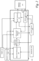
- Fig. 1 is a block diagram illustrating a "local" apparatus 100 for monitoring a person, according to some embodiments of the present invention.
- the apparatus 100 is configured for being connected to one or more sensors 102 and with a remote system 120.
- the apparatus 100 includes a sensor port 106, a memory unit 108, a timer 110, a processor 112, a local linking unit 114, and a remote linking unit 116.
- the apparatus 100 includes and is integral with a local user interface 118.
- the apparatus 100 is in wired or wireless communication with the local user interface 118.
- the one or more sensors 102 are associated with a bed of the monitored person, and are configured for producing first signals indicative of the presence or absence of the person on the bed.
- the sensors may include, for example, a pressure sensor located on or under the mattress, configured for being activated or deactivated when pressure is applied thereupon.
- the sensor includes a camera for monitoring the bed and an image processing unit configured for using the camera's images or feed for determining whether the person is or is not on the bed.
- the sensor may be any sensor that may be used for determining whether the person is in bed or not, and the apparatus 100 of the present invention may be configured for receiving data signals from one or more of any kinds of sensors.
- the apparatus 100 is connected to the one or more sensors 102 via the sensor port 106.
- the connection may be wired or wireless (e.g. Bluetooth, WiFi, or any other kind of wireless connection).
- the sensor port 106 is configured for receiving the first signals from the one or more sensors 102, and for providing the first signals to the processor 112.
- the processor 112 comprises a microprocessor, microcontroller, custom ASIC, and/or discrete circuitry selected on the basis of power consumption, size, processing speed, memory capacity, and other factors for performing all of the functionality of the apparatus 100.
- the timer 110 is configured for measuring time, and may be integral with the processor 112 as a function performed by processor 112 in accordance with machine-readable instructions stored in memory unit 108, or may comprise a distinct and separate hardware and/or firmware element, coupled to the processor.
- the memory unit 108 comprises one or more non-volatile data storage units, such as one or more hard disks, SD cards, disk-on-key drives, Flash memory, SRAM, or any other data storage unit.
- the memory unit 108 is configured for storing machine-readable instructions, and a set of parameters used to determine one or more alert conditions related to the person's use of the bed.
- the alert conditions define situations that may indicate an emergency. These situations are functions of the absence or presence of the monitored person on the bed at predetermined times and/or during predetermined time intervals. For example, one alert condition may correspond to a situation in which the monitored person is in bed after a predetermined wake-up time. This situation is unusual and may be indicative of the fact that the monitored person is not able to get out of bed - which is a potential emergency.
- the processor 112 receives the first signals, is in communication with the timer and the memory unit, and is configured to process the first signals and determine whether an emergency condition exists, according to a comparison of the first signals with the parameters, such as a time duration, expected bed times, wake times, exception times, etc., stored in the memory unit 108. In some embodiments of the present invention, the processor may also provide other information, such as a current time that the condition occurred, a current status indicative of presence or absence in bed, and a time interval since the status was last changed. After determining a current condition of the monitored person, the processor 112 then compares the current condition with alert conditions stored in memory unit 108, to determine whether the current condition is an alert condition.
- the processor 112 After determining a current condition of the monitored person, the processor 112 then compares the current condition with alert conditions stored in memory unit 108, to determine whether the current condition is an alert condition.
- the local communication device 128 may include speaker, a display, lights, and/or haptic devices. In this manner, the alarm/warning may be conveyed as a sound, an image or text, as a light which may be on or blinking, and/or by activating the haptic device (which may vibrate to convey the warning, for example).
- the local communication device 128 may include one or more of a touchscreen, a keyboard, a keypad, a button, an accelerometer, and a microphone for voice recognition.
- the adaptive snooze is configured to accommodate a monitored person who wakes up for an extended period in the night.
- the adaptive snooze may be in the form of a screen that prompts the monitored person to add additional time to the snooze. This allows the monitored person to be away from bed longer in the middle of the night in order to read or watch TV without triggering either a pre-alert alarm signal and/or an alarm alert signal. This feature may present a risk that a fall might go undetected for an increased length of time. Because of this greater risk, this form of adaptive snooze may be made available only if the monitored person and/or the caregivers/responders opt in.
- the reset module 206 is configured for receiving a reset signal from the local device 216 and/or from the remote system 214, and for generating a reset control signal in response to the reset signal.
- the reset signal is transmitted to the alert module 204, which in turn instructs the local device 216 to stop conveying the alert warning and the system device 120 to stop contacting the at least one caretaker, and/or to send a signal to the caretaker indicating that the condition associated with the alert has been taken care of.
- the undesirable condition includes one or more of the following conditions: (i) the person is out of bed during a bedtime period specified in the first data; (ii) the person is in bed after a wake-up time specified in the first data; and (iii) the person has been out of bed during the bedtime period for a time interval greater than a predetermined time interval specified in the first data.
- the alert module is configured for instructing the remote system 214 to contact the one or more caretakers and to inform them that the alert signal has ceased, such as in the case where a local user cancels the alert signal via local device 216.
- one of several caretakers contacts remote system 214 to indicate that the caretaker will take care of the problem, and remote system 214 contacts the other caretakers, informing them that one of the caretakers is taking care of the problem. In this manner, once a responder has taken the responsibility to check on the monitored person, the other responders are informed of this fact.
- the local device 216 can be set to communicate with the remote devices, such as smart phones, tablets, or computers in communication with remote system 214.
- the alert module is configured for checking its connection with the remote system 214. If the connection is successful, the alert module sends an alert alarm signal the remote system 214, to cause the remote system 214 to contact one or more remote devices. If the connection is unsuccessful, the alert module is configured to transmit an instruction signal to the local device 216, to instruct the local device 216 to contact the remote devices directly, such as by cellular data, Wi-Fi, or some other communication technology that may be included in local device 216.
- the alert module is configured for instructing the local device 216 to stop contacting responders, and optionally to inform responders that the alert signal has ceased, in response to a reset signal.
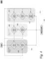
- Fig. 3 is a block diagram illustrating one embodiment of a system of the present invention, which enables communication with a responder's communication device via two different paths.
- a system 300 is provided for monitoring a person.
- the system includes a local apparatus 304 and a remote apparatus 306.
- the local apparatus 304 is similar to the apparatus 100 of Fig. 1 .
- the remote apparatus 306 is similar to the remote system 120 of Fig. 1 , and may include a server or a call center.
- the local apparatus 304 receives signals from the sensor(s) 302 and is configured for determining whether an undesirable condition is occurring with respect to a monitored person's use of a bed, as explained in the embodiments above. If an undesirable condition occurs, the local apparatus 304 checks its connection with the remote apparatus 306. If the connection is successful, the local apparatus transmits an alert signal to the remote apparatus 306.
- the remote apparatus 306 contacts one or more remote communication devices associated with respective responders, such as cellular telephones, tablet computers, etc., to convey a warning.
- the warning may be in the form of an SMS message, email, or a voice message.
- the local apparatus 304 contacts the one or more responders directly.
- the local apparatus 304 and remote apparatus 306 are connected to each other via the Internet.
- contact between the local apparatus 304 or the remote apparatus 306 with one or more remote communication devices is via a phone network, such as a cellular network, or a wide-area network, such as the Internet.
- the local apparatus 304 is configured for receiving a reset instruction/signal from the one or more remote communication devices 308 and for conveying the reset signal to the remote apparatus 306.
- the local apparatus 304 is configured for stopping the conveying of a local warning, and optionally to stop sending alert signals to the remote communication devices 308.
- the remote apparatus 306 is configured for ceasing to send alert signals to the remote communication devices 308.
- the remote apparatus 306 is configured for receiving a reset instruction/signal from the one or more remote communication devices 308 and for conveying the reset signal to the local apparatus 304.
- the local apparatus In response to the reset signal, the local apparatus is configured for stopping the conveying of a local warning.
- the remote apparatus In response to the reset signal, the remote apparatus is configured for ceasing to send alert signals to the remote communication devices 308.
- the remote and the local apparatuses in response to the reset signal, are configured for transmitting a cancellation signal to the at least one remote communication device 308.
- the cancellation signal causes the at least one remote communication device 308 to convey a message to the respective responder indicating that the alert has ceased.
- the local device 304 is configured for conveying a local pre-alert warning when an undesirable condition has been identified, for example, an audible alert. If no input has been received by the local device from a person within proximity to the local device 304 within a predetermined time interval, the local device 304 is configured to generate the alert signal.
- a local pre-alert warning when an undesirable condition has been identified, for example, an audible alert. If no input has been received by the local device from a person within proximity to the local device 304 within a predetermined time interval, the local device 304 is configured to generate the alert signal.
- the system 300 includes a second remote apparatus 307.
- the local apparatus can send the alert signal to the second remote apparatus, and the second remote apparatus can relay the alert signal to the remote communication device(s) 308.
- the first remote apparatus 306 may be a server, while the second remote apparatus 307 may be a call center.
- the sensor(s) 302 is (are) part of the system 300.
- Fig. 4 is a flowchart 400 illustrating a method for generating a pre-alert signal indicative of a possible emergency, according to some embodiments of the present invention.
- the processor 112 of Fig. 1 and the analysis module 202 of Fig. 2 perform the following functions: a not-in-bed check, a not-out-of-bed check, and a not-back-in-bed check.
- the not-in-bed check determines whether the monitored person is in bed just after a predetermined start of a bedtime period.
- the not-out-of-bed check determines whether the monitored person is still in bed just after a predetermined end of the bedtime period.
- the not-back-in-bed check determines whether the monitored person is in bed during the bedtime period, while allowing the monitored person to leave the bed for a certain grace time interval, for example to use the bathroom.
- the time is checked from timer 110 and the data from the memory module 108 or 212 (of Fig. 1 and Fig. 2 , respectively) is used by processor 112 to determine whether the bedtime period has just started. If the bedtime period has just started, the monitored person is supposed to be in bed, and the not-in-bed check is performed by processor 112. Thus, at 404 the data received from the sensors is used by processor 112 to determine whether the monitored person is in bed, for example by checking if there is pressure on the pressure pad located on or under the mattress. If the monitored person is in bed, it is safe to assume that the monitored person does not need help. Thus a loop is effected back to the beginning of the process operation.
- processor 112 If the monitored person is not in bed, there is a chance that the monitored person could not reach the bed and may need assistance. Thus, at 405, processor 112 generates a pre-alert signal and sends the pre-alert signal to the local output unit, e.g., local user interface 118 and/or local communication device 128.
- the local output unit e.g., local user interface 118 and/or local communication device 128.
- processor 112 determines whether the bedtime period has just ended. If the bedtime period has just ended, the monitored person is not supposed to be in bed any longer, and the not-out-of-bed check is performed by processor 112. Thus, data received from the sensors is used at 408 to determine whether the person is in bed. If the monitored person is not in bed, it is safe to assume that the monitored person has followed his/her usual schedule and is not in need of assistance. Thus loop is executed back to the beginning of the process. If the monitored person is still in bed, a deviation from the schedule is detected, and the monitored person may not be in a condition to leave the bed. Thus, processor 112 generates a pre-alert signal at 405, and sends the pre-alert signal to the local output unit, e.g., local user interface 118 and/or local communication device 128.
- the local output unit e.g., local user interface 118 and/or local communication device 128.
- processor 112 determines the length of time that the person has been out of bed. This is because, the monitored person may get out of bed in the middle of the bedtime period to go to the bathroom or get a drink of water. Processor 112 determines a time that the person was determined to be not in bed, and monitors for when the person returns to the bed 414. If the length of time in which the monitored person is out of bed does not exceed the predetermined grace time interval, the monitored person may be safe and may have voluntarily left the bed. Thus, a loop is executed back to the start of the process.
- processor 112 generates a pre-alert signal at 405 and the pre-alert signal is sent to the local output unit.
- the primary power source of the apparatus 100 of Fig. 1 is an electrical plug into mains power, and the apparatus 100 also contains an internal battery backup which allows the apparatus to continue operating during a power interruption.
- the apparatus continually monitors the power source and if the power is interrupted, the control unit generates a pre-alert signal.
- Fig. 5 is a flowchart 500 illustrating a method for determining whether the pre-alert signal is indicative of an actual emergency, according to some embodiments of the present invention.
- a pre-alert signal was generated at 405, as the monitored person has departed from his/her usual schedule or as a consequence of a power failure. This, however, may or may not indicate a state of emergency. It is possible that the power failure is short, or that the monitored person has decided to stay up longer than usual, sleep longer than usual, or stay out of bed longer than usual during the bedtime period.
- the pre-alert signal is generated and a pre-alert warning is emitted by the local output unit at 502
- the monitored person can respond to the pre-alert warning to indicate that he/she is not in need of assistance.
- the local output unit issues the pre-alert warning, for example via a sound and/or an image on a display.
- the image on the display may include a countdown, showing the time left before an alert signal is sent to the remote system.
- a check at 504 is made by processor 112 to determine whether a grace period for the monitored person's response, or a grace period within which the power is restored (e.g., 30 seconds, 1 minute, 2 minutes, etc.) has expired. If either of the grace periods has expired, it is assumed that the power failure may affect the operation of the monitoring system or that monitored person encountered a difficulty that prevented him/her from reaching the local input unit and signal that he/she is not in need of assistance. Thus, an alert signal is generated at 508 by processor 112, and sent to the remote system to alert responders of a potential emergency situation.
- a grace period for the monitored person's response e.g., 30 seconds, 1 minute, 2 minutes, etc.
- the check to determine whether the grace period has expired may be performed repeatedly by processor 112, until either the power is restored or the grace period has expired (whichever occurs earlier). If the power is restored within the grace period, the system may be reset. If the grace period has expired, the alert signal may be generated.
- the response may be effected, for example, by pressing a key on a keyboard, a virtual button on a touch screen, or a button of the local input unit 124 or on the local communication device 128 in communication with the apparatus 100 of Fig. 1 . If a response was detected, the pre-alert warning is turned off, and the system is reset by processor 112 at 514.
- One such event is the connection of a sensor 102 to the apparatus 100 of the monitoring system.
- the sensor 102 includes a pressure pad
- the pad is connected at all times for the unit to function correctly.
- pads have a usable lifetime before they need to be replaced, and that they may become inadvertently disconnected from apparatus 100 during use. Taking these facts into account, the apparatus 100 may continually monitor to determine if a pad is connected or not, regardless of whether pressure is applied on the pad.
- processor 112 determines that a pad has become disconnected, processor 112 generates a pre-alert signal at 1100, and a warning is conveyed by local user interface 118 and/or local communication device 128 at 1102. If processor 112 determines that the pad has been disconnected for a predetermined amount of time (grace period) or longer (as seen in the check of 1104), the pre-alert warning is stopped/removed at 1106, and an alarm signal is generated by processor 112 at 1108. If the pad is re-connected/restored before the end of the grace period (as shown in the check of 1110), the system is reset by processor 112 at 1112. The grace period delay provides the monitored person or a helper of the monitored person with enough time to remove their current bed pad and replace it with a new one or to check the connection to apparatus 100 and/or the pad, without generating an alarm signal and worrying the caretakers.
- the grace period delay provides the monitored person or a helper of the monitored person with enough time to remove their current bed pad
- Pressure pads used are manufactured to provide a specific product lifetime. Pads may be rated, for example, for 30 days, 6 months, 1 year, or 2 years. The lifetime is typically marked on the pad.
- the processor 112 queries a user whether the pad is a new or old via local user interface 118 and/or local communication device 128. If the pad is new, processor 112 prompts the user to input the pad's time rating. Processor 112 stores this information, along with the current date, in memory 108, and may provide the user with a SMS message within a predetermined time period (e.g., 10 days, 30 days) prior to pad expiration, indicating that a new replacement pad should be ordered. Optionally, the apparatus sends out another notification, via local user interface 118 and/or local communication device 128, several days before the pad's actual expiration date to remind the user to install a new pad as soon as possible to ensure proper operation of the apparatus. ⁇
- a predetermined time period e.g. 10 days, 30 days
- Fig. 6 is a flowchart 600 illustrating a method for generating an alert warning, according to some embodiments of the present invention.
- an alert signal is generated at 602 by processor 112
- the alert signal is sent to the local output unit 124 via local linking unit 114, whereby the local output unit 124 generates an alert warning, such as an audible, visual, and/or tactile alert.
- the alert warning may prompt the monitored person to acknowledge the warning, at 604.
- a flashing light is activated at 606 and an audible alarm is activated at 608 in the local output unit 124. If the monitored person is in the care of a nurse, a nurse call signal may be activated at 610 to inform the nurse about the alert warning.
- a remote notification may be sent at 612 by apparatus 100 directly to the remote communication devices 122 of one or more responders, or to the remote system 120 - which is to send the notifications to the remote communication devices.
- the remote system may generate an SMS, email, voice call, or data alert, by sending such notifications to one or more predefined phone numbers, IP addresses, email addresses, etc that are pre-stored in memory 108 and provided by apparatus 100, or pre-stored at remote system 120.
- an alert signal is generated as a response to a power failure, the SMS, voice call, or data alert, is activated immediately without displaying the alert warning in the local output unit 124.
- Fig. 7 is a flowchart 700 illustrating a method for contacting a call center if a server is not responsive, according to some embodiments of the present invention.
- remote system 306 or 120 e.g. server
- apparatus 100/304 e.g. server
- the call center is manned by human personnel.
- the call center is automated.
- Fig. 8 is a flowchart illustrating a method for resetting a monitoring system/apparatus of the present invention, to inform previously contacted responders that the monitored person is being looked after, according to some embodiments of the present invention.
- a reset signal is generated at 802, for example, from local user interface 118 and/or local communication device 128, it is sent to the local output unit 124 to stop the local alert warning.
- a warning prompting the monitored person to acknowledge the warning is removed from the display of the output unit 124 at 804.
- the flashing light is deactivated at 806 and the audible alarm is deactivated at 808 in the local output unit 124.
- the nurse call signal is deactivated by processor 112 at 810.
- a remote reset notification may be sent to the remote communication devices 122, and/or to the remote system 120 at 812.
- the remote system 120 may generate a notification to notify responders that the alert has stopped, and send the notification to one or more predefined phone numbers, email addresses, IP addresses, etc.
- Fig. 9 is a flowchart illustrating a method for using an SMS generating system to informing one or more responders that a monitored person needs help, according to some embodiments of the present invention.
- the apparatus 100 of Fig. 1 (with or without the help of the remote system 120) attempts to send the alert signal to one or more remote communication devices associated with respective remote responders. For this purpose, two different paths of communication may be attempted for redundancy.
- the alert signal is handed off to an internet server (remote system 120) which has the ability to send and receive SMS messages and act accordingly.
- the server 120 accepts the alert signal
- the local apparatus 100 or 304 simply queries the server 120 for updates. More specifically, the local apparatus checks if the communication with the server is successful (server returns success) at 904. If so, after a predetermined time interval (e.g., 10, 20, 30 seconds) shown in 906, the local apparatus requests an update from the server at 908 and checks if communication with the server is successful (server returns success) at 910.
- a predetermined time interval e.g. 10, 20, 30 seconds
- the server sends SMS's to caretakers/responders/other interested parties such as friends or family, and checks at 912 whether at least one of the caretakers/responders/other interested parties has acknowledged the SMS (alert confirmed on server). If at least one responder has acknowledged the SMS, the apparatus 100 is reset at 904. If none of the responders acknowledges the SMS, a check is made at 916 by server 120 to determine if the alert is confirmed locally at the apparatus 100. If the alert was generated in response corresponds to a probable need of assistance of the monitored person, the alert is confirmed locally when the monitored person or a caretaker has reached the input unit of the monitoring system and instructed the alert to stop.
- the alert is confirmed locally when power is restored. If the alert is confirmed locally, the confirmation of the local acknowledgment is sent to the server at 918 by the apparatus 100, the server 120 stops contacting the responders, and the apparatus 100 is reset at 914. If the server fails to send SMS's and the alert signal is not confirmed locally, the process loops to step 906 in which apparatus 100 waits a predetermined time interval before contacting the server 120 again.
- connection between the apparatus 100 and the server 120 is effected via a cellular data connection.
- the apparatus 100 includes a transmission device (e.g. modem, cellular ASIC, Wi-Fi transceiver, etc.) configured for sending notifications directly to responders' remote communication devices without having to rely on the server 120.
- a transmission device e.g. modem, cellular ASIC, Wi-Fi transceiver, etc.
- the local apparatus 100 handles the sending of notifications.
- the local apparatus 100 sets a count value to 1 at 918, sends SMS notifications to all responders at 920, waits a predetermined time interval (e.g., 30, 60, 120 seconds) at 922, and checks whether any of the SMS's were acknowledged at 924.
- the system is reset at 914.
- a check is performed to determine whether the alert was confirmed locally at 926. If the alert is confirmed locally, the confirmation is sent to the server at 928 and the apparatus 100 is reset at 914.
- the system If no SMS's are acknowledged, and the alert is not confirmed locally, the system generates a "no response" warning.
- the local apparatus 100 adds 1 to the SMS count value at 930, loops to the sending of the SMS and performs the subsequent steps, as described above. If this loop has occurred a predetermined number of times, and the SMS count value is equal to a predetermined value (e.g., 2, 3, 5) at the check 932, the local apparatus 100 generates a "no response" signal.
- the "no response" signal causes the local apparatus 100 to contact a call center in order to attempt contacting at least one responder, as shown in Fig. 7 .
- Fig. 10 is a flowchart illustrating a method for using a call center to inform one or more caregivers that a monitored person needs help, according to some embodiments of the present invention.
- the method of Fig. 10 follows the method of Fig. 9 if a "no response" warning is generated.
- a notification to a call center is sent via a server at 1000. If communication with the server is successful at the check of 1002, the server contacts the call center, keeps contacting the call center to receive a confirmation that at least one SMS has been acknowledged, and keeps contacting the apparatus 100 to receive a confirmation that the emergency condition has been confirmed locally, until one of these conditions is fulfilled (steps 1004-1014 ). If one of these conditions is fulfilled, the server 120 is reset at 1016.
- the local apparatus 100 itself attempts contacting the call center.
- the local apparatus 100 instructs the call center to send SMS notifications to the responders at 1018, and waits for a predetermined time interval at 1020, to receive a notification from the call center that the SMS notifications have been sent at 1022. If the SMS notifications have not been sent, e.g., the predetermined time interval expires without receiving an acknowledgement from the call center, the process loops to the step 1018 of instructing the call center. If the SMS notification have been sent, the apparatus 100 contacts the call center to determine whether any of the SMS notifications have been acknowledged by the caregivers at 1024.
- apparatus 100 receives an indication of such from the call center, and the apparatus 100 is reset at 1016. If none of the notifications is acknowledged, the local apparatus checks whether the alert has been confirmed locally at 1026. If this is the case, the server is informed of the local confirmation at 1028 and the monitoring system is reset. Otherwise, the process loops back to checking whether any SMS has been acknowledged.
- the process of Fig. 10 will not stop until at least one of the SMS notifications has been acknowledged by a responder or the alert is acknowledged (confirmed) locally at the local apparatus 100.
- the call center may be manned by human personnel or may be automatic.
- the call center uses a voice API system.
- the voice API system places a call to a responder and reads, using text-to-voice software, a message which alerts the responder as to the active alert and its severity.
- the voice API system interacts with the caregiver by providing caregiver with a menu of options. One of the options may involve pressing a predetermined button on the phone to reply to the call center's message.
- the API system may be used instead of the sending SMS messages, or as an additional option, used for example as a "last resort" contact method after several rounds of text messages have been sent with no response.
Landscapes
- Business, Economics & Management (AREA)
- Emergency Management (AREA)
- Physics & Mathematics (AREA)
- General Physics & Mathematics (AREA)
- Health & Medical Sciences (AREA)
- Gerontology & Geriatric Medicine (AREA)
- General Health & Medical Sciences (AREA)
- Psychiatry (AREA)
- Psychology (AREA)
- Social Psychology (AREA)
- Engineering & Computer Science (AREA)
- Computer Security & Cryptography (AREA)
- Alarm Systems (AREA)
- Emergency Alarm Devices (AREA)
Claims (11)
- System (300) zum Überwachen einer Person, wobei das System (300) durch Folgendes gekennzeichnet ist:
ein lokales Gerät (304, 100), umfassend:einen Sensoranschluss (106), der dazu konfiguriert ist, erste Signale von einem Sensor (102, 302) zu empfangen, der einem Bett der Person zugeordnet ist;eine Speichereinheit (108) zum Speichern maschinenlesbarer Anweisungen und eines Satzes von Parametern, die verwendet werden,um einen oder mehrere Warnzustände zu bestimmen, die die Verwendung des Bettes durch die Person betreffen;einen Zeitgeber (110), der dazu konfiguriert ist, die Zeit zu messen;einen Prozessor (112), der mit dem Sensoranschluss (106), mit dem Zeitgeber (110) und mit dem Speicher (108) gekoppelt ist, um die maschinenlesbaren Anweisungen auszuführen, die das lokale Gerät (304, 100) zu Folgendem veranlassen:Empfangen der ersten Signale von dem Sensor (102, 302) über den Sensoranschluss (106) und Bestimmen daraus, ob sich die Person in dem Bett oder nicht in dem Bett befindet;Bestimmen von Zeitinstanzen und Zeitdauern, die der Person, die sich in dem Bett und außerhalb des Bettes befindet, zugeordnet sind, basierend auf den ersten Signalen und auf Zeitmessungen durch den Zeitgeber (110);Vergleichen der Zeitinstanzen und Zeitdauern mit mindestens einigen der Parameter in dem Satz von Parametern, um zu bestimmen, ob ein Warnzustand der einen oder der mehreren Warnzustände eingetreten ist;Erzeugen eines Warnalarmsignals, wenn der Warnzustand eingetreten ist; und Abbrechen des Warnalarmsignals als Reaktion auf eine Abbruchanweisung;eine lokale Verknüpfungseinheit (114), die dazu konfiguriert ist, mit einer lokalen Benutzerschnittstelle (118) verbunden zu werden und mit der lokalen Benutzerschnittstelle (118) zu kommunizieren, sodass die lokale Benutzerschnittstelle (118) dazu konfiguriert ist, das Warnsignal zu empfangen und eine lokale Alarmmeldung in der Nähe der lokalen Benutzerschnittstelle (118) zu übermitteln, und eine Abbruchanweisung von einer oder mehreren Personen in der Nähe des lokalen Geräts (304, 100) zu empfangen, um das Warnalarmsignal abzubrechen;eine entfernte Verknüpfungseinheit (116), die dazu konfiguriert ist, mit einem entfernten Gerät (306, 120) verbunden zu werden und mit dem entfernten Gerät (306, 120) zu kommunizieren;
unddas entfernte Gerät (306, 120), das sich entfernt von dem Prozessor 112 und der lokalen Benutzerschnittstelle 118 befindet, wobei sich das entfernte Gerät (306, 120) in Kommunikation mit dem Prozessor (112) befindet und zu Folgendem konfiguriert ist:zum Empfangen des Warnalarmsignals und Übermitteln einer entfernten Alarmwarnung an eine oder mehrere entfernte Kommunikationsvorrichtungen (122), die jeweiligen Respondern zugeordnet sind, die sich entfernt von dem lokalen Gerät (100, 304) und von dem entfernten Gerät (120, 306) befinden, wobei die entfernten Kommunikationsvorrichtungen (122) physisch von dem entfernten Gerät (120, 306) getrennt sind; undzum Empfangen einer ersten Abbruchanweisung, die von dem einen oder den mehreren Respondern über jeweilige entfernte Kommunikationsvorrichtungen übermittelt wird, um das Warnalarmsignal abzubrechen; undÜbertragen der ersten Abbruchanweisung an den Prozessor (112) über die entfernte Verknüpfungseinheit (116), wodurch der Prozessor veranlasst wird, das Warnalarmsignal abzubrechen. - System nach Anspruch 1, wobei:vor dem Erzeugen des Warnalarmsignals der Prozessor (112) dazu konfiguriert ist, das lokale Gerät (100, 304) zu veranlassen, ein Vorwarnalarmsignal zu erzeugen, wenn der Warnzustand eingetreten ist, wobei das Vorwarnalarmsignal die Personen in der Nähe des lokalen Geräts (100, 304) benachrichtigt, dass ein Warnzustand eingetreten ist;die lokale Verknüpfungseinheit (114) ferner dazu konfiguriert ist, das Vorwarnalarmsignal zu empfangen und einen Vorwarnalarm in der Nähe der lokalen Benutzerschnittstelle (118) zu übermitteln, und eine zweite Abbruchanweisung zu empfangen, die von einer der Personen in der Nähe des lokalen Geräts (100, 304) übermittelt wird, um den Vorwarnalarm abzubrechen;wobei der Prozessor (112) dazu konfiguriert ist, den Vorwarnalarm als Reaktion auf das Empfangen der zweiten Abbruchanweisung abzubrechen; undwobei der Prozessor (112) dazu konfiguriert ist, das lokale Gerät (100, 304) zu veranlassen, das Warnsignal nur dann zu erzeugen, wenn der Warnzustand für eine vorbestimmte Zeitspanne anhält, ohne abgebrochen zu werden.
- System nach Anspruch 1 oder 2, ferner umfassend einen Transmitter, der mit dem Prozessor (112) gekoppelt ist und dazu konfiguriert ist, das Warnalarmsignal an eine lokale Kommunikationsvorrichtung (128) zu übertragen, die physisch von dem lokalen Gerät (100, 304) getrennt ist und sich innerhalb eines der überwachten Person zugeordneten Raums befindet, wodurch die lokale Kommunikationsvorrichtung (128) veranlasst wird, die lokale Alarmmeldung an Personen zu übermitteln, die sich in der Nähe der lokalen Kommunikationsvorrichtung (128) befinden, um zu benachrichtigen, dass einer der Warnzustände eingetreten ist.
- System nach Anspruch 2, ferner umfassend einen Transmitter, der dazu konfiguriert ist, das Vorwarnalarmsignal an eine lokale Kommunikationsvorrichtung (128) zu übertragen, wodurch die lokale Kommunikationsvorrichtung (128) veranlasst wird, den Vorwarnalarm an Personen zu übermitteln, die sich in der Nähe der lokalen Kommunikationsvorrichtung (128) befinden, um zu benachrichtigen, dass einer der Warnzustände eingetreten ist;
wobei der Transmitter dazu konfiguriert ist, das Warnalarmsignal nur dann an die lokale Vorrichtung (128) zu übermitteln, wenn das Vorwarnalarmsignal nicht innerhalb der vorbestimmten Zeitspanne abgebrochen worden ist. - System nach Anspruch 3, ferner umfassend einen Empfänger, der dazu konfiguriert ist, ein Abbruchsignal von der lokalen Kommunikationsvorrichtung (128) zu empfangen, damit das lokale Gerät (100, 304) das Warnalarmsignal abbricht;
wobei der Prozessor (112) dazu konfiguriert ist, das Warnalarmsignal bei Empfang des Abbruchsignals abzubrechen. - System nach Anspruch 4, ferner umfassend einen Empfänger, der dazu konfiguriert ist, ein Abbruchsignal von der lokalen Kommunikationsvorrichtung (128) zu empfangen, damit das lokale Gerät (100, 304) das Warnalarmsignal und/oder das Vorwarnalarmsignal abbricht;
wobei der Prozessor (112) dazu konfiguriert ist, das Warnalarmsignal und/oder das Vorwarnsignal bei Empfang des Abbruchsignals abzubrechen. - System nach Anspruch 1, wobei der eine oder die mehreren Warnzustände mindestens eines von Folgendem umfassen:die Person befindet sich außerhalb des Betts während einer Schlafzeitspanne, die in dem Satz von Parametern spezifiziert ist;die Person befindet sich in dem Bett nach einer Aufwachzeit, die in dem Satz von Parametern spezifiziert ist; unddie Person hat sich während der Schlafenszeitspanne für ein Zeitintervall außerhalb des Bettes aufgehalten, das größer ist als ein vorbestimmtes Zeitintervall, das in dem Satz von Parametern spezifiziert ist.
- System nach Anspruch 4, wobei die maschinenlesbaren Anweisungen ferner Anweisungen umfassen, die das Gerät zu Folgendem veranlassen:Erzeugen einer Benachrichtigung zur Übertragung an das entfernte Gerät (120, 306) als Reaktion auf das Empfangen der Abbruchanweisung, wobei die Benachrichtigung das entfernte Gerät (120, 306) darüber informieren soll, dass der Vorwarnalarm erzeugt und dann abgebrochen wurde; undwobei die entfernte Verknüpfungseinheit (116) ferner dazu konfiguriert ist, die Benachrichtigung zu übertragen.
- System nach Anspruch 1, wobei:das entfernte Gerät (120, 306) mindestens eines von einem Callcenter und einem Server umfasst;das Callcenter dazu konfiguriert ist, die entfernte Alarmwarnung an die eine oder die mehreren entfernten Kommunikationsvorrichtungen (122) über eines oder mehrere von Folgendem zu übermitteln: SMS und Sprach-API-System; undder Server dazu konfiguriert ist, die entfernte Alarmwarnung an die eine oder die mehreren entfernten Kommunikationsvorrichtungen (122) über eines oder mehrere von Folgendem zu übermitteln: SMS, E-Mail, Sprachanruf und Datenwarnung.
- System nach Anspruch 1, umfassend die lokale Benutzerschnittstelle (118), sodass die lokale Benutzerschnittstelle (118) einstückig mit dem lokalen Gerät (100. 304) ist.
- System nach einem der Ansprüche 1-10, wobei das entfernte Gerät (120, 306) dazu konfiguriert ist, mit dem Prozessor (112) über die entfernte Verknüpfungseinheit (116) durch ein Weitverkehrsnetz und/oder ein Mobilfunknetz zu kommunizieren.
Applications Claiming Priority (2)
| Application Number | Priority Date | Filing Date | Title |
|---|---|---|---|
| US14/574,670 US9558641B2 (en) | 2013-12-18 | 2014-12-18 | System and method for monitoring a person |
| PCT/IB2016/050888 WO2016098090A2 (en) | 2014-12-18 | 2016-02-18 | System and method for monitoring a person |
Publications (3)
| Publication Number | Publication Date |
|---|---|
| EP3284072A2 EP3284072A2 (de) | 2018-02-21 |
| EP3284072A4 EP3284072A4 (de) | 2019-05-22 |
| EP3284072B1 true EP3284072B1 (de) | 2025-07-02 |
Family
ID=56127785
Family Applications (1)
| Application Number | Title | Priority Date | Filing Date |
|---|---|---|---|
| EP16729175.6A Active EP3284072B1 (de) | 2014-12-18 | 2016-02-18 | System und verfahren zur überwachung einer person |
Country Status (7)
| Country | Link |
|---|---|
| US (2) | US9558641B2 (de) |
| EP (1) | EP3284072B1 (de) |
| JP (1) | JP2018501594A (de) |
| CN (1) | CN107408329A (de) |
| CA (1) | CA2971575C (de) |
| GB (1) | GB2549665B (de) |
| WO (1) | WO2016098090A2 (de) |
Families Citing this family (16)
| Publication number | Priority date | Publication date | Assignee | Title |
|---|---|---|---|---|
| US20150194032A1 (en) * | 2014-01-06 | 2015-07-09 | I-Saiso Inc. | Wellbeing monitor |
| US10489661B1 (en) | 2016-03-08 | 2019-11-26 | Ocuvera LLC | Medical environment monitoring system |
| US10460590B2 (en) * | 2016-07-26 | 2019-10-29 | Tyco Integrated Security, LLC | Method and system for mobile duress alarm |
| US10600204B1 (en) | 2016-12-28 | 2020-03-24 | Ocuvera | Medical environment bedsore detection and prevention system |
| US10602339B2 (en) * | 2017-05-17 | 2020-03-24 | Hand Held Products, Inc. | Systems and methods for improving alert messaging using device to device communication |
| US11330418B2 (en) | 2017-06-20 | 2022-05-10 | Otis Elevator Company | Lone worker safely check |
| JP6893837B2 (ja) * | 2017-07-10 | 2021-06-23 | ソフトバンク株式会社 | 見守り支援システム、見守り支援プログラム及び見守り支援方法 |
| US20190304283A1 (en) | 2017-08-03 | 2019-10-03 | Tidi Products, Llc | Integrated Belt And Sensor For Alarm For Patient Furniture |
| US20210254644A1 (en) | 2017-08-03 | 2021-08-19 | Tidi Products, Llc | Integrated Belt and Sensor for Alarm for Patient Furniture |
| US11210922B2 (en) | 2018-10-22 | 2021-12-28 | Tidi Products, Llc | Electronic fall monitoring system |
| US10692346B2 (en) | 2018-10-22 | 2020-06-23 | Tidi Products, Llc | Electronic fall monitoring system |
| US11109213B2 (en) * | 2019-05-17 | 2021-08-31 | EaseAlert, LLC | Pre-alert system for first responders |
| CA3133535A1 (en) * | 2019-06-21 | 2020-12-21 | Stryker Corporation | Patient support apparatus with caregiver reminders |
| CN110555978A (zh) * | 2019-09-06 | 2019-12-10 | 上海长征医院 | 一种防跌倒和坠床的报警床垫 |
| MX2023012596A (es) | 2021-05-11 | 2023-11-06 | Tidi Products Llc | Sistema y metodo de monitoreo de paciente. |
| CN113689956A (zh) * | 2021-09-22 | 2021-11-23 | 合肥学院 | 智慧社区健康监护管理系统及方法 |
Family Cites Families (28)
| Publication number | Priority date | Publication date | Assignee | Title |
|---|---|---|---|---|
| JP3352935B2 (ja) * | 1997-07-10 | 2002-12-03 | 松下電器産業株式会社 | 離床在床検知システム、監視システム |
| US7629890B2 (en) * | 2003-12-04 | 2009-12-08 | Hoana Medical, Inc. | System and methods for intelligent medical vigilance with bed exit detection |
| JP2004065471A (ja) * | 2002-08-05 | 2004-03-04 | Nippon Colin Co Ltd | 患者監視システム |
| JP4058310B2 (ja) * | 2002-09-09 | 2008-03-05 | 株式会社山武 | 睡眠状態判定装置及び就寝モニタリングシステム |
| JP2005275776A (ja) * | 2004-03-24 | 2005-10-06 | Nohmi Bosai Ltd | 要救助通報装置 |
| US7129833B2 (en) * | 2004-07-23 | 2006-10-31 | Innovalarm Corporation | Enhanced fire, safety, security and health monitoring and alarm response method, system and device |
| US7570152B2 (en) * | 2005-08-19 | 2009-08-04 | Bed-Check Corporation | Method and apparatus for temporarily disabling a patient monitor |
| JP2007124312A (ja) * | 2005-10-28 | 2007-05-17 | Keakomu:Kk | ナースコールシステム |
| US9728061B2 (en) * | 2010-04-22 | 2017-08-08 | Leaf Healthcare, Inc. | Systems, devices and methods for the prevention and treatment of pressure ulcers, bed exits, falls, and other conditions |
| AU2010229043A1 (en) * | 2009-03-26 | 2011-10-13 | John Brasch | Personal monitoring system |
| US8717181B2 (en) * | 2010-07-29 | 2014-05-06 | Hill-Rom Services, Inc. | Bed exit alert silence with automatic re-enable |
| US20120025990A1 (en) * | 2010-07-29 | 2012-02-02 | Tallent Dan R | Bed exit alert silence with automatic re-enable |
| JP2012070335A (ja) * | 2010-09-27 | 2012-04-05 | Aiphone Co Ltd | 集合住宅インターホンシステム |
| US8723677B1 (en) * | 2010-10-20 | 2014-05-13 | Masimo Corporation | Patient safety system with automatically adjusting bed |
| CN102280011B (zh) * | 2011-06-09 | 2013-06-19 | 无锡国科微纳传感网科技有限公司 | 周界安防处警方法及系统 |
| CN202167121U (zh) * | 2011-06-13 | 2012-03-14 | 袁书胜 | 远程视音频多功能报警系统 |
| US9466877B2 (en) * | 2011-11-29 | 2016-10-11 | Hill-Rom Services, Inc. | Hospital bed having near field communication capability |
| US20130250080A1 (en) * | 2012-03-23 | 2013-09-26 | Megan Farrell | Modularized mobile health and security system |
| US10446003B2 (en) * | 2012-10-16 | 2019-10-15 | Huntleigh Technology Limited | System and methods for monitoring and entrapment prevention for a person disposed in a bed |
| CN103903406A (zh) * | 2012-12-30 | 2014-07-02 | 王方淇 | 一种突发事件监测通知方法及系统 |
| US20140232556A1 (en) * | 2013-02-19 | 2014-08-21 | Rondish Company Limited | Wireless, multi-point patient monitoring system |
| CN203179224U (zh) * | 2013-04-09 | 2013-09-04 | 南京理工大学 | 道路事故自动报警及二次事故预警装置 |
| US20150035671A1 (en) * | 2013-08-01 | 2015-02-05 | Rondish Company Limited | Intelligent Reset System and Method For Patient Monitoring Pad |
| CN103431868A (zh) * | 2013-08-15 | 2013-12-11 | 费军 | 一种无人值守伤员的中央监护定位系统 |
| US20150095054A1 (en) * | 2013-09-30 | 2015-04-02 | Newcare Solutions, Llc | Monitoring systems and method |
| TWI539400B (zh) * | 2013-12-18 | 2016-06-21 | 美思科技股份有限公司 | 臨床資訊管理系統 |
| CN203894889U (zh) * | 2014-04-17 | 2014-10-22 | 上海豫光智能工程有限公司 | 基于gprs无线技术的脉冲电子围栏报警系统 |
| CN105279913B (zh) * | 2014-06-30 | 2018-06-26 | 惠州市德赛西威汽车电子股份有限公司 | 一种车辆道路事故救援呼叫系统及方法 |
-
2014
- 2014-12-18 US US14/574,670 patent/US9558641B2/en active Active - Reinstated
-
2016
- 2016-02-18 JP JP2017551392A patent/JP2018501594A/ja active Pending
- 2016-02-18 GB GB1711569.2A patent/GB2549665B/en not_active Expired - Fee Related
- 2016-02-18 EP EP16729175.6A patent/EP3284072B1/de active Active
- 2016-02-18 CA CA2971575A patent/CA2971575C/en active Active
- 2016-02-18 WO PCT/IB2016/050888 patent/WO2016098090A2/en not_active Ceased
- 2016-02-18 CN CN201680010308.1A patent/CN107408329A/zh active Pending
-
2017
- 2017-01-30 US US15/420,054 patent/US20170140630A1/en not_active Abandoned
Also Published As
| Publication number | Publication date |
|---|---|
| GB201711569D0 (en) | 2017-08-30 |
| CA2971575A1 (en) | 2016-06-23 |
| WO2016098090A2 (en) | 2016-06-23 |
| US20170140630A1 (en) | 2017-05-18 |
| US9558641B2 (en) | 2017-01-31 |
| EP3284072A2 (de) | 2018-02-21 |
| US20160196733A1 (en) | 2016-07-07 |
| EP3284072A4 (de) | 2019-05-22 |
| WO2016098090A3 (en) | 2016-08-18 |
| GB2549665B (en) | 2020-02-12 |
| CN107408329A (zh) | 2017-11-28 |
| JP2018501594A (ja) | 2018-01-18 |
| GB2549665A (en) | 2017-10-25 |
| CA2971575C (en) | 2021-08-31 |
Similar Documents
| Publication | Publication Date | Title |
|---|---|---|
| CA2971575C (en) | System and method for monitoring a person | |
| US10475331B2 (en) | Monitoring activity of an individual | |
| US9565718B2 (en) | System and method for detecting and transmitting medical device alarm with a smartphone application | |
| CN107683501B (zh) | 用于对人进行主动监控的系统和方法 | |
| US7589637B2 (en) | Monitoring activity of an individual | |
| US20120154155A1 (en) | Personal monitoring system | |
| WO2008010955A2 (en) | Remote device for a monitoring system | |
| US20220301407A1 (en) | Wireless patient monitoring compliance system | |
| EP2254098A2 (de) | System und verfahren zur überwachung der aktivität einer person in einer gruppe sowie sensor zur auffindung einer person in einem vordefinierten bereich | |
| KR20180002848U (ko) | 전동침대 | |
| US10304310B2 (en) | Check-in service on a personal help button | |
| JP2010049455A (ja) | 住宅用コントローラ装置及び住宅用警報器 | |
| JP2006260524A (ja) | 介護通報装置 | |
| KR100720924B1 (ko) | 구호통보장치 | |
| AU2018101088A4 (en) | Dead device medic alert relay | |
| KR20160007111A (ko) | 응급상황 알림 시스템 및 그 시스템을 이용한 응급상황 알림 방법 | |
| KR100386702B1 (ko) | 응급환자 감시 시스템 | |
| JP2012043316A (ja) | 人体赤外線監視装置 | |
| US20220384031A1 (en) | System for monitoring, tracking and recording safety conditions and status of subjects in a confined area | |
| NZ751884B2 (en) | A dead device medic alert relay | |
| NZ751884A (en) | A dead device medic alert relay | |
| GB2623517A (en) | Resident location monitoring device and method | |
| JP2018018479A (ja) | 安否確認通報装置 | |
| JP2017068535A (ja) | 端末id送信呼出端末、インターホン子機、インターホン親機 |
Legal Events
| Date | Code | Title | Description |
|---|---|---|---|
| STAA | Information on the status of an ep patent application or granted ep patent |
Free format text: STATUS: THE INTERNATIONAL PUBLICATION HAS BEEN MADE |
|
| PUAI | Public reference made under article 153(3) epc to a published international application that has entered the european phase |
Free format text: ORIGINAL CODE: 0009012 |
|
| STAA | Information on the status of an ep patent application or granted ep patent |
Free format text: STATUS: REQUEST FOR EXAMINATION WAS MADE |
|
| 17P | Request for examination filed |
Effective date: 20170718 |
|
| AK | Designated contracting states |
Kind code of ref document: A2 Designated state(s): AL AT BE BG CH CY CZ DE DK EE ES FI FR GB GR HR HU IE IS IT LI LT LU LV MC MK MT NL NO PL PT RO RS SE SI SK SM TR |
|
| AX | Request for extension of the european patent |
Extension state: BA ME |
|
| DAV | Request for validation of the european patent (deleted) | ||
| DAX | Request for extension of the european patent (deleted) | ||
| A4 | Supplementary search report drawn up and despatched |
Effective date: 20190418 |
|
| RIC1 | Information provided on ipc code assigned before grant |
Ipc: G08B 21/22 20060101ALI20190412BHEP Ipc: G08B 21/02 20060101ALI20190412BHEP Ipc: G08B 25/04 20060101AFI20190412BHEP |
|
| STAA | Information on the status of an ep patent application or granted ep patent |
Free format text: STATUS: EXAMINATION IS IN PROGRESS |
|
| 17Q | First examination report despatched |
Effective date: 20200504 |
|
| GRAP | Despatch of communication of intention to grant a patent |
Free format text: ORIGINAL CODE: EPIDOSNIGR1 |
|
| STAA | Information on the status of an ep patent application or granted ep patent |
Free format text: STATUS: GRANT OF PATENT IS INTENDED |
|
| INTG | Intention to grant announced |
Effective date: 20240613 |
|
| GRAS | Grant fee paid |
Free format text: ORIGINAL CODE: EPIDOSNIGR3 |
|
| GRAA | (expected) grant |
Free format text: ORIGINAL CODE: 0009210 |
|
| STAA | Information on the status of an ep patent application or granted ep patent |
Free format text: STATUS: THE PATENT HAS BEEN GRANTED |
|
| AK | Designated contracting states |
Kind code of ref document: B1 Designated state(s): AL AT BE BG CH CY CZ DE DK EE ES FI FR GB GR HR HU IE IS IT LI LT LU LV MC MK MT NL NO PL PT RO RS SE SI SK SM TR |
|
| REG | Reference to a national code |
Ref country code: GB Ref legal event code: FG4D |
|
| REG | Reference to a national code |
Ref country code: CH Ref legal event code: EP |
|
| REG | Reference to a national code |
Ref country code: DE Ref legal event code: R096 Ref document number: 602016092749 Country of ref document: DE |
|
| REG | Reference to a national code |
Ref country code: IE Ref legal event code: FG4D |
|
| REG | Reference to a national code |
Ref country code: SE Ref legal event code: TRGR |
|
| REG | Reference to a national code |
Ref country code: NL Ref legal event code: FP |
|
| PG25 | Lapsed in a contracting state [announced via postgrant information from national office to epo] |
Ref country code: PT Free format text: LAPSE BECAUSE OF FAILURE TO SUBMIT A TRANSLATION OF THE DESCRIPTION OR TO PAY THE FEE WITHIN THE PRESCRIBED TIME-LIMIT Effective date: 20251103 |
|
| REG | Reference to a national code |
Ref country code: AT Ref legal event code: MK05 Ref document number: 1810172 Country of ref document: AT Kind code of ref document: T Effective date: 20250702 |
|
| PG25 | Lapsed in a contracting state [announced via postgrant information from national office to epo] |
Ref country code: IS Free format text: LAPSE BECAUSE OF FAILURE TO SUBMIT A TRANSLATION OF THE DESCRIPTION OR TO PAY THE FEE WITHIN THE PRESCRIBED TIME-LIMIT Effective date: 20251102 |
|
| PG25 | Lapsed in a contracting state [announced via postgrant information from national office to epo] |
Ref country code: NO Free format text: LAPSE BECAUSE OF FAILURE TO SUBMIT A TRANSLATION OF THE DESCRIPTION OR TO PAY THE FEE WITHIN THE PRESCRIBED TIME-LIMIT Effective date: 20251002 |
|
| REG | Reference to a national code |
Ref country code: LT Ref legal event code: MG9D |
|
| PG25 | Lapsed in a contracting state [announced via postgrant information from national office to epo] |
Ref country code: AT Free format text: LAPSE BECAUSE OF FAILURE TO SUBMIT A TRANSLATION OF THE DESCRIPTION OR TO PAY THE FEE WITHIN THE PRESCRIBED TIME-LIMIT Effective date: 20250702 |
|
| PG25 | Lapsed in a contracting state [announced via postgrant information from national office to epo] |
Ref country code: FI Free format text: LAPSE BECAUSE OF FAILURE TO SUBMIT A TRANSLATION OF THE DESCRIPTION OR TO PAY THE FEE WITHIN THE PRESCRIBED TIME-LIMIT Effective date: 20250702 |
|
| PG25 | Lapsed in a contracting state [announced via postgrant information from national office to epo] |
Ref country code: HR Free format text: LAPSE BECAUSE OF FAILURE TO SUBMIT A TRANSLATION OF THE DESCRIPTION OR TO PAY THE FEE WITHIN THE PRESCRIBED TIME-LIMIT Effective date: 20250702 |
|
| PG25 | Lapsed in a contracting state [announced via postgrant information from national office to epo] |
Ref country code: GR Free format text: LAPSE BECAUSE OF FAILURE TO SUBMIT A TRANSLATION OF THE DESCRIPTION OR TO PAY THE FEE WITHIN THE PRESCRIBED TIME-LIMIT Effective date: 20251003 |
|
| PG25 | Lapsed in a contracting state [announced via postgrant information from national office to epo] |
Ref country code: CZ Free format text: LAPSE BECAUSE OF FAILURE TO SUBMIT A TRANSLATION OF THE DESCRIPTION OR TO PAY THE FEE WITHIN THE PRESCRIBED TIME-LIMIT Effective date: 20250702 |
|
| PG25 | Lapsed in a contracting state [announced via postgrant information from national office to epo] |
Ref country code: LV Free format text: LAPSE BECAUSE OF FAILURE TO SUBMIT A TRANSLATION OF THE DESCRIPTION OR TO PAY THE FEE WITHIN THE PRESCRIBED TIME-LIMIT Effective date: 20250702 |
|
| PG25 | Lapsed in a contracting state [announced via postgrant information from national office to epo] |
Ref country code: BG Free format text: LAPSE BECAUSE OF FAILURE TO SUBMIT A TRANSLATION OF THE DESCRIPTION OR TO PAY THE FEE WITHIN THE PRESCRIBED TIME-LIMIT Effective date: 20250702 Ref country code: PL Free format text: LAPSE BECAUSE OF FAILURE TO SUBMIT A TRANSLATION OF THE DESCRIPTION OR TO PAY THE FEE WITHIN THE PRESCRIBED TIME-LIMIT Effective date: 20250702 |
|
| PG25 | Lapsed in a contracting state [announced via postgrant information from national office to epo] |
Ref country code: RS Free format text: LAPSE BECAUSE OF FAILURE TO SUBMIT A TRANSLATION OF THE DESCRIPTION OR TO PAY THE FEE WITHIN THE PRESCRIBED TIME-LIMIT Effective date: 20251002 |
|
| PG25 | Lapsed in a contracting state [announced via postgrant information from national office to epo] |
Ref country code: ES Free format text: LAPSE BECAUSE OF FAILURE TO SUBMIT A TRANSLATION OF THE DESCRIPTION OR TO PAY THE FEE WITHIN THE PRESCRIBED TIME-LIMIT Effective date: 20250702 |
|
| PG25 | Lapsed in a contracting state [announced via postgrant information from national office to epo] |
Ref country code: SM Free format text: LAPSE BECAUSE OF FAILURE TO SUBMIT A TRANSLATION OF THE DESCRIPTION OR TO PAY THE FEE WITHIN THE PRESCRIBED TIME-LIMIT Effective date: 20250702 |
|
| PGFP | Annual fee paid to national office [announced via postgrant information from national office to epo] |
Ref country code: SE Payment date: 20260302 Year of fee payment: 11 |
|
| PGFP | Annual fee paid to national office [announced via postgrant information from national office to epo] |
Ref country code: GB Payment date: 20260302 Year of fee payment: 11 |
|
| PG25 | Lapsed in a contracting state [announced via postgrant information from national office to epo] |
Ref country code: DK Free format text: LAPSE BECAUSE OF FAILURE TO SUBMIT A TRANSLATION OF THE DESCRIPTION OR TO PAY THE FEE WITHIN THE PRESCRIBED TIME-LIMIT Effective date: 20250702 |
|
| PGFP | Annual fee paid to national office [announced via postgrant information from national office to epo] |
Ref country code: DE Payment date: 20260302 Year of fee payment: 11 |
|
| PG25 | Lapsed in a contracting state [announced via postgrant information from national office to epo] |
Ref country code: IT Free format text: LAPSE BECAUSE OF FAILURE TO SUBMIT A TRANSLATION OF THE DESCRIPTION OR TO PAY THE FEE WITHIN THE PRESCRIBED TIME-LIMIT Effective date: 20250702 |
|
| PGFP | Annual fee paid to national office [announced via postgrant information from national office to epo] |
Ref country code: NL Payment date: 20260302 Year of fee payment: 11 |
|
| PGFP | Annual fee paid to national office [announced via postgrant information from national office to epo] |
Ref country code: FR Payment date: 20260302 Year of fee payment: 11 |
|
| PG25 | Lapsed in a contracting state [announced via postgrant information from national office to epo] |
Ref country code: SK Free format text: LAPSE BECAUSE OF FAILURE TO SUBMIT A TRANSLATION OF THE DESCRIPTION OR TO PAY THE FEE WITHIN THE PRESCRIBED TIME-LIMIT Effective date: 20250702 Ref country code: EE Free format text: LAPSE BECAUSE OF FAILURE TO SUBMIT A TRANSLATION OF THE DESCRIPTION OR TO PAY THE FEE WITHIN THE PRESCRIBED TIME-LIMIT Effective date: 20250702 |
|
| PLBE | No opposition filed within time limit |
Free format text: ORIGINAL CODE: 0009261 |
|
| STAA | Information on the status of an ep patent application or granted ep patent |
Free format text: STATUS: NO OPPOSITION FILED WITHIN TIME LIMIT |