EP3283659B1 - Lanze zum eintauchen in metallurgische gefässe und verfahren zur herstellung davon - Google Patents
Lanze zum eintauchen in metallurgische gefässe und verfahren zur herstellung davon Download PDFInfo
- Publication number
- EP3283659B1 EP3283659B1 EP16718290.6A EP16718290A EP3283659B1 EP 3283659 B1 EP3283659 B1 EP 3283659B1 EP 16718290 A EP16718290 A EP 16718290A EP 3283659 B1 EP3283659 B1 EP 3283659B1
- Authority
- EP
- European Patent Office
- Prior art keywords
- inner tube
- annular
- refractory
- length
- lance
- Prior art date
- Legal status (The legal status is an assumption and is not a legal conclusion. Google has not performed a legal analysis and makes no representation as to the accuracy of the status listed.)
- Active
Links
- 238000000034 method Methods 0.000 title claims description 18
- 230000008569 process Effects 0.000 title claims description 18
- 238000004519 manufacturing process Methods 0.000 title claims description 12
- 238000002347 injection Methods 0.000 title claims description 8
- 239000007924 injection Substances 0.000 title claims description 8
- 239000000463 material Substances 0.000 claims description 69
- 238000004873 anchoring Methods 0.000 claims description 64
- 239000011819 refractory material Substances 0.000 claims description 49
- 239000002184 metal Substances 0.000 claims description 36
- 229910052751 metal Inorganic materials 0.000 claims description 36
- 238000005266 casting Methods 0.000 claims description 20
- 239000012530 fluid Substances 0.000 claims description 19
- 125000006850 spacer group Chemical group 0.000 claims description 14
- 230000000903 blocking effect Effects 0.000 claims description 12
- 238000010304 firing Methods 0.000 claims description 8
- 238000001035 drying Methods 0.000 claims description 7
- 239000011236 particulate material Substances 0.000 claims description 7
- 230000008878 coupling Effects 0.000 claims description 4
- 238000010168 coupling process Methods 0.000 claims description 4
- 238000005859 coupling reaction Methods 0.000 claims description 4
- 238000004891 communication Methods 0.000 claims description 3
- 230000001955 cumulated effect Effects 0.000 claims description 3
- 238000007598 dipping method Methods 0.000 claims description 2
- 239000007789 gas Substances 0.000 description 14
- 229910000831 Steel Inorganic materials 0.000 description 13
- 239000010959 steel Substances 0.000 description 13
- 230000015572 biosynthetic process Effects 0.000 description 7
- 230000015556 catabolic process Effects 0.000 description 6
- 238000006731 degradation reaction Methods 0.000 description 6
- 239000007787 solid Substances 0.000 description 6
- 230000008901 benefit Effects 0.000 description 5
- 238000011144 upstream manufacturing Methods 0.000 description 5
- 239000011111 cardboard Substances 0.000 description 4
- 239000000203 mixture Substances 0.000 description 4
- 230000007423 decrease Effects 0.000 description 3
- 238000009826 distribution Methods 0.000 description 3
- 239000002245 particle Substances 0.000 description 3
- XKRFYHLGVUSROY-UHFFFAOYSA-N Argon Chemical compound [Ar] XKRFYHLGVUSROY-UHFFFAOYSA-N 0.000 description 2
- 229910000805 Pig iron Inorganic materials 0.000 description 2
- 239000007788 liquid Substances 0.000 description 2
- 230000008018 melting Effects 0.000 description 2
- 238000002844 melting Methods 0.000 description 2
- 230000009467 reduction Effects 0.000 description 2
- 238000007670 refining Methods 0.000 description 2
- 230000002787 reinforcement Effects 0.000 description 2
- 229910000863 Ferronickel Inorganic materials 0.000 description 1
- 229910052786 argon Inorganic materials 0.000 description 1
- 239000004568 cement Substances 0.000 description 1
- 239000000919 ceramic Substances 0.000 description 1
- 238000002485 combustion reaction Methods 0.000 description 1
- 230000006835 compression Effects 0.000 description 1
- 238000007906 compression Methods 0.000 description 1
- 230000003247 decreasing effect Effects 0.000 description 1
- 230000001419 dependent effect Effects 0.000 description 1
- 230000001627 detrimental effect Effects 0.000 description 1
- 230000008034 disappearance Effects 0.000 description 1
- 238000004090 dissolution Methods 0.000 description 1
- 239000000835 fiber Substances 0.000 description 1
- 238000011010 flushing procedure Methods 0.000 description 1
- 239000006261 foam material Substances 0.000 description 1
- 239000012634 fragment Substances 0.000 description 1
- 230000008595 infiltration Effects 0.000 description 1
- 238000001764 infiltration Methods 0.000 description 1
- 238000009434 installation Methods 0.000 description 1
- 239000011810 insulating material Substances 0.000 description 1
- 239000011159 matrix material Substances 0.000 description 1
- 239000000155 melt Substances 0.000 description 1
- 150000002739 metals Chemical class 0.000 description 1
- 239000011087 paperboard Substances 0.000 description 1
- 229920000642 polymer Polymers 0.000 description 1
- 229920000098 polyolefin Polymers 0.000 description 1
- 239000012858 resilient material Substances 0.000 description 1
- 230000006903 response to temperature Effects 0.000 description 1
- 230000000284 resting effect Effects 0.000 description 1
- 230000000717 retained effect Effects 0.000 description 1
- 239000000243 solution Substances 0.000 description 1
- 239000012815 thermoplastic material Substances 0.000 description 1
- 230000036962 time dependent Effects 0.000 description 1
- 238000009834 vaporization Methods 0.000 description 1
- 230000008016 vaporization Effects 0.000 description 1
Images




Classifications
-
- C—CHEMISTRY; METALLURGY
- C21—METALLURGY OF IRON
- C21C—PROCESSING OF PIG-IRON, e.g. REFINING, MANUFACTURE OF WROUGHT-IRON OR STEEL; TREATMENT IN MOLTEN STATE OF FERROUS ALLOYS
- C21C5/00—Manufacture of carbon-steel, e.g. plain mild steel, medium carbon steel or cast steel or stainless steel
- C21C5/28—Manufacture of steel in the converter
- C21C5/42—Constructional features of converters
- C21C5/46—Details or accessories
- C21C5/4606—Lances or injectors
- C21C5/4613—Refractory coated lances; Immersion lances
-
- F—MECHANICAL ENGINEERING; LIGHTING; HEATING; WEAPONS; BLASTING
- F27—FURNACES; KILNS; OVENS; RETORTS
- F27B—FURNACES, KILNS, OVENS OR RETORTS IN GENERAL; OPEN SINTERING OR LIKE APPARATUS
- F27B3/00—Hearth-type furnaces, e.g. of reverberatory type; Electric arc furnaces ; Tank furnaces
- F27B3/10—Details, accessories or equipment, e.g. dust-collectors, specially adapted for hearth-type furnaces
- F27B3/22—Arrangements of air or gas supply devices
- F27B3/225—Oxygen blowing
Definitions
- the present invention concerns a lance for injecting a fluid or solid particulate material into a metallurgical vessel suitable for the refining process of metals production such as pig iron, steel, or ferronickel.
- metals production such as pig iron, steel, or ferronickel.
- it concerns a lance having a specific design yielding a higher resistance to cracks formation caused by thermal gradients.
- the present invention also concerns a process for producing such lance.
- a lance is generally composed of a hollow inner tube (1) made of metal, generally steel, and partly embedded in a sheath (2) of refractory material protecting the inner tube from contact with the hot molten metal the lance is dipped in. Because the lance is often dipped substantially vertically into the molten metal, the inner tube is anchored to the sleeve in order to prevent the latter from slipping off the inner tube.
- Figures 2 &3 of EP-A1-2712938 illustrate anchoring elements distributed all along the inner tube length.
- a lance in use a lance is exposed to severe time dependent thermal gradients in a radial direction between the inner tube mean temperature, T 1 , and the refractory sheath mean temperature T 2 .
- T R ambient temperature
- T M temperature
- the flow rate and composition of the fluid and particles being injected through the inner tube may vary with time, depending on the pre-set injection sequence.
- the gas flow is generally interrupted and the inner tube temperature, T 1 , increases before gradually dropping together with T 2 to room temperature.
- the coefficient of thermal expansion of steel can be about two orders of magnitude higher than the thermal expansion coefficient of refractory materials usually used for manufacturing such lances.
- the difference in coefficients of thermal expansion and the variation of strong temperature gradients generate substantial differences in thermal expansions between the steel inner tube and the refractory sheath material. Since no relative movement between the inner tube and outer refractory sheath is possible at the level of the anchoring elements, substantial shear stresses between the inner tube and the refractory sheath material are created during use. As a consequence, cracks are formed in the refractory material as illustrated in Figure 3 , which shows a degradation sequence with time of the refractory sheath during use. When the cracks give the molten metal access to the inner tube, the lance is definitely out of use.
- DE-U1-29705901 proposes a lance made of a thin inner metal tube in close contact with the refractory sheath reinforced by anchor nodes and a metal rod of a smaller diameter than the inner tube, the rod being centered inside the interior space of the inner metal tube and is welded to the inner metal tube through four protrusions close to the lower end of the metal tube.
- the rigidity of the lance is conferred by the metal rod.
- Argon is flushed in the cavity created between the inner tube and the metal rod. As the thickness of the inner tube wall is small, the flushing of the gas cools down the wall and prevents to a certain extent the inner tube from expanding axially. The results are however unsatisfactory because the inner tube is still in close contact with the refractory sheath.
- An alternative coupling of the inner tube to the refractory sheath is proposed in GB-A-2107034 allowing a reduction of crack formation compared with traditional lances, such as disclosed in EP-A1-2712938 cited supra.
- An outlet end of the inner tube is provided with anchoring hooks welded around the circumference of the inner tube.
- the anchoring hooks are embedded in the refractory sheath and prevent the refractory sheath from sliding out of the inner tube.
- a number of individual (single) coil steel springs are distributed along the rest of the embedded portion of the inner tube to stabilize the inner tube inside the refractory sheath.
- the coil steel springs afford axial movement of the tube relative to the coil springs.
- the coils of the springs are a close fit on the inner tube so that they grip the tube which is thus maintained in its axial position.
- Radially extending members are provided by the free ends of each spring coil and are embedded in the refractory material of the sheath. They can act as levers to assist in splaying the turns of a coil and thus enable a spring to be moved freely into position along the length of the tube and, upon release, the coil is retracted and the spring firmly grips the inner tube.
- a sleeve of insulating material such as ceramic fibers in a bonding matrix, is provided between the tube and the refractory sleeve, either as a sleeve of material extending continuously along the length of the tube or as a series of shorter sleeves extending between the anchoring means.
- cardboard or other combustible material sleeves can be provided between the refractory sleeve and the tube. During use of the lance, the cardboard or other material will burn away to form an air gap between the refractory sleeve and the tube.
- the coil springs are embedded in said refractory material and the extending members thereof cannot move anymore to splay the coil of the spring.
- the temperature, T1 of the inner tube and coil springs will raise and will thus expand radially.
- the coil springs on the other hand cannot expand more than allowed by their being embedded in the refractory material. It follows that the grip of the coil springs on the inner tube becomes so tight that in practice no movement of the inner tube is possible anymore with respect to the refractory sheath. Consequently substantial shear stresses build up as in traditional lances, leading to early crack formation.
- the present invention concerns a lance for top injection of a fluid or particulate material in metallurgical vessels, wherein the lance comprises:
- a thermally degradable material, mechanically removable material, and/or thermally removable material can be present in the annular gap. This is the case if the lance has not been exposed to high temperatures or mechanical stresses sufficient to remove all such materials from around the inner tube. For example if a lance has not been fired and has not been used in a metallurgical vessel, the whole volume of the annular gap will be filled with such material. Alternatively, after use of a lance, temperature conditions may not have been sufficient to remove the whole of said materials, leaving some fragments in the annular gap. The same may apply to the outer surface of the annular portion and/or some portions of the anchor protrusions which may be at least partially covered with a layer of thermally degradable or thermally removable sheet material.
- the maximum width of the annular gap is comprised between 0.5 and 15 mm, preferably between 1 and 10 mm and more preferably between 2 and 5 mm. It is preferred that the annular gap be homogeneous over the whole circumference of the inner tube, and such result is generally achieved with production methods as described below. But since the inner tube may move in the radial direction within the space defining the annular gap, it cannot be assured that the inner tube will always remain co-axial with the annular gap. In order to restrict the freedom of movement of the inner tube within the annular gap, annular guides can be used.
- the guide gap defined between the inner surface of the annular portion of an annular guide and the outer surface of the inner tube be smaller than or equal to the annular gap. More preferably, the maximum width of the guide gap is smaller than the maximum width of the annular gap and is preferably comprised between 0.5 and 10 mm, more preferably between 1 and 5 mm.
- the annular portion of the annular guide forms a closed loop.
- the annular portion of the annular guide forms an open loop with a slit of width of not more than 40% of an inner perimeter of the annular portion.
- the latter embodiment can be advantageous in that it requires less material, and in that the inner diameter of the annular portion can be resiliently varied by increasing or decreasing the width of the slit.
- an outlet portion of the inner tube adjacent to and including the tube end is coupled to one or more outlet tubes extending from the inner tube, through the refractory sheath to the gas outlet(s) bringing an inner bore of the inner tube in fluid communication with the exterior of the lance.
- This design allows to orient the flow(s) of gas and/or particles in different directions, and reduces exposure of the inner tube to the high temperatures of the metallurgical vessel.
- a single anchoring point is coupled to said inner tube, to give freedom to most of the embedded length of the inner tube to move longitudinally with respect to the refractory sheath when exposed to temperature gradients.
- the coupling locations to the inner tube of the two anchoring points most remote from one another in the longitudinal direction, X1 are separated by a distance, L0, wherein L0 ⁇ 5.5 10 -6 / ⁇ [m], wherein ⁇ is the coefficient of thermal expansion of the inner tube.
- the distance, L0 is in any case not greater than 50 cm.
- the single anchoring point or the one of several anchoring points located furthest from the inlet end is coupled to the inner tube at a location at or adjacent to the tube end.
- This configuration is advantageous for the following reasons. It is well known that refractory materials have better resistance in compression than in tensile mode. Since the lance is generally held in working position by clamping a top portion of the inner tube jutting out of the refractory sheath, in use the weight of the refractory sheath located upstream from the anchor point rests on the anchoring point and is being compressed The portion of refractory exposed to tensile stresses is the portion extending downstream from the anchoring point.
- the anchor protrusions may comprise two portions transverse to each other. For example they can define a T-shape, V-shape, X-shape, or Y-shape in order to create a strong anchor in the refractory sheath.
- the present invention also concerns a process for manufacturing a lance as defined above, comprising the following steps:
- a lance as defined above can also be produced by an alternative process comprising the following steps:
- the thermally degradable material or thermally removable material of the tubular spacers or of the sheet material can be thermally degraded or removed and at least partially disappears from the outer surface of the inner tube during either firing of the lance or upon dipping the lance into a metallurgical vessel, such that,:
- Either of the two processes defined above may further comprise a step of applying thermally degradable or thermally removable sheet material onto at least a portion of said at least two anchor protrusions and/or of the outer surface of said annular portion of the annular guides. Removal of this material forms a gap allowing for some radial expansion of the annular portion of the annular guides.
- the detached upper part of the sheath floats up as there is no more connection with the inner tube.
- the inner tube is then no longer protected and enters in contact with the molten metal and eventually melts down.
- the lower part of the lance is lost in the bath.
- an advantageous embodiment of the invention comprises a pusher and a blocking element.
- the blocking element is rigidly coupled to the inner tube in a portion of said inner tube at a distance from the anchor level greater than L1 and the pusher is elastically attached to the blocking element, the pusher being adapted to push the refractory sheath along the direction of the longitudinal axis X1.
- the pusher comprises a contact element adapted to contact the surface of the refractory sheath opposite to the anchor level and is attached to the blocking element by one or more resilient elements.
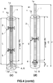
- Figure 4 illustrates various embodiments of a lance according to the present invention. It comprises an inner tube (1), which is hollow and made of metal, generally steel. It extends over a length, L, along a longitudinal direction, X1, from an inlet end (1u) to a tube end (1d), defining a fluid flow path from the tube inlet (1u) to a gas outlet (1t) located at or adjacent to the tube end (1d).
- gas outlet is used herein regardless of the nature of the fluid being injected therethrough, whether a fluid or solid particulate material (e.g., gas alone, a mixture of a gas or liquid with solid particles, or a mixture of gas and liquid droplets).
- the length, L can be of the order of several meters, typically 0.5 to 10 m, but more generally from 4 to 7 m, and even about 5 to 6 m long.
- the inner tube is generally albeit not necessarily cylindrical.
- the outlet (1t) can be coaxial with the longitudinal axis, X1, and may correspond to the tube end (1d), but often the outlet (1t) is composed of one or more smaller channels or tubes (6) extending, not necessarily parallel to X1, from -or adjacent to- said tube end (1d), as discussed e.g., in EP-A1-0802262 .
- the inner tube (1) is partially embedded in a refractory sheath (2) made of a refractory material surrounding the inner tube (1) from the tube end (1d) over a length, L1 ⁇ L, of the inner tube.
- the refractory sheath (2) protects the inner tube (1) from any contact with molten metal which would inevitably degrade the inner tube due to the high temperature of the molten metal. It acts as an insulating sleeve. Crack formation in the refractory sheath must be prevented as the formation of cracks is detrimental to the insulating function of the sheath. If a crack propagates as far as the inner tube, molten metal may penetrate and contact the inner tube, thus forming a thermal bridge and corresponding high temperature region in the inner tube, which would rapidly degrade the inner tube.
- a lance is usually held in substantially vertical operating position with holding means (22) (visible in Fig.1(a) ) gripping a portion of the inner tube jutting out of the refractory sheath.
- holding means (22) visible in Fig.1(a)
- the several meters long refractory sheath therefore hangs freely over a metallurgical vessel. It must therefore be secured to prevent the refractory sheath from slipping off the inner tube and falling into the molten metal.
- an anchoring point (4) is rigidly coupled to said inner tube at an anchor level, and is at least partially embedded in the refractory sheath, to prevent any movement of the inner tube at the anchor level relative to the refractory sheath in the longitudinal direction, X1.
- the anchoring level can be located anywhere along the embedded length of the inner tube, preferably near the tube end or near an upstream portion of the refractory sheath, wherein "upstream” and “downstream” are defined with respect of the fluid flow.
- the outlet (1t) does not correspond to the tube end (1d).
- the outlet (1t) is then provided at an end of one or more outlet tubes (6) coupled to and extending from the inner tube, through the refractory sheath to an outer surface of the refractory sheath and forming the gas outlet(s) (1t) bringing the inner bore of the inner tube in fluid communication with the exterior of the lance.
- the outlet tube(s) (6) are located at or adjacent to the tube end (1d).
- the expression "adjacent to the tube end” is meant here to mean within 10% of L1 from the tube end, and preferably not further than 50 cm, more preferably not further than 30 cm from the tube end (1d).
- outlet tubes (6) are transverse to the longitudinal axis, X1, and if they are mechanically strong enough, the outlet tubes can act as anchoring points (4) as illustrated in Figure 4(c) . Further examples of outlet tubes or channels which can be used in a lance of the present invention are depicted in EP-A1-0802262 .
- a single anchoring point (4) is preferred.
- Several anchoring points (4) can be used, as illustrated in Figure 4(b) , provided all anchoring points are distributed along the length of the inner tube surrounded by the refractory sheath, such that the coupling locations of the two anchoring points most remote from one another are preferably separated by a distance, L0, smaller than 5.5 10 -6 / ⁇ [m] (L0 ⁇ 5.5 10 -6 / ⁇ [m]), wherein ⁇ is the coefficient of thermal expansion of the inner tube (1).
- the distance, L0, between the two anchoring points most remote from one another measured in the direction of the longitudinal axis, X1, is preferably not greater than 0.5 m (L0 ⁇ 0.5 m).
- the refractory sheath can be safely secured to the inner tube and, at the same time, the thermally induced length variations of the anchoring level are negligible in comparison with the thermally induced length variations over the rest of the inner tube.
- the single anchoring point (4) or the one of several anchoring points located furthest from the inlet end (1u) is preferably coupled to the inner tube at a location at or adjacent to the tube end (1d).
- outlet tubes (6) act as anchoring points (4) discussed supra and illustrated in Figure 4(c) is an example of this embodiment.
- the single anchoring point (4) or the one of several anchoring points located closest to the inlet end (1u) can be located within 50 cm of the upstream end of the refractory sheath.
- the refractory sheath (2) is separated from the inner tube (1) by an annular gap (1g) extending over a length, Lg, which is at least 50% of L1.
- the maximum width of the annular gap (1g) is preferably comprised between 0.5 and 15 mm, more preferably between 1 and 10 mm and most preferably between 2 and 5 mm.
- the annular gap defined by an outer surface of the inner tube and an opposite inner surface of the refractory sheath allows said outer surface of the inner tube to move relative to said inner surface of the refractory sheath without generating substantial shear stresses.
- Lg is at least 60% of the length, L1, of inner tube embedded in (or surrounded by) the refractory sheath (Lg ⁇ 0.6 L1), preferably at least 75% of L1 (Lg ⁇ 3 ⁇ 4 L1).
- embedded is used herein to encompass both the case wherein the inner tube and refractory sheath contact each other forming an interface, and the case wherein they are separated by a gap (1g).
- the annular gap Before firing of the refractory sheath, the annular gap may be filled by a thermally degradable material or thermally removable material.
- This thermally degradable material or thermally removable material will be discussed more in details below with respect to the process for producing a lance according to the present invention. Suffices to say that the thermally degradable material or thermally removable material is removed from the annular gap by degradation, melting, vaporization, combustion or dissolution during firing of the refractory sheath, if it applies, or during use in a metallurgical installation (in some cases the refractory sheath is not fired).
- This geometry as such would, however, be unstable because in use the long portion of tube un-coupled to the refractory sheath (i.e., excluding the anchor level) would vibrate and hit the refractory wall defining the annular gap (1g), thus causing cracks in the refractory material.
- annular guide (5) surrounding the inner tube and located within the length, Lg, of the annular gap (1g).
- Figures 5 to 7 illustrate embodiments of such annular guides which comprise:
- the annular guide (5) is characterized in that said at least two anchor protrusions are distributed over the external surface of the annular portion (5A), separated from one another by an angle comprised between 90° and 270° measured from the centroid of the annular portion and between the contact points of the two anchor protrusions (5P) with the outer surface of the annular portion (5A) of the annular guide.
- a first and second protrusions (5P1, 5P3) can be separated by an angle smaller than 90° provided there is at least a third protrusion (5P2) which forms with the first protrusion (5P1) an angle comprised between 90 and 270°.
- the anchor protrusions (5P) also contribute to the reinforcement of the refractory material forming the sheath.
- at least three anchor protrusions per annular guide are preferred.
- the anchor protrusions can have different geometries, as long as they protrude out of the outer surface of the annular portion (5A) of the annular guide, and can thus be embedded in the refractory material of the sheath.
- the anchor protrusions (5P) generally comprise two portions transverse to each other, preferably defining a T-shape (cf. Figure 5 ), V-shape (cf. Figure 6(a) ), Y-shape (cf. Figure 6(b) ), X-shape (not shown), L-shaped (not shown), and the like.
- the distribution of the at least two anchor protrusions (5P) over the circumference of the outer surface of the annular portion of the annular guide ensures the stability of annular guide with respect to the parallelism of the annular portion (5A) with respect to the longitudinal axis, X1.
- the inner tube (1) can move freely through the annular portion (5A) and with respect to the refractory sheath at the level of said annular guide.
- the annular guide is provided with two anchor protrusions (5P) separated from one another by an angle comprised between 90 and 270° (cf. Figure 7(a) ), preferably comprised between 120 and 240°, more preferably by an angle of 180° (i.e., the two protrusions are diametrically opposed).
- the annular guide can be provided with three anchor protrusions as illustrated in Figures 5 and 7(a) . It can be provided with four anchor protrusions (5P) as illustrated in Figure 6 . More anchor protrusions may be used, but good results can already be obtained with 2 to 4 anchor protrusions per annular guide (5).
- N of anchor protrusions (5P)
- a distribution of the anchor protrusions (5P) around the perimeter of the annular portion of the annular guides as defined above gives the annular guides a great stability during use, ensuring that they remain substantial co-axial with the inner tube (1).
- a guide gap (5g) is provided between the inner tube and the annular portion (5A) of the annular guides (5).
- the guide gap (5g) must be present between at least 50% of the inner surface of the annular portion and an outer surface of the inner tube.
- the guide gap (5g) extends over the whole perimeter of the annular portion (5A) and inner tube (1).
- the guide gap (5g) ensures that the inner tube can move freely with respect to the annular guide along the longitudinal direction, X1, without generating substantial shear stresses in the refractory material.
- the maximum width of the guide gap (5g) is preferably smaller than the maximum width of the annular gap (1g).
- the maximum width of the guide gap (5g) is preferably comprised between 0.5 and 10 mm, more preferably between 1 and 5 mm.
- the annular portion of the annular guide (5) can form a closed loop.
- the annular portion of the annular guide (5) can form an open loop with a slit (5S) of width of not more than 40% of a perimeter of the annular portion (5A).
- An annular portion (5A) with a slit (5S) has the advantage that the diameter defined by the annular portion may be increased by opening further the width of the slit upon positioning the annular guides over the inner tube (1).
- Most inner tubes are cylindrical (or at least comprise cylindrical portions).
- the inner surface of the annular portion (5A) should define substantially the same cross-section as the inner tube, with dimensions increased to afford the guide gap (5g).
- the annular portion (5A) generally has a height measured along the direction of the longitudinal axis, X1, which is larger than a thickness measured in the radial direction.
- an annular portion can be comprised between 1.5 and 25 cm, preferably between 5 and 20 cm, more preferably between 7 and 15 cm.
- the inner surface of the annular portion (5A) is defined by a vector parallel to the longitudinal axis, X1, as illustrated in Figure 10(a) .
- the inner surface of the annular portion can be curved in the direction of the longitudinal axis, X1. This embodiment can help reducing the frictions between inner tube and annular guide in case the latter is misaligned with respect to the longitudinal axis, X1.
- the inner surface of the annular portion (5A) can be provided with at least two, preferably three (or more) centering elements (5C) illustrated in Figure 11 , protruding radially towards the center of the annular portion and distributed at regular intervals around the perimeter of the inner surface.
- the centering elements (5C) preferably have a curved surface. They may protrude out of the inner surface to a distance corresponding to the width of the annular gap (5g). This way, as illustrated in Figure 11(b) the annular guide maintains a finite number of punctual contacts with the inner tube (1) (three punctual contacts are shown in Figure 11(b) ). This has two advantages.
- the width of the annular gap (5g) can be controlled accurately and there is no risk of misalignment between the annular guide and the inner tube provoked (i.e., annular guides remain co-axial with the longitudinal axis, X1), for example, during casting of the refractory material into a casting mould around the inner tube provided with annular guides (cf. e.g., Figures 8(a) and 9(a) ).
- the inner tube (1) is prevented from vibrating with an amplitude equal to twice the width of the annular gap (5g), yielding a much more stable lance during injection operations.
- the inner tube is free to vary dimensions as a function of temperature with no hindrance from the annular guides.
- the centering elements (5C) are mounted on resilient means or are made of a resilient material to afford radial expansion of the inner tube.
- annular guide (5) located at a distance, preferably of at least L1 / 2, from the anchoring level, as illustrated in Figure 4(d) . It is, however, preferred that at least two annular guides (5) are distributed along the length, Lg, of the annular gap (1g), as illustrated in Figure 4(c) . More annular guides (5) yield higher stability of the inner tube over the length, Lg, wherein the portion of refractory sheath comprises the annular gap (1g).
- a lance according to the present invention can be produced by a process comprising the following steps, illustrated in Figure 8 :
- a sheet (15) of thermally degradable or a thermally removable sheet material between the inner surface of the annular portion of the annular guides (5) and the outer surface of the inner tube.
- the sheet (15) allows the centering of the annular portion with respect to the inner tube (1), co-axially with the longitudinal axis, X1.
- a guide gap (5g) of controlled and substantially constant width throughout the perimeter of the annular portion can thus be obtained.
- the outer surface of the annular portion (5A) and/or some portions of the anchor protrusions (5P) most prompt to create stresses in the surrounding refractory material due to thermal expansion can also be covered with a layer of thermally degradable or thermally removable sheet material (15).
- This process has the advantage that the width of the guide gap (5g) can be controlled independently of the width of the annular gap (1g). It is preferred that the guide gap (5g) be smaller than the annular gap (1g); so that the annular guides (5) restrict the radial movements of the inner tube but not the longitudinal movements. Another advantage of this process is that by resting on the upper edge of a tubular spacer, an annular guide (5) is maintained in good alignment with the longitudinal axis, X1, although the production process of the lance.
- the thermally degradable or thermally removable sheet material can be any material that is combusted at temperatures of the order of 600-1000°C. It may consist of paper or cardboard, a polymer sheet, and the like. The sheet material can also be melted or vaporized at such temperatures. For example a wax or low melting temperature thermoplastic material can be used, such as a polyolefin.
- the mechanically degradable material can be any brittle material that will lose mechanical coherence upon application of a shear stress, in particular provoked by the differing thermal variations between the inner tube (1) and the refractory sheath (2) upon exposure to temperature variations during use of the lance.
- a lance according to the present invention can be produced with the following steps:
- the thermally degradable or thermally removable sheet material (11W) is preferably compressible in thickness,
- a corrugated cardboard sheet material can be used or, alternatively a synthetic foam material.
- annular guides (5) with an open loop shaped annular portion, such that the slit (5S) can be increased by application of a circumferential stress when inserting the annular portion through the inner tube wrapped with the compressible sheet material (11W) to increase the breadth of the opening of the annular portion.
- the annular portion Upon releasing the stress, the annular portion returns to its nominal diameter which is smaller than the diameter of the inner tube wrapped with the sheet material (11W), such that the compressible sheet material is compressed by the annular portion (5A).
- a guide gap (5g) of width smaller than the width of the annular gap (1g) can thus be obtained.
- the refractory material after drying, the refractory material can be fired, All refractory materials do not require firing, but many do.
- the refractory material is sintered and at the same time, the thermally degradable material or thermally removable material of the tubular spacers (11.1, 11.2, 11.n) or of the sheet material (11W) is thermally degraded or removed and at least partially disappears from the outer surface of the inner tube, thus forming:
- the refractory cement is shown in Figures 8 &9 to be cast from the top into a casting mould (12) held vertically. This is indeed a preferred embodiment. It is, however, possible to cast the refractory material into a casting mould held horizontally as described in EP2712938 . As known in the art, the casting mould can be vibrated during casting and setting of the refractory material.
- a lance for injecting a fluid with or without a solid particulate material into a metallurgical vessel filled with molten metal has a substantially longer service life than henceforth achievable.
- the shear stresses mainly due to thermal dilatation mismatches between the metal inner tube and refractory sheath are avoided, thus maintaining the refractory material integrity for a longer time, which can thus protect the inner tube.
- Figure 12 illustrates a lance comprising a pusher (23) and a blocking element (24).
- the pusher (23) e.g. a steel plate which is maintained on the upper surface of the refractory sheath by resilient elements such as pre-stressed springs (25) set between the pusher (23) and the blocking element (24) e.g. a steel plate welded on the inner tube (1).
- the blocking element (24) shifts vertically with the inner tube.
Landscapes
- Engineering & Computer Science (AREA)
- Chemical & Material Sciences (AREA)
- Mechanical Engineering (AREA)
- General Engineering & Computer Science (AREA)
- Manufacturing & Machinery (AREA)
- Materials Engineering (AREA)
- Metallurgy (AREA)
- Organic Chemistry (AREA)
- Treatment Of Steel In Its Molten State (AREA)
- Furnace Charging Or Discharging (AREA)
Claims (15)
- Lanze für die Top-Injektion eines flüssigen oder partikelförmigen Materials in metallurgische Gefäße, wobei die Lanze besteht aus:(a) ein Innenrohr (1), das hohl und aus Metall besteht und sich über eine Länge, L, entlang einer Längsrichtung X1 von einem Einlassende (1u) zu einem Rohrende (1d) erstreckt und einen Fluidströmungsweg vom Rohreinlass (1u) zu einem Gasauslass (1t) definiert, der sich am oder angrenzend an das Rohrende (1d) befindet,(b) eine Hülle aus feuerfestem Material (2), die das Innenrohr (1) vom Rohrende über eine Länge, L1 ≤ L, der Innenröhre umgibt,(c) ein Verankerungspunkt (4), der starr mit dem Innenrohr in einer Ankerebene gekoppelt und zumindest teilweise in die feuerfeste Hülle eingebettet ist, wodurch eine Bewegung des Innenrohrs in der Ankerebene in Bezug auf die feuerfeste Hülle in Längsrichtung X1 verhindert wird,(d) einen Ringspalt (1g), der das Innenrohr von der feuerfesten Hülle über eine Länge, Lg, die mindestens 50% von L1 beträgt, trennt;(e) mindestens eine ringförmige Führung (5), die das Innenrohr umgibt und innerhalb der Länge Lg des Ringspalts (1g) angeordnet ist, wobei die ringförmige Führung umfasst:dadurch gekennzeichnet, dass die mindestens zwei Ankervorsprünge über die Außenfläche des ringförmigen Abschnitts (5A) verteilt sind, die durch einen Winkel zwischen 90° und 270°, gemessen vom Schwerpunkt des ringförmigen Abschnitts, und zwischen den Kontaktpunkten der beiden Ankervorsprünge (5P) mit der Außenfläche des ringförmigen Abschnitts (5A) der ringförmigen Führung voneinander getrennt sind, mit der Maßgabe dass, wenn die Lanze mehrere Verankerungspunkte umfasst, die entlang der Länge des von der feuerfesten Ummantelung umgebenen Innenrohrs verteilt sind, die Kopplungspositionen zum Innenrohr der beiden in Längsrichtung X1 am weitesten voneinander entfernten Verankerungspunkte durch einen Abstand L0 getrennt sind, wobei L0 ≤ 5.5 10-6 / α [m], wobei α der Wärmeausdehnungskoeffizient des Innenrohres (1) ist, und wobei der Abstand L0 auf jeden Fall nicht größer als 50 cm ist.- einen ringförmigen Abschnitt (5A) mit einer Innenfläche und einer Außenfläche, wobei die Innenfläche dem Innenrohr zugewandt ist und dieses umschließt, und- mindestens zwei Ankervorsprünge (5P), die sich starr quer zur Außenfläche des Ringabschnitts erstrecken und zumindest teilweise in die feuerfeste Hülle (2) eingebettet sind,wobei ein Führungsspalt (5g) zwischen mindestens 50% der Innenfläche des Ringabschnitts und einer Außenfläche des Innenrohrs gebildet ist, der die Bewegung des Innenrohrs in Bezug auf die Ringführung entlang der Längsrichtung X1 ermöglicht
- Lanze nach Anspruch 1, wobei thermisch abbaubares Material, mechanisch abnehmbares Material und/or thermisch herausnehmbares Material im Ringspalt (1g) vorhanden ist.
- Lanze nach Anspruch 1 oder 2, wobei die maximale Breite des Ringspaltes (1g) zwischen 0,5 und 15 mm, vorzugsweise zwischen 1 und 10 mm und stärker bevorzugt zwischen 2 und 5 mm liegt.
- Lanze nach einem der obigen Ansprüche, wobei die maximale Breite des Führungsspalts (5g) kleiner als die maximale Breite des Ringspalts (1g) ist und vorzugsweise zwischen 0,5 und 10 mm, stärker bevorzugt zwischen 1 und 5 mm liegt.
- Lanze nach einem der obigen Ansprüche, wobei der ringförmige Abschnitt der ringförmigen Führung (5) einen geschlossenen Kreislauf bildet oder alternativ, wobei der ringförmige Abschnitt der ringförmigen Führung (5) einen offenen Kreislauf mit einem Schlitz (5S) mit einer Breite von nicht mehr als 40% eines inneren Umfangs des ringförmigen Abschnitts bildet.
- Lanze nach einem der obigen Ansprüche, wobei ein Auslassabschnitt des Innenrohrs, der an das Rohrende angrenzt und dieses einschließt, mit einem oder mehreren Auslassrohren (6) gekoppelt ist, die sich vom Innenrohr durch die feuerfeste Hülle zu dem/den Gasauslass(en) (1t) erstrecken, bringen einer Innenbohrung des Innenrohres in fließender Verbindung mit der Außenseite der Lanze.
- Lanze nach einem der obigen Ansprüche, bestehend aus einem einzigen Verankerungspunkt (4), der mit dem Innenrohr gekoppelt ist.
- Lanze nach Anspruch 7, wobei der einzelne Verankerungspunkt (4) oder einer von mehreren Verankerungspunkten, die am weitesten vom Einlassende (1u) entfernt sind, mit dem Innenrohr an einer Stelle am oder neben dem Rohrende (1d) gekoppelt ist.
- Lanze nach einem der obigen Ansprüche, worin die Ankervorsprünge (5P) zwei Abschnitte quer zueinander umfassen, die vorzugsweise eine T-Form, V-Form, X-Form oder Y-Form definieren.
- Lanze nach einem der obigen Ansprüche, wobei die Außenfläche des ringförmigen Abschnitts (5A) und/oder einige Abschnitte der Ankervorsprünge (5P) zumindest teilweise mit einer Schicht aus thermisch abbaubarem oder thermisch entfernbarem Blattmaterial (15) bedeckt sind.
- Verfahren zur Herstellung einer Lanze nach einem der Ansprüche 1 bis 10, bestehend aus folgende Schritte:(a) Bereitstellen eines Innenrohrs (1) der Länge L, das durch eine Außenfläche definiert ist und ein Rohrende (1d) und einen Verankerungspunkt (4), der fest mit der Außenfläche verbunden ist in einem Abstand La vom Rohrende (1d) mit La ≤ L, enthalt;(b) Einsetzen eines ersten rohrförmigen Abstandhalters (11.1) aus einem thermisch abbaubaren Material, einem mechanisch abnehmbaren Material und/oder einem thermisch herausnehmbaren Material über das Innenrohr (1);(c) Einsetzen einer ringförmigen Führung (5) mit mindestens zwei Verankerungsvorsprüngen über das Innenrohr, bis diese auf einer Kante des ersten rohrförmigen Abstandshalters (11.1) aufliegt.(d) Wiederholen der Schritte (b) und (c), bis die gewünschte Anzahl von Ringführungen erreicht ist und bis die kumulierte Länge von Rohrabstandshaltern und Ringführungen gleich oder größer als die gewünschte Länge Lg des Ringspaltes (1g) ist;(e) Bereitstellen einer Gießform mit einer Länge größer oder gleich L1(f) Positionieren des so gebildeten Innenrohres in besagte Form mit dem Rohrende innerhalb der Form,(g) Gießen eines feuerfesten Materials in die Form, das das so gebildete Innenrohr und mindestens einen Teil der Verankerungsvorsprünge (5P) der ringförmigen Führungen einbettet und so eine Hülle aus feuerfestem Material der Länge L1 bildet, wobei Lg ≥ ½ L1;(h) Das Feuerfestmaterial zumindest teilweise trocknen.
- Verfahren zur Herstellung einer Lanze nach einem der Ansprüche 1 bis 10, umfassend die folgenden Schritte:(a) Bereitstellen eines Innenrohrs (1) der Länge L, das durch eine Außenfläche definiert ist und ein Austrittsende (1d) und einen Verankerungspunkt (4) umfasst, der starr mit der Außenfläche gekoppelt ist und in einem Abstand L1 vom Austrittsende (1d) angeordnet ist, mit L1 ≤ L;(b) Umwickeln der Außenfläche des Innenrohrs (1) mit einem thermisch abbaubaren, mechanisch abnehmbaren Material und/oder thermisch herausnehmbaren Blattmaterial (11W) vorgegebener Dicke über eine Länge Lg, gleich mindestens 50% des Abstands L1;(c) Einsetzen von beliebig vielen Ringführungen (5) über das mit Blatt ummantelte Innenrohr (1), die in einem vorgegebenen Abstand voneinander angeordnet sind;(d) Bereitstellen einer Gießform mit einer Länge größer oder gleich L1(e) Positionieren des so gewickelten Innenrohres in die Form mit dem Austrittsende innerhalb der Form,(f) Gießen des feuerfesten Materials in die Form, wobei das so gebildete Innenrohr und mindestens ein Teil der Verankerungsvorsprünge (5P) der Ringführungen eingebettet sind, wodurch eine Hülle aus feuerfestem Material der Länge L1 gebildet wird;(g) Das Feuerfestmaterial zumindest teilweise trocknen.
- Verfahren nach Anspruch 11 oder 12, bei dem das thermisch abbaubare Material oder thermisch entfernbare Material der rohrförmigen Abstandhalter (11.1, 11.2, 11.n) oder des Blattmaterials (11W) thermisch abgebaut oder entfernt wird und zumindest teilweise von der Außenfläche des Innenrohres beim Zünden der Lanze oder beim Eintauchen der Lanze in ein metallurgisches Gefäß verschwindet, so dass:• zwischen dem Innenrohr und der feuerfesten Hülle wird ein Ringspalt (1g) über eine Länge Lg von mindestens 50% der Länge L1 der feuerfesten Hülle gebildet, der die Bewegung eines Teils des Innenrohrs der vom Verankerungspunkt (4) entfernt ist, entlang der Längsrichtung X1, in Bezug auf die feuerfeste Hülle ermöglicht, und• ein Führungsspalt (5g) ist über mindestens 50% eines Umfangs der Innenfläche der ringförmigen Führungen ausgebildet, der die Bewegung des Innenrohres in Bezug auf die ringförmigen Führungen entlang der Längsrichtung X1 ermöglicht.
- Verfahren nach einem der Ansprüche 12 bis 14, ferner umfassend das Aufbringen von thermisch abbaubarem oder thermisch herausnehmbaren Blattmaterial (15) auf mindestens einen Teil der mindestens zwei Ankervorsprünge (5P) und/oder die Außenfläche des ringförmigen Teils (5A) der ringförmigen Führungen.
- Lanze nach einem der Ansprüche 1 bis 10, ferner umfassend einen Schieber (23) und ein Blockierelement (24), wobei das Blockierelement (24) starr mit dem Innenrohr (1) in einem Abschnitt des Innenrohrs in einem Abstand von der Ankerebene größer als L1 gekoppelt ist und der Schieber (23) elastisch mit dem Blockierelement (24) verbunden ist, wobei der Schieber geeignet ist, die feuerfeste Hülle entlang der Richtung der Längsachse X1 zu drücken.
Applications Claiming Priority (3)
| Application Number | Priority Date | Filing Date | Title |
|---|---|---|---|
| EP15163822 | 2015-04-16 | ||
| EP15202638 | 2015-12-23 | ||
| PCT/EP2016/058179 WO2016166189A1 (en) | 2015-04-16 | 2016-04-14 | Lance for top injection in metallurgical vessels and process for manufacturing same |
Publications (2)
| Publication Number | Publication Date |
|---|---|
| EP3283659A1 EP3283659A1 (de) | 2018-02-21 |
| EP3283659B1 true EP3283659B1 (de) | 2019-06-12 |
Family
ID=55808562
Family Applications (1)
| Application Number | Title | Priority Date | Filing Date |
|---|---|---|---|
| EP16718290.6A Active EP3283659B1 (de) | 2015-04-16 | 2016-04-14 | Lanze zum eintauchen in metallurgische gefässe und verfahren zur herstellung davon |
Country Status (9)
| Country | Link |
|---|---|
| US (1) | US20180087121A1 (de) |
| EP (1) | EP3283659B1 (de) |
| KR (1) | KR20170137120A (de) |
| AU (1) | AU2016247384A1 (de) |
| BR (1) | BR112017022099A2 (de) |
| CA (1) | CA2981973A1 (de) |
| EA (1) | EA201791889A1 (de) |
| WO (1) | WO2016166189A1 (de) |
| ZA (1) | ZA201706578B (de) |
Families Citing this family (2)
| Publication number | Priority date | Publication date | Assignee | Title |
|---|---|---|---|---|
| EP3922736A1 (de) | 2020-06-08 | 2021-12-15 | ImerTech SAS | Blaslanze zum gaseinblasen, ihre verwendung und verfahren zur herstellung |
| WO2025076045A1 (en) * | 2023-10-02 | 2025-04-10 | Pyrotek, Inc. | Scrap submergence device |
Family Cites Families (8)
| Publication number | Priority date | Publication date | Assignee | Title |
|---|---|---|---|---|
| GB1431123A (en) * | 1973-08-22 | 1976-04-07 | Stein Refractories | Metallurgical lances |
| GB2107034A (en) | 1981-09-30 | 1983-04-20 | Steetley Refractories Ltd | Lance |
| US4852860A (en) * | 1987-08-24 | 1989-08-01 | Bethlehem Steel Corporation | Consumable injection lance |
| KR100227066B1 (ko) | 1995-01-06 | 1999-10-15 | 아사무라 타카싯 | 탈탄 특성이 뛰어난 전로 상취 정련 방법 및 전로용 상취 랜스 |
| DE29705901U1 (de) | 1997-04-03 | 1997-05-28 | Funke, Dennis, 47627 Kevelaer | Mit Argon gekühlte Spüllanze |
| CA2541906C (en) * | 2003-10-21 | 2013-01-08 | Outokumpu Technology Oy | A pipe segment for a transfer line for transporting hot particulate material |
| US20050110202A1 (en) * | 2003-11-21 | 2005-05-26 | North American Refractories Co. | Injection lance |
| BRPI1102228A2 (pt) | 2011-05-17 | 2013-06-25 | Magnesita Refratarios S A | lanca para injecao de topo em vasos metalurgicos e metodo para fabricacao dessa lanca |
-
2016
- 2016-04-14 AU AU2016247384A patent/AU2016247384A1/en not_active Abandoned
- 2016-04-14 EA EA201791889A patent/EA201791889A1/ru unknown
- 2016-04-14 KR KR1020177030472A patent/KR20170137120A/ko not_active Withdrawn
- 2016-04-14 BR BR112017022099A patent/BR112017022099A2/pt not_active Application Discontinuation
- 2016-04-14 WO PCT/EP2016/058179 patent/WO2016166189A1/en not_active Ceased
- 2016-04-14 EP EP16718290.6A patent/EP3283659B1/de active Active
- 2016-04-14 US US15/566,424 patent/US20180087121A1/en not_active Abandoned
- 2016-04-14 CA CA2981973A patent/CA2981973A1/en not_active Abandoned
-
2017
- 2017-09-29 ZA ZA2017/06578A patent/ZA201706578B/en unknown
Non-Patent Citations (1)
| Title |
|---|
| None * |
Also Published As
| Publication number | Publication date |
|---|---|
| CA2981973A1 (en) | 2016-10-20 |
| US20180087121A1 (en) | 2018-03-29 |
| WO2016166189A1 (en) | 2016-10-20 |
| BR112017022099A2 (pt) | 2018-07-03 |
| EA201791889A1 (ru) | 2018-03-30 |
| EP3283659A1 (de) | 2018-02-21 |
| ZA201706578B (en) | 2019-01-30 |
| KR20170137120A (ko) | 2017-12-12 |
| AU2016247384A1 (en) | 2017-10-12 |
Similar Documents
| Publication | Publication Date | Title |
|---|---|---|
| KR101270881B1 (ko) | 용융 금속욕의 온도를 측정하는 방법 및 장치 | |
| US4367868A (en) | Refractory lining for a metal pipe | |
| US3279003A (en) | Composite pouring tube | |
| EP3346030B1 (de) | Anlage für die herstellung eines teils durch umsetzung eines bridgman-verfahrens | |
| US20180087121A1 (en) | Lance for top injection in metallurgical vessels and process for manufacturing same | |
| US10232435B2 (en) | Refractory ceramic casting nozzle | |
| KR101244320B1 (ko) | 온도 측정 장치 및 이를 이용한 온도 측정 방법 | |
| US20140300036A1 (en) | Refractory purging devices | |
| US20090314450A1 (en) | Method and apparatus for casting metal articles | |
| US3456690A (en) | Composite sleeve for ladle stopper rods | |
| US1335685A (en) | Ingot-mold | |
| GB2227437A (en) | Heated casting tube | |
| CN115698341A (zh) | 用于气体喷吹的鼓风喷枪、其用途和生产方法 | |
| JP5630301B2 (ja) | 単結晶製造装置及び単結晶製造方法 | |
| KR100358029B1 (ko) | 열 차폐 부재 및 이를 이용한 실리콘 단결정 인상 장치 | |
| JP6881403B2 (ja) | 支持材、耐火物構造体及び耐火物構造体の製造方法 | |
| CN112512725A (zh) | 尤其在立式铸造设备中用于铸钢的连铸方法 | |
| GB2114721A (en) | Injection lances for molten metal | |
| JP2019123897A (ja) | 羽口ユニットおよびその設置方法 | |
| JPS5837940Y2 (ja) | 上吹用ランスパイプ | |
| JPH06117771A (ja) | 耐火物ライニング及びその解体方法 | |
| US1208703A (en) | Feeder for standard ingot-molds. | |
| JP2002224797A (ja) | 溶融金属の下注ぎ造塊装置 | |
| JP2633399B2 (ja) | 水平連続鋳造設備用タンディッシュ | |
| FR3075671B1 (fr) | Creuset pour la solidification dirigee d'un lingot |
Legal Events
| Date | Code | Title | Description |
|---|---|---|---|
| STAA | Information on the status of an ep patent application or granted ep patent |
Free format text: STATUS: THE INTERNATIONAL PUBLICATION HAS BEEN MADE |
|
| PUAI | Public reference made under article 153(3) epc to a published international application that has entered the european phase |
Free format text: ORIGINAL CODE: 0009012 |
|
| STAA | Information on the status of an ep patent application or granted ep patent |
Free format text: STATUS: REQUEST FOR EXAMINATION WAS MADE |
|
| 17P | Request for examination filed |
Effective date: 20171116 |
|
| AK | Designated contracting states |
Kind code of ref document: A1 Designated state(s): AL AT BE BG CH CY CZ DE DK EE ES FI FR GB GR HR HU IE IS IT LI LT LU LV MC MK MT NL NO PL PT RO RS SE SI SK SM TR |
|
| AX | Request for extension of the european patent |
Extension state: BA ME |
|
| RAP1 | Party data changed (applicant data changed or rights of an application transferred) |
Owner name: VESUVIUS U S A CORPORATION |
|
| DAV | Request for validation of the european patent (deleted) | ||
| DAX | Request for extension of the european patent (deleted) | ||
| GRAP | Despatch of communication of intention to grant a patent |
Free format text: ORIGINAL CODE: EPIDOSNIGR1 |
|
| STAA | Information on the status of an ep patent application or granted ep patent |
Free format text: STATUS: GRANT OF PATENT IS INTENDED |
|
| INTG | Intention to grant announced |
Effective date: 20181129 |
|
| RIN1 | Information on inventor provided before grant (corrected) |
Inventor name: KREIERHOFF, MARTIN Inventor name: WARMERS, CHRISTIAN |
|
| GRAS | Grant fee paid |
Free format text: ORIGINAL CODE: EPIDOSNIGR3 |
|
| GRAA | (expected) grant |
Free format text: ORIGINAL CODE: 0009210 |
|
| STAA | Information on the status of an ep patent application or granted ep patent |
Free format text: STATUS: THE PATENT HAS BEEN GRANTED |
|
| AK | Designated contracting states |
Kind code of ref document: B1 Designated state(s): AL AT BE BG CH CY CZ DE DK EE ES FI FR GB GR HR HU IE IS IT LI LT LU LV MC MK MT NL NO PL PT RO RS SE SI SK SM TR |
|
| REG | Reference to a national code |
Ref country code: GB Ref legal event code: FG4D |
|
| REG | Reference to a national code |
Ref country code: CH Ref legal event code: EP |
|
| REG | Reference to a national code |
Ref country code: AT Ref legal event code: REF Ref document number: 1142610 Country of ref document: AT Kind code of ref document: T Effective date: 20190615 |
|
| REG | Reference to a national code |
Ref country code: DE Ref legal event code: R096 Ref document number: 602016015181 Country of ref document: DE |
|
| REG | Reference to a national code |
Ref country code: IE Ref legal event code: FG4D |
|
| REG | Reference to a national code |
Ref country code: NL Ref legal event code: MP Effective date: 20190612 |
|
| REG | Reference to a national code |
Ref country code: LT Ref legal event code: MG4D |
|
| PG25 | Lapsed in a contracting state [announced via postgrant information from national office to epo] |
Ref country code: NO Free format text: LAPSE BECAUSE OF FAILURE TO SUBMIT A TRANSLATION OF THE DESCRIPTION OR TO PAY THE FEE WITHIN THE PRESCRIBED TIME-LIMIT Effective date: 20190912 Ref country code: FI Free format text: LAPSE BECAUSE OF FAILURE TO SUBMIT A TRANSLATION OF THE DESCRIPTION OR TO PAY THE FEE WITHIN THE PRESCRIBED TIME-LIMIT Effective date: 20190612 Ref country code: HR Free format text: LAPSE BECAUSE OF FAILURE TO SUBMIT A TRANSLATION OF THE DESCRIPTION OR TO PAY THE FEE WITHIN THE PRESCRIBED TIME-LIMIT Effective date: 20190612 Ref country code: SE Free format text: LAPSE BECAUSE OF FAILURE TO SUBMIT A TRANSLATION OF THE DESCRIPTION OR TO PAY THE FEE WITHIN THE PRESCRIBED TIME-LIMIT Effective date: 20190612 Ref country code: AL Free format text: LAPSE BECAUSE OF FAILURE TO SUBMIT A TRANSLATION OF THE DESCRIPTION OR TO PAY THE FEE WITHIN THE PRESCRIBED TIME-LIMIT Effective date: 20190612 Ref country code: LT Free format text: LAPSE BECAUSE OF FAILURE TO SUBMIT A TRANSLATION OF THE DESCRIPTION OR TO PAY THE FEE WITHIN THE PRESCRIBED TIME-LIMIT Effective date: 20190612 |
|
| PG25 | Lapsed in a contracting state [announced via postgrant information from national office to epo] |
Ref country code: BG Free format text: LAPSE BECAUSE OF FAILURE TO SUBMIT A TRANSLATION OF THE DESCRIPTION OR TO PAY THE FEE WITHIN THE PRESCRIBED TIME-LIMIT Effective date: 20190912 Ref country code: RS Free format text: LAPSE BECAUSE OF FAILURE TO SUBMIT A TRANSLATION OF THE DESCRIPTION OR TO PAY THE FEE WITHIN THE PRESCRIBED TIME-LIMIT Effective date: 20190612 Ref country code: GR Free format text: LAPSE BECAUSE OF FAILURE TO SUBMIT A TRANSLATION OF THE DESCRIPTION OR TO PAY THE FEE WITHIN THE PRESCRIBED TIME-LIMIT Effective date: 20190913 Ref country code: LV Free format text: LAPSE BECAUSE OF FAILURE TO SUBMIT A TRANSLATION OF THE DESCRIPTION OR TO PAY THE FEE WITHIN THE PRESCRIBED TIME-LIMIT Effective date: 20190612 |
|
| REG | Reference to a national code |
Ref country code: AT Ref legal event code: MK05 Ref document number: 1142610 Country of ref document: AT Kind code of ref document: T Effective date: 20190612 |
|
| PG25 | Lapsed in a contracting state [announced via postgrant information from national office to epo] |
Ref country code: SK Free format text: LAPSE BECAUSE OF FAILURE TO SUBMIT A TRANSLATION OF THE DESCRIPTION OR TO PAY THE FEE WITHIN THE PRESCRIBED TIME-LIMIT Effective date: 20190612 Ref country code: RO Free format text: LAPSE BECAUSE OF FAILURE TO SUBMIT A TRANSLATION OF THE DESCRIPTION OR TO PAY THE FEE WITHIN THE PRESCRIBED TIME-LIMIT Effective date: 20190612 Ref country code: EE Free format text: LAPSE BECAUSE OF FAILURE TO SUBMIT A TRANSLATION OF THE DESCRIPTION OR TO PAY THE FEE WITHIN THE PRESCRIBED TIME-LIMIT Effective date: 20190612 Ref country code: AT Free format text: LAPSE BECAUSE OF FAILURE TO SUBMIT A TRANSLATION OF THE DESCRIPTION OR TO PAY THE FEE WITHIN THE PRESCRIBED TIME-LIMIT Effective date: 20190612 Ref country code: NL Free format text: LAPSE BECAUSE OF FAILURE TO SUBMIT A TRANSLATION OF THE DESCRIPTION OR TO PAY THE FEE WITHIN THE PRESCRIBED TIME-LIMIT Effective date: 20190612 Ref country code: CZ Free format text: LAPSE BECAUSE OF FAILURE TO SUBMIT A TRANSLATION OF THE DESCRIPTION OR TO PAY THE FEE WITHIN THE PRESCRIBED TIME-LIMIT Effective date: 20190612 Ref country code: PT Free format text: LAPSE BECAUSE OF FAILURE TO SUBMIT A TRANSLATION OF THE DESCRIPTION OR TO PAY THE FEE WITHIN THE PRESCRIBED TIME-LIMIT Effective date: 20191014 |
|
| PG25 | Lapsed in a contracting state [announced via postgrant information from national office to epo] |
Ref country code: SM Free format text: LAPSE BECAUSE OF FAILURE TO SUBMIT A TRANSLATION OF THE DESCRIPTION OR TO PAY THE FEE WITHIN THE PRESCRIBED TIME-LIMIT Effective date: 20190612 Ref country code: IT Free format text: LAPSE BECAUSE OF FAILURE TO SUBMIT A TRANSLATION OF THE DESCRIPTION OR TO PAY THE FEE WITHIN THE PRESCRIBED TIME-LIMIT Effective date: 20190612 Ref country code: ES Free format text: LAPSE BECAUSE OF FAILURE TO SUBMIT A TRANSLATION OF THE DESCRIPTION OR TO PAY THE FEE WITHIN THE PRESCRIBED TIME-LIMIT Effective date: 20190612 Ref country code: IS Free format text: LAPSE BECAUSE OF FAILURE TO SUBMIT A TRANSLATION OF THE DESCRIPTION OR TO PAY THE FEE WITHIN THE PRESCRIBED TIME-LIMIT Effective date: 20191012 |
|
| REG | Reference to a national code |
Ref country code: DE Ref legal event code: R097 Ref document number: 602016015181 Country of ref document: DE |
|
| PG25 | Lapsed in a contracting state [announced via postgrant information from national office to epo] |
Ref country code: TR Free format text: LAPSE BECAUSE OF FAILURE TO SUBMIT A TRANSLATION OF THE DESCRIPTION OR TO PAY THE FEE WITHIN THE PRESCRIBED TIME-LIMIT Effective date: 20190612 |
|
| PLBE | No opposition filed within time limit |
Free format text: ORIGINAL CODE: 0009261 |
|
| STAA | Information on the status of an ep patent application or granted ep patent |
Free format text: STATUS: NO OPPOSITION FILED WITHIN TIME LIMIT |
|
| PG25 | Lapsed in a contracting state [announced via postgrant information from national office to epo] |
Ref country code: PL Free format text: LAPSE BECAUSE OF FAILURE TO SUBMIT A TRANSLATION OF THE DESCRIPTION OR TO PAY THE FEE WITHIN THE PRESCRIBED TIME-LIMIT Effective date: 20190612 Ref country code: DK Free format text: LAPSE BECAUSE OF FAILURE TO SUBMIT A TRANSLATION OF THE DESCRIPTION OR TO PAY THE FEE WITHIN THE PRESCRIBED TIME-LIMIT Effective date: 20190612 |
|
| 26N | No opposition filed |
Effective date: 20200313 |
|
| PG25 | Lapsed in a contracting state [announced via postgrant information from national office to epo] |
Ref country code: SI Free format text: LAPSE BECAUSE OF FAILURE TO SUBMIT A TRANSLATION OF THE DESCRIPTION OR TO PAY THE FEE WITHIN THE PRESCRIBED TIME-LIMIT Effective date: 20190612 Ref country code: IS Free format text: LAPSE BECAUSE OF FAILURE TO SUBMIT A TRANSLATION OF THE DESCRIPTION OR TO PAY THE FEE WITHIN THE PRESCRIBED TIME-LIMIT Effective date: 20200224 |
|
| PG2D | Information on lapse in contracting state deleted |
Ref country code: IS |
|
| REG | Reference to a national code |
Ref country code: DE Ref legal event code: R119 Ref document number: 602016015181 Country of ref document: DE |
|
| PG25 | Lapsed in a contracting state [announced via postgrant information from national office to epo] |
Ref country code: MC Free format text: LAPSE BECAUSE OF FAILURE TO SUBMIT A TRANSLATION OF THE DESCRIPTION OR TO PAY THE FEE WITHIN THE PRESCRIBED TIME-LIMIT Effective date: 20190612 |
|
| REG | Reference to a national code |
Ref country code: CH Ref legal event code: PL |
|
| PG25 | Lapsed in a contracting state [announced via postgrant information from national office to epo] |
Ref country code: CH Free format text: LAPSE BECAUSE OF NON-PAYMENT OF DUE FEES Effective date: 20200430 Ref country code: DE Free format text: LAPSE BECAUSE OF NON-PAYMENT OF DUE FEES Effective date: 20201103 Ref country code: LI Free format text: LAPSE BECAUSE OF NON-PAYMENT OF DUE FEES Effective date: 20200430 Ref country code: FR Free format text: LAPSE BECAUSE OF NON-PAYMENT OF DUE FEES Effective date: 20200430 Ref country code: LU Free format text: LAPSE BECAUSE OF NON-PAYMENT OF DUE FEES Effective date: 20200414 |
|
| REG | Reference to a national code |
Ref country code: BE Ref legal event code: MM Effective date: 20200430 |
|
| PG25 | Lapsed in a contracting state [announced via postgrant information from national office to epo] |
Ref country code: BE Free format text: LAPSE BECAUSE OF NON-PAYMENT OF DUE FEES Effective date: 20200430 |
|
| GBPC | Gb: european patent ceased through non-payment of renewal fee |
Effective date: 20200414 |
|
| PG25 | Lapsed in a contracting state [announced via postgrant information from national office to epo] |
Ref country code: IE Free format text: LAPSE BECAUSE OF NON-PAYMENT OF DUE FEES Effective date: 20200414 Ref country code: GB Free format text: LAPSE BECAUSE OF NON-PAYMENT OF DUE FEES Effective date: 20200414 |
|
| PG25 | Lapsed in a contracting state [announced via postgrant information from national office to epo] |
Ref country code: MT Free format text: LAPSE BECAUSE OF FAILURE TO SUBMIT A TRANSLATION OF THE DESCRIPTION OR TO PAY THE FEE WITHIN THE PRESCRIBED TIME-LIMIT Effective date: 20190612 Ref country code: CY Free format text: LAPSE BECAUSE OF FAILURE TO SUBMIT A TRANSLATION OF THE DESCRIPTION OR TO PAY THE FEE WITHIN THE PRESCRIBED TIME-LIMIT Effective date: 20190612 |
|
| PG25 | Lapsed in a contracting state [announced via postgrant information from national office to epo] |
Ref country code: MK Free format text: LAPSE BECAUSE OF FAILURE TO SUBMIT A TRANSLATION OF THE DESCRIPTION OR TO PAY THE FEE WITHIN THE PRESCRIBED TIME-LIMIT Effective date: 20190612 |