EP3283349B1 - Système et procédé de direction pour véhicules autonomes - Google Patents
Système et procédé de direction pour véhicules autonomes Download PDFInfo
- Publication number
- EP3283349B1 EP3283349B1 EP16780478.0A EP16780478A EP3283349B1 EP 3283349 B1 EP3283349 B1 EP 3283349B1 EP 16780478 A EP16780478 A EP 16780478A EP 3283349 B1 EP3283349 B1 EP 3283349B1
- Authority
- EP
- European Patent Office
- Prior art keywords
- steering
- steering mechanism
- actuator
- autonomous
- torque
- Prior art date
- Legal status (The legal status is an assumption and is not a legal conclusion. Google has not performed a legal analysis and makes no representation as to the accuracy of the status listed.)
- Active
Links
- 238000000034 method Methods 0.000 title claims description 25
- 230000007246 mechanism Effects 0.000 claims description 83
- 230000008878 coupling Effects 0.000 claims description 60
- 238000010168 coupling process Methods 0.000 claims description 60
- 238000005859 coupling reaction Methods 0.000 claims description 60
- 230000001939 inductive effect Effects 0.000 claims description 6
- 230000008569 process Effects 0.000 claims description 6
- 239000012530 fluid Substances 0.000 claims description 4
- 230000003466 anti-cipated effect Effects 0.000 description 3
- 238000002485 combustion reaction Methods 0.000 description 2
- 230000003213 activating effect Effects 0.000 description 1
- 238000004891 communication Methods 0.000 description 1
- 230000000295 complement effect Effects 0.000 description 1
- 238000006073 displacement reaction Methods 0.000 description 1
- 230000005611 electricity Effects 0.000 description 1
- 239000000446 fuel Substances 0.000 description 1
- 238000012544 monitoring process Methods 0.000 description 1
- 230000004044 response Effects 0.000 description 1
- 230000007704 transition Effects 0.000 description 1
- 230000000007 visual effect Effects 0.000 description 1
Images


Classifications
-
- B—PERFORMING OPERATIONS; TRANSPORTING
- B62—LAND VEHICLES FOR TRAVELLING OTHERWISE THAN ON RAILS
- B62D—MOTOR VEHICLES; TRAILERS
- B62D15/00—Steering not otherwise provided for
- B62D15/02—Steering position indicators ; Steering position determination; Steering aids
- B62D15/025—Active steering aids, e.g. helping the driver by actively influencing the steering system after environment evaluation
-
- B—PERFORMING OPERATIONS; TRANSPORTING
- B62—LAND VEHICLES FOR TRAVELLING OTHERWISE THAN ON RAILS
- B62D—MOTOR VEHICLES; TRAILERS
- B62D3/00—Steering gears
- B62D3/02—Steering gears mechanical
- B62D3/12—Steering gears mechanical of rack-and-pinion type
-
- B—PERFORMING OPERATIONS; TRANSPORTING
- B62—LAND VEHICLES FOR TRAVELLING OTHERWISE THAN ON RAILS
- B62D—MOTOR VEHICLES; TRAILERS
- B62D5/00—Power-assisted or power-driven steering
- B62D5/04—Power-assisted or power-driven steering electrical, e.g. using an electric servo-motor connected to, or forming part of, the steering gear
- B62D5/0421—Electric motor acting on or near steering gear
-
- B—PERFORMING OPERATIONS; TRANSPORTING
- B62—LAND VEHICLES FOR TRAVELLING OTHERWISE THAN ON RAILS
- B62D—MOTOR VEHICLES; TRAILERS
- B62D5/00—Power-assisted or power-driven steering
- B62D5/04—Power-assisted or power-driven steering electrical, e.g. using an electric servo-motor connected to, or forming part of, the steering gear
- B62D5/043—Power-assisted or power-driven steering electrical, e.g. using an electric servo-motor connected to, or forming part of, the steering gear characterised by clutch means between driving element, e.g. motor, and driven element, e.g. steering column or steering gear
-
- B—PERFORMING OPERATIONS; TRANSPORTING
- B62—LAND VEHICLES FOR TRAVELLING OTHERWISE THAN ON RAILS
- B62D—MOTOR VEHICLES; TRAILERS
- B62D5/00—Power-assisted or power-driven steering
- B62D5/04—Power-assisted or power-driven steering electrical, e.g. using an electric servo-motor connected to, or forming part of, the steering gear
- B62D5/0457—Power-assisted or power-driven steering electrical, e.g. using an electric servo-motor connected to, or forming part of, the steering gear characterised by control features of the drive means as such
- B62D5/046—Controlling the motor
- B62D5/0463—Controlling the motor calculating assisting torque from the motor based on driver input
-
- B—PERFORMING OPERATIONS; TRANSPORTING
- B62—LAND VEHICLES FOR TRAVELLING OTHERWISE THAN ON RAILS
- B62D—MOTOR VEHICLES; TRAILERS
- B62D5/00—Power-assisted or power-driven steering
- B62D5/04—Power-assisted or power-driven steering electrical, e.g. using an electric servo-motor connected to, or forming part of, the steering gear
- B62D5/0457—Power-assisted or power-driven steering electrical, e.g. using an electric servo-motor connected to, or forming part of, the steering gear characterised by control features of the drive means as such
- B62D5/0475—Controlling other elements
- B62D5/0478—Clutches
-
- G—PHYSICS
- G05—CONTROLLING; REGULATING
- G05D—SYSTEMS FOR CONTROLLING OR REGULATING NON-ELECTRIC VARIABLES
- G05D1/00—Control of position, course or altitude of land, water, air, or space vehicles, e.g. automatic pilot
- G05D1/02—Control of position or course in two dimensions
- G05D1/021—Control of position or course in two dimensions specially adapted to land vehicles
- G05D1/0276—Control of position or course in two dimensions specially adapted to land vehicles using signals provided by a source external to the vehicle
- G05D1/0278—Control of position or course in two dimensions specially adapted to land vehicles using signals provided by a source external to the vehicle using satellite positioning signals, e.g. GPS
Definitions
- Autonomous vehicles and vehicles that include advanced driver assistance systems include steering systems which are responsible for steering, i.e. laterally positioning, the vehicle without physical input from an operator of the automobile during at least some modes of operation of the vehicle.
- the steering systems of such vehicles include and actuator, for example an electric motor, which positions a steering mechanism, for example, a rack and pinion steering gear which positions steer tires of the vehicle to alter the lateral position or direction of the vehicle.
- actuator for example an electric motor
- a steering mechanism for example, a rack and pinion steering gear which positions steer tires of the vehicle to alter the lateral position or direction of the vehicle.
- the steering actuator is solely responsible for steering the vehicle, it is common for the steering wheel to be back-driven, i.e.
- the steering system of Markfort includes a clutch between the steering wheel and the steering mechanism which allows the steering wheel to be decoupled from the steering mechanism during autonomous operation and to be coupled from the steering mechanism outside of autonomous operation. While the steering system of Markfort may eliminate the risk of the operator of the vehicle coming into contact with the steering wheel which is being rotated at a high rate or being rotated through a large angular displacement during autonomous operation, the steering system of Markfort assumes only two operational states are needed, i.e. autonomous and manual. However, it may be desirable for the steering system to have greater flexibility based on the particular driving situation that is encountered.
- a steering system for an autonomous vehicle
- the steering system includes a steering mechanism having a steering mechanism input member and a steering mechanism output member, the steering mechanism being configured to translate rotation of the steering mechanism input member into movement of the steering mechanism output member which is configured to affect the position of a steer tire of the autonomous vehicle, thereby affecting the lateral position of the autonomous vehicle; a steering wheel which provides a mechanical input to the steering mechanism input member from an operator of the autonomous vehicle; a steering actuator which rotates to apply torque to the steering mechanism, thereby inducing movement of the steering mechanism output member which affects the position of the steer tire of the autonomous vehicle; and a variable coupling member operatively between the steering actuator and the steering mechanism which is configured to vary the torque that can be transmitted from the steering actuator to the steering mechanism.
- a method for operating a steering system for an autonomous vehicle where the steering system includes a steering mechanism having a steering mechanism input member and a steering mechanism output member, the steering mechanism being configured to translate rotation of the steering mechanism input member into movement of the steering mechanism output member which is configured to affect the position of a steer tire of the autonomous vehicle, thereby affecting the lateral position of the autonomous vehicle; a steering wheel which provides a mechanical input to the steering mechanism input member from an operator of the autonomous vehicle; a steering actuator which rotates to apply torque to the steering mechanism, thereby inducing movement of the steering mechanism output member which affects the position of the steer tire of the autonomous vehicle; and a variable coupling member operatively between the steering actuator and the steering mechanism.
- the method includes adjusting the variable coupling member to vary the torque that can be transmitted from the steering actuator to the steering mechanism.
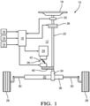
- a steering system 10 which is responsible for steering, i.e. laterally positioning, an autonomous vehicle 12.
- Propulsion of autonomous vehicle 12 may be provided by one or more know methods of propulsion, which may be, by way of non-limiting example only, an internal combustion engine, a fuel cell system, an electric motor supplied with electricity stored in a battery, and combinations of one or more thereof.
- Autonomous vehicle 12 includes a plurality of input devices 14 which sense and provide information about the surroundings of autonomous vehicle 12, sense the current operational state of autonomous vehicle 12, and provide information about the anticipated and desired operational state of autonomous vehicle 12, and may be, by way of non-limiting example only, cameras, radar, lidar, GPS, speed sensors, a compass, maps, wireless communication, sensors for monitoring the operational state of an internal combustion engine (not shown), battery-state sensors, operator-state sensors, or commanded operator inputs.
- Input devices 14 communicate respective data to an autonomous driving electronic control unit (ECU) 16 which processes the data in order to control the speed and direction of autonomous vehicle 12 by interacting with systems which control throttle and braking, i.e. longitudinal positioning, and also by interacting with steering system 10 to affect lateral positioning.
- ECU autonomous driving electronic control unit
- autonomous vehicle 12 refers to the individual that is responsible for controlling the manual aspects of autonomous vehicle 12 and is the equivalent of a driver in a conventional motor vehicle.
- Autonomous vehicle 12 may also be configured to operate in a manual mode where autonomous vehicle 12 navigates a route based on input from the operator of autonomous vehicle 12, i.e. the operator controls the longitudinal direction of autonomous vehicle 12 through conventional throttle and braking controls (not shown) and the operator also controls the lateral direction of autonomous vehicle 12 through a steering wheel 18 of steering system 10.
- Variable coupling member 26 together with clutch 38 allows various operating modes of steering system 10 to be carried out in response to a variety of driving scenarios. Variable coupling member 26 together with clutch 38 also allows the operator of autonomous vehicle 12 to regain control over steering actuator 24 under appropriate conditions while also minimizing risk to the operator of autonomous vehicle 12 when steering maneuvers carried out by steering actuator 24 would otherwise back-drive steering wheel 18 at a high rate of rotation over a large angular range.
Claims (15)
- Système de direction (10) pour un véhicule autonome (12), ledit système de direction (10) comprenant :un mécanisme de direction (20) ayant un élément d'entrée de mécanisme de direction (34) et un élément de sortie de mécanisme direction (36), ledit mécanisme de direction (20) étant configuré pour translater une rotation dudit élément d'entrée de mécanisme de direction (34) en un déplacement dudit élément de sortie de mécanisme de direction (36) qui est configuré pour affecter la position d'un pneumatique directionnel (28) dudit véhicule autonome (12), affectant ainsi la position latérale dudit véhicule autonome (12) ;une roue de direction (18) qui fournit une entrée mécanique audit élément d'entrée de mécanisme de direction (34) depuis un opérateur dudit véhicule autonome (12) ;un actionneur de direction (24) qui est mis en rotation pour appliquer un couple audit mécanisme de direction (20), induisant ainsi un déplacement dudit élément de sortie de mécanisme de direction (36) qui affecte la position dudit pneumatique directionnel (28) dudit véhicule autonome (12) ; etun élément de couplage variable (26) de manière fonctionnelle entre ledit actionneur de direction (24) et ledit mécanisme de direction (20) qui est configuré pour faire varier le couple qui peut être transmis depuis ledit actionneur de direction (24) audit mécanisme de direction (20),caractérisé parun moyen (38) de couplage et de découplage sélectif de ladite roue de direction (18) depuis ledit élément d'entrée de mécanisme de direction (34) via au moins :un couplage de ladite roue de direction (18) audit élément d'entrée de mécanisme de direction (34), et ce, dans un mode manuel de fonctionnement ou dans un premier mode autonome de fonctionnement dans lequel le couple qui peut être transmis depuis ledit actionneur de direction (24) audit mécanisme de direction (20) est bas ; etun découplage de ladite roue de direction (18) dudit élément d'entrée de mécanisme de direction (34), et ce, dans un second mode autonome de fonctionnement dans lequel le couple qui peut être transmis depuis ledit actionneur de direction (24) audit mécanisme de direction (20) est élevé, et un dispositif d'entrée (14) déterminant si un opérateur est en contact avec la roue de direction, dans lequel ledit moyen (38) est engagé en dépendance d'une sortie du dispositif d'entrée (14).
- Système de direction (10) selon la revendication 1, comprenant en outre :une unité de commande électronique de conduite autonome (16) ; etun dispositif d'entrée (14) qui fournit des données d'entrée de navigation à ladite unité de commande électronique de conduite autonome (16) ;dans lequel ladite unité de commande électronique de conduite autonome (16) est configurée pour traiter lesdites données d'entrée de navigation afin de générer des données de sortie de navigation qui sont transmises audit actionneur de direction (24) et audit élément de couplage variable (26), mettant ainsi en rotation ledit actionneur de direction (24) et faisant varier le couple qui peut être transmis depuis ledit actionneur de direction (24) audit mécanisme de direction (20).
- Système de direction (10) selon la revendication 1, dans lequel ledit mécanisme de direction (20) est un engrenage de direction (20) à crémaillère et pignon.
- Système de direction (10) selon la revendication 3, dans lequel ledit élément d'entrée de mécanisme de direction (34) est un engrenage à pignon (34) et ledit élément de sortie de mécanisme de direction (36) est une crémaillère (36).
- Système de direction (10) selon la revendication 1, dans lequel ledit élément de couplage variable (26) est un couplage à fluide magnétorhéologique.
- Système de direction (10) selon la revendication 1, comprenant en outre :une unité de commande électronique de conduite autonome (16) ; etun dispositif d'entrée (14) qui fournit des données d'entrée de navigation à ladite unité de commande électronique de conduite autonome (16) ;dans lequel ladite unité de commande électronique de conduite autonome (16) est configurée pour traiter lesdites données d'entrée de navigation afin de générer des données de sortie de navigation qui sont transmises audit actionneur de direction (24), audit élément de couplage variable (26) et audit moyen (38) de couplage et de découplage sélectif de ladite roue de direction (18) dudit élément d'entrée de mécanisme de direction (34), mettant ainsi en rotation ledit actionneur de direction (24), faisant varier le couple qui peut être transmis depuis ledit actionneur de direction (24) audit mécanisme de direction (20), et couplant et découplant ladite roue de direction (18) dudit élément d'entrée de mécanisme de direction (34), lorsque cela est déterminé comme étant nécessaire.
- Procédé de fonctionnement d'un système de direction (10) pour un véhicule autonome (12) dans lequel ledit système de direction (10) inclut un mécanisme de direction (20) ayant un élément d'entrée de mécanisme de direction (34) et un élément de sortie de mécanisme direction (36), ledit mécanisme de direction (20) étant configuré pour translater une rotation dudit élément d'entrée de mécanisme de direction (34) en un déplacement dudit élément de sortie de mécanisme de direction (36) qui est configuré pour affecter la position d'un pneumatique directionnel (28) dudit véhicule autonome (12), affectant ainsi la position latérale dudit véhicule autonome (12) ; une roue de direction (18) qui fournit une entrée mécanique audit élément d'entrée de mécanisme de direction (34) depuis un opérateur dudit véhicule autonome (12) ; un actionneur de direction (24) qui est mis en rotation pour appliquer un couple audit mécanisme de direction (20), induisant ainsi un déplacement dudit élément de sortie de mécanisme de direction (36) qui affecte la position dudit pneumatique directionnel (28) dudit véhicule autonome (12) ; un élément de couplage variable (26) de manière fonctionnelle entre ledit actionneur de direction (24) et ledit mécanisme de direction (20), un moyen (38) de couplage de découplage sélectif de ladite roue de direction (18) depuis ledit élément d'entrée de mécanisme de direction (34), et un dispositif d'entrée (14) déterminant si un opérateur est en contact avec la roue de direction,
caractérisé en ce que ledit procédé comprend les étapes additionnelles consistant à :ajouter ledit élément de couplage variable (26) pour faire varier le couple qui peut être transmis depuis ledit actionneur de direction (24) audit mécanisme de direction (20), et engager ledit moyen (38) en dépendance d'une entrée du dispositif d'entrée (14) ;coupler ladite roue de direction (18) audit élément d'entrée de mécanisme de direction (34) quand le couplage est effectué dans un mode manuel de fonctionnement ou dans un premier mode autonome de fonctionnement dans lequel le couple qui peut être transmis depuis ledit actionneur de direction (24) audit mécanisme de direction (20) est bas ; etdécoupler ladite roue de direction (18) dudit élément d'entrée de mécanisme de direction (34) quand le découplage est effectué dans un second mode autonome de fonctionnement dans lequel le couplage qui peut être transmis depuis ledit actionneur de direction (4) audit mécanisme de direction (20) est élevé. - Procédé selon la revendication 7, dans lequel le système de direction (10) inclut également une unité de commande électronique de conduite autonome (16) et un dispositif d'entrée (14) qui fournit des données d'entrée de navigation à ladite unité de commande électronique de conduite autonome (16), ledit procédé comprenant en outre les étapes consistant à :utiliser ladite unité de commande électronique de conduite autonome (16) pour traiter lesdites données d'entrée de navigation afin de générer des données de sortie de navigation qui sont transmises audit actionneur de direction (24) ;utiliser lesdites données de sortie de navigation pour mettre en rotation ledit actionneur de direction (24) ; etutiliser lesdites données de sortie de navigation pour faire varier le couple qui peut être transmis depuis ledit actionneur de direction (24) audit mécanisme de direction (20).
- Procédé selon la revendication 7, ledit procédé comprenant en outre l'étape consistant à coupler et à découpler ladite roue de direction (18) dudit élément d'entrée de mécanisme de direction (34).
- Procédé selon la revendication 7, ledit procédé comprenant en outre les étapes consistant à :fournir des données d'entrée de navigation à une unité de commande électronique de conduite autonome (16) dudit système de direction (10) ;utiliser ladite unité de commande électronique de conduite autonome (16) pour traiter lesdites données d'entrée de navigation afin de générer des données de sortie de navigation ;utiliser lesdites données de sortie de navigation pour mettre en rotation ledit actionneur de direction (24) ;utiliser lesdites données de sortie de navigation pour faire varier le couple qui peut être transmis depuis ledit actionneur de direction (24) audit mécanisme de direction (20) ; etutiliser lesdites données de sortie de navigation pour coupler et découpler ladite roue de direction (18) dudit élément d'entrée de mécanisme de direction (34).
- Procédé selon la revendication 7, comprenant en outre les étapes consistant à :découpler ladite roue de direction (18) dudit élément d'entrée de mécanisme de direction (34) ; etajuster ledit élément de couplage variable (26) pour augmenter le couple qui peut être transmis depuis ledit actionneur de direction (24) audit mécanisme de direction (20) sur la base d'un découplage réel ou escompté de ladite roue de direction (18) dudit élément d'entrée de mécanisme de direction (34).
- Procédé selon la revendication 7, comprenant en outre les étapes consistant à :coupler ladite roue de direction (18) audit élément d'entrée de mécanisme de direction (34) ; etajuster ledit élément de couplage variable (26) pour diminuer le couple qui peut être transmis depuis ledit actionneur de direction (24) audit mécanisme de direction (20) sur la base d'un couplage réel ou escompté de ladite roue de direction (18) audit élément d'entrée de mécanisme de direction (34).
- Procédé selon la revendication 7, comprenant en outre les étapes consistant à :commuter ledit système de direction (10) depuis ledit [[un]] mode manuel de fonctionnement où ledit opérateur dudit véhicule autonome (12) commande la direction latérale dudit véhicule automobile (12) via ladite roue de direction (18) vers l'[[un]] ou l'autre dudit premier ou dudit second mode autonome de fonctionnement où un module de commande électronique de conduite autonome est primairement responsable de la direction latérale dudit véhicule autonome (12) ; etfaire varier le couple qui peut être transmis depuis ledit actionneur de direction (24) audit mécanisme de direction (20) sur la base d'une commutation réelle ou escomptée depuis ledit mode manuel de fonctionnement audit soit premier soit second mode autonome de fonctionnement.
- Procédé selon la revendication 7, comprenant en outre les étapes consistant à :commuter ledit système de direction (10) depuis l'[[un]] ou l'autre dudit premier ou dudit second mode autonome de fonctionnement où un module de commande électronique de conduite autonome (16) est primairement responsable de la direction latérale dudit véhicule autonome (12) vers ledit [[un]] mode manuel de fonctionnement où ledit opérateur dudit véhicule autonome (12) commande la direction latérale dudit véhicule autonome (12) via ladite roue de direction (18) ; etfaire varier le couple qui peut être transmis depuis ledit actionneur de direction (24) audit mécanisme de direction (20) sur la base d'une commutation réelle ou escomptée depuis l'un ou l'autre dudit premier ou dudit second mode autonome de fonctionnement vers ledit mode manuel de fonctionnement.
- Procédé selon la revendication 14, dans lequel ladite étape consistant à faire varier le couple qui peut être transmis depuis ledit actionneur de direction (24) audit mécanisme de direction (20) inclut l'opération consistant à fixer le couple qui peut être transmis depuis ledit actionneur de direction (24) audit mécanisme de direction (20) à une amplitude qui peut être surmontée par ledit opérateur dudit véhicule autonome (12) via ladite roue de direction (18).
Applications Claiming Priority (2)
| Application Number | Priority Date | Filing Date | Title |
|---|---|---|---|
| US14/687,375 US9499202B2 (en) | 2015-04-15 | 2015-04-15 | Steering system and method for autonomous vehicles |
| PCT/US2016/026382 WO2016168052A1 (fr) | 2015-04-15 | 2016-04-07 | Système et procédé de direction pour véhicules autonomes |
Publications (3)
| Publication Number | Publication Date |
|---|---|
| EP3283349A1 EP3283349A1 (fr) | 2018-02-21 |
| EP3283349A4 EP3283349A4 (fr) | 2019-03-13 |
| EP3283349B1 true EP3283349B1 (fr) | 2022-01-19 |
Family
ID=57126812
Family Applications (1)
| Application Number | Title | Priority Date | Filing Date |
|---|---|---|---|
| EP16780478.0A Active EP3283349B1 (fr) | 2015-04-15 | 2016-04-07 | Système et procédé de direction pour véhicules autonomes |
Country Status (4)
| Country | Link |
|---|---|
| US (1) | US9499202B2 (fr) |
| EP (1) | EP3283349B1 (fr) |
| CN (1) | CN107531272B (fr) |
| WO (1) | WO2016168052A1 (fr) |
Families Citing this family (37)
| Publication number | Priority date | Publication date | Assignee | Title |
|---|---|---|---|---|
| DE102014226759A1 (de) * | 2014-12-22 | 2016-06-23 | Robert Bosch Gmbh | Verfahren und Vorrichtung zur Regelung und/oder Steuerung einer Querführung eines Fahrzeugsmittels eines Spurhalteassistenten und Spurhalteassistent |
| US10589774B2 (en) * | 2015-05-01 | 2020-03-17 | Steering Solutions Ip Holding Corporation | Counter rotation steering wheel |
| EP3702246A1 (fr) * | 2015-05-26 | 2020-09-02 | Exonetik Inc. | Système de direction actif utilisant des appareils d'embrayage à fluide magnétorhéologique |
| US20160375931A1 (en) | 2015-06-25 | 2016-12-29 | Steering Solutions Ip Holding Corporation | Rotation control system for a steering wheel and method |
| US9845103B2 (en) * | 2015-06-29 | 2017-12-19 | Steering Solutions Ip Holding Corporation | Steering arrangement |
| KR101792994B1 (ko) * | 2015-08-28 | 2017-11-02 | 엘지전자 주식회사 | 자율 주행 차량 |
| US9845106B2 (en) | 2015-08-31 | 2017-12-19 | Steering Solutions Ip Holding Corporation | Overload protection for belt drive mechanism |
| US10160472B2 (en) * | 2015-10-20 | 2018-12-25 | Steering Solutions Ip Holding Corporation | Steering column with stationary hub |
| US9834121B2 (en) | 2015-10-22 | 2017-12-05 | Steering Solutions Ip Holding Corporation | Tray table, steering wheel having tray table, and vehicle having steering wheel |
| US10322682B2 (en) | 2016-03-03 | 2019-06-18 | Steering Solutions Ip Holding Corporation | Steering wheel with keyboard |
| US9821726B2 (en) | 2016-03-03 | 2017-11-21 | Steering Solutions Ip Holding Corporation | Steering wheel with keyboard |
| DE102016008365A1 (de) * | 2016-07-08 | 2018-01-11 | Audi Ag | Proaktive Steuerung eines Assistenzsystems eines Kraftfahrzeugs |
| US10160473B2 (en) | 2016-09-13 | 2018-12-25 | Steering Solutions Ip Holding Corporation | Steering column decoupling system |
| US10144383B2 (en) | 2016-09-29 | 2018-12-04 | Steering Solutions Ip Holding Corporation | Steering wheel with video screen and airbag |
| EP3360757B1 (fr) | 2017-02-10 | 2019-10-02 | Volvo Car Corporation | Gestionnaire de couple de braquage avancé destiné à un système d'aide au conducteur d'un véhicule routier |
| EP3375696B1 (fr) | 2017-03-17 | 2019-11-20 | Volvo Car Corporation | Gestionnaire de couple de braquage destinés à un système d'aide au conducteur d'un véhicule routier |
| EP3378731B1 (fr) * | 2017-03-20 | 2020-01-15 | Volvo Car Corporation | Appareil et procédé de commande d'angle de roue fonction de l'activité du conducteur (adas) |
| EP3378733B1 (fr) | 2017-03-20 | 2020-01-15 | Volvo Car Corporation | Appareil et procédé de commande d'angle de roue en fonction de la situation (had ou adas) |
| US10633025B2 (en) | 2017-09-26 | 2020-04-28 | Toyota Research Institute, Inc. | Systems and methods for switching between a driver mode and an autonomous driving mode for a vehicle |
| US10996673B1 (en) | 2017-09-28 | 2021-05-04 | Apple Inc. | Manual override |
| DE112019000257T5 (de) * | 2018-01-04 | 2020-10-08 | Joyson Safety Systems Acquisition Llc | Systeme und Verfahren zur autonomen Vorderradlenkung |
| US10759474B2 (en) * | 2018-04-09 | 2020-09-01 | Ford Global Technologies, Llc | Stowable steering wheel |
| CN108394461B (zh) * | 2018-05-02 | 2019-11-26 | 吉林大学 | 单筒锥齿轮式磁流变液力感反馈装置及其使用方法 |
| CN108372883B (zh) * | 2018-05-02 | 2019-11-26 | 吉林大学 | 磁流变液旋转扭簧力感反馈装置及其使用方法 |
| CN108583676B (zh) * | 2018-05-02 | 2019-11-26 | 吉林大学 | 磁流变液双转子力感反馈装置及其使用方法 |
| CN110509992B (zh) * | 2018-05-21 | 2024-02-20 | 纳博特斯克有限公司 | 转向装置 |
| JP7155668B2 (ja) * | 2018-06-29 | 2022-10-19 | いすゞ自動車株式会社 | 操舵制御装置および操舵制御方法 |
| EP3650298B1 (fr) | 2018-11-12 | 2024-03-27 | Infosys Limited | Système de direction et de freinage automatique intégré comme kit de modernisation pour véhicules autonomes |
| CN109481918B (zh) * | 2018-12-18 | 2024-03-19 | 常州泰德高尔夫用品有限公司 | 一种多功能高尔夫球车 |
| WO2020140603A1 (fr) * | 2019-01-02 | 2020-07-09 | 南京航空航天大学 | Système de direction électro-hydraulique à crémaillère et pignon à base de fluide magnéto-rhéologique et procédé d'optimisation |
| US11092970B2 (en) * | 2019-02-07 | 2021-08-17 | Ford Global Technologies, Llc | Autonomous vehicle systems utilizing vehicle-to-vehicle communication |
| JP7205377B2 (ja) * | 2019-05-20 | 2023-01-17 | トヨタ自動車株式会社 | 自動運転車両 |
| US11077863B2 (en) * | 2019-08-14 | 2021-08-03 | Waymo Llc | Secondary disengage alert for autonomous vehicles |
| CN112158255A (zh) * | 2020-08-20 | 2021-01-01 | 南京中智腾飞航空科技研究院有限公司 | 一种北斗导航自动驾驶方向盘装置 |
| CN112606820B (zh) * | 2020-12-17 | 2022-01-04 | 成都天予创美科技有限公司 | 汽车安全系统 |
| CN112744288B (zh) * | 2021-01-26 | 2022-08-26 | 上海工程技术大学 | 一种基于多盘式磁流变液离合器的电动助力转向系统 |
| WO2024038424A1 (fr) | 2022-08-19 | 2024-02-22 | Institut Teknologi Bandung | Commande manuelle d'outils de commande de signal électrique sur des camions porte-conteneurs à moteurs hydrauliques |
Family Cites Families (22)
| Publication number | Priority date | Publication date | Assignee | Title |
|---|---|---|---|---|
| FR2683645B1 (fr) * | 1991-11-12 | 1997-03-14 | Merobel | Dispositif electromagnetique d'assistance de direction pour vehicule. |
| US5598908A (en) | 1995-06-05 | 1997-02-04 | Gse, Inc. | Magnetorheological fluid coupling device and torque load simulator system |
| DE19837810A1 (de) * | 1998-08-20 | 2000-02-24 | Mannesmann Sachs Ag | Elektromotorisches Lenkungssystem, insbesondere Servolenkungssystem für ein Kraftfahrzeug |
| JP3498910B2 (ja) | 2000-09-05 | 2004-02-23 | 日産自動車株式会社 | 車線追従制御装置 |
| US6450286B1 (en) | 2000-10-24 | 2002-09-17 | Ford Global Tech., Inc. | Rack and pinion power steering system with variable damping characteristics |
| US6454044B1 (en) | 2001-04-17 | 2002-09-24 | Delphi Technologies, Inc. | Gearing without backlash for electric power steering |
| WO2002102640A2 (fr) * | 2001-06-19 | 2002-12-27 | Delphi Technologies, Inc. | Actionneur de roue de direction guide par cables |
| US7240485B2 (en) | 2003-04-07 | 2007-07-10 | Gm Global Technology Operations, Inc. | Power steering system |
| US7510038B2 (en) | 2003-06-11 | 2009-03-31 | Delphi Technologies, Inc. | Steering system with lane keeping integration |
| JP4389567B2 (ja) * | 2003-12-03 | 2009-12-24 | 日産自動車株式会社 | 車線逸脱防止装置 |
| JP4483327B2 (ja) | 2004-02-13 | 2010-06-16 | 株式会社ジェイテクト | 油圧式のギア比可変パワーステアリング装置 |
| US7306535B2 (en) * | 2004-06-29 | 2007-12-11 | Delphi Technologies, Inc. | Vehicle steering device and method |
| US7530422B2 (en) * | 2004-09-17 | 2009-05-12 | Delphi Technologies, Inc. | Force and position control for active front steering |
| DE102005034636B3 (de) | 2005-07-20 | 2007-03-22 | Takata-Petri Ag | Lenkeinrichtung für eine Überlagerungslenkung |
| WO2007048029A2 (fr) * | 2005-10-21 | 2007-04-26 | Deere & Company | Systemes et procedes d'evitement d'obstacles |
| US8150582B2 (en) | 2009-04-20 | 2012-04-03 | Ford Global Technologies, Llc | Systems and methods for decoupling steering rack force disturbances in electric steering |
| KR101708083B1 (ko) | 2009-08-19 | 2017-02-27 | 켈시-헤이즈 컴파니 | 자율적으로 구동하는 차량의 안전한 스티어링 시스템 |
| US8994521B2 (en) | 2011-06-29 | 2015-03-31 | GM Global Technology Operations LLC | Steering wheels for vehicle control in manual and autonomous driving |
| US9073576B2 (en) * | 2011-09-02 | 2015-07-07 | GM Global Technology Operations LLC | System and method for smooth steering override transition during automated lane centering |
| KR101326811B1 (ko) * | 2011-11-21 | 2013-11-11 | 현대자동차주식회사 | 차량 조향 시스템 및 이에 대한 전류 공급 방법 |
| US9333983B2 (en) | 2013-03-15 | 2016-05-10 | Volkswagen Ag | Dual-state steering wheel/input device |
| US10286953B2 (en) * | 2014-09-17 | 2019-05-14 | Ford Global Technologies, Llc | Autopark steering wheel snap reduction |
-
2015
- 2015-04-15 US US14/687,375 patent/US9499202B2/en active Active
-
2016
- 2016-04-07 EP EP16780478.0A patent/EP3283349B1/fr active Active
- 2016-04-07 WO PCT/US2016/026382 patent/WO2016168052A1/fr active Application Filing
- 2016-04-07 CN CN201680021921.3A patent/CN107531272B/zh active Active
Also Published As
| Publication number | Publication date |
|---|---|
| EP3283349A1 (fr) | 2018-02-21 |
| EP3283349A4 (fr) | 2019-03-13 |
| US9499202B2 (en) | 2016-11-22 |
| CN107531272B (zh) | 2019-11-05 |
| CN107531272A (zh) | 2018-01-02 |
| US20160304123A1 (en) | 2016-10-20 |
| WO2016168052A1 (fr) | 2016-10-20 |
Similar Documents
| Publication | Publication Date | Title |
|---|---|---|
| EP3283349B1 (fr) | Système et procédé de direction pour véhicules autonomes | |
| CN108163042B (zh) | 具有基于用户体验的自动驾驶至手动驾驶转换系统和方法的车辆转向系统 | |
| US11072366B2 (en) | Method for controlling a steer-by-wire steering system with a reduced feedback in automatic drive mode | |
| CN109291991B (zh) | 一种双电机线控复合转向系统及其控制方法 | |
| EP1481874B1 (fr) | Système de direction et méthode de commande associe pour un véhicule | |
| JP6016680B2 (ja) | 走行車両 | |
| JP6187090B2 (ja) | 車両用運転制御装置及び車両用運転制御方法 | |
| JP5918162B2 (ja) | 走行車両 | |
| EP1486397B1 (fr) | Système de sécurité pour système de direction d'un véhicule automobile | |
| CN108238099B (zh) | 车辆行驶控制装置及自主驾驶控制方法 | |
| CN106794834B (zh) | 用于运行机动车的方法和装置 | |
| US11577776B2 (en) | Managing redundant steering system for autonomous vehicles | |
| US9925988B1 (en) | Steering and braking control system | |
| JP2021502923A (ja) | 車両の少なくとも1つの車両コンポーネントを検査する方法 | |
| CN112543727A (zh) | 转向机构、转向系统、车辆及控制方法 | |
| US11459024B2 (en) | Multifunctional steering column, transportation vehicle, and method for operating a transportation vehicle | |
| WO2019136245A1 (fr) | Systèmes et procédés de direction autonome de roues avant | |
| EP3059141B1 (fr) | Système de direction active pour autobus articulé | |
| CN115246438A (zh) | 用于操纵车辆的方法 | |
| CN114684242A (zh) | 移动体 | |
| EP3810485B1 (fr) | Ensemble de direction pour un véhicule | |
| KR102515225B1 (ko) | 조향 제어 장치 및 방법과, 조향 장치 | |
| KR102628128B1 (ko) | 차량용 전동식 파워 스티어링 장치 및 그것의 제어방법 | |
| US20240101187A1 (en) | Steer-by-wire system capable of controlling steering in case of breakdown of steering feedback actuator and method of controlling steering in case of breakdown of steering feedback actuator | |
| CN114684259A (zh) | 移动体 |
Legal Events
| Date | Code | Title | Description |
|---|---|---|---|
| STAA | Information on the status of an ep patent application or granted ep patent |
Free format text: STATUS: THE INTERNATIONAL PUBLICATION HAS BEEN MADE |
|
| PUAI | Public reference made under article 153(3) epc to a published international application that has entered the european phase |
Free format text: ORIGINAL CODE: 0009012 |
|
| STAA | Information on the status of an ep patent application or granted ep patent |
Free format text: STATUS: REQUEST FOR EXAMINATION WAS MADE |
|
| 17P | Request for examination filed |
Effective date: 20171115 |
|
| AK | Designated contracting states |
Kind code of ref document: A1 Designated state(s): AL AT BE BG CH CY CZ DE DK EE ES FI FR GB GR HR HU IE IS IT LI LT LU LV MC MK MT NL NO PL PT RO RS SE SI SK SM TR |
|
| AX | Request for extension of the european patent |
Extension state: BA ME |
|
| DAV | Request for validation of the european patent (deleted) | ||
| DAX | Request for extension of the european patent (deleted) | ||
| RAP1 | Party data changed (applicant data changed or rights of an application transferred) |
Owner name: APTIV TECHNOLOGIES LIMITED |
|
| A4 | Supplementary search report drawn up and despatched |
Effective date: 20190213 |
|
| RIC1 | Information provided on ipc code assigned before grant |
Ipc: B62D 6/00 20060101AFI20190207BHEP Ipc: B62D 5/22 20060101ALI20190207BHEP Ipc: B60W 10/20 20060101ALI20190207BHEP |
|
| STAA | Information on the status of an ep patent application or granted ep patent |
Free format text: STATUS: EXAMINATION IS IN PROGRESS |
|
| 17Q | First examination report despatched |
Effective date: 20200623 |
|
| STAA | Information on the status of an ep patent application or granted ep patent |
Free format text: STATUS: EXAMINATION IS IN PROGRESS |
|
| REG | Reference to a national code |
Ref country code: DE Ref legal event code: R079 Ref document number: 602016068492 Country of ref document: DE Free format text: PREVIOUS MAIN CLASS: B62D0006000000 Ipc: B62D0005040000 |
|
| RIC1 | Information provided on ipc code assigned before grant |
Ipc: B62D 5/04 20060101AFI20210607BHEP Ipc: B62D 15/02 20060101ALI20210607BHEP Ipc: B62D 6/00 20060101ALI20210607BHEP Ipc: B62D 5/22 20060101ALI20210607BHEP Ipc: B60W 10/20 20060101ALI20210607BHEP |
|
| GRAP | Despatch of communication of intention to grant a patent |
Free format text: ORIGINAL CODE: EPIDOSNIGR1 |
|
| STAA | Information on the status of an ep patent application or granted ep patent |
Free format text: STATUS: GRANT OF PATENT IS INTENDED |
|
| INTG | Intention to grant announced |
Effective date: 20210806 |
|
| GRAS | Grant fee paid |
Free format text: ORIGINAL CODE: EPIDOSNIGR3 |
|
| GRAA | (expected) grant |
Free format text: ORIGINAL CODE: 0009210 |
|
| STAA | Information on the status of an ep patent application or granted ep patent |
Free format text: STATUS: THE PATENT HAS BEEN GRANTED |
|
| AK | Designated contracting states |
Kind code of ref document: B1 Designated state(s): AL AT BE BG CH CY CZ DE DK EE ES FI FR GB GR HR HU IE IS IT LI LT LU LV MC MK MT NL NO PL PT RO RS SE SI SK SM TR |
|
| REG | Reference to a national code |
Ref country code: GB Ref legal event code: FG4D |
|
| REG | Reference to a national code |
Ref country code: CH Ref legal event code: EP |
|
| REG | Reference to a national code |
Ref country code: DE Ref legal event code: R096 Ref document number: 602016068492 Country of ref document: DE |
|
| REG | Reference to a national code |
Ref country code: AT Ref legal event code: REF Ref document number: 1463641 Country of ref document: AT Kind code of ref document: T Effective date: 20220215 |
|
| REG | Reference to a national code |
Ref country code: IE Ref legal event code: FG4D |
|
| REG | Reference to a national code |
Ref country code: LT Ref legal event code: MG9D |
|
| REG | Reference to a national code |
Ref country code: NL Ref legal event code: MP Effective date: 20220119 |
|
| REG | Reference to a national code |
Ref country code: AT Ref legal event code: MK05 Ref document number: 1463641 Country of ref document: AT Kind code of ref document: T Effective date: 20220119 |
|
| PG25 | Lapsed in a contracting state [announced via postgrant information from national office to epo] |
Ref country code: NL Free format text: LAPSE BECAUSE OF FAILURE TO SUBMIT A TRANSLATION OF THE DESCRIPTION OR TO PAY THE FEE WITHIN THE PRESCRIBED TIME-LIMIT Effective date: 20220119 |
|
| PG25 | Lapsed in a contracting state [announced via postgrant information from national office to epo] |
Ref country code: SE Free format text: LAPSE BECAUSE OF FAILURE TO SUBMIT A TRANSLATION OF THE DESCRIPTION OR TO PAY THE FEE WITHIN THE PRESCRIBED TIME-LIMIT Effective date: 20220119 Ref country code: RS Free format text: LAPSE BECAUSE OF FAILURE TO SUBMIT A TRANSLATION OF THE DESCRIPTION OR TO PAY THE FEE WITHIN THE PRESCRIBED TIME-LIMIT Effective date: 20220119 Ref country code: PT Free format text: LAPSE BECAUSE OF FAILURE TO SUBMIT A TRANSLATION OF THE DESCRIPTION OR TO PAY THE FEE WITHIN THE PRESCRIBED TIME-LIMIT Effective date: 20220519 Ref country code: NO Free format text: LAPSE BECAUSE OF FAILURE TO SUBMIT A TRANSLATION OF THE DESCRIPTION OR TO PAY THE FEE WITHIN THE PRESCRIBED TIME-LIMIT Effective date: 20220419 Ref country code: LT Free format text: LAPSE BECAUSE OF FAILURE TO SUBMIT A TRANSLATION OF THE DESCRIPTION OR TO PAY THE FEE WITHIN THE PRESCRIBED TIME-LIMIT Effective date: 20220119 Ref country code: HR Free format text: LAPSE BECAUSE OF FAILURE TO SUBMIT A TRANSLATION OF THE DESCRIPTION OR TO PAY THE FEE WITHIN THE PRESCRIBED TIME-LIMIT Effective date: 20220119 Ref country code: ES Free format text: LAPSE BECAUSE OF FAILURE TO SUBMIT A TRANSLATION OF THE DESCRIPTION OR TO PAY THE FEE WITHIN THE PRESCRIBED TIME-LIMIT Effective date: 20220119 Ref country code: BG Free format text: LAPSE BECAUSE OF FAILURE TO SUBMIT A TRANSLATION OF THE DESCRIPTION OR TO PAY THE FEE WITHIN THE PRESCRIBED TIME-LIMIT Effective date: 20220419 |
|
| PG25 | Lapsed in a contracting state [announced via postgrant information from national office to epo] |
Ref country code: PL Free format text: LAPSE BECAUSE OF FAILURE TO SUBMIT A TRANSLATION OF THE DESCRIPTION OR TO PAY THE FEE WITHIN THE PRESCRIBED TIME-LIMIT Effective date: 20220119 Ref country code: LV Free format text: LAPSE BECAUSE OF FAILURE TO SUBMIT A TRANSLATION OF THE DESCRIPTION OR TO PAY THE FEE WITHIN THE PRESCRIBED TIME-LIMIT Effective date: 20220119 Ref country code: GR Free format text: LAPSE BECAUSE OF FAILURE TO SUBMIT A TRANSLATION OF THE DESCRIPTION OR TO PAY THE FEE WITHIN THE PRESCRIBED TIME-LIMIT Effective date: 20220420 Ref country code: FI Free format text: LAPSE BECAUSE OF FAILURE TO SUBMIT A TRANSLATION OF THE DESCRIPTION OR TO PAY THE FEE WITHIN THE PRESCRIBED TIME-LIMIT Effective date: 20220119 Ref country code: AT Free format text: LAPSE BECAUSE OF FAILURE TO SUBMIT A TRANSLATION OF THE DESCRIPTION OR TO PAY THE FEE WITHIN THE PRESCRIBED TIME-LIMIT Effective date: 20220119 |
|
| PG25 | Lapsed in a contracting state [announced via postgrant information from national office to epo] |
Ref country code: IS Free format text: LAPSE BECAUSE OF FAILURE TO SUBMIT A TRANSLATION OF THE DESCRIPTION OR TO PAY THE FEE WITHIN THE PRESCRIBED TIME-LIMIT Effective date: 20220519 |
|
| REG | Reference to a national code |
Ref country code: DE Ref legal event code: R097 Ref document number: 602016068492 Country of ref document: DE |
|
| PG25 | Lapsed in a contracting state [announced via postgrant information from national office to epo] |
Ref country code: SM Free format text: LAPSE BECAUSE OF FAILURE TO SUBMIT A TRANSLATION OF THE DESCRIPTION OR TO PAY THE FEE WITHIN THE PRESCRIBED TIME-LIMIT Effective date: 20220119 Ref country code: SK Free format text: LAPSE BECAUSE OF FAILURE TO SUBMIT A TRANSLATION OF THE DESCRIPTION OR TO PAY THE FEE WITHIN THE PRESCRIBED TIME-LIMIT Effective date: 20220119 Ref country code: RO Free format text: LAPSE BECAUSE OF FAILURE TO SUBMIT A TRANSLATION OF THE DESCRIPTION OR TO PAY THE FEE WITHIN THE PRESCRIBED TIME-LIMIT Effective date: 20220119 Ref country code: EE Free format text: LAPSE BECAUSE OF FAILURE TO SUBMIT A TRANSLATION OF THE DESCRIPTION OR TO PAY THE FEE WITHIN THE PRESCRIBED TIME-LIMIT Effective date: 20220119 Ref country code: DK Free format text: LAPSE BECAUSE OF FAILURE TO SUBMIT A TRANSLATION OF THE DESCRIPTION OR TO PAY THE FEE WITHIN THE PRESCRIBED TIME-LIMIT Effective date: 20220119 Ref country code: CZ Free format text: LAPSE BECAUSE OF FAILURE TO SUBMIT A TRANSLATION OF THE DESCRIPTION OR TO PAY THE FEE WITHIN THE PRESCRIBED TIME-LIMIT Effective date: 20220119 |
|
| PLBE | No opposition filed within time limit |
Free format text: ORIGINAL CODE: 0009261 |
|
| STAA | Information on the status of an ep patent application or granted ep patent |
Free format text: STATUS: NO OPPOSITION FILED WITHIN TIME LIMIT |
|
| PG25 | Lapsed in a contracting state [announced via postgrant information from national office to epo] |
Ref country code: AL Free format text: LAPSE BECAUSE OF FAILURE TO SUBMIT A TRANSLATION OF THE DESCRIPTION OR TO PAY THE FEE WITHIN THE PRESCRIBED TIME-LIMIT Effective date: 20220119 |
|
| REG | Reference to a national code |
Ref country code: CH Ref legal event code: PL |
|
| 26N | No opposition filed |
Effective date: 20221020 |
|
| REG | Reference to a national code |
Ref country code: BE Ref legal event code: MM Effective date: 20220430 |
|
| PG25 | Lapsed in a contracting state [announced via postgrant information from national office to epo] |
Ref country code: MC Free format text: LAPSE BECAUSE OF FAILURE TO SUBMIT A TRANSLATION OF THE DESCRIPTION OR TO PAY THE FEE WITHIN THE PRESCRIBED TIME-LIMIT Effective date: 20220119 Ref country code: LU Free format text: LAPSE BECAUSE OF NON-PAYMENT OF DUE FEES Effective date: 20220407 Ref country code: LI Free format text: LAPSE BECAUSE OF NON-PAYMENT OF DUE FEES Effective date: 20220430 Ref country code: CH Free format text: LAPSE BECAUSE OF NON-PAYMENT OF DUE FEES Effective date: 20220430 |
|
| PG25 | Lapsed in a contracting state [announced via postgrant information from national office to epo] |
Ref country code: SI Free format text: LAPSE BECAUSE OF FAILURE TO SUBMIT A TRANSLATION OF THE DESCRIPTION OR TO PAY THE FEE WITHIN THE PRESCRIBED TIME-LIMIT Effective date: 20220119 Ref country code: BE Free format text: LAPSE BECAUSE OF NON-PAYMENT OF DUE FEES Effective date: 20220430 |
|
| PG25 | Lapsed in a contracting state [announced via postgrant information from national office to epo] |
Ref country code: IE Free format text: LAPSE BECAUSE OF NON-PAYMENT OF DUE FEES Effective date: 20220407 |
|
| P01 | Opt-out of the competence of the unified patent court (upc) registered |
Effective date: 20230424 |
|
| PG25 | Lapsed in a contracting state [announced via postgrant information from national office to epo] |
Ref country code: IT Free format text: LAPSE BECAUSE OF FAILURE TO SUBMIT A TRANSLATION OF THE DESCRIPTION OR TO PAY THE FEE WITHIN THE PRESCRIBED TIME-LIMIT Effective date: 20220119 |
|
| PGFP | Annual fee paid to national office [announced via postgrant information from national office to epo] |
Ref country code: FR Payment date: 20230428 Year of fee payment: 8 Ref country code: DE Payment date: 20230426 Year of fee payment: 8 |
|
| PGFP | Annual fee paid to national office [announced via postgrant information from national office to epo] |
Ref country code: GB Payment date: 20230419 Year of fee payment: 8 |
|
| PG25 | Lapsed in a contracting state [announced via postgrant information from national office to epo] |
Ref country code: HU Free format text: LAPSE BECAUSE OF FAILURE TO SUBMIT A TRANSLATION OF THE DESCRIPTION OR TO PAY THE FEE WITHIN THE PRESCRIBED TIME-LIMIT; INVALID AB INITIO Effective date: 20160407 |