EP3282893B1 - Rechteckiger rahmen mit höhenverstellung für eine erste und/oder zweite vorrichtung zur ankopplung an den rahmen - Google Patents
Rechteckiger rahmen mit höhenverstellung für eine erste und/oder zweite vorrichtung zur ankopplung an den rahmen Download PDFInfo
- Publication number
- EP3282893B1 EP3282893B1 EP16734475.3A EP16734475A EP3282893B1 EP 3282893 B1 EP3282893 B1 EP 3282893B1 EP 16734475 A EP16734475 A EP 16734475A EP 3282893 B1 EP3282893 B1 EP 3282893B1
- Authority
- EP
- European Patent Office
- Prior art keywords
- frame
- adjusting means
- coupling
- constant
- adjustable
- Prior art date
- Legal status (The legal status is an assumption and is not a legal conclusion. Google has not performed a legal analysis and makes no representation as to the accuracy of the status listed.)
- Active
Links
Images


Classifications
-
- A—HUMAN NECESSITIES
- A47—FURNITURE; DOMESTIC ARTICLES OR APPLIANCES; COFFEE MILLS; SPICE MILLS; SUCTION CLEANERS IN GENERAL
- A47B—TABLES; DESKS; OFFICE FURNITURE; CABINETS; DRAWERS; GENERAL DETAILS OF FURNITURE
- A47B9/00—Tables with tops of variable height
- A47B9/02—Tables with tops of variable height with balancing device, e.g. by springs, by weight
-
- A—HUMAN NECESSITIES
- A47—FURNITURE; DOMESTIC ARTICLES OR APPLIANCES; COFFEE MILLS; SPICE MILLS; SUCTION CLEANERS IN GENERAL
- A47B—TABLES; DESKS; OFFICE FURNITURE; CABINETS; DRAWERS; GENERAL DETAILS OF FURNITURE
- A47B97/00—Furniture or accessories for furniture, not provided for in other groups of this subclass
- A47B97/04—Easels or stands for blackboards or the like
- A47B97/06—Easels or stands for blackboards or the like with means for balancing weight of blackboards or the like, e.g. connected to wall
-
- F—MECHANICAL ENGINEERING; LIGHTING; HEATING; WEAPONS; BLASTING
- F16—ENGINEERING ELEMENTS AND UNITS; GENERAL MEASURES FOR PRODUCING AND MAINTAINING EFFECTIVE FUNCTIONING OF MACHINES OR INSTALLATIONS; THERMAL INSULATION IN GENERAL
- F16M—FRAMES, CASINGS OR BEDS OF ENGINES, MACHINES OR APPARATUS, NOT SPECIFIC TO ENGINES, MACHINES OR APPARATUS PROVIDED FOR ELSEWHERE; STANDS; SUPPORTS
- F16M11/00—Stands or trestles as supports for apparatus or articles placed thereon ; Stands for scientific apparatus such as gravitational force meters
- F16M11/02—Heads
- F16M11/04—Means for attachment of apparatus; Means allowing adjustment of the apparatus relatively to the stand
- F16M11/043—Allowing translations
- F16M11/046—Allowing translations adapted to upward-downward translation movement
-
- F—MECHANICAL ENGINEERING; LIGHTING; HEATING; WEAPONS; BLASTING
- F16—ENGINEERING ELEMENTS AND UNITS; GENERAL MEASURES FOR PRODUCING AND MAINTAINING EFFECTIVE FUNCTIONING OF MACHINES OR INSTALLATIONS; THERMAL INSULATION IN GENERAL
- F16M—FRAMES, CASINGS OR BEDS OF ENGINES, MACHINES OR APPARATUS, NOT SPECIFIC TO ENGINES, MACHINES OR APPARATUS PROVIDED FOR ELSEWHERE; STANDS; SUPPORTS
- F16M11/00—Stands or trestles as supports for apparatus or articles placed thereon ; Stands for scientific apparatus such as gravitational force meters
- F16M11/02—Heads
- F16M11/18—Heads with mechanism for moving the apparatus relatively to the stand
-
- A—HUMAN NECESSITIES
- A47—FURNITURE; DOMESTIC ARTICLES OR APPLIANCES; COFFEE MILLS; SPICE MILLS; SUCTION CLEANERS IN GENERAL
- A47B—TABLES; DESKS; OFFICE FURNITURE; CABINETS; DRAWERS; GENERAL DETAILS OF FURNITURE
- A47B9/00—Tables with tops of variable height
- A47B9/12—Tables with tops of variable height with flexible height-adjusting means, e.g. rope, chain
-
- F—MECHANICAL ENGINEERING; LIGHTING; HEATING; WEAPONS; BLASTING
- F16—ENGINEERING ELEMENTS AND UNITS; GENERAL MEASURES FOR PRODUCING AND MAINTAINING EFFECTIVE FUNCTIONING OF MACHINES OR INSTALLATIONS; THERMAL INSULATION IN GENERAL
- F16M—FRAMES, CASINGS OR BEDS OF ENGINES, MACHINES OR APPARATUS, NOT SPECIFIC TO ENGINES, MACHINES OR APPARATUS PROVIDED FOR ELSEWHERE; STANDS; SUPPORTS
- F16M2200/00—Details of stands or supports
- F16M2200/04—Balancing means
- F16M2200/048—Balancing means for balancing translational movement of the undercarriage
Definitions
- the invention relates to a rectangular frame, which frame is formed by at least a first upright, upper beam, second upright and lower beam, wherein the frame is provided with first coupling means and the frame is configured for coupling of a first device, such as a desk top, black/whiteboard or painting, to a first side of the frame by means of the first coupling means.
- a first device such as a desk top, black/whiteboard or painting
- a rectangular frame according to the invention is known in the field.
- GB1005570A and WO03/103447A1 show similar frames which are considered useful for understanding the invention.
- the known frame has the drawback that the device, after being coupled to the frame, is connected rigidly to the frame.
- the frame according to the invention has for this purpose the feature that the frame is also configured for adjustable placing of the first device in the height relative to the frame, wherein the frame is provided with first adjusting means for adjusting the first coupling means and a first operating member for operating the first adjusting means, wherein the first coupling means comprise a first and second coupling element, which first and second coupling elements are arranged for simultaneous adjustable displacement to substantially the same height in respectively the first and second upright and are connected respectively by means of a first and second cord to the first adjusting means, wherein the first adjusting means comprise at least one constant-force spring, wherein a first outer end of each constant-force spring is connected to both the first and the second cord.
- the frame according to the invention can be applied as sub-frame for a desk, wherein the frame allows a height adjustment of a desk top.
- Another application for the frame according to the invention is making a flat device, such as for instance a painting, black/whiteboard, television etc. for hanging, height-adjustable on a vertical surface such as a wall.
- the frame according to the invention can be utilized for multiple applications and is not limited to one application, such as making desks height-adjustable, the production of the frame in large numbers is economically feasible.
- the frame according to the invention does not depend on electricity, thereby further increasing the utility of the frame.
- the correct force springs can be chosen subject to the weight of the device in order to enable movement of the device in the height using the spring force of the constant-force springs and gravitational force.
- the constant-force springs produce a constant force over a long spring travel, whereby a user of the frame according to the invention can exert a uniform force on the device during displacement of the device in the height.
- the frame is also configured for adjusting in the height relative to the frame a second device, such as a desk top, black/whiteboard or painting, for coupling to a second side of the frame.
- the frame is provided for this purpose with second coupling means for coupling of the second device, second adjusting means for adjusting the second coupling means and a second operating member for operating the second adjusting means, wherein the second coupling means comprise a third and fourth coupling element, which third and fourth coupling elements are arranged for simultaneous adjustable displacement to substantially the same height in respectively the first and second upright, and are connected respectively by means of a third and fourth cord to the second adjusting means, wherein the second adjusting means comprise at least one constant-force spring, wherein a first outer end of each constant-force spring of the second adjusting means is connected to both the third and the fourth cord.
- the first and/or second adjusting means preferably comprise a housing which substantially comprises each constant-force spring in unloaded state, wherein a second outer end of each constant-force spring is connected fixedly to the housing.
- each constant-force spring or a set of constant-force springs is preferably provided with a brake which engages on the constant-force spring, and which brake can be operated via the first and/or second operating member. Using the brake the device can be locked in a simple manner at a height to be determined by a user.
- each constant-force spring is preferably mutually connected here by means of a brake cable and the first and/or second operating member engages on the brake cable.
- the first and/or second adjusting means comprise a number of, preferably two, pairs of constant-force springs, wherein each force spring comprises a rolled-up leaf spring, and each pair of leaf springs is placed in mirrored arrangement in the housing such that the outer sides of the unrolled parts of each pair of leaf springs are adjacent.
- the start of each leaf spring for instance the first 5 cm, is preferably flat here.
- This arrangement of the leaf springs in the housing ensures that the leaf springs unwind in a straight line.
- the first adjusting means are preferably placed close to a bottom corner of the frame formed by the first upright or the second upright and the lower beam, and the first and second cords are connected to the first adjusting means at an angle of about 30 to 60 degrees relative to the lower beam. Because of these measures the one or more constant-force springs of the first adjusting means have an extension which is greater than the height of the frame.
- the first adjusting means can also be mounted on a first upright.
- the first and second cords are then preferably guided horizontally to the first adjusting means via a roller on the second upright.
- the second adjusting means are preferably placed close to a bottom corner of the frame and the third and fourth cords are connected to the second adjusting means at an angle of about 30 to 60 degrees relative to the lower beam.
- the first and second adjusting means are preferably placed here close to different bottom corners.
- the first adjusting means are arranged for displacement along a first path in the frame and the first and second cords are connected to the first adjusting means (7) at an angle adjustable relative to the first path.
- the frame is preferably provided here with a first guide channel which is mounted rotatably at a first outer end on the frame and which extends from the first outer end substantially in the direction of the first path.
- the angle between the longitudinal direction of the first guide channel and the first path is for this purpose adjustable.
- the first adjusting means are also connected to the first and second cords by means of a first guide element, wherein the first guide element is displaceable in guiding manner between the first and a second outer end of the first guide channel.
- the second adjusting means are preferably also arranged for displacement along a second path in the frame and the third and fourth cords are connected to the second displacing means at an angle adjustable relative to the second path.
- the frame is preferably provided for this purpose with a second guide channel which is mounted rotatably at a first outer end on the frame and which extends from the first outer end substantially in the direction of the second path.
- the angle between the longitudinal direction of the second guide channel and the second path is for this purpose adjustable.
- the second adjusting means are also connected to the third and fourth cords by means of a second guide element, wherein the second guide element is displaceable in guiding manner between the first and a second outer end of the second guide channel.
- the first coupling element and second coupling element are mutually connected by means of a connecting element.
- the first device can be attached to the connecting element.
- the first adjusting means are preferably arranged close to the centre of the lower beam.
- the upper beam and lower beam are preferably adjustable in the length.
- the inventive frame can hereby be adapted for instance to the width of the desk top or to the width of a painting or black/whiteboard.
- the first, second, third and/or fourth cord preferably comprise a Bowden cable.
- the cords need not hereby be adjusted in the length when the width of the frame is changed.
- the first and/or second side of the first and second uprights are preferably provided with a guide track which is configured to enclose a coupling element and to guide the coupling element in the height.
- Figure 1 shows the first preferred embodiment of frame 1 according to the invention.
- Frame 1 is rectangular and is formed by at least a first upright 3, upper beam 4, second upright 5 and lower beam 2.
- Frame 1 is intended for the purpose of height adjustment relative to frame 1 of a first device, such as a desk top, black/whiteboard or painting, to be coupled to a first side A of frame 1.
- Frame 1 is provided with first coupling means for coupling of the device.
- the first coupling means will be further elucidated in Figure 2 .
- Frame 1 further comprises first adjusting means 7 for adjusting the first coupling means and a first operating member for operating the first adjusting means.
- the first operating member is not shown.
- the first coupling means comprise a first and second coupling element 8, 9 (see Figure 6 ).
- the first and second coupling elements 8, 9 are arranged for simultaneous adjustable displacement to substantially the same height in respectively the first and second upright 3, 5.
- Coupling elements 8, 9 are connected to first adjusting means 7 by means of a first and second cord 10, 11 respectively.
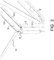
- First adjusting means 7 will be further elucidated in Figure 3 .
- First adjusting means 7 are placed close to a bottom corner of the frame, which bottom corner is formed by the angle between lower beam 2 and first upright 3 or the angle between lower beam 2 and second upright 5.
- First and second cords 10, 11 preferably lie at an angle here of about 30 to 60 degrees relative to lower beam 3.
- first and second cords 10, 11 are guided via an opening close to the centre of upper beam 4 to first adjusting means 7.
- upper beam 4 and lower beam 2 are preferably adjustable. This can be achieved by embodying both upper beam 4 and lower beam 2 as two parts for sliding into each other.
- first and second uprights 3, 5 are preferably height-adjustable. This can be achieved by embodying both the first and second uprights 3, 5 as two parts for sliding into each other.
- Figure 2 shows a second preferred embodiment of frame 100 according to the invention, wherein frame 100 is also provided with second coupling means for coupling the second device.
- the second coupling means operate in the same way as first coupling means but are connected via third and fourth cord 110, 111 to second adjusting means 107.
- the second coupling means are intended for coupling of a second device to a side B of frame 100 lying opposite side A.
- FIG 3 shows a further development of the first coupling means for coupling the device according to Figure 2 .
- the first coupling means comprise a first and second coupling element 8, 9
- Coupling element 8 is arranged in first upright 3.
- Coupling element 9 is arranged in second upright 5 and is not shown, but operates in the same way as coupling element 8.
- Coupling element 8 is connected via first cord 10 to first adjusting means 7.
- Coupling element 8 is configured for coupling to a first device 50, such as a support beam for a desk top.
- Both the first and the second upright 3, 5 are provided with a guide track configured to enclose respective coupling elements 8, 9 and to guide the respective coupling elements 8, 9 in the height.
- First and second uprights 3, 5 are preferably embodied as a profile in which the guide track is arranged.
- Figure 4 shows a further development of the first and second coupling means for coupling of a first and second device as according to Figure 2 .
- the second coupling means comprise a first and second coupling element 108, 109.
- Coupling element 108 is arranged in first upright 3.
- Coupling element 109 is arranged in second upright 5 and is not shown but operates in the same way as coupling element 108.
- coupling element 108 is connected via third cord 110 to second adjusting means 107.
- Coupling elements 108, 109 are configured for coupling to a second device such as a desk top.
- Second adjusting means 107 are preferably also placed close to a bottom corner of frame 100, which bottom corner is formed by the angle between lower beam 2 and first upright 3 or the angle between lower beam 2 and second upright 5.
- Third and fourth cords 110, 111 preferably lie at an angle here of about 30 to 60 degrees relative to lower beam 3. As a result third and fourth cords 110, 111 are guided via an opening close to the centre of upper beam 4 to second adjusting means 107.
- the first, second, third and/or fourth cables 10, 11, 110, 111 at least partially comprise a Bowden cable.
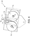
- Adjusting means 7, 107 comprise two constant-force springs 71, 72, wherein a first outer end of each constant-force spring 71, 72 is connected to the first and the second cord 10, 11 or the third and fourth cord 110, 111.
- the constant-force springs 71, 72 each comprise a rolled-up leaf spring.
- the leaf springs are placed in mirrored arrangement in a housing 73 such that the outer sides of the parts unrolled from the leaf springs are adjacent. Housing 73 is provided for this purpose with the two shafts 74, 75 on which force spring 71 and force spring 72 are respectively arranged.
- Adjusting means 7, 107 are provided with brakes 76, 77 which engage on constant-force springs 71, 72.
- Brakes 76, 77 can be operated via the first and/or second operating member. Brakes 76, 77 are for this purpose mutually connected (see Figure 6 ) by means of a brake cable (not shown) and the brake cable engages on the first and/or second operating member.
- Figure 5 shows the first or second adjusting means 7, 107 according to Figure 4 in loaded state, wherein the leaf springs of constant-force springs 71, 72 are at least partially unwound. Owing to the disposition of force springs 71, 72 the unwound parts of the leaf springs together form a straight leaf. Brakes 76 and 77 can be operated via a shared brake cable 78. Brakes 76, 77 are automatically released by spring 79 when brake cable 78 is not being operated.
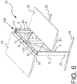
- FIG 6 shows an application of frame 100 according to Figure 2 in a desk 20 with a double top.
- Desk 20 is provided with the frame 100 according to the invention.
- Frame 100 is connected here at first and second beams 2, 4 to legs 21, 22 which are connected to feet 25, 26.
- Desk top 23 is connected via first and second coupling elements 8, 9 to frame 100 by means of support beams 50, 51 which form the first and second device.
- Desk top 24 is connected in the same way to frame 100 via third and fourth coupling elements 108, 109 (not shown).
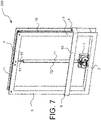
- Figure 7 shows a further embodiment of frame 200 according to the invention, wherein for instance a painting or screen can be hung on a flat vertical surface such as a wall via a first device 53.
- First device 53 is connected for this purpose to first and second coupling elements 8, 9.
- Adjusting means 7 are placed here close to the centre of lower beam 2.
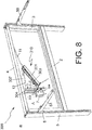
- Figure 8 shows an optimized embodiment of frame 300 according to the invention.
- the first adjusting means 7 are arranged for displacement along a first path in frame 300, and first and second cords 10;11 are connected at an angle ⁇ adjustable relative to the first path to first adjusting means 7.
- Frame 300 is provided for this purpose with a first guide channel 301.
- the housing of first adjusting means 7 is provided on either side with (corresponding) wheels 306.
- Placed on frame 300 are two pairs of parallel placed strips 304, wherein each pair encloses the wheels 306 placed on a side of the housing.
- Strips 304 define the first path.
- the first guide channel 301 is mounted rotatably on frame 300 directly or indirectly at a first outer end and extends from the first outer end substantially in the direction of the first path.
- first guide channel 301 The angle ⁇ between the longitudinal direction of first guide channel 301 and the first path is adjustable between preferably 45 and 90 degrees, for instance by means of a spindle (not shown) which can change the position of guide channel 301.
- First adjusting means 7 are connected to first and second cords 10;11 by means of a first guide element 303, wherein first guide element 303 is displaceable in guiding manner between the first and a second outer end of first guide channel 301.
- the first path is preferably vertical and the first side of first guide channel 301 is placed close to the centre of upper beam 4.
- Strips 304, first adjusting means 7, first guide element 303 and first guide channel 301 are preferably arranged between two parallel placed plates 307, one of which is shown. This combination forms a module 310 which can be mounted or detached in its entirety on or from frame 300.
- the first path need not per se be straight.
- the first path can for instance also form a part of a circular path or an elliptical path.
- the angle ⁇ between the longitudinal direction of first guide channel 301 and the first path is about 45 degrees, and in the shown embodiment is the minimal angle. In this position the pulling force exerted by adjusting means 7 on the first and second cords 10;11 is minimal. If in the shown embodiment the second side of guide channel 301 is displaced toward upper beam 4, the angle ⁇ between the longitudinal direction of first guide channel 301 and the first path also increases, and adjusting means 7 will displace in the direction of upper beam 4 so as to follow the guide channel 301. As this angle ⁇ increases, the pulling force exerted by adjusting means 7 on first and second cords 10;11 will also increase. The pulling force is maximal when the angle ⁇ nears 90 degrees.
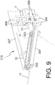
- Figure 9 shows module 310 for applying in frame 300 according to the invention.
- Module 310 comprises two parallel placed plates 307, one of which is not shown.
- Strips 304, the first adjusting means, first guide element 303 and first guide channel 301 are arranged between plates 307.
- First guide channel 301 is mounted rotatably by means of a pin-hole connection 302.
- the angle ⁇ between the longitudinal direction of first guide channel 301 and the first path nears 90 degrees in the shown figure.
- the pulling force exerted by adjusting means 7 on first and second cords 10;11 is approximately maximal in this position.
Landscapes
- Engineering & Computer Science (AREA)
- General Engineering & Computer Science (AREA)
- Mechanical Engineering (AREA)
- Tables And Desks Characterized By Structural Shape (AREA)
- Drawing Aids And Blackboards (AREA)
- Rehabilitation Tools (AREA)
Claims (20)
- Rechteckiger Rahmen (1, 100, 200, 300), welcher Rahmen (1 , 100, 200, 300) durch mindestens einen ersten senkrechten Rahmenstab (3), einen oberen waagerechten Rahmenstab (4), einen zweiten senkrechten Rahmenstab (5) und einen unteren waagerechten Rahmenstab (2) gebildet wird, wobei der Rahmen (1, 100, 200, 300) mit ersten Kopplungsmitteln versehen ist und der Rahmen (1, 100, 200, 300) zur Kopplung einer ersten Vorrichtung, wie z.B. ein Bildschirm, eine schwarze oder weiße Tafel oder ein Gemälde, mit einer ersten Seite (A) des Rahmens (1, 100, 200, 300) mittels des ersten Kopplungsmittels konfiguriert ist, wobei der Rahmen (1, 100, 200, 300) auch für eine einstellbare Platzierung der ersten Vorrichtung in der Höhe relativ zu dem Rahmen (1, 100, 200, 300) konfiguriert ist, wobei der Rahmen (1, 100, 200, 300) mit ersten Einstellmitteln (7) zum Einstellen der ersten Kopplungsmittel und eines ersten Betätigungselements zum Betätigen der ersten Einstellmittel (7) versehen ist, wobei das erste Kopplungsmittel ein erstes und ein zweites Kopplungselement (8, 9) umfasst, wobei das erste und das zweite Kopplungselement (8, 9) für eine gleichzeitige einstellbare Verschiebung auf im Wesentlichen die gleiche Höhe in jeweils dem ersten bzw. dem zweiten senkrechten Rahmenstab (3, 5) angeordnet sind und jeweils mittels einer ersten und zweiten Schnur (10, 11) mit den ersten Einstellmitteln (7) verbunden sind, dadurch gekennzeichnet, dass die ersten Einstellmittel (7) mindestens eine Konstantkraftfeder (71, 72) umfassen, wobei ein erstes äußeres Ende jeder Konstantkraftfeder (71, 72) sowohl mit der ersten als auch mit der zweiten Schnur (11) verbunden ist.
- Rahmen (1, 100, 200, 300) nach Anspruch 1, dadurch gekennzeichnet, dass der Rahmen (1, 100, 200, 300) auch für eine einstellbare Anordnung in der Höhe relativ zum Rahmen (1, 100, 200, 300) einer zweiten Vorrichtung, wie z.B. ein Bildschirm, eine schwarze oder weiße Tafel oder ein Gemälde, zur Kopplung mit einer zweiten Seite (B) des Rahmens (1, 100, 200, 300) konfiguriert ist, wobei der Rahmen (1, 100, 200, 300) mit zweiten Kopplungsmittel zum Koppeln der zweiten Vorrichtung, eines zweiten Einstellmittels (107) zum Einstellen der zweiten Kopplungsmittel und eines zweiten Betätigungselements zum Betätigen des zweiten Einstellmittels (107) versehen ist, wobei die zweiten Kopplungsmittel ein drittes und viertes Kopplungselement (108, 109) umfassen, wobei die dritten und vierten Kopplungselemente (108, 109) für eine gleichzeitige einstellbare Verschiebung auf im Wesentlichen die gleiche Höhe in jeweils dem ersten bzw. zweiten senkrechten Rahmenstab (3, 5) angeordnet sind und jeweils mittels einer dritten und vierten Schnur (110, 111) mit dem zweiten Einstellmittel (107) verbunden sind, wobei die zweiten Einstellmittel (107) mindestens eine Konstantkraftfeder (71 , 72) aufweisen, wobei ein erstes äußeres Ende jeder Konstantkraftfeder (71 , 72) der zweiten Einstellmittel (107) sowohl mit der dritten als auch mit der vierten Schnur (111) verbunden sind.
- Rahmen (1, 100, 200, 300) nach Anspruch 1 oder 2, wobei die ersten und/oder zweiten Einstellmittel (7, 107) ein Gehäuse (73) umfassen, das im Wesentlichen jede Konstantkraftfeder (71, 72) im unbelasteten Zustand umfasst, wobei ein zweites äußeres Ende jeder Konstantkraftfeder (71, 72) fest mit dem Gehäuse (73) verbunden ist.
- Rahmen (1, 100, 200, 300) nach Anspruch 1, 2 oder 3, wobei jede Konstantkraftfeder (71, 72) mit einer Bremse (76, 77) versehen ist, die an der Konstantkraftfeder (71, 72) angreift, und wobei die Bremse (76, 77) über das erste und/oder zweite Betätigungselement betätigt werden kann.
- Rahmen (1, 100, 200, 300) nach Anspruch 4, wobei die Bremsen (76, 77) jeder Konstantkraftfeder (71, 72) mittels eines Bremskabels (78) miteinander verbunden sind und das erste und/oder zweite Betätigungselement an dem Bremskabel (78) angreift.
- Rahmen (1, 100, 200, 300) nach einem der Ansprüche 3-5, wobei das erste und/oder zweite Einstellmittel (7, 107) eine Anzahl von Paaren von Konstantkraftfedern (71, 72) umfasst, wobei jede Kraftfeder eine aufgerollte Blattfeder umfasst und jedes Paar Blattfedern in gespiegelter Anordnung in dem Rahmen (1, 100, 200, 300) so angeordnet ist, dass die Außenseiten der abgerollten Teile jedes Paares von Blattfedern aneinander grenzen.
- Rahmen (1, 100, 200, 300) nach Anspruch 6, wobei das erste und/oder zweite Einstellmittel (7, 107) ein Paar Konstantkraftfedern (71, 72) umfasst.
- Rahmen (1, 100) nach einem der Ansprüche 1-7, wobei die ersten Einstellmittel (7) nahe einer unteren Ecke des Rahmens (1, 100, 200, 300) angeordnet sind und die ersten und zweiten Schnüre (10, 11) mit den ersten Einstellmitteln (7) in einem Winkel von etwa 30 bis 60 Grad relativ zum unteren Balken (2) verbunden sind.
- Rahmen (1, 100) nach einem der Ansprüche 2-8, wobei die zweiten Einstellmittel (107) nahe einer unteren Ecke des Rahmens (1, 100, 200, 300) angeordnet sind und die dritte und vierte Schnur (110, 111) mit den zweiten Einstellmitteln (107) in einem Winkel von etwa 30 bis 60 Grad relativ zum unteren Balken (2) verbunden sind.
- Rahmen (1, 100) nach Anspruch 9, wobei das erste und das zweite Einstellmittel (107) nahe an verschiedenen unteren Ecken angeordnet sind.
- Rahmen (1, 100, 200, 300) wie in einem der Ansprüche 3-7 beansprucht, wobei die ersten Einstellmittel (7) zur Verschiebung entlang eines ersten Weges in dem Rahmen (1, 100, 200, 300) angeordnet sind und die ersten und zweiten Schnüre (10, 11) mit den ersten Einstellmitteln (7) in einem Winkel (α) verbunden sind, der relativ zum ersten Weg einstellbar ist.
- Rahmen (1, 100, 200, 300) nach Anspruch 11, wobei der Rahmen (1 , 100, 200, 300) mit einem ersten Führungskanal (301) versehen ist, der drehbar an einem ersten äußeren Ende an dem Rahmen (1 , 100, 200, 300) montiert ist und der sich von dem ersten äußeren Ende im Wesentlichen in Richtung des ersten Weges erstreckt, wobei der Winkel (α) zwischen der Längsrichtung des ersten Führungskanals (301) und dem ersten Weg einstellbar ist und die ersten Einstellmittel (7) mit den ersten und zweiten Schnüren (10, 11) mittels eines ersten Führungselements (303) verbunden sind, wobei das erste Führungselement (303) in führender Weise zwischen dem ersten und einem zweiten äußeren Ende des ersten Führungskanals (301) verschiebbar ist.
- Rahmen (1, 100, 200, 300) wie in einem der Ansprüche 3-7, 11 oder 12 beansprucht, wobei die zweiten Einstellmittel (107) zur Verschiebung entlang eines zweiten Weges im Rahmen (1, 100, 200, 300) angeordnet sind und die dritte und vierte Schnur (110, 111) mit den zweiten Verschiebungsmitteln (107) in einem Winkel (α) verbunden sind, der relativ zum zweiten Weg einstellbar ist.
- Rahmen (1, 100, 200, 300) nach Anspruch 13, wobei der Rahmen (1, 100, 200, 300) mit einem zweiten Führungskanal versehen ist, der drehbar an einem ersten äußeren Ende an dem Rahmen (1, 100, 200, 300) montiert ist und der sich von dem ersten äußeren Ende im Wesentlichen in Richtung des zweiten Weges erstreckt, wobei der Winkel zwischen der Längsrichtung des zweiten Führungskanals und der zweiten Bahn einstellbar ist und die zweiten Einstellmittel (107) mit dem dritten und vierten Schnüren (110, 111) mittels eines zweiten Führungselements verbunden sind, wobei das zweite Führungselement zwischen dem ersten und einem zweiten äußeren Ende des zweiten Führungskanals führend verschiebbar ist.
- Rahmen (1, 200) nach einem der Ansprüche 1-6, wobei das erste Kopplungselement (10) und das zweite Kopplungselement (11) mittels eines Verbindungselements (53) miteinander verbunden sind.
- Rahmen (1, 200) nach Anspruch 15, wobei die ersten Einstellmittel (7) nahe der Mitte des unteren waagerechten Rahmenstabs (2) angeordnet sind.
- Rahmen (1, 100, 200, 300) nach einem der vorstehenden Ansprüche, wobei der obere waagerechte Rahmenstab (4) und der untere waagerechte Rahmenstab (2) in der Länge verstellbar sind.
- Rahmen (1, 100, 200, 300) nach einem der vorstehenden Ansprüche, wobei die erste, zweite, dritte und/oder vierte Schnur (10, 11, 110, 111) einen Bowdenzug umfasst.
- Rahmen (1, 100, 200, 300) wie in einem der vorstehenden Ansprüche beansprucht, wobei die ersten und zweiten senkrechte Rahmenstäbe (3, 5) höhenverstellbar sind.
- Rahmen (1, 100, 200, 300) nach einem der vorstehenden Ansprüche, wobei die erste und/oder zweite Seite (A, B) des ersten und zweiten senkrechten Rahmenstabs (3, 5) mit einer Führungsschiene (11) versehen sind, die so konfiguriert ist, dass sie ein Kopplungselement (8, 9, 108, 109) umschließt und das Kopplungselement (8, 9, 108, 109) vertikal führt.
Priority Applications (1)
| Application Number | Priority Date | Filing Date | Title |
|---|---|---|---|
| PL16734475T PL3282893T3 (pl) | 2015-04-17 | 2016-04-14 | Rama prostokątna z regulacją wysokości dla pierwszego i/lub drugiego urządzenia do sprzęgania z ramą |
Applications Claiming Priority (2)
| Application Number | Priority Date | Filing Date | Title |
|---|---|---|---|
| NL2014654A NL2014654B1 (nl) | 2015-04-17 | 2015-04-17 | Rechthoekig frame met hoogte instelling voor een aan het frame te koppelen eerste en/of tweede inrichting. |
| PCT/NL2016/050260 WO2016167656A2 (en) | 2015-04-17 | 2016-04-14 | Rectangular frame with height adjustment for a first and/or second device for coupling to the frame |
Publications (2)
| Publication Number | Publication Date |
|---|---|
| EP3282893A2 EP3282893A2 (de) | 2018-02-21 |
| EP3282893B1 true EP3282893B1 (de) | 2020-10-21 |
Family
ID=56322262
Family Applications (1)
| Application Number | Title | Priority Date | Filing Date |
|---|---|---|---|
| EP16734475.3A Active EP3282893B1 (de) | 2015-04-17 | 2016-04-14 | Rechteckiger rahmen mit höhenverstellung für eine erste und/oder zweite vorrichtung zur ankopplung an den rahmen |
Country Status (9)
| Country | Link |
|---|---|
| US (1) | US20180092456A1 (de) |
| EP (1) | EP3282893B1 (de) |
| JP (1) | JP2018516721A (de) |
| CN (1) | CN107635434A (de) |
| AU (1) | AU2016247420A1 (de) |
| CA (1) | CA2982256A1 (de) |
| NL (1) | NL2014654B1 (de) |
| PL (1) | PL3282893T3 (de) |
| WO (1) | WO2016167656A2 (de) |
Families Citing this family (3)
| Publication number | Priority date | Publication date | Assignee | Title |
|---|---|---|---|---|
| ITUB201613724U1 (it) * | 2016-02-01 | 2017-08-01 | Terry Store Age S P A | Armadio modulare componibile in materiale plastico |
| CN109965569A (zh) * | 2018-12-07 | 2019-07-05 | 马肯国际有限公司 | 一种可升降组合办公桌 |
| US20250305800A1 (en) * | 2022-09-30 | 2025-10-02 | Israel S. Fried | Display board ballistic shield |
Family Cites Families (11)
| Publication number | Priority date | Publication date | Assignee | Title |
|---|---|---|---|---|
| US3188986A (en) * | 1962-04-09 | 1965-06-15 | Brunswick Corp | Bedside table |
| GB1005570A (en) * | 1962-05-28 | 1965-09-22 | Hendrik Wolters | Improvements in or relating to supporting constructions for a blackboard, projectionscreen or like article |
| MXPA04012124A (es) * | 2002-06-07 | 2005-04-28 | Krueger Int Inc | Mesa de altura ajustable, de giro rapido de manivela. |
| CN2564004Y (zh) * | 2002-09-04 | 2003-08-06 | 孟凡刚 | 可随遇平衡的升降式桌体 |
| CN200972794Y (zh) * | 2006-10-26 | 2007-11-07 | 呈杰股份有限公司 | 显示器升降支撑架的改良结构 |
| GB2501054A (en) * | 2012-01-18 | 2013-10-16 | Icon Office Design Ltd | A support unit for supporting platform for a computer or keyboard onto an upright body |
| DE102012019747B4 (de) * | 2012-10-09 | 2020-12-03 | B. Ketterer Söhne GmbH & Co. KG | Möbel mit einer vertikal verstellbaren Auflageplatte |
| US20140196553A1 (en) * | 2013-01-15 | 2014-07-17 | Johan Rinman | Adjustable object |
| CN104095393B (zh) * | 2013-04-12 | 2016-03-16 | 再兴电子(深圳)有限公司 | 升降桌 |
| CN104214491B (zh) * | 2013-05-29 | 2017-08-04 | 泰州市创新电子有限公司 | 一种可调升降承载力的拉压簧式显示屏恒力升降支撑架 |
| CN106641641B (zh) * | 2016-12-22 | 2018-09-07 | 泰州市创新电子有限公司 | 一种可调定力升降装置及其显示器 |
-
2015
- 2015-04-17 NL NL2014654A patent/NL2014654B1/nl not_active IP Right Cessation
-
2016
- 2016-04-14 AU AU2016247420A patent/AU2016247420A1/en not_active Abandoned
- 2016-04-14 JP JP2018506073A patent/JP2018516721A/ja not_active Abandoned
- 2016-04-14 PL PL16734475T patent/PL3282893T3/pl unknown
- 2016-04-14 CA CA2982256A patent/CA2982256A1/en not_active Abandoned
- 2016-04-14 WO PCT/NL2016/050260 patent/WO2016167656A2/en not_active Ceased
- 2016-04-14 CN CN201680025428.9A patent/CN107635434A/zh active Pending
- 2016-04-14 EP EP16734475.3A patent/EP3282893B1/de active Active
- 2016-04-14 US US15/566,804 patent/US20180092456A1/en not_active Abandoned
Non-Patent Citations (1)
| Title |
|---|
| None * |
Also Published As
| Publication number | Publication date |
|---|---|
| US20180092456A1 (en) | 2018-04-05 |
| WO2016167656A2 (en) | 2016-10-20 |
| NL2014654B1 (nl) | 2017-01-25 |
| NL2014654A (nl) | 2016-10-20 |
| WO2016167656A3 (en) | 2017-01-12 |
| CN107635434A (zh) | 2018-01-26 |
| CA2982256A1 (en) | 2016-10-20 |
| EP3282893A2 (de) | 2018-02-21 |
| AU2016247420A1 (en) | 2017-11-09 |
| PL3282893T3 (pl) | 2021-01-25 |
| JP2018516721A (ja) | 2018-06-28 |
Similar Documents
| Publication | Publication Date | Title |
|---|---|---|
| AU2013206330B2 (en) | Curtain | |
| US20120162760A1 (en) | Portable Projection Screen | |
| EP3282893B1 (de) | Rechteckiger rahmen mit höhenverstellung für eine erste und/oder zweite vorrichtung zur ankopplung an den rahmen | |
| US20160138330A1 (en) | Cord-winding device for a blind assembly having no pull cord | |
| DE102009041285B4 (de) | Höhenpositioniervorrichtung für Präsentationssysteme | |
| WO2014024214A8 (en) | Control and movement device for mosquito screens, curtains and the like | |
| JP2014152601A (ja) | コードレスブラインドアセンブリ | |
| KR20130005650U (ko) | 가변형 파티션 및 이를 사용한 테이블 | |
| US20110247766A1 (en) | Control system for cordless blinds | |
| JP5510918B2 (ja) | テーブル | |
| KR101745417B1 (ko) | 접이식 파티션 및 이를 구비한 테이블 | |
| GB2162626A (en) | Support means for sun tanning canopies | |
| KR101216744B1 (ko) | 책상의 상판 높낮이 조절장치 | |
| CN201845166U (zh) | 改进的可携式投影幕结构 | |
| CN204677095U (zh) | 一种无绳窗帘 | |
| KR101356669B1 (ko) | 모니터 승강장치 및 이를 구비한 책상 | |
| CN210573160U (zh) | 一种室外实验课程投影装置 | |
| US20160115734A1 (en) | Window shade linking device | |
| KR20080063685A (ko) | 디스플레이 기기 및 디스플레이 기기의 위치 조절을 위한탄성력 조절 장치 | |
| CN203676649U (zh) | 一种新型护栏 | |
| CN207435776U (zh) | 一种电动晾衣机及其伸缩托架 | |
| CN215267456U (zh) | 一种安装支架的传感器线缆过线装置 | |
| CA2299030A1 (en) | Cord control device for a venetian blind to control raising and lowering of the slats | |
| AU2019100196A4 (en) | Ready-to-stop elevation carrier platform | |
| KR200180224Y1 (ko) | 상하높이조절가능한붙박이칠판 |
Legal Events
| Date | Code | Title | Description |
|---|---|---|---|
| STAA | Information on the status of an ep patent application or granted ep patent |
Free format text: STATUS: THE INTERNATIONAL PUBLICATION HAS BEEN MADE |
|
| PUAI | Public reference made under article 153(3) epc to a published international application that has entered the european phase |
Free format text: ORIGINAL CODE: 0009012 |
|
| STAA | Information on the status of an ep patent application or granted ep patent |
Free format text: STATUS: REQUEST FOR EXAMINATION WAS MADE |
|
| 17P | Request for examination filed |
Effective date: 20171113 |
|
| AK | Designated contracting states |
Kind code of ref document: A2 Designated state(s): AL AT BE BG CH CY CZ DE DK EE ES FI FR GB GR HR HU IE IS IT LI LT LU LV MC MK MT NL NO PL PT RO RS SE SI SK SM TR |
|
| AX | Request for extension of the european patent |
Extension state: BA ME |
|
| DAV | Request for validation of the european patent (deleted) | ||
| DAX | Request for extension of the european patent (deleted) | ||
| GRAP | Despatch of communication of intention to grant a patent |
Free format text: ORIGINAL CODE: EPIDOSNIGR1 |
|
| STAA | Information on the status of an ep patent application or granted ep patent |
Free format text: STATUS: GRANT OF PATENT IS INTENDED |
|
| INTG | Intention to grant announced |
Effective date: 20200508 |
|
| GRAS | Grant fee paid |
Free format text: ORIGINAL CODE: EPIDOSNIGR3 |
|
| GRAA | (expected) grant |
Free format text: ORIGINAL CODE: 0009210 |
|
| STAA | Information on the status of an ep patent application or granted ep patent |
Free format text: STATUS: THE PATENT HAS BEEN GRANTED |
|
| AK | Designated contracting states |
Kind code of ref document: B1 Designated state(s): AL AT BE BG CH CY CZ DE DK EE ES FI FR GB GR HR HU IE IS IT LI LT LU LV MC MK MT NL NO PL PT RO RS SE SI SK SM TR |
|
| REG | Reference to a national code |
Ref country code: GB Ref legal event code: FG4D |
|
| REG | Reference to a national code |
Ref country code: CH Ref legal event code: EP |
|
| REG | Reference to a national code |
Ref country code: DE Ref legal event code: R096 Ref document number: 602016046226 Country of ref document: DE |
|
| REG | Reference to a national code |
Ref country code: IE Ref legal event code: FG4D |
|
| REG | Reference to a national code |
Ref country code: AT Ref legal event code: REF Ref document number: 1324940 Country of ref document: AT Kind code of ref document: T Effective date: 20201115 |
|
| REG | Reference to a national code |
Ref country code: NL Ref legal event code: FP |
|
| REG | Reference to a national code |
Ref country code: AT Ref legal event code: MK05 Ref document number: 1324940 Country of ref document: AT Kind code of ref document: T Effective date: 20201021 |
|
| PG25 | Lapsed in a contracting state [announced via postgrant information from national office to epo] |
Ref country code: FI Free format text: LAPSE BECAUSE OF FAILURE TO SUBMIT A TRANSLATION OF THE DESCRIPTION OR TO PAY THE FEE WITHIN THE PRESCRIBED TIME-LIMIT Effective date: 20201021 Ref country code: GR Free format text: LAPSE BECAUSE OF FAILURE TO SUBMIT A TRANSLATION OF THE DESCRIPTION OR TO PAY THE FEE WITHIN THE PRESCRIBED TIME-LIMIT Effective date: 20210122 Ref country code: NO Free format text: LAPSE BECAUSE OF FAILURE TO SUBMIT A TRANSLATION OF THE DESCRIPTION OR TO PAY THE FEE WITHIN THE PRESCRIBED TIME-LIMIT Effective date: 20210121 Ref country code: RS Free format text: LAPSE BECAUSE OF FAILURE TO SUBMIT A TRANSLATION OF THE DESCRIPTION OR TO PAY THE FEE WITHIN THE PRESCRIBED TIME-LIMIT Effective date: 20201021 Ref country code: PT Free format text: LAPSE BECAUSE OF FAILURE TO SUBMIT A TRANSLATION OF THE DESCRIPTION OR TO PAY THE FEE WITHIN THE PRESCRIBED TIME-LIMIT Effective date: 20210222 |
|
| REG | Reference to a national code |
Ref country code: LT Ref legal event code: MG4D |
|
| PG25 | Lapsed in a contracting state [announced via postgrant information from national office to epo] |
Ref country code: ES Free format text: LAPSE BECAUSE OF FAILURE TO SUBMIT A TRANSLATION OF THE DESCRIPTION OR TO PAY THE FEE WITHIN THE PRESCRIBED TIME-LIMIT Effective date: 20201021 Ref country code: AT Free format text: LAPSE BECAUSE OF FAILURE TO SUBMIT A TRANSLATION OF THE DESCRIPTION OR TO PAY THE FEE WITHIN THE PRESCRIBED TIME-LIMIT Effective date: 20201021 Ref country code: BG Free format text: LAPSE BECAUSE OF FAILURE TO SUBMIT A TRANSLATION OF THE DESCRIPTION OR TO PAY THE FEE WITHIN THE PRESCRIBED TIME-LIMIT Effective date: 20210121 Ref country code: IS Free format text: LAPSE BECAUSE OF FAILURE TO SUBMIT A TRANSLATION OF THE DESCRIPTION OR TO PAY THE FEE WITHIN THE PRESCRIBED TIME-LIMIT Effective date: 20210221 Ref country code: LV Free format text: LAPSE BECAUSE OF FAILURE TO SUBMIT A TRANSLATION OF THE DESCRIPTION OR TO PAY THE FEE WITHIN THE PRESCRIBED TIME-LIMIT Effective date: 20201021 Ref country code: SE Free format text: LAPSE BECAUSE OF FAILURE TO SUBMIT A TRANSLATION OF THE DESCRIPTION OR TO PAY THE FEE WITHIN THE PRESCRIBED TIME-LIMIT Effective date: 20201021 |
|
| PG25 | Lapsed in a contracting state [announced via postgrant information from national office to epo] |
Ref country code: HR Free format text: LAPSE BECAUSE OF FAILURE TO SUBMIT A TRANSLATION OF THE DESCRIPTION OR TO PAY THE FEE WITHIN THE PRESCRIBED TIME-LIMIT Effective date: 20201021 |
|
| REG | Reference to a national code |
Ref country code: DE Ref legal event code: R097 Ref document number: 602016046226 Country of ref document: DE |
|
| PG25 | Lapsed in a contracting state [announced via postgrant information from national office to epo] |
Ref country code: LT Free format text: LAPSE BECAUSE OF FAILURE TO SUBMIT A TRANSLATION OF THE DESCRIPTION OR TO PAY THE FEE WITHIN THE PRESCRIBED TIME-LIMIT Effective date: 20201021 Ref country code: SM Free format text: LAPSE BECAUSE OF FAILURE TO SUBMIT A TRANSLATION OF THE DESCRIPTION OR TO PAY THE FEE WITHIN THE PRESCRIBED TIME-LIMIT Effective date: 20201021 Ref country code: CZ Free format text: LAPSE BECAUSE OF FAILURE TO SUBMIT A TRANSLATION OF THE DESCRIPTION OR TO PAY THE FEE WITHIN THE PRESCRIBED TIME-LIMIT Effective date: 20201021 Ref country code: EE Free format text: LAPSE BECAUSE OF FAILURE TO SUBMIT A TRANSLATION OF THE DESCRIPTION OR TO PAY THE FEE WITHIN THE PRESCRIBED TIME-LIMIT Effective date: 20201021 Ref country code: SK Free format text: LAPSE BECAUSE OF FAILURE TO SUBMIT A TRANSLATION OF THE DESCRIPTION OR TO PAY THE FEE WITHIN THE PRESCRIBED TIME-LIMIT Effective date: 20201021 Ref country code: RO Free format text: LAPSE BECAUSE OF FAILURE TO SUBMIT A TRANSLATION OF THE DESCRIPTION OR TO PAY THE FEE WITHIN THE PRESCRIBED TIME-LIMIT Effective date: 20201021 |
|
| PLBE | No opposition filed within time limit |
Free format text: ORIGINAL CODE: 0009261 |
|
| STAA | Information on the status of an ep patent application or granted ep patent |
Free format text: STATUS: NO OPPOSITION FILED WITHIN TIME LIMIT |
|
| PG25 | Lapsed in a contracting state [announced via postgrant information from national office to epo] |
Ref country code: DK Free format text: LAPSE BECAUSE OF FAILURE TO SUBMIT A TRANSLATION OF THE DESCRIPTION OR TO PAY THE FEE WITHIN THE PRESCRIBED TIME-LIMIT Effective date: 20201021 |
|
| 26N | No opposition filed |
Effective date: 20210722 |
|
| PG25 | Lapsed in a contracting state [announced via postgrant information from national office to epo] |
Ref country code: IT Free format text: LAPSE BECAUSE OF FAILURE TO SUBMIT A TRANSLATION OF THE DESCRIPTION OR TO PAY THE FEE WITHIN THE PRESCRIBED TIME-LIMIT Effective date: 20201021 Ref country code: AL Free format text: LAPSE BECAUSE OF FAILURE TO SUBMIT A TRANSLATION OF THE DESCRIPTION OR TO PAY THE FEE WITHIN THE PRESCRIBED TIME-LIMIT Effective date: 20201021 |
|
| PG25 | Lapsed in a contracting state [announced via postgrant information from national office to epo] |
Ref country code: MC Free format text: LAPSE BECAUSE OF FAILURE TO SUBMIT A TRANSLATION OF THE DESCRIPTION OR TO PAY THE FEE WITHIN THE PRESCRIBED TIME-LIMIT Effective date: 20201021 Ref country code: SI Free format text: LAPSE BECAUSE OF FAILURE TO SUBMIT A TRANSLATION OF THE DESCRIPTION OR TO PAY THE FEE WITHIN THE PRESCRIBED TIME-LIMIT Effective date: 20201021 |
|
| PG25 | Lapsed in a contracting state [announced via postgrant information from national office to epo] |
Ref country code: LU Free format text: LAPSE BECAUSE OF NON-PAYMENT OF DUE FEES Effective date: 20210414 |
|
| PG25 | Lapsed in a contracting state [announced via postgrant information from national office to epo] |
Ref country code: CH Free format text: LAPSE BECAUSE OF NON-PAYMENT OF DUE FEES Effective date: 20210430 Ref country code: LI Free format text: LAPSE BECAUSE OF NON-PAYMENT OF DUE FEES Effective date: 20210430 |
|
| PG25 | Lapsed in a contracting state [announced via postgrant information from national office to epo] |
Ref country code: IE Free format text: LAPSE BECAUSE OF NON-PAYMENT OF DUE FEES Effective date: 20210414 |
|
| PG25 | Lapsed in a contracting state [announced via postgrant information from national office to epo] |
Ref country code: IS Free format text: LAPSE BECAUSE OF FAILURE TO SUBMIT A TRANSLATION OF THE DESCRIPTION OR TO PAY THE FEE WITHIN THE PRESCRIBED TIME-LIMIT Effective date: 20210221 |
|
| PG25 | Lapsed in a contracting state [announced via postgrant information from national office to epo] |
Ref country code: HU Free format text: LAPSE BECAUSE OF FAILURE TO SUBMIT A TRANSLATION OF THE DESCRIPTION OR TO PAY THE FEE WITHIN THE PRESCRIBED TIME-LIMIT; INVALID AB INITIO Effective date: 20160414 |
|
| PG25 | Lapsed in a contracting state [announced via postgrant information from national office to epo] |
Ref country code: CY Free format text: LAPSE BECAUSE OF FAILURE TO SUBMIT A TRANSLATION OF THE DESCRIPTION OR TO PAY THE FEE WITHIN THE PRESCRIBED TIME-LIMIT Effective date: 20201021 |
|
| PGFP | Annual fee paid to national office [announced via postgrant information from national office to epo] |
Ref country code: NL Payment date: 20240319 Year of fee payment: 9 |
|
| PG25 | Lapsed in a contracting state [announced via postgrant information from national office to epo] |
Ref country code: MK Free format text: LAPSE BECAUSE OF FAILURE TO SUBMIT A TRANSLATION OF THE DESCRIPTION OR TO PAY THE FEE WITHIN THE PRESCRIBED TIME-LIMIT Effective date: 20201021 |
|
| PGFP | Annual fee paid to national office [announced via postgrant information from national office to epo] |
Ref country code: GB Payment date: 20240319 Year of fee payment: 9 |
|
| PGFP | Annual fee paid to national office [announced via postgrant information from national office to epo] |
Ref country code: PL Payment date: 20240320 Year of fee payment: 9 Ref country code: FR Payment date: 20240319 Year of fee payment: 9 Ref country code: BE Payment date: 20240319 Year of fee payment: 9 |
|
| PGFP | Annual fee paid to national office [announced via postgrant information from national office to epo] |
Ref country code: DE Payment date: 20240319 Year of fee payment: 9 |
|
| PGFP | Annual fee paid to national office [announced via postgrant information from national office to epo] |
Ref country code: TR Payment date: 20240405 Year of fee payment: 9 |
|
| PG25 | Lapsed in a contracting state [announced via postgrant information from national office to epo] |
Ref country code: MT Free format text: LAPSE BECAUSE OF FAILURE TO SUBMIT A TRANSLATION OF THE DESCRIPTION OR TO PAY THE FEE WITHIN THE PRESCRIBED TIME-LIMIT Effective date: 20201021 |
|
| REG | Reference to a national code |
Ref country code: DE Ref legal event code: R119 Ref document number: 602016046226 Country of ref document: DE |
|
| REG | Reference to a national code |
Ref country code: NL Ref legal event code: MM Effective date: 20250501 |
|
| GBPC | Gb: european patent ceased through non-payment of renewal fee |
Effective date: 20250414 |
|
| REG | Reference to a national code |
Ref country code: BE Ref legal event code: MM Effective date: 20250430 |
|
| PG25 | Lapsed in a contracting state [announced via postgrant information from national office to epo] |
Ref country code: DE Free format text: LAPSE BECAUSE OF NON-PAYMENT OF DUE FEES Effective date: 20251104 |
|
| PG25 | Lapsed in a contracting state [announced via postgrant information from national office to epo] |
Ref country code: GB Free format text: LAPSE BECAUSE OF NON-PAYMENT OF DUE FEES Effective date: 20250414 |
|
| PG25 | Lapsed in a contracting state [announced via postgrant information from national office to epo] |
Ref country code: NL Free format text: LAPSE BECAUSE OF NON-PAYMENT OF DUE FEES Effective date: 20250501 Ref country code: FR Free format text: LAPSE BECAUSE OF NON-PAYMENT OF DUE FEES Effective date: 20250430 |
|
| PG25 | Lapsed in a contracting state [announced via postgrant information from national office to epo] |
Ref country code: BE Free format text: LAPSE BECAUSE OF NON-PAYMENT OF DUE FEES Effective date: 20250430 |