EP3282237A1 - Leak detection system for objects enclosing rooms and coupling areas between same and associated method - Google Patents
Leak detection system for objects enclosing rooms and coupling areas between same and associated method Download PDFInfo
- Publication number
- EP3282237A1 EP3282237A1 EP17186247.7A EP17186247A EP3282237A1 EP 3282237 A1 EP3282237 A1 EP 3282237A1 EP 17186247 A EP17186247 A EP 17186247A EP 3282237 A1 EP3282237 A1 EP 3282237A1
- Authority
- EP
- European Patent Office
- Prior art keywords
- leakage
- monitoring
- pipe
- sensor
- monitoring system
- Prior art date
- Legal status (The legal status is an assumption and is not a legal conclusion. Google has not performed a legal analysis and makes no representation as to the accuracy of the status listed.)
- Withdrawn
Links
- 230000008878 coupling Effects 0.000 title claims description 12
- 238000010168 coupling process Methods 0.000 title claims description 12
- 238000005859 coupling reaction Methods 0.000 title claims description 12
- 238000000034 method Methods 0.000 title description 9
- 238000001514 detection method Methods 0.000 title description 7
- 238000012544 monitoring process Methods 0.000 claims abstract description 48
- 230000008859 change Effects 0.000 claims description 19
- 238000007789 sealing Methods 0.000 claims description 5
- 238000004519 manufacturing process Methods 0.000 claims description 2
- 238000011156 evaluation Methods 0.000 abstract description 18
- 239000000463 material Substances 0.000 description 15
- 238000005259 measurement Methods 0.000 description 13
- 239000012530 fluid Substances 0.000 description 7
- 239000002184 metal Substances 0.000 description 7
- 230000003449 preventive effect Effects 0.000 description 7
- 239000004033 plastic Substances 0.000 description 5
- 229920003023 plastic Polymers 0.000 description 5
- 230000001133 acceleration Effects 0.000 description 4
- 239000004020 conductor Substances 0.000 description 4
- 238000010586 diagram Methods 0.000 description 4
- 238000012545 processing Methods 0.000 description 4
- 230000032683 aging Effects 0.000 description 3
- 230000000694 effects Effects 0.000 description 3
- 230000006870 function Effects 0.000 description 3
- 238000012360 testing method Methods 0.000 description 3
- 101100478674 Mus musculus Stk3 gene Proteins 0.000 description 2
- 238000004873 anchoring Methods 0.000 description 2
- 239000003990 capacitor Substances 0.000 description 2
- 239000004918 carbon fiber reinforced polymer Substances 0.000 description 2
- 239000004744 fabric Substances 0.000 description 2
- 230000002431 foraging effect Effects 0.000 description 2
- 238000009434 installation Methods 0.000 description 2
- 238000012806 monitoring device Methods 0.000 description 2
- 230000007704 transition Effects 0.000 description 2
- 229920000049 Carbon (fiber) Polymers 0.000 description 1
- 230000005540 biological transmission Effects 0.000 description 1
- 238000009529 body temperature measurement Methods 0.000 description 1
- 239000004917 carbon fiber Substances 0.000 description 1
- 239000002131 composite material Substances 0.000 description 1
- 239000000470 constituent Substances 0.000 description 1
- 238000010276 construction Methods 0.000 description 1
- 238000013461 design Methods 0.000 description 1
- 238000005553 drilling Methods 0.000 description 1
- 230000007613 environmental effect Effects 0.000 description 1
- 230000003628 erosive effect Effects 0.000 description 1
- 239000011152 fibreglass Substances 0.000 description 1
- 239000007789 gas Substances 0.000 description 1
- 238000002847 impedance measurement Methods 0.000 description 1
- 230000001939 inductive effect Effects 0.000 description 1
- 239000007788 liquid Substances 0.000 description 1
- 230000004807 localization Effects 0.000 description 1
- 230000007774 longterm Effects 0.000 description 1
- VNWKTOKETHGBQD-UHFFFAOYSA-N methane Chemical compound C VNWKTOKETHGBQD-UHFFFAOYSA-N 0.000 description 1
- 229910052755 nonmetal Inorganic materials 0.000 description 1
- 239000002985 plastic film Substances 0.000 description 1
- 238000003672 processing method Methods 0.000 description 1
- 230000035945 sensitivity Effects 0.000 description 1
- 230000001953 sensory effect Effects 0.000 description 1
- 239000011257 shell material Substances 0.000 description 1
- 230000002123 temporal effect Effects 0.000 description 1
- 238000012800 visualization Methods 0.000 description 1
- 238000003466 welding Methods 0.000 description 1
Images


Classifications
-
- G—PHYSICS
- G01—MEASURING; TESTING
- G01M—TESTING STATIC OR DYNAMIC BALANCE OF MACHINES OR STRUCTURES; TESTING OF STRUCTURES OR APPARATUS, NOT OTHERWISE PROVIDED FOR
- G01M3/00—Investigating fluid-tightness of structures
- G01M3/02—Investigating fluid-tightness of structures by using fluid or vacuum
- G01M3/04—Investigating fluid-tightness of structures by using fluid or vacuum by detecting the presence of fluid at the leakage point
- G01M3/16—Investigating fluid-tightness of structures by using fluid or vacuum by detecting the presence of fluid at the leakage point using electric detection means
- G01M3/18—Investigating fluid-tightness of structures by using fluid or vacuum by detecting the presence of fluid at the leakage point using electric detection means for pipes, cables or tubes; for pipe joints or seals; for valves; for welds; for containers, e.g. radiators
- G01M3/183—Investigating fluid-tightness of structures by using fluid or vacuum by detecting the presence of fluid at the leakage point using electric detection means for pipes, cables or tubes; for pipe joints or seals; for valves; for welds; for containers, e.g. radiators for pipe joints or seals
-
- G—PHYSICS
- G01—MEASURING; TESTING
- G01M—TESTING STATIC OR DYNAMIC BALANCE OF MACHINES OR STRUCTURES; TESTING OF STRUCTURES OR APPARATUS, NOT OTHERWISE PROVIDED FOR
- G01M3/00—Investigating fluid-tightness of structures
- G01M3/02—Investigating fluid-tightness of structures by using fluid or vacuum
- G01M3/04—Investigating fluid-tightness of structures by using fluid or vacuum by detecting the presence of fluid at the leakage point
- G01M3/16—Investigating fluid-tightness of structures by using fluid or vacuum by detecting the presence of fluid at the leakage point using electric detection means
- G01M3/18—Investigating fluid-tightness of structures by using fluid or vacuum by detecting the presence of fluid at the leakage point using electric detection means for pipes, cables or tubes; for pipe joints or seals; for valves; for welds; for containers, e.g. radiators
Definitions
- the invention assumes that at least one electrically effective sensor (for example a conductive mesh or grid or an arrangement of wires, but also elements of conductive or semiconductive material in a different shape) is disposed between the medium and the wall material Outside and the medium-carrying inside is introduced.
- the arrangement of the sensor material is taken for granted.
- sensor materials all materials can be used which have a sufficiently large change in a their electrical characteristics - in particular electrical resistance, capacitance and / or inductance - provide in the event of leakage.
- the actual sensor is thus an element of the measuring bridge integrated in the monitored object, for example in a tube / hose / container wall.
- the other electrical / electronic components which complete the arrangement to form a complete measuring bridge, are realized in a separate measuring circuit.
- the metrological arrangement can be placed on the test piece, in its immediate vicinity or remotely.
- the evaluation unit preferably comprises an electronic processing unit for the measurement signal.
- it can merely consist of a display device for the measurement signal, but of course also have further and / or alternative components.
- an electronic memory unit for the measurement signal may be present, for example in the form of a ring memory and / or permanent memory.
- a diagnostic module is advantageous which, for example based on threshold values and / or relevant evaluation algorithms, automatically detects sudden and / or long-term changes in the measurement signal which indicate an impending / imminent or already occurring leakage and / or classified into different feature groups and especially used for alarm triggering.
- At least one temperature sensor is preferably realized / installed on each monitoring module or pipe segment of interest.
- the temperature sensor can be arranged on / on the inside or the outside of the fluid-carrying enclosure or can also be integrated in the wall.
- a sensor 8 in the form of an electrically conductive material is integrated in the plastic nonconductive enveloping material of the surrounding wall 6 consisting of a plastic.
- a GRP tube in whose wall at least one metal or carbon fiber or CFK fabric were introduced as an electrically conductive sensor.
- GRP stands for glass fiber reinforced plastic
- CFRP for carbon fiber reinforced plastic.
- the conductive tissue preferably covers the entire wall surface to be monitored in terms of its extent.
- the electrically conductive tissue is connected to two points as far as possible from each other remote locations, such as at one and the other end of the tube, each having an electrical connection line 10, which is led out of the enclosure wall 6 of the tube 4.
- the two-pole sensor 8 realized thereby can be characterized in the illustrated equivalent circuit diagram as a first approximation as a parallel circuit of an ohmic resistor R sensor and a capacitor (capacitance) C sensor .
- This equivalent circuit diagram is to be understood only as an example; In practice, more complicated cases with alternatively or additionally existing inductors in parallel and / or series connection can occur.
- At least one of the electrical characteristics resistance, capacitance and / or inductance of the sensor changes 8.
- Causes can for example, be a local change in the dielectric and / or mechanical deformation of the conductive tissue at fractures.
- This is in the equivalent circuit diagram - again purely by way of example - by the ohmic additional resistance R leak , here in parallel with the resistor Rsensor, indicated.
- the capacitance and inductance of the sensor 8 may also change due to the change in the tube wall and / or the leakage current.
- the complex AC resistance (impedance) of the sensor 8 changes in the case of a leakage-promoting structural change.
- the integrated into the tube 4 sensor 8 is coupled via its connecting lines 10 in an AC voltage bridge, short bridge 12, which is constructed according to the basic principle of a Wheatstone bridge and concrete, for example as Vienna Bridge or Maxwell-Wien-Brücke is realized.
- the electronic components necessary for completing the bridge circuit and for evaluation here purely schematically and exemplified by a measuring resistor R Mess1 , a measuring resistor R Mess2 and a measuring capacitor C Mess are outsourced to a arranged outside the tube 4 measuring circuit 16.
- the tapped in the analog part of the measuring circuit 16 voltage signal V measurement is supplied here in the embodiment via corresponding terminals and lines of a digital evaluation device 20, which has, for example, an operational amplifier 22 or other signal amplifier and a microcontroller 24.
- a display device not shown here is advantageously provided for visualization of the processed in the evaluation device 20 and possibly evaluated with regard to a possible leakage measurement results.
- U G operating voltage
- ⁇ fundamental frequency
- DC components namely in the form of an overlay or superposition
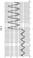
- FIG. 2 illustrating that the voltage applied in the bridge branch voltage signal V measurement as a function of time t. It can be seen that a change in the monitored pipe section at the time t 0 , which promotes leakage or has a drastic effect on the signal course, in particular increases the signal-to-noise ratio, which can be used for manual or automated alarm triggering.
- function modules in the measuring circuit 16 according to FIG. 1 integrated or coupled to this.
- FIG. 3 a special case of the monitoring device is illustrated in a GRP pipe, namely in the region of the coupling 30 between two pipe segments 32, 34.
- a first pipe segment 32 here the left, has a section with a tapered outside diameter at the end and fits snugly into one second tube segment 34, here the right, inserted, which end has a section with a correspondingly widening inner diameter.
- Two circumferential O-ring seals 36 seal the annular / hollow cylindrical gap 38 between the two pipe segments 32, 34.
- a circumferential bracket 40 serves as a mechanical lock and lock for the clutch 30.
- a bayonet lock or the like may be provided.
- a leakage sensor 42 is integrated into the coupling region.
- the leakage sensor 42 here comprises substantially two (generally at least one) fixed to the inner tube segment 32 and projecting into the gap 38 into electrically conductive rings 44, the electrodes of an associated measuring circuit, which similarly as in the embodiment of FIG. 1 may consist of a simultaneously supplied with AC voltage and DC bridge circuit.
- FIG. 4 picks up some details FIG. 3 It is evident that the detailed shape and the electrical contacting of the electrodes 46. It can be seen that the rings 44 of metal braid forming the electrodes 46 projecting into the gap 38 between the two tube segments 32, 34 extend radially into corresponding notches in the tube wall 48 of the inner tube segment 32 arranged metal sleeves 50 are contacted. At the opposite end are the metal sleeves 50 each connected by an electrically / mechanically stable connection, here by spot welding with a embedded in the pipe wall 48 contact bracket 52, to which an electrical connection line 54 is clamped to a connecting element 56.
Abstract
Ein Leckageüberwachungssystem (2) für raumumschließende Objekte, wie etwa Rohre (4), Schläuche oder Behälter mit einer Umfassungswand (6) weist zumindest ein als Leckagesensor (8) wirksames, an der Umfassungswand (6) montiertes oder in diese integriertes elektrisch leitfähiges Element auf. Um auch bei großflächigen Wandbereichen eine einfache und zuverlässige Überwachung auf bevorstehende oder bereits stattfindende Leckagen zu ermöglichen, und dies möglichst universell für verschiedenartige Medien, ist erfindungsgemäß das elektrisch leitfähige Element Bestandteil einer Messbrücke (12), die eine Auswertungsvorrichtung (20) für die Brückenspannung (V Mess ) aufweist, und die über eine Spannungsquelle (18) mit einer Betriebsspannung (U G ) versorgt wird, die sowohl Wechselspannungsanteile als auch Gleichspannungsanteile enthält.A leakage monitoring system (2) for enclosing objects, such as pipes (4), hoses or containers with a surrounding wall (6), has at least one electrically conductive element which is effective as a leakage sensor (8) and which is mounted on the surrounding wall (6) or integrated therein , In order to enable simple and reliable monitoring of impending or already occurring leaks even in large wall areas, and this as universally as possible for various media, according to the invention, the electrically conductive element is part of a measuring bridge (12) comprising an evaluation device (20) for the bridge voltage (20). V measuring), and which is supplied via a voltage source (18) with an operating voltage (UG), which contains both AC components and DC components.
Description
Die Erfindung betrifft ein Leckageüberwachungssystem für raumumschließende Objekte, insbesondere aus Kunststoff, wie etwa Rohre, Schläuche oder Behälter, mit einer ein darin geführtes Medium von der äußeren Umgebung trennenden Umfassungswand, wobei das System zumindest ein als Leckagesensor wirksames, an der Umfassungswand montiertes oder in diese integriertes elektrisch leitfähiges Element aufweist. In einer speziellen Ausprägung erfolgt eine gezielte Überwachung von Kupplungs- oder Übergangsbereichen zwischen derartigen medienführenden Umhüllungen, insbesondere Rohren oder Schläuchen, die in beliebiger Weise und Reihenfolge miteinander kombinierbar sind. Die Erfindung betrifft ferner ein entsprechendes Verfahren zur vorbeugenden und/oder unmittelbaren Leckageüberwachung.The invention relates to a leakage monitoring system for space-enclosing objects, in particular made of plastic, such as pipes, hoses or containers, with a guided therein medium from the outer environment separating the surrounding wall, the system at least one effective as a leakage sensor, mounted on the enclosure wall or in this having integrated electrically conductive element. In a specific embodiment, a targeted monitoring of coupling or transition areas between such media-carrying sheaths, in particular pipes or hoses, which can be combined with one another in any desired manner and sequence. The invention further relates to a corresponding method for preventive and / or immediate leakage monitoring.
In vielen Rohrleitungen, Schläuchen oder Behältern von industriellen Anlagen, insbesondere in kerntechnischen Anlagen, werden Flüssigkeiten oder Gase (allgemein: Fluide) geführt, die für die Umgebung schädlich oder gefährlich sind. Dies macht eine Überwachung derartiger fluidführender oder medienumschließender Objekte auf Leckage notwendig.In many pipelines, hoses or containers of industrial installations, in particular in nuclear installations, liquids or gases (in general: fluids) are conducted which are harmful or dangerous to the environment. This necessitates monitoring of such fluid carrying or media enclosing objects for leakage.
Zu diesem Zweck wurden verschiedenartige Sensortypen und Überwachungsmethoden entwickelt. Beispielsweise ist es bekannt, die Integrität einer Rohrwand mit Hilfe von darin eingebetteten elektrischen Leitern zu überwachen. Die EP 2 287 587 A2 offenbart in diesem Zusammenhang ein System, bei dem basierend auf der Wirkung eines elektrischen Kurzschlusses zwischen zwei in ein Rohr eingebrachten Leitern eine Überwachungsaufgabe gelöst wird.For this purpose, various sensor types and monitoring methods have been developed. For example, it is known to monitor the integrity of a pipe wall by means of electrical conductors embedded therein.
Ein derartiges System ist jedoch weder spezifisch dafür ausgelegt, noch sensitiv genug, um auch kleinste Leckagen von Fluiden, etwa an Nahtstellen einer Rohr- oder Behälterwand oder durch Mikroporen hindurch, zuverlässig festzustellen.However, such a system is neither specifically designed nor sensitive enough to reliably detect even the smallest leaks of fluids, such as at seams of a pipe or vessel wall or through micropores.
Der vorliegenden Erfindung liegt die Aufgabe zugrunde, ein Leckageüberwachungssystem der eingangs genannten Art anzugeben, welches auch bei großflächigen Wandbereichen eine einfache und zuverlässige Überwachung auf kleinste Leckagen ermöglicht, und dies möglichst universell für verschiedenartige Fluide oder Medien. Insbesondere wird eine vorbeugende Überwachung angestrebt, die bereits vor einer tatsächlich einsetzenden, also bei einer bevorstehenden Leckage anspricht. Weiterhin soll ein entsprechendes Verfahren angegeben werden.The present invention has for its object to provide a leakage monitoring system of the type mentioned above, which allows for large wall areas easy and reliable monitoring for the smallest leaks, and this as universally as possible for various fluids or media. In particular, a preventive monitoring is sought, which responds already before an actual onset, so in an impending leakage. Furthermore, a corresponding method should be specified.
In Bezug auf die Vorrichtung wird die Aufgabe erfindungsgemäß gelöst durch die Merkmale des Anspruchs 1 und in Bezug auf das Verfahren durch die Merkmale des Anspruchs 9.With regard to the device, the object is achieved according to the invention by the features of claim 1 and with respect to the method by the features of claim 9.
Demzufolge ist das an der Umfassungswand montierte oder in diese integrierte elektrisch leitfähige Element Bestandteil einer Messbrücke, die eine Auswertungsvorrichtung für die Brückenspannung aufweist, und die über eine Spannungsquelle mit einer Betriebsspannung versorgt wird, die sowohl Wechselspannungsanteile als auch Gleichspannungsanteile enthält. Das elektrisch leitfähige oder im Allgemeinen elektrisch wirksame Element kann dabei jegliche für die Überwachungsaufgabe zweckmäßige räumliche Form und Struktur aufweisen, insbesondere eine Sensorschicht bilden, und wird im Folgenden vereinfachend auch kurz als Leiter bezeichnet.Consequently, the electrically conductive element mounted on the surrounding wall or constituting it is part of a measuring bridge which has a bridge voltage evaluation device and which is supplied via a voltage source with an operating voltage which contains both AC components and DC components. The electrically conductive or generally electrically effective element may have any spatial form and structure suitable for the monitoring task, in particular forming a sensor layer, and will for brevity also be referred to as conductor for the sake of simplicity.
Die Erfindung geht davon aus, dass im Wand- oder Hüllmaterial zumindest ein elektrisch wirksamer Sensor (z. B. ein leitfähiges Maschennetz oder Gitter oder eine Anordnung von Drähten, aber auch Elemente aus leitfähigem oder halbleitendem Material in anderer Gestalt) zwischen der vom Medium abgewandten Außenseite und der mediumführenden Innenseite eingebracht ist. Die Anordnung des Sensormaterials wird als gegeben angenommen. Als Sensormaterialien können alle Materialien verwendet werden, die eine ausreichend große Änderung einer ihrer elektrischen Kenngrößen - insbesondere elektrischer Widerstand, Kapazität und/oder Induktivität - für den Fall einer Leckage liefern.The invention assumes that at least one electrically effective sensor (for example a conductive mesh or grid or an arrangement of wires, but also elements of conductive or semiconductive material in a different shape) is disposed between the medium and the wall material Outside and the medium-carrying inside is introduced. The arrangement of the sensor material is taken for granted. As sensor materials, all materials can be used which have a sufficiently large change in a their electrical characteristics - in particular electrical resistance, capacitance and / or inductance - provide in the event of leakage.
Darüber hinaus wird nicht durch eine tatsächliche Leckage detektiert, sondern es ist bevorzugt eine vorbeugende oder vorhersagende Überwachung möglich in dem Sinne, dass bereits eine einer Leckage vorausgehende Material- oder Gefügeänderung des Wandmaterials, etwa durch Beschädigung, Abnutzung, Erosion und dergleichen, zu einer Änderung elektrischer Kenngrößen führt, die messtechnisch detektiert und ggf. zur Alarmauslösung verwendet wird - noch bevor es tatsächlich zur Leckage kommt. Wenn im Rahmen dieser Beschreibung vereinfachend von einer Überwachung auf Leckage die Rede ist, ist stets der Fall einer derartigen vorbeugenden Überwachung auf eine drohende oder unmittelbar bevorstehende Leckage mit enthalten. Entsprechend sind auch Begriffe wie "Leckagesensor" und dergleichen zu verstehen.In addition, it is not detected by an actual leakage, but it is preferably a preventive or predictive monitoring possible in the sense that already a leakage preceding material or structural change of the wall material, such as damage, wear, erosion and the like, to a change electrical parameters, which is detected by measurement and possibly used for alarm triggering - even before it actually comes to leakage. If, in the context of this description, a simplification is to be understood as monitoring for leakage, the case of such preventive monitoring for imminent or imminent leakage is always included. Accordingly, terms such as "leakage sensor" and the like are to be understood.
Der Erfindung liegt die Idee zugrunde, den auf diese Weise verwirklichten Sensor messtechnisch in eine Wechselspannungs-Messbrücke einzubeziehen. Es wird damit durch die Messung und Auswertung der Brückenspannung, insbesondere hinsichtlich Frequenz, Betrag und Phasenlage, eine Bewertung des komplexen elektrischen Widerstandes (Impedanz) vorgenommen. Dies berücksichtigt sowohl ohmsche als auch kapazitive und/oder induktive Änderungen der Anordnung, die durch eine mit der Leckage einhergehende oder ihr vorausgehende Materialänderung hervorgerufen werden.The invention is based on the idea of metrologically integrating the sensor realized in this way into an AC measuring bridge. It is thus made by the measurement and evaluation of the bridge voltage, in particular with regard to frequency, magnitude and phase, an assessment of the complex electrical resistance (impedance). This takes into account both ohmic and capacitive and / or inductive changes of the arrangement, which are caused by a material change associated with or preceding the leakage.
Der eigentliche Sensor ist somit ein in das Überwachungsobjekt, etwa in eine Rohr- / Schlauch- / Behälterwand, integriertes Element der Messbrücke. Die sonstigen elektrischen / elektronischen Komponenten, die die Anordnung zu einer vollständigen Messbrücke ergänzen, werden in einer separaten Messschaltung realisiert. Die messtechnische Anordnung kann am Prüfling, in seiner unmittelbaren Nähe oder entfernt angebracht werden.The actual sensor is thus an element of the measuring bridge integrated in the monitored object, for example in a tube / hose / container wall. The other electrical / electronic components, which complete the arrangement to form a complete measuring bridge, are realized in a separate measuring circuit. The metrological arrangement can be placed on the test piece, in its immediate vicinity or remotely.
Wesentlich ist, dass die Messbrücke sowohl mit Gleich- als auch Wechselspannung einer bestimmten, bekannten Frequenz gespeist wird. Die Auslegung der Schaltung ermöglicht es, dass kleinste Änderungen der elektrischen Parameter (verursacht durch die zu einer Leckage führenden Material- oder Formänderungen) sowohl zu einer großen Amplitudenänderung als auch zu einer Veränderung der Signalform infolge der Überlagerung von Gleich- und Wechselspannungsanteilen führen. Dies erhöht die Auswerte- und Bewertungssicherheit des erzeugten Signales gegenüber Störungen und dem Signal im Gut-Zustand.It is essential that the measuring bridge is fed with both DC and AC voltage of a certain known frequency. The interpretation of Circuit allows small changes in the electrical parameters (caused by leaking material or shape changes) to result in both a large amplitude change and a change in waveform due to the superposition of DC and AC components. This increases the evaluation and evaluation reliability of the generated signal against interference and the signal in the good state.
Die Auswerteeinheit umfasst bevorzugt eine elektronische Verarbeitungseinheit für das Messsignal. Sie kann in einem einfachen Fall lediglich in einer Anzeigevorrichtung für das Messsignal bestehen aber natürlich auch noch weitere und/oder alternative Komponenten besitzen. Beispielsweise kann eine elektronische Speichereinheit für das Messsignal vorhanden sein, etwa in Gestalt eines Ringspeichers und/oder Permanentspeichers. Weiterhin ist ein Diagnosemodul vorteilhaft, das beispielsweise anhand von Schwellwerten und/oder von einschlägigen Auswertungsalgorithmen plötzliche und/oder langfristige Änderungen des Messsignals, die auf eine drohende / bevorstehende / gerade einsetzende oder bereits stattfindende Leckage hindeuten, automatisch erkennt und/oder in verschiedene Merkmalsgruppen klassifiziert und insbesondere zur Alarmauslösung verwendet.The evaluation unit preferably comprises an electronic processing unit for the measurement signal. In a simple case, it can merely consist of a display device for the measurement signal, but of course also have further and / or alternative components. For example, an electronic memory unit for the measurement signal may be present, for example in the form of a ring memory and / or permanent memory. Furthermore, a diagnostic module is advantageous which, for example based on threshold values and / or relevant evaluation algorithms, automatically detects sudden and / or long-term changes in the measurement signal which indicate an impending / imminent or already occurring leakage and / or classified into different feature groups and especially used for alarm triggering.
Die Frequenz der Wechselspannung ist vorzugsweise umschaltbar oder überdeckt einen bestimmten Frequenzbereich. Die Umschaltung der Frequenz kommt insbesondere dann zum Einsatz, wenn bei einer Plausibilitätsprüfung der Brückenverstimmung bestimmte Kriterien zu keiner schlüssigen Bewertung des Signales führen.The frequency of the alternating voltage is preferably switchable or covers a certain frequency range. The switching of the frequency is used in particular when certain criteria lead to a conclusive evaluation of the signal in a plausibility check of the bridge detuning.
Die Messschaltung ist vorzugsweise bandbegrenzt, d. h. sie arbeitet nur in einem kleinen Frequenzbereich um die Grundfrequenz. Diese Auslegung wird auch dann beibehalten, wenn die Frequenz wie oben beschrieben umgeschaltet wird.The measuring circuit is preferably band-limited, d. H. it works only in a small frequency range around the fundamental frequency. This design is maintained even if the frequency is switched as described above.
Im Einklang mit dem Messprinzip ist das Wand- bzw. Hüllmaterial des zu überwachenden Objektes, etwa des Rohres / Schlauches / Behälters, vorzugsweise nicht elektrisch leitfähig, insbesondere nicht-metallisch. Stattdessen eignet sich die Methode besonders zur vorbeugenden und unmittelbaren Leckageüberwachung von mediumgrenzenden Kunststoffbauteilen (Kunststoffplatten, -rohre, -schläuche, - behälter). Es ist aber auch möglich, Objekte mit einer Metallaußenwand oder Objekte mit einer vorhandenen Metall-Nichtmetall-Compositestruktur auf die beschriebene Weise zu überwachen, wobei die metallischen Bestandteile oder Teile davon die sensorisch wirksamen Elemente, die in die Messbrücke eingekoppelt werden, bilden.In accordance with the measuring principle, the wall or shell material of the object to be monitored, for example of the tube / hose / container, is preferably not electrically conductive, in particular non-metallic. Instead, the method is particularly suitable for preventive and immediate leakage monitoring of Medium-border plastic components (plastic sheets, pipes, hoses, tanks). However, it is also possible to monitor objects with a metal outer wall or objects with an existing metal-nonmetal composite structure in the manner described, wherein the metallic constituents or parts thereof form the sensory elements which are coupled into the measuring bridge.
Bei der Überwachung von mehreren Objekten mit Hilfe von mehreren Sensoren und zugehörigen Messbrücken wird vorteilhafterweise jedem überwachten Objekt (das kann z. B. ein Rohrstück sein oder eine Teilfläche einer größeren Wandfläche) eine eindeutige individuelle Kennung zugeordnet, anhand derer es identifiziert werden kann. Die Messergebnisse und deren Bewertung können so dieser Kennung zugeordnet werden. Dadurch ist es möglich, die in einem späteren Stadium zur Leckage führende Veränderungs- oder Beschädigungsstelle im Wandmaterial, vereinfacht auch als Leckagestelle bezeichnet, zu lokalisieren.When monitoring a plurality of objects with the aid of a plurality of sensors and associated measuring bridges, it is advantageous for each monitored object (for example a pipe section or a subarea of a larger wall surface) to be assigned a unique individual identifier by means of which it can be identified. The measurement results and their evaluation can be assigned to this identifier. This makes it possible to localize the change or damage point leading to leakage in the wall material at a later stage, also referred to as leakage point.
Allgemein gesprochen kann die beschriebene Überwachungsvorrichtung in ein System einbezogen werden, das in der Lage ist, eine Ortsinformation bezüglich der Beschädigung zu liefern. Dies ist insbesondere dann möglich, wenn das Sensorelement oder die Elektrode des Messkreises eineindeutig einer signalverarbeitenden Einheit zugeordnet sind, die ihrerseits das gemessene Signal mit einer systemweit eineindeutigen Identifikation verknüpft.Generally speaking, the monitoring device described can be incorporated into a system capable of providing location information regarding the damage. This is possible in particular when the sensor element or the electrode of the measuring circuit is uniquely associated with a signal processing unit, which in turn links the measured signal to a system-wide one-to-one identification.
Es ist auch möglich, eine Anordnung der Überwachungsorte in einzelne Sektionen einzuteilen, die mit einer zentralen Verarbeitungseinrichtung verbunden sind. Die Übermittlung des originalen und des bewerteten Messsignales kann über ein zuverlässiges Bussystem zu der zentralen Verarbeitungseinrichtung (z. B. Hostcomputer) erfolgen.It is also possible to divide an arrangement of the monitoring sites into individual sections, which are connected to a central processing device. The transmission of the original and the weighted measurement signal can be made via a reliable bus system to the central processing device (eg host computer).
Mit der erfindungsgemäßen Messanordnung kann auch eine Schwingungs- oder Erschütterungsüberwachung für raumumschließende Objekte wie etwa Rohre, Schläuche oder Behälter und/oder dazwischen liegende Kupplungsbereiche erfolgen. Dies kann in der beschriebenen Weise durch Impedanzmessung im Bereich der Umfassungswand des überwachten Objekts und durch Auswertung der zeitlichen Änderungen erfolgen. Mit anderen Worten wird bei der Auswertung von zeitlichen Impedanzänderungen auf solche Änderungen verursachende Bewegungen oder Beschleunigungen von Rohr- oder sonstigen Segmenten geschlossen. Alternativ oder zusätzlich können dezidierte Beschleunigungssensoren, insbesondere in Chipform, in/an dem Objekt angeordnet sein, die entsprechende Beschleunigungsmesswerte unmittelbar bereitstellen.With the measuring arrangement according to the invention, a vibration or vibration monitoring for space-enclosing objects such as pipes, hoses or containers and / or intermediate coupling regions can be carried out. This can be done in the manner described by impedance measurement in the field the enclosure wall of the monitored object and by evaluating the changes over time. In other words, in the evaluation of temporal impedance changes to such changes causing movements or accelerations of pipe or other segments is concluded. Alternatively or additionally, dedicated acceleration sensors, in particular in chip form, may be arranged in / on the object, which directly provide corresponding acceleration measurement values.
Eine derartige Schwingungs- oder Erschütterungsüberwachung kann insbesondere eine oder mehrere der folgenden Zielsetzungen verfolgen, hier am Beispiel einer Pipeline veranschaulicht:
- a) Einbruchsmeldung (engl. intrusion detection): Überwachung einer Pipeline auf mechanische Manipulationen, z.B. gezieltes Anbohren oder durch Vandalismus. Aber auch Erkennung von Baumaßnahmen in der Umgebung, die die Sicherheit bzw. Integrität der Pipeline gefährden.
- b) Seismische Überwachung: Seismische Aktivitäten können in der gesamten Pipeline erfasst werden. Über eine Messpunktortung kann das Epizentrum lokalisiert werden. Die Messdaten werden für das Alterungsmanagement (engl. aging management) gespeichert und ausgewertet.
- c) Betriebsvibrationen: Vibrationen, die aus dem laufenden Betrieb resultieren, werden erfasst und aufgezeichnet. Kurzzeitevents wie z.B. Kavitation werden erfasst. Die erfassten Messdaten werden ebenfalls zentral gespeichert und für das Alterungsmanagement ausgewertet.
- a) intrusion detection: monitoring of a pipeline for mechanical manipulation, eg targeted drilling or vandalism. But also detection of building measures in the environment that endanger the security or integrity of the pipeline.
- b) Seismic monitoring: seismic activity can be recorded throughout the pipeline. The epicenter can be located via a measuring point location. The measured data is stored and evaluated for aging management (English: aging management).
- c) Operating vibrations: Vibration resulting from operation is recorded and recorded. Short-term events such as cavitation are recorded. The recorded measurement data are also stored centrally and evaluated for aging management.
Um die Messanordnung auf ordnungsgemäßen Zustand prüfen zu können, sind vorteilhafterweise Referenzschaltungen vorgesehen, die ein bekanntes Signal erzeugen können und dieses im Test- bzw. Prüfbetrieb und ggf. zum Zwecke einer Kalibrierung anstelle des Sensorsignales in die Messbrücke einspeisen.In order to be able to check the measuring arrangement for proper condition, reference circuits are advantageously provided which can generate a known signal and feed it into the measuring bridge in the test or test mode and, if necessary, for the purpose of calibration instead of the sensor signal.
Die Anordnung kann auch mit Feuchte- und/oder Temperatursensoren und/oder anderen Sensoren (etwa Beschleunigungssensoren) zur Erfassung der Umgebungsbedingungen oder bestimmter Materialeigenschaften versehen werden. Damit lassen sich dann weitere statistische oder messtechnische Bewertungen durchführen.The arrangement can also be provided with humidity and / or temperature sensors and / or other sensors (such as acceleration sensors) for detecting the environmental conditions or certain material properties. This can then be used to perform further statistical or metrological evaluations.
Von besonderem Interesse ist in diesem Zusammenhang die Temperaturmessung. Ähnlich zur Schwingungsüberwachung wird bevorzugt mindestens ein Temperatursensor auf jedem interessierenden Überwachungsmodul bzw. Rohrsegment realisiert / installiert. Der Temperatursensor kann auf/an der Innenseite oder der Außenseite der fluidführenden Umschließung angeordnet oder auch in die Wand integriert sein.Of particular interest in this context is temperature measurement. Similar to the vibration monitoring, at least one temperature sensor is preferably realized / installed on each monitoring module or pipe segment of interest. The temperature sensor can be arranged on / on the inside or the outside of the fluid-carrying enclosure or can also be integrated in the wall.
Temperaturmesswerte werden bevorzugt zyklisch abgefragt und zentral in einer Datenbank gespeichert. Es gibt zwei vorteilhafte Grundtypen der Auswertung:
- A posteriori:
- Bei Pre-Leakage Alarm werden die gespeicherten Temperarturdaten untersucht und ermittelt, ob temperaturbedingte Materialermüdungserscheinungen aufgetreten sind.
- A priori:
- Unter Berücksichtigung der Temperaturdaten kann eine verlässliche Prognose für diskrete Rohrsegmente bezüglich der maximalen Lebensdauer / Laufzeiterwartung gestellt werden. Daraus wird eine Austauschempfehlung an den Betreiber abgeleitet.
- A posteriori:
- Pre-Leakage Alarm examines the stored temperature data and determines if temperature-related material fatigue has occurred.
- A priori:
- Taking into account the temperature data, a reliable forecast for discrete pipe segments can be made regarding the maximum service life / life expectancy. From this an exchange recommendation to the operator is derived.
Allgemein werden bevorzugt alle Messdaten aus Pre-Leakage Monitoring, Schwingungsüberwachung und Temperaturüberwachung in einer Datenbank gespeichert. Alle Daten können miteinander verknüpft werden. Durch eine geeignete Gewichtung der einzelnen Einflussfaktoren kann ein Trend für jedes interessierenden Überwachungsmodul bzw. Rohrsegment berechnet werden (Alterungsmanagement).In general, all measured data from pre-leakage monitoring, vibration monitoring and temperature monitoring are preferably stored in a database. All data can be linked together. By appropriate weighting of the individual influencing factors, a trend can be calculated for each monitoring module or pipe segment of interest (aging management).
Die messtechnische Anordnung kann über ein Datennetz mit anderen Stellen vernetzt werden und Informationen austauschen, beispielsweise um die Sensorsignale bezüglich klimatischer Einflüsse zu stabilisieren. Ebenso ist es möglich, die messtechnische Anordnung von extern zu überprüfen, ihr Parameter zuzustellen oder Informationen von ihr abzurufen.The metrological arrangement can be networked via a data network with other bodies and exchange information, for example, to stabilize the sensor signals with respect to climatic influences. It is also possible to externally check the metrological arrangement, to supply its parameters or to retrieve information from it.
Die Anordnung und Methode führt bevorzugt zu einer Erzeugung von Warnungen oder Alarmen oder von Informationen, die zur Alarmauslösung verwendet werden können. Es ist möglich, das interessierende Objekt kontinuierlich oder zyklisch zu überwachen.The arrangement and method preferably results in the generation of warnings or alarms or information that can be used to trigger the alarm. It is possible to continuously or cyclically monitor the object of interest.
Bislang lag der Schwerpunkt der Beschreibung auf der Überwachung flächiger Bereiche, insbesondere der Leckageüberwachung von Rohrkörpern. In analoger Weise kann aber auch eine gezielte Überwachung von Kupplungs- und Übergangsbereichen bei Rohr- / Schlauch- / Behältnis- und ähnlichen Objektverbindungen auf eine zur Leckage führende oder sie begünstigende Veränderung oder Beschädigung im Kupplungsspalt zwischen den beiden miteinander verbundenen Komponenten erfolgen. Auch in diesem Fall wird eine überwiegend elektrisch nicht-leitende Charakteristik des Rohrwand-Materials, jedenfalls in der Kupplungsregion, bevorzugt.So far, the emphasis of the description has been on the monitoring of areal areas, in particular the leakage monitoring of tubular bodies. In an analogous manner, however, a targeted monitoring of coupling and transition areas in pipe / hose / container and similar object connections can be made on a leaking or favoring change or damage in the coupling gap between the two interconnected components. Also in this case, a predominantly electrically non-conductive characteristic of the tube wall material, at least in the coupling region, is preferred.
In diesem Fall umfasst die bevorzugte Anordnung der den Leckagesensor bildenden elektrischen Leiter im Wesentlichen einen oder mehrere die Verbindungsstelle vollständig umschließende leitfähige Ringe, die die Elektroden eines elektrischen Messkreises bilden. Bei den Ringen kann es sich insbesondere um elek-trisch leitfähige O-Ringe oder andere ring- oder hohlzylinderförmige Objekte in speziellen Anwendungen handeln, die auch Dichtfunktionen übernehmen können. Der Messkreis ist so gestaltet, dass Leckage-begünstigende Veränderungen in diesem Bereich zu einer wesentlichen Verstimmung des elektrischen Arbeitspunktes führen. Damit wird eine derartige Veränderung - insbesondere nach einer mediumbezogenen Bewertung der Änderung z. B. der Leitfähigkeit - eindeutig detektierbar. Mit anderen Worten kann auch hier eine signifikante Änderung elektrischer Parameter, im Allgemeinen der (komplexen) Impedanz, der umschließenden Anordnung von elektrisch leitfähigen Ringen festgestellt werden, die insbesondere mit der oben beschriebenen Brückenschaltung messtechnisch detektierbar ist.In this case, the preferred arrangement of the electrical sensor forming the leakage sensor essentially comprises one or more conductive rings completely enclosing the connection point, which form the electrodes of an electrical measuring circuit. The rings may in particular be electrically conductive O-rings or other ring-shaped or hollow-cylindrical objects in special applications which may also assume sealing functions. The measuring circuit is designed so that leakage-promoting changes in this area lead to a significant detuning of the electrical operating point. Thus, such a change - especially after a medium-based assessment of the change z. As the conductivity - clearly detectable. In other words, here too, a significant change in electrical parameters, in general the (complex) impedance, of the enclosing arrangement be detected by electrically conductive rings, which is detectable in particular by the bridge circuit described above metrologically.
Für den allgemeinen Anwendungsfall "Rohrüberwachung auf Leckage" ist es selbstverständlich möglich, die Überwachung des Rohrkörpers (Flächenüberwachung) und der Kupplung zwischen Rohrsegmenten zu koppeln bzw. miteinander zu kombinieren. Dies gilt in verallgemeinerter Weise auch für nicht-rohrförmige Objekte.For the general application "pipe monitoring for leakage", it is of course possible to couple the monitoring of the pipe body (area monitoring) and the coupling between pipe segments or to combine with each other. This applies in a generalized way also for non-tubular objects.
Die mit der Erfindung erzielten Vorteile bestehen insbesondere darin, dass durch die geschickte Kombination einer messtechnischen Methode und geeigneter signalverarbeitender Verfahren eine zuverlässige Entdeckung und Lokalisierung auch von geringfügigen Leckagen "in statu nascendi" oder sogar schon vorher (im Sinne einer vorbeugenden Überwachung) in medienführenden Rohrleitungen, Schläuchen, Strömungswegen, Tanks, Behältern und dergleichen ermöglicht ist. Es ist auch eine gezielte Überwachung von Rohrkupplungen und ähnlichen Verbindungsstellen mediumführender Umschließungen möglich. Wesentliche Aspekte im Hinblick auf die erzielte Sensitivität liegen in der Wahl der Messbrückenspeisung, in der Auswertung des resultierenden Messbrückensignales und in der Art und Weise, wie eine kleine Änderung des Sensorsignales einen großen Signalhub erzeugt. Die integrierte und permanent verfügbare Methode ist somit robust und führt zu einem ausreichenden Signalabstand zwischen Normalzustand und Leckage-begünstigendem Störungszustand. Die Sensoranordnung lässt sich überdies einfach unter Verwendung marktverfügbarer Materialien fertigen und ist für eine lange Einsatzdauer geeignet.The advantages achieved by the invention are, in particular, that by the clever combination of a metrological method and suitable signal processing methods reliable detection and localization of even minor leaks "in statu nascendi" or even before (in the sense of preventive monitoring) in media-carrying pipelines , Hoses, flow paths, tanks, containers and the like is possible. It is also a targeted monitoring of pipe couplings and similar joints medium-leading enclosures possible. Essential aspects with regard to the achieved sensitivity lie in the choice of the measuring bridge feed, in the evaluation of the resulting measuring bridge signal and in the way in which a small change in the sensor signal generates a large signal swing. The integrated and permanently available method is thus robust and leads to a sufficient signal distance between the normal state and the leakage-promoting disturbance state. Moreover, the sensor arrangement can be easily manufactured using commercially available materials and is suitable for a long service life.
Ein Ausführungsbeispiel der Erfindung wird nachfolgend anhand von Zeichnungen näher erläutert. Dabei zeigen:
- FIG. 1
- ein stark vereinfachtes und schematisiertes Prinzipschaltbild eines Leckageüberwachungssystems für raumumschließende Objekte wie etwa Rohre, Schläuche oder Behälter,
- FIG. 2
- ein Beispiel des zeitlichen Verlaufs eines mit einem Leckageüberwachungssystem gemäß
FIG. 1 aufgenommenen Messsignals, - FIG. 3
- einen Längsschnitt durch eine Rohrkupplung mit einer Elektrodenanordnung zur Leckagedetektion in diesem Bereich (nur eine Rohrhälfte ist dargestellt),
- FIG. 4
- einen vergrößerten Ausschnitt aus
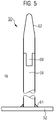
FIG. 3 , und - FIG. 5
- ein Detail aus
FIG. 4 .
- FIG. 1
- a highly simplified and schematized schematic diagram of a leakage monitoring system for space enclosing objects such as pipes, hoses or containers,
- FIG. 2
- an example of the time course of a with a leakage monitoring system according to
FIG. 1 recorded measuring signal, - FIG. 3
- a longitudinal section through a pipe coupling with an electrode assembly for leakage detection in this area (only one half of the tube is shown),
- FIG. 4
- an enlarged section
FIG. 3 , and - FIG. 5
- a detail from
FIG. 4 ,
Gleiche Teile sind in allen Figuren mit denselben Bezugszeichen versehen.Identical parts are provided with the same reference numerals in all figures.
Das in
Ein weiteres Beispiel ist die Überwachung flächiger Kunststoffbauteile, wie sie im Behälterbau Verwendung finden.Another example is the monitoring of flat plastic components, as used in container construction.
Zu diesem Zweck ist in das aus einem Kunststoff bestehende, elektrisch nicht-leitende Hüllmaterial der Umfassungswand 6 ein Sensor 8 in Gestalt eines elektrisch leitenden Materials, hier beispielsweise in Gestalt eines Drahtnetzes oder Gewebes integriert. Konkret handelt es sich im Ausführungsbeispiel um ein GFK-Rohr, in dessen Wand zumindest ein Metall- oder Kohlenstofffaser- oder CFK-Gewebe als elektrisch leitendender Sensor eingebracht wurden. Dabei steht GFK für glasfaserverstärkten Kunststoff, und CFK für kohlefaserverstärkten Kunststoff. Das leitende Gewebe deckt hinsichtlich seiner Ausdehnung vorzugsweise die gesamte zu überwachende Wandfläche ab.For this purpose, a sensor 8 in the form of an electrically conductive material, here for example in the form of a wire mesh or fabric, is integrated in the plastic nonconductive enveloping material of the surrounding
Das elektrische leitende Gewebe ist an zwei möglichst weit voneinander entfernt liegenden Stellen, etwa an dem einen und dem anderen Rohrende, mit jeweils einer elektrischen Anschlussleitung 10 verbunden, die aus der Umfassungswand 6 des Rohres 4 herausgeführt ist. Der dadurch verwirklichte zweipolige Sensor 8 lässt sich in dem dargestellten Ersatzschaltbild in erster Näherung als eine Parallelschaltung eines ohmschen Widerstandes RSensor und eines Kondensators (Kapazität) CSensor charakterisieren. Dieses Ersatzschaltbild ist nur exemplarisch zu verstehen; es können in der Praxis auch kompliziertere Fälle mit alternativ oder zusätzlich vorhandenen Induktivitäten in Parallel- und/oder Serienschaltung auftreten.The electrically conductive tissue is connected to two points as far as possible from each other remote locations, such as at one and the other end of the tube, each having an
Im Falle einer drohenden Leckage von in dem Rohr 4 geführten Fluid oder Medium durch die Umfassungswand 6 nach außen, hervorgerufen beispielsweise durch mechanische Abnutzung oder Beschädigung, ändert sich zumindest eine der elektrischen Kenngrößen Widerstand, Kapazität und/oder Induktivität des Sensors 8. Ursachen hierfür können beispielsweise eine lokale Änderung der Dielektrizität und/oder mechanische Verformungen des leitenden Gewebes an Bruchstellen sein. Dies ist im Ersatzschaltbild - wiederum rein exemplarisch - durch den ohmschen Zusatzwiderstand RLeck, hier in Parallelschaltung zu dem Widerstand Rsensor, angedeutet. Im Allgemeinen können sich auch die Kapazität und die Induktivität des Sensors 8 infolge der Veränderung in der Rohrwand und/oder des Leckagestroms ändern. Ganz allgemein kann man davon sprechen, dass sich der komplexe Wechselstromwiderstand (Impedanz) des Sensors 8 bei einer Leckagebegünstigenden Gefügeänderung ändert.In the case of a threatening leakage of out in the
Zur Detektion derartiger Impedanzänderungen, die bei geringfügigen Änderungen vergleichsweise klein ausfallen können, ist der in das Rohr 4 integrierte Sensor 8 über seine Anschlussleitungen 10 in eine Wechselspannungsmessbrücke, kurz Messbrücke 12 eingekoppelt, die nach dem Grundprinzip einer Wheatstone-Messbrücke aufgebaut ist und konkret beispielsweise als Wien-Brücke oder Maxwell-Wien-Brücke verwirklicht ist. Die zur Vervollständigung der Brückenschaltung und zur Auswertung notwendigen elektronischen Komponenten, hier rein schematisch und beispielhaft angedeutet durch einen Messwiderstand RMess1, einen Messwiderstand RMess2 und einen Messkondensator CMess sind in eine außerhalb des Rohres 4 angeordnete Messschaltung 16 ausgelagert. Im Allgemeinen kann die Messschaltung 16 anstelle der idealisierten elektrischen Bauelemente RMess1, RMess2 und CMess drei komplexe Messwiderstände aufweisen, die zusammen mit dem komplexen Sensorwiderstand des Sensors 8 die Messbrücke 12 bilden, an deren Brückenzweig ein Spannungssignal VMess (Diagonalspannung oder Brückenquerspannung) abgegriffen wird.To detect such impedance changes, which may be comparatively small with slight changes, the integrated into the
Das im analogen Teil der Messschaltung 16 abgegriffene Spannungssignal VMess wird hier im Ausführungsbeispiel über entsprechende Anschlüsse und Leitungen einer digitalen Auswertungsvorrichtung 20 zugeführt, die beispielsweise einen Operationsverstärker 22 oder sonstigen Signalverstärker und einen Mikrocontroller 24 aufweist. Zur Visualisierung der in der Auswertungsvorrichtung 20 aufbereiteten und ggf. im Hinblick auf eine mögliche Leckage bewerteten Messergebnisse ist zweckmäßigerweise eine hier nicht dargestellte Anzeigevorrichtung vorgesehen.The tapped in the analog part of the measuring
Im Gegensatz zur gleichspannungsgespeisten Wheatstone-Brücke wird die Messbrücke 12 über eine Spannungsquelle 18 mit einer Betriebsspannung UG versorgt, die sowohl Wechselspannungsanteile, vorzugsweise mit einer einzigen festen Grundfrequenz ω, als auch Gleichspannungsanteile enthält, nämlich in Form einer Überlagerung oder Superposition, also beispielsweise U(t) = U0 + U1 cos(ωt). Dadurch ändert sich die im Brückenzweig abgegriffene Brückenquerspannung VMess in der Regel drastisch, auch wenn sich die Impedanz des Sensors 8 nur geringfügig infolge einer Leckage bzw. einer zur Leckage führenden Gefügeänderung ändert.In contrast to the DC powered Wheatstone bridge, the measuring bridge 12 is supplied via a
Dies ist in
In
Zur (vorbeugenden) Detektion einer bevorstehenden oder stattfindenden Leckage von Strömungsmedium aus dem Rohrinneren durch den Spalt 38 hindurch in die Umgebung, wie sie insbesondere bei einer Beschädigung der beiden O-Ring-Dichtungen 36 auftreten kann, ist ein Leckagesensor 42 in die Kupplungsregion integriert. Der Leckagesensor 42 umfasst hier im Wesentlichen zwei (im Allgemeinen zumindest einen) am inneren Rohrsegment 32 fixierte und in den Spalt 38 hinein ragende elektrisch leitfähige Ringe 44, die Elektroden einer zugehörigen Messschaltung bilden, welche ähnlich wie im Ausführungsbeispiel gemäß
Eine der Metallhülsen 50 ist in
Das Aufsatzteil 62 kann zum Zwecke einer elektrischen Kontaktierung nach der Herstellung entfernt werden. Dann ist an dem Gewindefortsatz 60 ein elektrischer Anschluss möglich, der Teil der in
Claims (7)
Applications Claiming Priority (2)
| Application Number | Priority Date | Filing Date | Title |
|---|---|---|---|
| DE102013227043.7A DE102013227043A1 (en) | 2013-12-20 | 2013-12-20 | Leakage monitoring system for room enclosing objects and intermediate coupling areas and associated method |
| EP14818918.6A EP3084382B1 (en) | 2013-12-20 | 2014-12-10 | Leak detection system for volume encompassing objects and in between lying areas |
Related Parent Applications (2)
| Application Number | Title | Priority Date | Filing Date |
|---|---|---|---|
| EP14818918.6A Division-Into EP3084382B1 (en) | 2013-12-20 | 2014-12-10 | Leak detection system for volume encompassing objects and in between lying areas |
| EP14818918.6A Division EP3084382B1 (en) | 2013-12-20 | 2014-12-10 | Leak detection system for volume encompassing objects and in between lying areas |
Publications (1)
| Publication Number | Publication Date |
|---|---|
| EP3282237A1 true EP3282237A1 (en) | 2018-02-14 |
Family
ID=52146456
Family Applications (2)
| Application Number | Title | Priority Date | Filing Date |
|---|---|---|---|
| EP17186247.7A Withdrawn EP3282237A1 (en) | 2013-12-20 | 2014-12-10 | Leak detection system for objects enclosing rooms and coupling areas between same and associated method |
| EP14818918.6A Active EP3084382B1 (en) | 2013-12-20 | 2014-12-10 | Leak detection system for volume encompassing objects and in between lying areas |
Family Applications After (1)
| Application Number | Title | Priority Date | Filing Date |
|---|---|---|---|
| EP14818918.6A Active EP3084382B1 (en) | 2013-12-20 | 2014-12-10 | Leak detection system for volume encompassing objects and in between lying areas |
Country Status (9)
| Country | Link |
|---|---|
| US (1) | US20160299030A1 (en) |
| EP (2) | EP3282237A1 (en) |
| JP (1) | JP6550389B2 (en) |
| CN (1) | CN105829854B (en) |
| BR (1) | BR112016012534B1 (en) |
| CA (1) | CA2933675A1 (en) |
| DE (1) | DE102013227043A1 (en) |
| RU (1) | RU2016129275A (en) |
| WO (1) | WO2015091170A1 (en) |
Families Citing this family (7)
| Publication number | Priority date | Publication date | Assignee | Title |
|---|---|---|---|---|
| DE102016212986A1 (en) * | 2016-07-15 | 2018-01-18 | Volkswagen Aktiengesellschaft | Liquid measuring device and measuring head device for moisture detection, in particular in containers for liquid-sensitive electrical and / or electronic components in road vehicles |
| DK3462156T3 (en) * | 2017-09-27 | 2020-02-17 | Smart Leak Solution Sls Ltd | System and method for detecting and locating a leak |
| US10769684B1 (en) | 2017-10-03 | 2020-09-08 | Wells Fargo Bank, N.A. | Property assessment system with buoyancy adjust device |
| KR102227603B1 (en) * | 2020-10-30 | 2021-03-12 | 유종근 | Integrated Leak Sensing System Using Ground Isolation |
| CN112556943B (en) * | 2020-12-10 | 2022-10-21 | 北京精密机电控制设备研究所 | Water leakage positioning detection device |
| RU2762597C1 (en) * | 2021-04-20 | 2021-12-21 | Ложкин Андрей Григорьевич | Method for diagnosing oil product leakage from a coil during fire heating in a pipe furnace |
| DE102021134335A1 (en) | 2021-12-22 | 2023-06-22 | Endress+Hauser Conducta Gmbh+Co. Kg | Seal structure and related applications |
Citations (2)
| Publication number | Priority date | Publication date | Assignee | Title |
|---|---|---|---|---|
| GB2195159A (en) * | 1986-09-17 | 1988-03-30 | Pont A Mousson | Lockable coupling for pipes |
| EP0841516A1 (en) * | 1996-11-08 | 1998-05-13 | Karl Heinz Friedrich | Electronic measuring device for detecting leaks in sealing rings for liquid products |
Family Cites Families (23)
| Publication number | Priority date | Publication date | Assignee | Title |
|---|---|---|---|---|
| DE1814857A1 (en) * | 1968-09-05 | 1970-04-30 | Siemens Ag | Arrangement for signaling leaks in a pipeline for the transport of liquids |
| DE2458055A1 (en) * | 1974-12-07 | 1976-06-16 | Kabel Metallwerke Ghh | Monitoring system for metal pipelines - has capacitor constructed from pipeline itself and additional insulated conductor with electrical measurement and alarm |
| DE2510644C2 (en) * | 1975-03-12 | 1983-08-25 | Volker Dr.-Ing. 6750 Kaiserslautern Hans | Device for detecting newly occurring defects in the linings of containers |
| JPS53129391U (en) * | 1977-03-19 | 1978-10-14 | ||
| JPS597271A (en) * | 1982-07-06 | 1984-01-14 | Fuji Xerox Co Ltd | Frequency detecting circuit |
| JPS6117928A (en) * | 1984-07-04 | 1986-01-25 | Hitachi Ltd | Detector for water leak |
| JPS62172235A (en) * | 1986-01-27 | 1987-07-29 | Hitachi Ltd | Apparatus for detecting minute leakage |
| JPH0196524A (en) * | 1987-10-08 | 1989-04-14 | Hitachi Ltd | Inline type leak detector |
| JPH06222032A (en) * | 1993-01-25 | 1994-08-12 | Unisia Jecs Corp | Capacitive alcohol concentration measuring equipment |
| DE19518011C2 (en) * | 1995-05-17 | 2000-10-26 | Karl Heinz Friedrich | Electronic measuring device for detecting leaks in seals for liquid media |
| JP3763933B2 (en) * | 1997-06-05 | 2006-04-05 | 株式会社ガスター | Floor heating mat construction abnormality inspection device and floor heating device |
| US6529127B2 (en) * | 1997-07-11 | 2003-03-04 | Microstrain, Inc. | System for remote powering and communication with a network of addressable, multichannel sensing modules |
| DE19841717C2 (en) * | 1998-09-11 | 2001-11-29 | Gore W L & Ass Gmbh | Electrical sensor line for leak detection |
| US6389881B1 (en) * | 1999-05-27 | 2002-05-21 | Acoustic Systems, Inc. | Method and apparatus for pattern match filtering for real time acoustic pipeline leak detection and location |
| JP2002082080A (en) * | 2000-09-08 | 2002-03-22 | Matsushita Electric Works Ltd | Water content sensor |
| US7668667B2 (en) * | 2005-03-07 | 2010-02-23 | Microstrain, Inc. | Miniature stimulating and sensing system |
| GB2423562B (en) * | 2005-05-27 | 2007-01-17 | Brinker Technology Ltd | Determining leak location and size in pipes |
| AT501758B1 (en) * | 2005-07-13 | 2006-11-15 | Bier Guenther Ing | METHOD OF LOCATING LEAKAGE IN TUBE |
| CN101246077A (en) * | 2007-06-24 | 2008-08-20 | 陈宜中 | Insulating tube water channel leak detecting method |
| JP5227635B2 (en) * | 2008-03-28 | 2013-07-03 | 古河電気工業株式会社 | Fluid leak detection system |
| DE102009037973A1 (en) | 2009-08-20 | 2011-02-24 | Egeplast Werner Strumann Gmbh & Co. Kg | Method for monitoring leaks |
| CN101666701B (en) * | 2009-09-07 | 2012-09-05 | 安徽省芜湖仪器仪表研究所 | Device and method for detecting air leakage rate of container |
| US20140103938A1 (en) * | 2012-10-12 | 2014-04-17 | Msx, Incorporated | Self-regulating heater cable fault detector |
-
2013
- 2013-12-20 DE DE102013227043.7A patent/DE102013227043A1/en not_active Ceased
-
2014
- 2014-12-10 RU RU2016129275A patent/RU2016129275A/en unknown
- 2014-12-10 JP JP2016540991A patent/JP6550389B2/en active Active
- 2014-12-10 EP EP17186247.7A patent/EP3282237A1/en not_active Withdrawn
- 2014-12-10 EP EP14818918.6A patent/EP3084382B1/en active Active
- 2014-12-10 WO PCT/EP2014/077291 patent/WO2015091170A1/en active Application Filing
- 2014-12-10 BR BR112016012534-7A patent/BR112016012534B1/en active IP Right Grant
- 2014-12-10 CA CA2933675A patent/CA2933675A1/en not_active Abandoned
- 2014-12-10 CN CN201480069168.6A patent/CN105829854B/en active Active
-
2016
- 2016-06-17 US US15/185,604 patent/US20160299030A1/en not_active Abandoned
Patent Citations (2)
| Publication number | Priority date | Publication date | Assignee | Title |
|---|---|---|---|---|
| GB2195159A (en) * | 1986-09-17 | 1988-03-30 | Pont A Mousson | Lockable coupling for pipes |
| EP0841516A1 (en) * | 1996-11-08 | 1998-05-13 | Karl Heinz Friedrich | Electronic measuring device for detecting leaks in sealing rings for liquid products |
Also Published As
| Publication number | Publication date |
|---|---|
| CN105829854B (en) | 2019-08-16 |
| BR112016012534A2 (en) | 2017-08-08 |
| EP3084382A1 (en) | 2016-10-26 |
| EP3084382B1 (en) | 2018-07-04 |
| JP6550389B2 (en) | 2019-07-24 |
| CN105829854A (en) | 2016-08-03 |
| RU2016129275A (en) | 2018-01-25 |
| BR112016012534B1 (en) | 2022-03-29 |
| US20160299030A1 (en) | 2016-10-13 |
| WO2015091170A1 (en) | 2015-06-25 |
| JP2017501406A (en) | 2017-01-12 |
| DE102013227043A1 (en) | 2015-06-25 |
| CA2933675A1 (en) | 2015-06-25 |
Similar Documents
| Publication | Publication Date | Title |
|---|---|---|
| EP3084382B1 (en) | Leak detection system for volume encompassing objects and in between lying areas | |
| AT501758B1 (en) | METHOD OF LOCATING LEAKAGE IN TUBE | |
| EP3100015B1 (en) | Method for operating a pressure transducer and pressure transducer | |
| DE102005032134A1 (en) | Measuring device for determining and / or monitoring a process variable and method for monitoring the measuring device | |
| DE102012017415A1 (en) | Method for monitoring efficacy of cathodic corrosion protection of system i.e. pipeline made from steel, involves determining changes of protection current directly or indirectly by measuring changes of pH-values of soil enclosing probe | |
| DE3930530A1 (en) | Leakage monitoring system for thermally-insulated pipeline - uses longitudinal monitoring wires embedded in insulation with monitoring of complex electrical resistance | |
| DE102008054432A1 (en) | Measuring device with a measuring tube and method for monitoring the measuring device and device for monitoring a pipeline | |
| EP3663738A2 (en) | Arrangement comprising a pipe line and a device for monitoring the same | |
| DE102017113633A1 (en) | Method for monitoring an electrically conductive object protected by cathodic corrosion protection | |
| DE102018121494A1 (en) | Measuring insert with condition monitoring | |
| EP3449244B1 (en) | Arrangement and method for detecting damage to an inner coating of a container | |
| EP1728895B1 (en) | Surveillance method for detecting the approach of a conductive body to a cathodically protected pipeline for fluids | |
| DE102015113238A1 (en) | Temperature measuring device for measuring the temperature of a medium | |
| EP3101403B1 (en) | Monitoring system for the detection of faults in pipelines | |
| WO2020064951A1 (en) | Sensor and measuring arrangement for detecting a fluid on a component provided with an insulation | |
| DE102020208326B4 (en) | Condition monitoring of a measuring device | |
| DE10257330A1 (en) | High voltage cable and pipe precision sheath water penetration fault detection and location procedure compares voltages measured between sensor cable and ground cable for constant current | |
| DE102016213188A1 (en) | Hose with means for determining aging | |
| DE202008006899U1 (en) | Device for detecting temperatures in areas of a technical installation | |
| EP4194827A1 (en) | Temperature measuring system for detecting the temperature of a medium | |
| EP0348920B1 (en) | Process and circuit for monitoring pipes, especially for detecting leaks in a heating pipe system | |
| DE102023120514A1 (en) | Capacitive pressure measuring cell and pressure measuring device with such a pressure measuring cell, especially for use in an explosive environment | |
| EP3857198A1 (en) | Method, sensor and measurement arrangement for detecting moisture in thermal insulation | |
| WO2016008643A1 (en) | Method for inspecting component connections | |
| DE10007676A1 (en) | Electrical contact cable used for drums in galvanizing devices comprises a lead made of electroconductive material, an acid or wear resistant plastic casing, and a detector for detecting leakage of electrolyte from the casing |
Legal Events
| Date | Code | Title | Description |
|---|---|---|---|
| PUAI | Public reference made under article 153(3) epc to a published international application that has entered the european phase |
Free format text: ORIGINAL CODE: 0009012 |
|
| AC | Divisional application: reference to earlier application |
Ref document number: 3084382 Country of ref document: EP Kind code of ref document: P |
|
| AK | Designated contracting states |
Kind code of ref document: A1 Designated state(s): AL AT BE BG CH CY CZ DE DK EE ES FI FR GB GR HR HU IE IS IT LI LT LU LV MC MK MT NL NO PL PT RO RS SE SI SK SM TR |
|
| AX | Request for extension of the european patent |
Extension state: BA ME |
|
| STAA | Information on the status of an ep patent application or granted ep patent |
Free format text: STATUS: THE APPLICATION IS DEEMED TO BE WITHDRAWN |
|
| 18D | Application deemed to be withdrawn |
Effective date: 20180815 |