EP3663738A2 - Arrangement comprising a pipe line and a device for monitoring the same - Google Patents
Arrangement comprising a pipe line and a device for monitoring the same Download PDFInfo
- Publication number
- EP3663738A2 EP3663738A2 EP19213922.8A EP19213922A EP3663738A2 EP 3663738 A2 EP3663738 A2 EP 3663738A2 EP 19213922 A EP19213922 A EP 19213922A EP 3663738 A2 EP3663738 A2 EP 3663738A2
- Authority
- EP
- European Patent Office
- Prior art keywords
- pipeline
- electrical
- wire
- conductor
- electrical conductor
- Prior art date
- Legal status (The legal status is an assumption and is not a legal conclusion. Google has not performed a legal analysis and makes no representation as to the accuracy of the status listed.)
- Withdrawn
Links
Images


Classifications
-
- F—MECHANICAL ENGINEERING; LIGHTING; HEATING; WEAPONS; BLASTING
- F17—STORING OR DISTRIBUTING GASES OR LIQUIDS
- F17D—PIPE-LINE SYSTEMS; PIPE-LINES
- F17D5/00—Protection or supervision of installations
- F17D5/02—Preventing, monitoring, or locating loss
- F17D5/06—Preventing, monitoring, or locating loss using electric or acoustic means
-
- F—MECHANICAL ENGINEERING; LIGHTING; HEATING; WEAPONS; BLASTING
- F16—ENGINEERING ELEMENTS AND UNITS; GENERAL MEASURES FOR PRODUCING AND MAINTAINING EFFECTIVE FUNCTIONING OF MACHINES OR INSTALLATIONS; THERMAL INSULATION IN GENERAL
- F16L—PIPES; JOINTS OR FITTINGS FOR PIPES; SUPPORTS FOR PIPES, CABLES OR PROTECTIVE TUBING; MEANS FOR THERMAL INSULATION IN GENERAL
- F16L11/00—Hoses, i.e. flexible pipes
- F16L11/04—Hoses, i.e. flexible pipes made of rubber or flexible plastics
- F16L11/12—Hoses, i.e. flexible pipes made of rubber or flexible plastics with arrangements for particular purposes, e.g. specially profiled, with protecting layer, heated, electrically conducting
- F16L11/127—Hoses, i.e. flexible pipes made of rubber or flexible plastics with arrangements for particular purposes, e.g. specially profiled, with protecting layer, heated, electrically conducting electrically conducting
-
- F—MECHANICAL ENGINEERING; LIGHTING; HEATING; WEAPONS; BLASTING
- F16—ENGINEERING ELEMENTS AND UNITS; GENERAL MEASURES FOR PRODUCING AND MAINTAINING EFFECTIVE FUNCTIONING OF MACHINES OR INSTALLATIONS; THERMAL INSULATION IN GENERAL
- F16L—PIPES; JOINTS OR FITTINGS FOR PIPES; SUPPORTS FOR PIPES, CABLES OR PROTECTIVE TUBING; MEANS FOR THERMAL INSULATION IN GENERAL
- F16L9/00—Rigid pipes
- F16L9/12—Rigid pipes of plastics with or without reinforcement
- F16L9/133—Rigid pipes of plastics with or without reinforcement the walls consisting of two layers
-
- G—PHYSICS
- G01—MEASURING; TESTING
- G01M—TESTING STATIC OR DYNAMIC BALANCE OF MACHINES OR STRUCTURES; TESTING OF STRUCTURES OR APPARATUS, NOT OTHERWISE PROVIDED FOR
- G01M3/00—Investigating fluid-tightness of structures
- G01M3/02—Investigating fluid-tightness of structures by using fluid or vacuum
- G01M3/04—Investigating fluid-tightness of structures by using fluid or vacuum by detecting the presence of fluid at the leakage point
- G01M3/16—Investigating fluid-tightness of structures by using fluid or vacuum by detecting the presence of fluid at the leakage point using electric detection means
- G01M3/18—Investigating fluid-tightness of structures by using fluid or vacuum by detecting the presence of fluid at the leakage point using electric detection means for pipes, cables or tubes; for pipe joints or seals; for valves; for welds; for containers, e.g. radiators
- G01M3/182—Investigating fluid-tightness of structures by using fluid or vacuum by detecting the presence of fluid at the leakage point using electric detection means for pipes, cables or tubes; for pipe joints or seals; for valves; for welds; for containers, e.g. radiators for tubes
-
- G—PHYSICS
- G01—MEASURING; TESTING
- G01M—TESTING STATIC OR DYNAMIC BALANCE OF MACHINES OR STRUCTURES; TESTING OF STRUCTURES OR APPARATUS, NOT OTHERWISE PROVIDED FOR
- G01M3/00—Investigating fluid-tightness of structures
- G01M3/40—Investigating fluid-tightness of structures by using electric means, e.g. by observing electric discharges
Definitions
- the present invention relates to an arrangement comprising a pipeline with a device for monitoring the pipeline for damage or leaks, comprising a first electrical conductor extending approximately in the longitudinal direction in the pipeline and a second electrical conductor extending approximately longitudinally in the pipeline, an outer Protective sheath layer, which electrically isolates the electrical conductors from the environment, a voltage source to apply a voltage to the electrical conductors, and a measuring device by means of which a current flow through the electrical conductors and / or their electrical resistance can be measured, at least within the pipeline
- Two electrical conductors are arranged, which consist of materials with different specific electrical resistances.
- a leak detection device for multilayer plastic pipes in which a metallically conductive layer is integrated into the plastic wall of the pipe and serves as a first current electrode.
- a second current electrode is arranged in an electrically conductive material, which, together with the first current electrode, is integrated in a circuit with a current source and a current measuring device.
- two electrical potential electrodes are arranged next to the plastic tube, which are connected via a voltage measuring device.
- An evaluation unit determines the apparent specific resistance from the current measured with the current measuring device and the voltage measured with the voltage measuring device.
- the electrically conductive layer used as the first electrode is present here as a surface electrode and can consist of aluminum. In the event of a leak in the pipe, a current flows to the second electrode. In addition, the apparent specific resistance between the two electrical potential electrodes decreases in the event of a leak.
- This known method with two measuring devices is comparatively complex.
- the WO 2004/038357 A1 describes a system with sensors for the detection and location of a leak.
- two low-resistance conductors are used, which are arranged as a printed circuit on a non-conductive flexible base and run parallel to each other.
- the conductors are covered by a liquid-tight covering layer with low conductivity. If the cover layer is wetted in a partial area in the event of a leak, the resistance value changes in this area and the change in resistance can be measured for detection and location.
- the course of the two low-resistance conductors is comb-shaped and these are nested inside one another.
- the disadvantage is that the conductors used in this known system are comparatively complex to manufacture and therefore expensive.
- the DE 195 19 650 C2 describes a method for locating leaks in pipes, in particular for the transmission of district heating.
- a measuring method with a resistance bridge uses two electrical conductors, one of which is made of nickel chromium (NiCr) and has a relatively high resistance, the ohmic resistance between this conductor and a second low-resistance conductor being measured and the position according to the principle of the unloaded voltage divider the fault location is determined.
- the method is suitable for locating fewer damp fault points on a pipeline, but has a limit of use for very damp fault points.
- DE 33 09 704 A1 describes a device for the continuous monitoring of a heat-insulated conduit, in which a high-resistance conductor made of a nickel-chromium alloy is used and additional low-resistance measuring loops made of copper are provided. These are bare conductors without insulation. The measuring loops are ring-shaped and spaced and do not extend in the longitudinal direction of the pipeline.
- the DE 10 2012 103 747 A1 describes a leakage monitoring device for district heating pipes, in which two wires are embedded in the thermal insulation, one wire being made of copper and the other wire being tinned, so that the two wires are different Have resistance.
- An inner tube made of metal is used here and the two conductors, which are connected in a loop, are not electrically insulated, which means that they are bare conductors.
- a reference insulation resistor is used in this device, which is optionally connected to a resistance measuring unit or to two measuring connections via a remote-controlled switch.
- the known device is only suitable for detecting leaks in the district heating pipe, but not for locating a leak.
- the object of the present invention is to provide an arrangement comprising a pipeline with a device for monitoring the pipeline for leaks with the features of the type mentioned at the outset, which is structurally simple and enables both effective monitoring of the pipeline for leaks and also a location of the point at which the leak occurred.
- a first electrical conductor comprises a wire with continuous electrical insulation and a second electrical conductor comprises a wire with electrical insulation, the electrical insulation of the second conductor being broken through, in particular perforated, at a plurality of locations, in each case at defined intervals from one another and that the pipeline in the core tube comprises at least one load-bearing layer made of plastic.
- the present invention thus relates to pipelines which consist at least in essential areas of plastic.
- pipes for the transport of district heating usually have a metal core pipe.
- the core pipe of the pipeline itself is electrically conductive, while this is not the case with a plastic core pipe according to the invention.
- the pipes according to the invention as is often the case with plastic pipes, consist of several layers which can differ in their respective materials and also in their function for the pipe.
- several layers can each consist of plastic and the plastic pipe can also consist exclusively of plastic.
- the present invention also includes plastic pipelines in which individual layers are electrically conductive and do not consist, or not exclusively, of plastic.
- Example can be made of aluminum and used for protection against chemicals.
- These barrier layers often have a comparatively small layer thickness and are to be regarded as so-called functional layers, but not as load-bearing layers of a plastic pipe.
- These can also be, for example, abrasion-resistant layers in which particles of different, for example mineral or metallic materials are embedded in the layer, so that their conductivity also changes.
- a tube which "essentially consists of plastic.
- Such a tube, which in this sense is referred to as” im Essentially made of plastic "is referred to in the art as a plastic tube due to the material of the core tube and / or the supporting tube layers.
- the two electrical conductors are suitable as location wires to detect and precisely locate a fault location when the pipeline is damaged.
- Pipes of this type are laid in the ground or, if appropriate, also under water and they usually consist either of several layers of plastic or they are pipes made of composite materials with layers of plastic and possibly other materials, for example thin metallic foils, which serve as barrier layers to prevent liquids from escaping from the pipeline into the surrounding soil.
- Such pipelines generally have a single-layer or multi-layer plastic core tube, which forms a load-bearing layer or a layer composite and can for example consist of plastics such as polyolefins or the like.
- the core pipe is usually surrounded by a protective jacket made of a particularly wear-resistant, abrasion-resistant plastic with high resistance to crack growth etc.
- This protective jacket can be extruded onto the core tube after the production of the tube or, alternatively, can also be applied during the production of the core tube by coextrusion. Extrusion has certain advantages, among other things because this protective jacket can be peeled off if two pipe strings of such a pipeline have to be welded together.
- This protective jacket therefore has the task of protecting the core tube and, if appropriate, further inner tube layers against mechanical external influences and weather influences. If this protective jacket is damaged, the risk of damage to the core tube also increases, since this is then unprotected and less resistant is against mechanical loads and weather influences, so that there is a risk of leakage, through which a fluid which is harmful to the environment and which is transported in the pipeline can then get into the environment in an uncontrolled manner, ie into the ground or into a body of water. It is therefore very important not only to find out very early if such a leak occurs on the pipeline, but also to be able to locate it as precisely as possible, since the pipeline is buried in the ground and therefore requires excavation work to gain access to it to provide the leakage point. Since this earthwork is complex, efforts are naturally made to keep it to a minimum, which requires an exact location of the leakage point.
- this enables the (quasi endless) extrusion of the core tube in an extrusion line, then the application and, if necessary, attachment of the electrical conductors to the core tube and then the application of the protective jacket, for example in a renewed extrusion process by extrusion, so that the protective jacket covers both electrical conductors and also the core tube and at the same time mechanically fixes the two electrical conductors securely in the multilayer pipeline.
- the two electrical conductors are then between the core tube and the protective jacket and are protected on the one hand by the protective jacket against mechanical influences.
- the protective coating layer covers them so closely through the process of sheathing that they are absolutely fixed in position and have no freedom of movement in the finished pipeline.
- the two electrical conductors can be supplied with a DC voltage and if a leakage occurs or the outer protective jacket of the pipeline is defective, this can not only be measured and displayed, but also the point can be measured using an ohmic resistance measurement measure the leakage exactly.
- this is made possible by using two electrical conductors as locating wires.
- the first of these two conductors serves as a reference conductor.
- the respective electrical resistance of both conductors is measured by means of a suitable measuring device and the resistance values of both conductors are compared with one another by the measuring device. If there is a leak in the pipeline, the resistance of the second conductor changes, what the measuring device detects and from which a leak can then be concluded.
- a second electrical conductor comprises a wire with electrical insulation, the electrical insulation being broken through, in particular perforated, at a plurality of locations, in each case at defined intervals from one another. If the protective jacket of the pipeline is now damaged, moisture can get from the ground to the conductors and also directly to the conductive wire of the second wire, since its insulation is perforated in places. As a result, the measured resistance value for the second wire then changes, while that of the insulated first reference wire remains the same. From the measurement of the resistance value, the measuring device can also derive at which point in the pipeline the leakage occurred, so that an exact location is possible. It is then very easy for a construction team that can go directly to the point where the pipeline is leaking and can carry out the repair there with comparatively little effort when digging the pipeline free.
- a first of the two electrical conductors comprises, for example, a copper wire and a second electrical conductor comprises a metallic material with a higher specific resistance than copper wire.
- a wire made of a chromium-nickel alloy or other suitable alloys can be used for the second electrical conductor.
- the first electrical conductor that is to say for example the reference conductor, comprises a wire with continuous electrical insulation.
- the resistance of this reference conductor therefore remains the same, while the resistance of the second electrical conductor changes when moisture occurs.
- the electrical conductors run back and forth within the pipeline approximately in the longitudinal direction.
- a sensor wire is used, which corresponds to the second conductor mentioned above and is therefore provided with partially broken insulation, and a return wire which is provided with complete insulation.
- a sensor wire and a return wire that is, in principle, two that extend back and forth on the pipe in the longitudinal direction Cables carry out the measurement, since the pipeline itself takes on the function of a third connection.
- a sensor wire with a feedback wire and also a reference wire with a feedback wire i.e. there are a total of four lines that form two measuring loops and each in pairs are routed back and forth on the pipeline over the distance to be measured. With this arrangement of four lines, the location of the fault location can be precisely determined even with a pure plastic pipeline using resistance measurements.
- the first electrical conductor with its insulation and the second electrical conductor with its broken insulation or, if present, more than two functionally interacting conductors (for example four lines as mentioned above) of a measuring system are each surrounded by a common sheath, so that they form a conductor unit with a sheath like a cable.
- This sheathing has particular advantages in terms of production technology, since this results in a unit that can be handled in an extrusion line during the manufacture of the plastic tube.
- the arrangement has two or more spaced-apart arrangements around the circumference of the pipeline and each approximately in the longitudinal direction of the pipeline under the protective jacket running units of at least two electrical conductors each.
- This variant is particularly recommended for pipes with a larger pipe diameter.
- Pipes with a larger pipe diameter in the sense of this variant of the invention are, for example, those with a pipe diameter of more than 10 cm.
- the pipe diameter of plastic pipes of this type can vary, for example, from a few centimeters to a meter or several meters in diameter.
- the present invention further relates to a method for monitoring a pipeline for damage or leaks, wherein at least two electrical conductors are arranged within the pipeline on a core tube and below an outer protective jacket layer, which are made of materials with different specific electrical resistances, the electrical Conductors are electrically insulated from the outside protective sheath layer to the environment, with a voltage source applying a voltage to both electrical conductors and a current flow through the electrical conductors and / or their respective electrical resistance being measured by means of a measuring device, and in the event of a deviation of the measured Damage to the pipeline is detected from a setpoint.
- a first electrical conductor is preferably completely electrically insulated and a second electrical conductor has electrical insulation which is broken through at regular intervals in certain areas, and the location of the damage to the pipeline is determined via the measured resistance and / or current flow values , located.
- an arrangement as described hereinbefore is used in the aforementioned method.
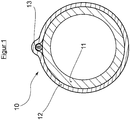
- This pipeline 10 initially comprises an inner load-bearing core tube 11 made of plastic with a lumen through which the medium flows.
- the core tube 11 is surrounded all around by a protective jacket 12, which consists of a plastic material with a higher mechanical strength, higher abrasion resistance, etc.
- This outer protective jacket 12 is extruded onto the core tube 11, for example.
- the outer protective jacket 12 surrounds the core tube almost everywhere without a gap, but a unit of measuring lines 13 in the form of a cable or the like is laid in one or more regions of the circumference.
- This unit of measuring lines 13 is used for resistance measurement for the detection and location of damaged areas and leaks used the invention. For the sake of easier handling in the manufacture of the pipeline 10, these several measuring lines are generally combined in one cable to form a unit 13, but this is not absolutely necessary for the function.
- the mentioned unit of measuring lines 13 is as from Figure 1 It can be seen below the outer casing of the pipeline by the protective jacket 12, so that the unit is also protected against mechanical influences by the protective jacket, but if the protective jacket is damaged, moisture can reach the measuring lines from the outside from the ground.
- the measuring lines 13 are laid on the core tube 11, which simplifies the manufacture of the tube 10, since the core tube 11 can then be extruded first, then the measuring lines 13 can be attached to it, and then the protective jacket 12 extruded so that this both the core tube 11 and also covers the measuring lines 13.
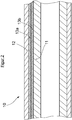
- Figure 2 shows a simplified longitudinal section of a in Figure 1
- the pipeline 10 shown from the front side shows on the one hand the inner core tube 11 and the outer protective jacket 12 applied to this inner core tube 11
- the unit of measuring lines 13 has at least two conductors, namely a first completely insulated conductor 13 a made of a comparatively low-resistance wire such as copper or the like and a second only partially insulated conductor 13 b made of a wire made of a material with a higher specific resistance than the first conductor 13 a, for example made of a chromium-nickel alloy.
- This second electrical conductor 13 b is the actual measuring line and is also referred to hereinafter as a sensor wire.
- the first electrical conductor 13 a serves as a reference line and is also referred to hereinafter as a reference wire.
- Both the sensor wire 13 b and the reference wire 13 a preferably each have an additional feedback wire, which is shown in the schematic drawing Figure 2 is not shown for simplification.
- a unit of measuring lines each has four line wires, of which, however, the sensor wire 13 b and the reference wire 13 a are primarily important for the measuring function. Further details regarding the structure and functioning of the measuring lines will be described later with reference to the enlarged detail views according to the Figures 3 and 4th as well as the schematic representation of Figure 5 described in more detail.
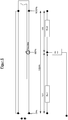
- Figure 3 shows in side view the detail of a single measuring line or sensor wire 13 b.
- This includes electrical insulation 132 consisting of a suitable plastic such as PTFE.
- the sensor wire 13 b has an internal wire 133 made of a comparatively high-resistance metal, for example made of a chromium-nickel alloy NiCr 8020, which for example has a diameter of approximately 0.5 mm.
- the electrical insulation 132 is how to get in Figure 3 interrupted by perforations 131 at several points at regular intervals from each other, so that in the event of damage to the outer protective jacket, moisture from the soil surrounding the pipeline 10 can reach the inner wire 133 of the sensor wire, the resistance of which is measured according to the invention.
- FIG 4 shows in side view in detail a return wire 13 a, which is also referred to herein as the first conductor.
- This return wire 13 a also includes electrical insulation 134 consisting of a suitable plastic and also has an inner wire 135, which in this case, however, consists of a metallic material with comparatively good electrical conductivity, that is, a low-resistance metal such as a copper wire .
- the return wire 13 a has an electrical insulation 134 which completely insulates the wire, so there are no openings in the insulation, so that any moisture that penetrates if the pipeline 10 is damaged can damage the wire 135 Return wire 13 a can not wet.
- Figure 5 shows a variant of the invention in which the pipeline is at least partially, that is to say, for example in individual layers, electrically conductive.
- Monitoring is made possible by an ohmic resistance measurement between the perforated sensor wire 13 b and the pipeline 10 in which the medium flows. Since the two conductors are electrically insulated with an intact pipeline 10 with a protective jacket, there is a high insulation resistance between the sensor wire 13 b and the core tube 11.
- the protective jacket 12 is now damaged when the pipeline 10 is damaged, moisture can penetrate through the perforations 131 in the insulation 132 of the sensor wire 13 b and the resistance between the pipe (media tube) and the sensor wire 13 b is reduced.
- the location of the damaged area can now be carried out according to the principle of the unloaded voltage divider.
- the resistance wire of the sensor wire 13 b forms a series resistance (loop resistance Rges), the size of which is ultimately determined by the length of the tube and the wire resistance built into it.
- a damaged point in the pipe system represents a connection between the sensor wire and the media pipe and divides the loop resistance into sections R (x1) from the start of the pipe (0% of the length) to the fault and section R (x2) from the fault to the pipe end (100 % of length).
- the two partial resistors R (x1) and R (x2) are directly dependent on the location of the moisture penetration. If a voltage is applied to the sensor loop 13 b, in the event of a fault, the conductive moisture transfers a partial voltage value that depends on the location to the media tube. Electrically speaking, the media tube takes over the function of the third connection, similar to the wiper connection of a potentiometer.
- the measured partial tension (x% of the total tension) is directly proportional to the location of the moisture penetration (x% of the total length).
- the advantages of the solution according to the invention are that the entire pipe system can be monitored. No electronic components are required.
- crimp sleeves can be used for simple sleeve assembly.
- Sensor loop monitoring can be carried out over the entire network. The location is possible even with small damaged areas and there is a high sensitivity. Safe and easy location of initial errors is possible.
- the pipe length can easily be determined by loop measurement.
- An arrangement according to the invention with a NiCr wire system as a return wire 13 a can be checked, for example, by measuring the continuity of the wire loop, the value being between 0.1 and 10 kOhm, for example.
- the measured value must correspond to the route length.
- the values in the forward and return should be approximately the same.
- An insulation measurement is also carried out between the wire loop and the media pipe, a high-resistance value in the range of, for example, more than 10 Mohm per 1000 m of pipeline being measured.
- the measurements are preferably carried out using a special insulation measuring device, for example LANCIER monitoring "PipeCheck" or isoplus “IPS-HST” or the like.
- the mode of operation here is similar to that previously used with Figure 5 variant described, but with the difference that the example of Figure 6 is a non-conductive pipeline and therefore the otherwise conductive media pipe is replaced by a conductive reference wire 15.
- the sensor wire 13 b is connected to a return wire 13 a guided in the opposite direction along the pipeline 10 to form a first measuring loop.
- a second measuring loop is formed by a reference wire 15, which is also connected to a return wire 16 guided in the opposite direction along the pipeline 10.
- the conductive reference wire 15 can consist, for example, of a copper wire, which in particular can be tin-plated and coated with a fleece. In order to check the continuity of the reference wire 15, it is connected to an insulated return wire 16 to form a measuring loop, which can be checked for continuity by a measuring device.
- This variant thus results in two measuring loops, the first measuring loop consisting of sensor wire 13 a and return wire 13 b and the second measuring loop consisting of reference wire 15 and return wire 16.
- the first measuring loop consisting of sensor wire 13 a and return wire 13 b
- the second measuring loop consisting of reference wire 15 and return wire 16.
- the reference wire 15 also comes into contact with moisture from the ground.
Abstract
Die vorliegende Erfindung betrifft eine Anordnung umfassend eine Rohrleitung (10) mit einer Einrichtung zur Überwachung der Rohrleitung auf Beschädigung oder Leckagen, umfassend einen ersten sich in der Rohrleitung etwa in Längsrichtung erstreckenden elektrischen Leiter (13 a) und einen zweiten sich in der Rohrleitung etwa in Längsrichtung erstreckenden elektrischen Leiter (13 b), eine äußere Schutzmantelschicht (12), die die elektrischen Leiter zur Umgebung hin elektrisch isoliert, eine Spannungsquelle, um die elektrischen Leiter mit einer Spannung zu beaufschlagen sowie eine Messvorrichtung, mittels derer ein Stromfluss durch die elektrischen Leiter und/oder deren elektrischer Widerstand messbar ist, wobei innerhalb der Rohrleitung wenigstens zwei elektrische Leiter (13 a, 13 b) angeordnet sind, welche aus Materialien mit jeweils unterschiedlichen spezifischen elektrischen Widerständen bestehen, wobei erfindungsgemäß ein erster elektrischer Leiter (13 a) einen Draht mit einer durchgehenden elektrischen Isolierung umfasst und ein zweiter elektrischer Leiter (13 b) einen Draht mit einer elektrischen Isolierung umfasst, wobei die elektrische Isolierung des zweiten Leiters (13 b) an mehreren Stellen, jeweils in definierten Abständen voneinander durchbrochen, insbesondere perforiert ist und wobei die Rohrleitung (10) ein Kernrohr (11) mit mindestens einer tragenden Schicht aus Kunststoff umfasst.The invention relates to an arrangement comprising a pipeline (10) with a device for monitoring the pipeline for damage or leaks, comprising a first electrical conductor (13 a) extending approximately in the longitudinal direction in the pipeline and a second one in the pipeline approximately in Longitudinally extending electrical conductor (13 b), an outer protective layer (12), which electrically isolates the electrical conductor from the environment, a voltage source to apply a voltage to the electrical conductor and a measuring device by means of which a current flow through the electrical conductor and / or whose electrical resistance can be measured, wherein at least two electrical conductors (13 a, 13 b) are arranged within the pipeline, which consist of materials with different specific electrical resistances, a first electrical conductor (13 a) according to the invention comprising a wire with a continuous existing electrical insulation and a second electrical conductor (13 b) comprises a wire with electrical insulation, the electrical insulation of the second conductor (13 b) being broken through, in particular perforated, at several points, in each case at defined intervals, and wherein the pipeline (10) comprises a core tube (11) with at least one load-bearing layer made of plastic.
Description
Die vorliegende Erfindung betrifft eine Anordnung umfassend eine Rohrleitung mit einer Einrichtung zur Überwachung der Rohrleitung auf Beschädigung oder Leckagen, umfassend einen ersten sich in der Rohrleitung etwa in Längsrichtung erstreckenden elektrischen Leiter und einen zweiten sich in der Rohrleitung etwa in Längsrichtung erstreckenden elektrischen Leiter, eine äußere Schutzmantelschicht, die die elektrischen Leiter zur Umgebung hin elektrisch isoliert, eine Spannungsquelle, um die elektrischen Leiter mit einer Spannung zu beaufschlagen sowie eine Messvorrichtung, mittels derer ein Stromfluss durch die elektrischen Leiter und/oder deren elektrischer Widerstand messbar ist, wobei innerhalb der Rohrleitung wenigstens zwei elektrische Leiter angeordnet sind, welche aus Materialien mit jeweils unterschiedlichen spezifischen elektrischen Widerständen bestehen.The present invention relates to an arrangement comprising a pipeline with a device for monitoring the pipeline for damage or leaks, comprising a first electrical conductor extending approximately in the longitudinal direction in the pipeline and a second electrical conductor extending approximately longitudinally in the pipeline, an outer Protective sheath layer, which electrically isolates the electrical conductors from the environment, a voltage source to apply a voltage to the electrical conductors, and a measuring device by means of which a current flow through the electrical conductors and / or their electrical resistance can be measured, at least within the pipeline Two electrical conductors are arranged, which consist of materials with different specific electrical resistances.
In der
Die
Aus der
Die
In der
Die
Die Aufgabe der vorliegenden Erfindung besteht darin, eine Anordnung umfassend eine Rohrleitung mit einer Einrichtung zur Überwachung der Rohrleitung auf Leckagen mit den Merkmalen der eingangs genannten Gattung zur Verfügung zu stellen, welche konstruktiv einfach aufgebaut ist und sowohl eine effektive Überwachung der Rohrleitung auf Leckagen ermöglicht als auch eine Ortung der Stelle, an der die Leckage aufgetreten ist.The object of the present invention is to provide an arrangement comprising a pipeline with a device for monitoring the pipeline for leaks with the features of the type mentioned at the outset, which is structurally simple and enables both effective monitoring of the pipeline for leaks and also a location of the point at which the leak occurred.
Die Lösung dieser Aufgabe liefert eine Anordnung der eingangs genannten Gattung mit den Merkmalen des Anspruchs 1.The solution to this problem is provided by an arrangement of the type mentioned at the beginning with the features of claim 1.
Erfindungsgemäß ist vorgesehen, dass ein erster elektrischer Leiter einen Draht mit einer durchgehenden elektrischen Isolierung umfasst und ein zweiter elektrischer Leiter einen Draht mit einer elektrischen Isolierung umfasst, wobei die elektrische Isolierung des zweiten Leiters an mehreren Stellen, jeweils in definierten Abständen voneinander durchbrochen, insbesondere perforiert ist und dass die Rohrleitung in Kernrohr mit mindestens einer tragenden Schicht aus Kunststoff umfasst.According to the invention, it is provided that a first electrical conductor comprises a wire with continuous electrical insulation and a second electrical conductor comprises a wire with electrical insulation, the electrical insulation of the second conductor being broken through, in particular perforated, at a plurality of locations, in each case at defined intervals from one another and that the pipeline in the core tube comprises at least one load-bearing layer made of plastic.
Die vorliegende Erfindung bezieht sich somit auf Rohrleitungen, die zumindest in wesentlichen Bereichen aus Kunststoff bestehen. Im Gegensatz dazu weisen Rohre für den Transport von Fernwärme, wie sie in einigen der eingangs genannten Schriften aus dem Stand der Technik beschrieben werden, zumeist ein Kernrohr aus Metall auf. In diesem Fall ist das Kernrohr der Rohrleitung selbst elektrisch leitend, während dies bei einem erfindungsgemäßen Kernrohr aus Kunststoff nicht der Fall ist. Die erfindungsgemäßen Rohrleitungen bestehen, wie dies bei Kunststoffrohren häufig der Fall ist, aus mehreren Schichten, die sich in ihren jeweiligen Werkstoffen und auch in ihrer Funktion für die Rohrleitung unterscheiden können. Bei einem erfindungsgemäßen Kunststoffrohr können mehrere Schichten jeweils aus Kunststoff bestehen und das Kunststoffrohr kann auch ausschließlich aus Kunststoff bestehen. Von der vorliegenden Erfindung umfasst sind aber auch Kunststoffrohrleitungen, bei denen einzelne Schichten elektrisch leitend sind und nicht oder nicht ausschließlich aus Kunststoff bestehen. Dies können beispielsweise metallische Barriereschichten sein, die zum Beispiel aus Aluminium bestehen können und für den Schutz gegen Chemikalien verwendet werden. Diese Barriereschichten haben häufig eine vergleichsweise geringe Schichtdicke und sind als so genannte Funktionsschichten, nicht aber als tragende Schichten eines Kunststoffrohres anzusehen. Dies können beispielsweise auch abrasionsresistente Schichten sein, bei denen Partikel aus unterschiedlichen, beispielsweise mineralischen oder metallischen Werkstoffen in die Schicht eingebettet werden, so dass sich auch deren Leitfähigkeit verändert. Diese beiden Beispiele sind erläuternd und nicht einschränkend zu verstehen und dienen dazu, zu verdeutlichen, was unter einem Rohr, welches "im Wesentlichen aus Kunststoff besteht, im Rahmen der vorliegenden Erfindung zu verstehen ist. Ein solches Rohr, welches in diesem Sinne als "im Wesentlichen aus Kunststoff" besteht, wird aufgrund des Materials des Kernrohrs und/oder der tragenden Rohrschichten in der Technik als Kunststoffrohr bezeichnet.The present invention thus relates to pipelines which consist at least in essential areas of plastic. In contrast to this, pipes for the transport of district heating, as described in some of the prior art documents mentioned above, usually have a metal core pipe. In this case, the core pipe of the pipeline itself is electrically conductive, while this is not the case with a plastic core pipe according to the invention. The pipes according to the invention, as is often the case with plastic pipes, consist of several layers which can differ in their respective materials and also in their function for the pipe. In a plastic pipe according to the invention, several layers can each consist of plastic and the plastic pipe can also consist exclusively of plastic. However, the present invention also includes plastic pipelines in which individual layers are electrically conductive and do not consist, or not exclusively, of plastic. These can be metallic barrier layers, for example Example can be made of aluminum and used for protection against chemicals. These barrier layers often have a comparatively small layer thickness and are to be regarded as so-called functional layers, but not as load-bearing layers of a plastic pipe. These can also be, for example, abrasion-resistant layers in which particles of different, for example mineral or metallic materials are embedded in the layer, so that their conductivity also changes. These two examples are to be understood as illustrative and not restrictive and serve to clarify what is to be understood in the context of the present invention by a tube which "essentially consists of plastic. Such a tube, which in this sense is referred to as" im Essentially made of plastic "is referred to in the art as a plastic tube due to the material of the core tube and / or the supporting tube layers.
Die beiden elektrischen Leiter sind geeignet, als Ortungsdrähte eine Fehlerstelle bei Beschädigung der Rohrleitung zu detektieren und genau zu orten. Rohrleitungen dieser Art werden im Erdreich oder gegebenenfalls auch unter Wasser verlegt und sie bestehen in der Regel entweder aus mehreren Schichten aus Kunststoff oder es handelt sich um Rohre aus Verbundmaterialien mit Schichten aus Kunststoff und gegebenenfalls weiteren Materialien, beispielsweise dünnen metallischen Folien, die als Barriereschichten dienen, um das Austreten von Flüssigkeiten aus der Rohrleitung in das umgebende Erdreich zu verhindern. Derartige Rohrleitungen weisen im allgemeinen ein ein- oder mehrschichtiges Kernrohr aus Kunststoff auf, das eine tragende Schicht oder einen Schichtverbund bildet und beispielsweise aus Kunststoffen wie Polyolefinen oder dergleichen bestehen kann. Da die Rohrleitung in ihrem äußeren Randbereich erfahrungsgemäß besonderen mechanischen Belastungen unterliegt, insbesondere auch in den Fällen, in denen die Rohrleitung in einem grabenlosen Verlegeverfahren in das Erdreich eingezogen wird, ist das Kernrohr zumeist von einem Schutzmantel umgeben, der aus einem besonders verschleißfesten, abrasionsfesten Kunststoff mit hoher Beständigkeit gegen Risswachstum etc. besteht. Dieser Schutzmantel kann nach der Fertigung des Rohres auf das Kernrohr aufextrudiert werden oder alternativ auch bei der Herstellung des Kernrohrs durch Coextrusion aufgebracht werden. Das Aufextrudieren hat gewisse Vorteile, unter anderem da sich dann dieser Schutzmantel abschälen lässt, wenn zwei Rohrstränge einer solchen Rohrleitung miteinander verschweißt werden müssen.The two electrical conductors are suitable as location wires to detect and precisely locate a fault location when the pipeline is damaged. Pipes of this type are laid in the ground or, if appropriate, also under water and they usually consist either of several layers of plastic or they are pipes made of composite materials with layers of plastic and possibly other materials, for example thin metallic foils, which serve as barrier layers to prevent liquids from escaping from the pipeline into the surrounding soil. Such pipelines generally have a single-layer or multi-layer plastic core tube, which forms a load-bearing layer or a layer composite and can for example consist of plastics such as polyolefins or the like. Since experience has shown that the outer edge of the pipeline is subject to special mechanical loads, especially in cases where the pipeline is drawn into the ground using a trenchless installation method, the core pipe is usually surrounded by a protective jacket made of a particularly wear-resistant, abrasion-resistant plastic with high resistance to crack growth etc. This protective jacket can be extruded onto the core tube after the production of the tube or, alternatively, can also be applied during the production of the core tube by coextrusion. Extrusion has certain advantages, among other things because this protective jacket can be peeled off if two pipe strings of such a pipeline have to be welded together.
Dieser Schutzmantel hat somit die Aufgabe, das Kernrohr und gegebenenfalls weitere innere Rohrschichten gegen mechanische, von außen einwirkende Einflüsse sowie Witterungseinflüsse zu schützen. Wenn eine Beschädigung dieses Schutzmantels auftritt, erhöht sich die Gefahr eines Schadens auch am Kernrohr, da dieses dann ungeschützt ist und weniger widerstandsfähig ist gegen mechanische Belastungen und Witterungseinflüsse ist, so dass die Gefahr einer Leckage besteht, durch die dann ein für die Umwelt schädliches Fluid, welches in der Rohrleitung transportiert wird, unkontrolliert in die Umgebung, d.h. in das Erdreich oder ein Gewässer gelangen kann. Daher ist es sehr wichtig, nicht nur sehr frühzeitig zu erfahren, wenn eine solche Leckage an der Rohrleitung auftritt, sondern diese auch möglichst genau lokalisieren zu können, da die Rohrleitung im Erdreich verlegt ist und daher eine Reparatur Grabungsarbeiten erfordert, um sich einen Zugang zu der Leckagestelle zu verschaffen. Da diese Erdarbeiten aufwändig sind, ist man naturgemäß bestrebt, diese auf ein Minimum zu beschränken, wozu ein genaues Lokalisieren der Leckagestelle erforderlich ist.This protective jacket therefore has the task of protecting the core tube and, if appropriate, further inner tube layers against mechanical external influences and weather influences. If this protective jacket is damaged, the risk of damage to the core tube also increases, since this is then unprotected and less resistant is against mechanical loads and weather influences, so that there is a risk of leakage, through which a fluid which is harmful to the environment and which is transported in the pipeline can then get into the environment in an uncontrolled manner, ie into the ground or into a body of water. It is therefore very important not only to find out very early if such a leak occurs on the pipeline, but also to be able to locate it as precisely as possible, since the pipeline is buried in the ground and therefore requires excavation work to gain access to it to provide the leakage point. Since this earthwork is complex, efforts are naturally made to keep it to a minimum, which requires an exact location of the leakage point.
Die Erfahrung zeigt, dass das aus dem Stand der Technik bekannte Einextrudieren von elektrischen Leitern in den Kunststoff einer Schicht der Rohrleitung, sei es in das Kernrohr oder in äußere Schutzschichten, aufwändig und daher teuer ist. Es ist daher vorteilhaft, die elektrischen Leiter für die Ortung unter dem Schutzmantel, aber auf dem Umfang des Kernrohrs (also nicht in dem Kunststoff des Kernrohrs), zu verlegen. Dies ermöglicht bei der Herstellung zunächst die (quasi endlose) Extrusion des Kernrohrs in einer Extrusionslinie, danach die Aufbringung und gegebenenfalls Befestigung der elektrischen Leiter auf dem Kernrohrs und danach die Aufbringung des Schutzmantels, beispielsweise in einem erneuten Extrusionsvorgang durch Aufextrudieren, so dass der Schutzmantel die beiden elektrischen Leiter und auch den Kernrohrs überzieht und gleichzeitig die beiden elektrischen Leiter mechanisch in der mehrschichtigen Rohrleitung sicher fixiert. Die beiden elektrischen Leiter liegen dann also zwischen dem Kernrohr und dem Schutzmantel und sind zum einen durch den Schutzmantel gegen mechanische Einflüsse geschützt. Außerdem werden sie durch den Vorgang der Umhüllung von der Schutzmantelschicht so eng überzogen, dass sie absolut lagefixiert sind und keinen Bewegungsspielraum in der fertigen Rohrleitung haben.Experience shows that the extrusion of electrical conductors known from the prior art into the plastic of a layer of the pipeline, be it into the core pipe or into outer protective layers, is complex and therefore expensive. It is therefore advantageous to lay the electrical conductors for the location under the protective jacket, but on the circumference of the core tube (ie not in the plastic of the core tube). During manufacture, this enables the (quasi endless) extrusion of the core tube in an extrusion line, then the application and, if necessary, attachment of the electrical conductors to the core tube and then the application of the protective jacket, for example in a renewed extrusion process by extrusion, so that the protective jacket covers both electrical conductors and also the core tube and at the same time mechanically fixes the two electrical conductors securely in the multilayer pipeline. The two electrical conductors are then between the core tube and the protective jacket and are protected on the one hand by the protective jacket against mechanical influences. In addition, the protective coating layer covers them so closely through the process of sheathing that they are absolutely fixed in position and have no freedom of movement in the finished pipeline.
Die beiden elektrischen Leiter können gemäß der Erfindung mit einer Gleichspannung beaufschlagt werden und wenn eine Leckage auftritt oder der äußere Schutzmantel der Rohrleitung fehlerhaft ist, kann man dies nicht nur messen und anzeigen, sondern man kann über eine Ohm'sche Widerstandsmessung auch diejenige Stelle, an der die Leckage aufgetreten ist, genau einmessen. Dies wird erfindungsgemäß dadurch möglich, dass man zwei elektrische Leiter als Ortungsdrähte verwendet. Der erste dieser beiden Leiter dient dabei quasi als Referenzleiter. Es wird bei Aufgabe einer Gleichspannung der jeweilige elektrische Widerstand beider Leiter mittels einer geeigneten Messvorrichtung gemessen und die Widerstandswerte beider Leiter werden durch die Messvorrichtung miteinander verglichen. Wenn nun eine Leckage an der Rohrleitung auftritt, ändert sich der Widerstand des zweiten Leiters, was die Messvorrichtung detektiert und woraus dann auf eine Leckage geschlossen werden kann.According to the invention, the two electrical conductors can be supplied with a DC voltage and if a leakage occurs or the outer protective jacket of the pipeline is defective, this can not only be measured and displayed, but also the point can be measured using an ohmic resistance measurement measure the leakage exactly. According to the invention, this is made possible by using two electrical conductors as locating wires. The first of these two conductors serves as a reference conductor. When a direct voltage is applied, the respective electrical resistance of both conductors is measured by means of a suitable measuring device and the resistance values of both conductors are compared with one another by the measuring device. If there is a leak in the pipeline, the resistance of the second conductor changes, what the measuring device detects and from which a leak can then be concluded.
Gemäß einer bevorzugten Weiterbildung der Erfindung umfasst ein zweiter elektrischer Leiter einen Draht mit einer elektrischen Isolierung, wobei die elektrische Isolierung an mehreren Stellen, jeweils in definierten Abständen voneinander durchbrochen, insbesondere perforiert ist. Wenn nun der Schutzmantel der Rohrleitung beschädigt ist, kann Feuchtigkeit aus dem Erdreich an die Leiter gelangen und auch direkt an den leitenden Draht des zweiten Drahts gelangen, da dessen Isolierung ja stellenweise perforiert ist. Infolgedessen ändert sich dann der gemessene Widerstandswert für den zweiten Draht, während derjenige des isolierten ersten Referenzdrahtes gleich bleibt. Aus der Messung des Widerstandswerts kann die Messvorrichtung auch ableiten, an welcher Stelle der Rohrleitung die Leckage aufgetreten ist, so dass eine genaue Ortung möglich ist. Es ist dann sehr einfach für einen Bautrupp, der sich direkt an die Stelle begeben kann, wo die Leckage der Rohrleitung vorliegt und dort die Reparatur mit vergleichsweise geringem Aufwand beim Freigraben der Rohrleitung vornehmen kann.According to a preferred development of the invention, a second electrical conductor comprises a wire with electrical insulation, the electrical insulation being broken through, in particular perforated, at a plurality of locations, in each case at defined intervals from one another. If the protective jacket of the pipeline is now damaged, moisture can get from the ground to the conductors and also directly to the conductive wire of the second wire, since its insulation is perforated in places. As a result, the measured resistance value for the second wire then changes, while that of the insulated first reference wire remains the same. From the measurement of the resistance value, the measuring device can also derive at which point in the pipeline the leakage occurred, so that an exact location is possible. It is then very easy for a construction team that can go directly to the point where the pipeline is leaking and can carry out the repair there with comparatively little effort when digging the pipeline free.
Gemäß einer bevorzugten Weiterbildung der Erfindung umfasst ein erster der beiden elektrischen Leiter beispielsweise einen Kupferdraht und ein zweiter elektrischer Leiter umfasst ein metallisches Material mit einem höheren spezifischen Widerstand als Kupferdraht. Beispielsweise kann man für den zweiten elektrischen Leiter einen Draht aus einer Chrom-Nickel-Legierung oder anderen geeigneten Legierungen verwenden.According to a preferred development of the invention, a first of the two electrical conductors comprises, for example, a copper wire and a second electrical conductor comprises a metallic material with a higher specific resistance than copper wire. For example, a wire made of a chromium-nickel alloy or other suitable alloys can be used for the second electrical conductor.
Gemäß einer bevorzugten Weiterbildung der Erfindung umfasst der erste elektrische Leiter, also beispielsweise der Referenzleiter, einen Draht mit einer durchgehenden elektrischen Isolierung. Der Widerstand dieses Referenzleiters bleibt somit gleich, während sich bei auftretender Feuchtigkeit der Widerstand des zweiten elektrischen Leiters ändert. Vorteilhaft bei der erfindungsgemäßen Lösung ist, dass bereits eine Beschädigung der äußeren Schutzmantelschicht der Rohrleitung ausreicht, damit das Detektionssystem anspricht, denn bereits dann kann Feuchtigkeit aus dem umgebenden Erdreich an den zweiten elektrischen Leiter gelangen, dessen Isolierung nicht durchgehend ist. Die innere Schicht der Rohrleitung, das heißt das Kernrohr ist dann in der Regel noch intakt, es tritt somit keine Flüssigkeit aus der Rohrleitung in die Umgebung aus. Somit liegt noch keine Leckage der Rohrleitung im eigentlichen Sinne vor, sondern nur eine Beschädigung des äußeren Schutzmantels. Die erfindungsgemäße Einrichtung detektiert somit diesen Schaden an der Rohrleitung, bevor ein Umweltschaden entsteht. Es ist somit anders als bei bekannten Systemen nicht so, dass die Detektion über aus der Rohrleitung selbst austretende Flüssigkeit erfolgen muss.According to a preferred development of the invention, the first electrical conductor, that is to say for example the reference conductor, comprises a wire with continuous electrical insulation. The resistance of this reference conductor therefore remains the same, while the resistance of the second electrical conductor changes when moisture occurs. An advantage of the solution according to the invention is that damage to the outer protective jacket layer of the pipeline is sufficient for the detection system to respond, because even then moisture from the surrounding earth can reach the second electrical conductor, the insulation of which is not continuous. The inner layer of the pipeline, that is to say the core pipe, is then generally still intact, so that no liquid escapes from the pipeline into the environment. This means that there is no leakage in the pipeline as such, but only damage to the outer protective jacket. The device according to the invention thus detects this damage to the pipeline before environmental damage occurs. In contrast to known systems, it is not the case that the detection must be carried out using liquid emerging from the pipeline itself.
Gemäß einer bevorzugten Weiterbildung der Erfindung ist vorgesehen, dass die elektrischen Leiter innerhalb der Rohrleitung etwa in Längsrichtung jeweils hin und zurück verlaufen. Man verwendet bei dieser Variante eine Fühlerader, die dem oben erwähnten zweiten Leiter entspricht und daher mit einer teilweise durchbrochenen Isolierung versehen ist, und eine Rückführader, die mit einer vollständigen Isolierung versehen ist. In dem Fall, dass es sich um eine zumindest teilweise elektrisch leitende Rohrleitung handelt, beispielsweise eine Rohrleitung aus Kunststoff mit wenigstens einer metallischen Schicht, dann kann man mit Fühlerader und einer Rückführader, das heißt im Prinzip zwei sich am Rohr in Längsrichtung hin und zurück erstreckenden Leitungen die Messung vornehmen, da die Rohrleitung selbst die Funktion eines dritten Anschlusses übernimmt.According to a preferred development of the invention, it is provided that the electrical conductors run back and forth within the pipeline approximately in the longitudinal direction. In this variant, a sensor wire is used, which corresponds to the second conductor mentioned above and is therefore provided with partially broken insulation, and a return wire which is provided with complete insulation. In the event that it is an at least partially electrically conductive pipeline, for example a plastic pipeline with at least one metallic layer, then one can with a sensor wire and a return wire, that is, in principle, two that extend back and forth on the pipe in the longitudinal direction Cables carry out the measurement, since the pipeline itself takes on the function of a third connection.
Sofern es sich jedoch um ein nicht elektrisch leitendes Rohrleitungssystem handelt, ist es bevorzugt so, dass man eine Fühlerader mit Rückführader und zusätzlich noch eine Referenzader mit Rückführader verwendet, das heißt es handelt sich dann um insgesamt vier Leitungen, die zwei Messschleifen bilden und jeweils paarweise an der Rohrleitung über die zu messende Wegstrecke hin und zurück geführt sind. Mit dieser Anordnung von vier Leitungen kann man auch bei einer reinen Kunststoffrohrleitung über Widerstandsmessungen den Ort der Fehlerstelle genau bestimmen.If, however, it is a non-electrically conductive piping system, it is preferred to use a sensor wire with a feedback wire and also a reference wire with a feedback wire, i.e. there are a total of four lines that form two measuring loops and each in pairs are routed back and forth on the pipeline over the distance to be measured. With this arrangement of four lines, the location of the fault location can be precisely determined even with a pure plastic pipeline using resistance measurements.
Gemäß einer bevorzugten Weiterbildung der Erfindung sind der erste elektrische Leiter mit seiner Isolierung und der zweite elektrische Leiter mit seiner durchbrochenen Isolierung oder sofern vorhanden mehr als zwei funktional zusammenwirkende Leiter (beispielsweise vier Leitungen wie oben erwähnt) eines Messsystems jeweils mit einer gemeinsamen Umhüllung umgeben, so dass sie eine Leitereinheit mit Umhüllung nach Art eines Kabels bilden. Diese Umhüllung hat insbesondere fertigungstechnische Vorteile, da sich so eine Einheit ergibt, die sich bei der Fertigung des Kunststoffrohres in einer Extrusionslinie handhaben lässt. Man kann beispielsweise so vorgehen, dass man zunächst das Kernrohr über eine erste Extrusionsvorrichtung mit Extruderdüse extrudiert, dann die Leitereinheit als Kabel beispielsweise von einer Rolle abwickelt und einer zweiten Extrusionsvorrichtung mit Extruderdüse zuführt, in der der Schutzmantel auf das Kernrohr aufextrudiert wird, derart, dass das Kabel dann auf dem Kernrohr liegt und von der Schutzmantelschicht beim Aufextrudieren mit überzogen wird.According to a preferred development of the invention, the first electrical conductor with its insulation and the second electrical conductor with its broken insulation or, if present, more than two functionally interacting conductors (for example four lines as mentioned above) of a measuring system are each surrounded by a common sheath, so that they form a conductor unit with a sheath like a cable. This sheathing has particular advantages in terms of production technology, since this results in a unit that can be handled in an extrusion line during the manufacture of the plastic tube. One can proceed, for example, by first extruding the core tube via a first extrusion device with extruder nozzle, then unwinding the conductor unit as a cable, for example from a roll, and feeding it to a second extrusion device with extruder nozzle in which the protective jacket is extruded onto the core tube in such a way that the cable then lies on the core tube and is covered by the protective jacket layer during extrusion.
Gemäß einer bevorzugten Weiterbildung der Erfindung ist es von Vorteil, wenn die Anordnung zwei oder mehrere über den Umfang der Rohrleitung jeweils mit Abstand zueinander angeordnete und jeweils etwa in Längsrichtung der Rohrleitung unter dem Schutzmantel verlaufend angeordnete Einheiten von wenigstens jeweils zwei elektrischen Leitern umfasst. Diese Variante ist insbesondere bei Rohrleitungen mit einem größeren Rohrdurchmesser zu empfehlen. Bei diesen kann es nämlich vorkommen, dass es bei einer Beschädigung der Rohrleitung verhältnismäßig lange dauert, bis Feuchtigkeit aus dem Erdreich an die Leiter gelangt, was auch von der jeweiligen Lage der Rohrleitung nach der Verlegung abhängt, beispielsweise, ob sich die Leiter in einem oberen, seitlichen oder unteren Umfangsbereich der Rohrleitung befinden. Sind jedoch über den Umfang verteilt mehrere Einheiten von Leitungen vorhanden, über die detektiert wird, dann wird mit hoher Sicherheit eine dieser Einheiten ansprechen und die Reaktion auf eine Beschädigung erfolgt in jedem Fall rascher. Rohrleitungen mit größerem Rohrdurchmesser im Sinne dieser Variante der Erfindung sind beispielsweise solche mit einem Rohrdurchmesser von mehr als 10 cm. Der Rohrdurchmesser von Rohrleitungen aus Kunststoff dieser Art kann beispielsweise variieren von wenigen Zentimetern bis zu einem Meter oder mehreren Metern Durchmesser. Hier gibt es bei der Anwendbarkeit der erfindungsgemäßen Lösung prinzipiell keine Einschränkungen, außer dass es empfehlenswert ist, bei Rohrleitungen mit größeren Durchmesser am Umfang mehrere beabstandete Leitereinheiten für die Detektion eines Schadens an der Rohrleitung vorzusehen.According to a preferred further development of the invention, it is advantageous if the arrangement has two or more spaced-apart arrangements around the circumference of the pipeline and each approximately in the longitudinal direction of the pipeline under the protective jacket running units of at least two electrical conductors each. This variant is particularly recommended for pipes with a larger pipe diameter. In the case of these, it can happen that if the pipeline is damaged, it takes a relatively long time for moisture to reach the conductors from the ground, which also depends on the respective position of the pipeline after installation, for example whether the conductors are in an upper one , lateral or lower peripheral area of the pipeline. If, however, there are several units of lines distributed over the circumference that are used for detection, then one of these units will respond with high certainty and the reaction to damage is in any case quicker. Pipes with a larger pipe diameter in the sense of this variant of the invention are, for example, those with a pipe diameter of more than 10 cm. The pipe diameter of plastic pipes of this type can vary, for example, from a few centimeters to a meter or several meters in diameter. In principle, there are no restrictions on the applicability of the solution according to the invention, except that it is advisable to provide a plurality of spaced-apart conductor units for the detection of damage to the pipeline in the case of pipes with a larger diameter on the circumference.
Gegenstand der vorliegenden Erfindung ist weiterhin ein Verfahren zur Überwachung einer Rohrleitung auf Beschädigung oder Leckagen, wobei innerhalb der Rohrleitung auf einem Kernrohr und unterhalb einer äußeren Schutzmantelschicht wenigstens zwei elektrische Leiter angeordnet sind, welche aus Materialien mit jeweils unterschiedlichen spezifischen elektrischen Widerständen bestehen, wobei die elektrischen Leiter durch die äußere Schutzmantelschicht zur Umgebung hin elektrisch isoliert sind, wobei mittels einer Spannungsquelle beide elektrischen Leiter mit einer Spannung beaufschlagt werden und mittels einer Messvorrichtung ein Stromfluss durch die elektrischen Leiter und/oder deren jeweiliger elektrischer Widerstand gemessen wird und wobei bei einer Abweichung der gemessenen Werte von einem Sollwert eine Beschädigung der Rohrleitung detektiert wird.The present invention further relates to a method for monitoring a pipeline for damage or leaks, wherein at least two electrical conductors are arranged within the pipeline on a core tube and below an outer protective jacket layer, which are made of materials with different specific electrical resistances, the electrical Conductors are electrically insulated from the outside protective sheath layer to the environment, with a voltage source applying a voltage to both electrical conductors and a current flow through the electrical conductors and / or their respective electrical resistance being measured by means of a measuring device, and in the event of a deviation of the measured Damage to the pipeline is detected from a setpoint.
Vorzugsweise ist bei diesem Verfahren ein erster elektrischer Leiter vollständig elektrisch isoliert und ein zweiter elektrischer Leiter weist eine in bestimmten Bereichen mit regelmäßigen Abständen durchbrochene elektrische Isolierung auf und über die gemessenen Widerstands- und/oder Stromflusswerte wird die Stelle, an der die Beschädigung der Rohrleitung vorliegt, geortet.In this method, a first electrical conductor is preferably completely electrically insulated and a second electrical conductor has electrical insulation which is broken through at regular intervals in certain areas, and the location of the damage to the pipeline is determined via the measured resistance and / or current flow values , located.
Vorzugsweise wird bei dem vorgenannten Verfahren eine Anordnung verwendet, wie sie hierin zuvor beschrieben wurde.Preferably, an arrangement as described hereinbefore is used in the aforementioned method.
Die in den Unteransprüchen genannten Merkmale betreffen bevorzugte Weiterbildungen der erfindungsgemäßen Aufgabenlösung. Weitere Vorteile der Erfindung ergeben sich aus der nachfolgenden Detailbeschreibung.The features mentioned in the subclaims relate to preferred developments of the task solution according to the invention. Further advantages of the invention result from the following detailed description.
Nachfolgend wird die vorliegende Erfindung anhand von Ausführungsbeispielen unter Bezugnahme auf die beiliegenden Zeichnungen näher beschrieben. Dabei zeigen:
-
Figur 1 eine schematisch vereinfachte stirnseitige Ansicht einer erfindungsgemäßen Anordnung; -
Figur 2 eine Ansicht eines Längsschnitts durch eine erfindungsgemäße Anordnung; -
Figur 3 eine Ansicht des ersten Leiters, welcher in einer erfindungsgemäßen Rohrleitung verlegt ist; -
Figur 4 eine Ansicht des zweiten Leiters, welcher in einer erfindungsgemäßen Rohrleitung verlegt ist; -
Figur 5 eine schematische Darstellung zur Erläuterung der Ortung der schadhaften Stelle in einer mindestens teilweise elektrisch leitenden Rohrleitung; -
Figur 6 eine schematische Darstellung einer alternativen Variante der Erfindung, bei der die Widerstandsmessung bei einem nicht leitenden Rohrsystem erfolgt.
-
Figure 1 a schematically simplified front view of an arrangement according to the invention; -
Figure 2 a view of a longitudinal section through an arrangement according to the invention; -
Figure 3 a view of the first conductor which is laid in a pipeline according to the invention; -
Figure 4 a view of the second conductor, which is laid in a pipeline according to the invention; -
Figure 5 a schematic representation to explain the location of the damaged location in an at least partially electrically conductive pipeline; -
Figure 6 is a schematic representation of an alternative variant of the invention, in which the resistance measurement is carried out in a non-conductive pipe system.
Nachfolgend wird zunächst auf die
Die genannte Einheit von Messleitungen 13 befindet sich wie aus
The mentioned unit of measuring
Weitere Einzelheiten des Aufbaus und der Funktionsweise der erfindungsgemäßen Messung des Widerstands und der Leckortung werden nun nachfolgend unter Bezugnahme auf die schematische Darstellung gemäß
Zwischen Rohranfang und Rohrende bildet der Widerstandsdraht der Fühlerader 13 b einen Längswiderstand (Schleifenwiderstand Rges), dessen Größe letztendlich durch die Rohrlänge und den darin verbauten Drahtwiderstand bestimmt wird. Eine Schadstelle im Rohrsystem stellt eine Verbindung zwischen dem Fühlerader und dem Medienrohr dar und teilt den Schleifenwiderstand in die Abschnitte R(x1) vom Rohrbeginn (0% der Länge) bis zum Fehler und dem Abschnitt R(x2) vom Fehler bis zum Rohrende (100 % der Länge). Die beiden Teilwiderstände R(x1) und R(x2) sind direkt abhängig vom Ort der Durchfeuchtung. Legt man eine Spannung an die Fühlerschleife 13 b an, so überträgt im Fehlerfall die leitende Feuchtigkeit einen vom Ort abhängigen Spannungsteilwert auf das Medienrohr. Elektrisch gesehen übernimmt das Medienrohr die Funktion des dritten Anschlusses, ähnlich dem Schleiferanschluss eines Potentiometers. Die gemessene Teilspannung (x% der Gesamtspannung) ist direkt proportional zum Ort der Durchfeuchtung (x% der Gesamtlänge).Between the start and end of the tube, the resistance wire of the
In der Praxis findet man jedoch kaum idealisierte Verhältnisse vor, sondern hat es mit zusätzlichen Störkomponenten zu tun. Hierzu zählt unter anderem die Elementspannung (Ux), die sich aufgrund der verwendeten Metalle (beispielsweise Chrom-Nickel-Draht, Stahlrohr) als chemisches Spannungselement ausbildet. Die meisten der heute verwendeten Ortungsmessgeräte können jedoch derartige Störkomponenten relativ gut kompensieren, so dass bei hochohmigen Fehlern im MOhm-Bereich sehr gute Ortungsergebnisses erzielt werden. Aufgrund des physikalischen Prinzips des unbelasteten Spannungsteilers können nur einzelne Feuchtefehler lokalisiert werden. Mehrfachfehler sind bei dem hier beschriebenen System nicht ortbar. Hier kann bei passender Gerätetechnik der erste Fehlerort gespeichert werden, um dann von diesem aus zu weiteren Fehlern zu gelangen.In practice, however, there are hardly any idealized conditions; instead, it has to do with additional interference components. This includes the element voltage (Ux), which is formed as a chemical stress element due to the metals used (e.g. chrome-nickel wire, steel tube). Most of the location measuring devices used today, however, can compensate for such interference components relatively well, so that very good location results are achieved with high-resistance errors in the MOhm range. Due to the physical principle of the unloaded voltage divider, only individual moisture errors can be localized. Multiple errors cannot be located in the system described here. With the right device technology, the first fault location can be saved here, in order to then be able to reach further faults from there.
Die Vorteile der erfindungsgemäßen Lösung liegen darin, dass das gesamte Rohrsystem überwacht werden kann. Es werden keine elektronischen Komponenten benötigt. Beispielsweise durch Quetschhülsen kann eine einfache Muffenmontage erfolgen. Die Fühlerschleifenüberwachung kann über das gesamte Netz erfolgen. Die Ortung ist schon bei kleinen Schadstellen möglich und es besteht eine hohe Ansprechempfindlichkeit. Es ist eine sichere und einfache Ortung von Erstfehlern möglich. Die Rohrlänge kann einfach durch Schleifenmessung bestimmt werden.The advantages of the solution according to the invention are that the entire pipe system can be monitored. No electronic components are required. For example, crimp sleeves can be used for simple sleeve assembly. Sensor loop monitoring can be carried out over the entire network. The location is possible even with small damaged areas and there is a high sensitivity. Safe and easy location of initial errors is possible. The pipe length can easily be determined by loop measurement.
Die Überprüfung einer erfindungsgemäßen Anordnung mit einem NiCr-Draht-System als Rückführader 13 a kann beispielsweise über eine Durchgangsmessung der Drahtschleife erfolgen, wobei der Wert beispielsweise zwischen 0,1 und 10 kOhm liegt. Der Messwert muss umgerechnet mit der Trassenlänge übereinstimmen. Die Werte im Vor- und Rücklauf sollten annähernd gleich sein. Zwischen der Drahtschleife und dem Medienrohr erfolgt außerdem eine Isolationsmessung, wobei ein hochohmiger Wert im Bereich von beispielsweise mehr als 10 Mohm pro 1000 m Rohrleitung gemessen wird. Die Messungen werden vorzugsweise mit einem speziellen Isolationsmessgerät durchgeführt, beispielsweise LANCIER Monitoring "PipeCheck" oder isoplus "IPS-HST" oder dergleichen.An arrangement according to the invention with a NiCr wire system as a
Nachfolgend wird unter Bezugnahme auf die
Somit ergeben sich bei dieser Variante zwei Messschleifen, die erste Messschleife aus Fühlerader 13 a und Rückführader 13 b und die zweite Messschleife aus Referenzader 15 und Rückführader 16. Es sind somit insgesamt vier Leitungsadern vorhanden, die an der Rohrleitung, vorzugsweise zwischen Kernrohr 11 und Schutzmantel 12 verlegt werden können. Wenn nun eine Beschädigung des Schutzmantels 12 eintritt kommt die Fühlerader 13 b mit Feuchtigkeit aus dem Erdreich in Kontakt und der Widerstand in der Messschleife aus 13 a und 13 b sinkt. Ebenso kommt auch die Referenzader 15 mit Feuchtigkeit aus dem Erdreich in Kontakt. Wenn man an beide Messschleifen eine Spannung anlegt, kann man nun wieder wie oben bereits erläutert wurde die jeweiligen Widerstände R(x1) vom Beginn der Rohrleitung bis zur Fehlerstelle und R(x2) von der Fehlerstelle bis zum Rohrende bestimmen und aus den Teilwiderstände dann bestimmen, an welchem Punkt der Rohrleitung sich die Fehlerstelle befindet. In der Zeichnung
- 1010th
- RohrleitungPipeline
- 1111
- KernrohrCore tube
- 1313
- Einheit von MessleitungenUnit of measuring lines
- 1212
- SchutzmantelProtective jacket
- 13 a13 a
- erster elektrischer Leiterfirst electrical conductor
- 13 b13 b
- zweiter elektrischer Leiter/Fühleradersecond electrical conductor / sensor wire
- 131131
- PerforationenPerforations
- 132132
- Isolierunginsulation
- 133133
- innenliegender Drahtinternal wire
- 134134
- elektrische Isolierungelectrical insulation
- 135135
- innenliegender Drahtinternal wire
- 1515
- ReferenzanderReference other
- 1616
- RückführaderReturn line
Claims (12)
Applications Claiming Priority (1)
| Application Number | Priority Date | Filing Date | Title |
|---|---|---|---|
| DE202018106981.0U DE202018106981U1 (en) | 2018-12-06 | 2018-12-06 | Arrangement comprising a pipeline and a device for monitoring thereof |
Publications (2)
| Publication Number | Publication Date |
|---|---|
| EP3663738A2 true EP3663738A2 (en) | 2020-06-10 |
| EP3663738A3 EP3663738A3 (en) | 2020-06-24 |
Family
ID=65234954
Family Applications (1)
| Application Number | Title | Priority Date | Filing Date |
|---|---|---|---|
| EP19213922.8A Withdrawn EP3663738A3 (en) | 2018-12-06 | 2019-12-05 | Arrangement comprising a pipe line and a device for monitoring the same |
Country Status (2)
| Country | Link |
|---|---|
| EP (1) | EP3663738A3 (en) |
| DE (1) | DE202018106981U1 (en) |
Families Citing this family (2)
| Publication number | Priority date | Publication date | Assignee | Title |
|---|---|---|---|---|
| CN110242799B (en) * | 2019-05-05 | 2020-12-04 | 上海信立生态环境工程有限公司 | Maintenance construction method applied to trenchless drilling machine dragging pipe |
| CN113778208A (en) * | 2021-09-15 | 2021-12-10 | 深圳市英维克科技股份有限公司 | Pipeline |
Citations (6)
| Publication number | Priority date | Publication date | Assignee | Title |
|---|---|---|---|---|
| DE3309704A1 (en) | 1983-03-18 | 1984-09-20 | kabelmetal electro GmbH, 3000 Hannover | Device for continuous monitoring of a thermally-insulated pipeline |
| DE19519650C2 (en) | 1995-05-30 | 1997-04-17 | Bernd Brandes | Process for locating leaks in pipelines and piping systems, in particular for the transmission of district heating |
| DE19841317C1 (en) | 1998-09-10 | 2000-02-17 | Dirk Hergenroether | Leakage display device for plastics seal e.g. for contaminated water shaft, uses electrically-conductive electrode layer incorporated in triple layer plastics seal wall |
| WO2004038357A1 (en) | 2002-10-24 | 2004-05-06 | Körber, Karin | System with sensors for the detection and localisation of a wetting of surfaces with liquid media |
| DE102007038297A1 (en) | 2007-08-14 | 2009-02-19 | Egeplast Werner Strumann Gmbh & Co. Kg | Method for trenchless laying of at least two pipes or pipes |
| DE102012103747A1 (en) | 2012-04-27 | 2013-10-31 | Stadtwerke Rosenheim Gmbh & Co. Kg | Leakage monitoring device and leak monitoring method in a district heating pipe |
-
2018
- 2018-12-06 DE DE202018106981.0U patent/DE202018106981U1/en active Active
-
2019
- 2019-12-05 EP EP19213922.8A patent/EP3663738A3/en not_active Withdrawn
Patent Citations (6)
| Publication number | Priority date | Publication date | Assignee | Title |
|---|---|---|---|---|
| DE3309704A1 (en) | 1983-03-18 | 1984-09-20 | kabelmetal electro GmbH, 3000 Hannover | Device for continuous monitoring of a thermally-insulated pipeline |
| DE19519650C2 (en) | 1995-05-30 | 1997-04-17 | Bernd Brandes | Process for locating leaks in pipelines and piping systems, in particular for the transmission of district heating |
| DE19841317C1 (en) | 1998-09-10 | 2000-02-17 | Dirk Hergenroether | Leakage display device for plastics seal e.g. for contaminated water shaft, uses electrically-conductive electrode layer incorporated in triple layer plastics seal wall |
| WO2004038357A1 (en) | 2002-10-24 | 2004-05-06 | Körber, Karin | System with sensors for the detection and localisation of a wetting of surfaces with liquid media |
| DE102007038297A1 (en) | 2007-08-14 | 2009-02-19 | Egeplast Werner Strumann Gmbh & Co. Kg | Method for trenchless laying of at least two pipes or pipes |
| DE102012103747A1 (en) | 2012-04-27 | 2013-10-31 | Stadtwerke Rosenheim Gmbh & Co. Kg | Leakage monitoring device and leak monitoring method in a district heating pipe |
Also Published As
| Publication number | Publication date |
|---|---|
| EP3663738A3 (en) | 2020-06-24 |
| DE202018106981U1 (en) | 2019-01-16 |
Similar Documents
| Publication | Publication Date | Title |
|---|---|---|
| EP2757359B1 (en) | Apparatus for detecting leaks from a fluid conduit, in particular a high pressure liquid conduit | |
| EP3663738A2 (en) | Arrangement comprising a pipe line and a device for monitoring the same | |
| EP3282237A1 (en) | Leak detection system for objects enclosing rooms and coupling areas between same and associated method | |
| DE3930530A1 (en) | Leakage monitoring system for thermally-insulated pipeline - uses longitudinal monitoring wires embedded in insulation with monitoring of complex electrical resistance | |
| DE4124640C2 (en) | Piping system | |
| DE202018101539U1 (en) | Device for locating a leak at a fluid-carrying section | |
| EP1637786B1 (en) | Device for monitoring and signalling leaks | |
| DE2322085A1 (en) | FLUID-FILLED ELECTRIC CABLE | |
| DE102017105365A1 (en) | Method and system for indicating wear on hoses | |
| EP2481965B1 (en) | Plastic pipe bundle with electric cable | |
| DE4237477C2 (en) | Tubular component with a leak monitoring device and method for its production | |
| EP0511343B1 (en) | Device for monitoring the fluidtightness of pipes and structures of thermoplastic material in the open and in the ground | |
| EP0902901B1 (en) | Locatable locating tape for finding in particular non-metallic cables and pipelines buried in the ground | |
| DE19914658C2 (en) | Arrangement for measuring leaks in sealing systems for leak detection and leak detection of electrically conductive fluids and use of such an arrangement | |
| EP1728895A1 (en) | Surveillance method for detecting the approach of a conductive body to a cathodically protected pipeline for fluids | |
| DE102015104060A1 (en) | Warning tape | |
| WO2020064951A1 (en) | Sensor and measuring arrangement for detecting a fluid on a component provided with an insulation | |
| DE102018103909A1 (en) | Arrangement comprising a pipeline and a device for monitoring thereof | |
| DE10257330A1 (en) | High voltage cable and pipe precision sheath water penetration fault detection and location procedure compares voltages measured between sensor cable and ground cable for constant current | |
| DE102022111198A1 (en) | Pipes, systems for monitoring damage in a pipe and uses thereof, methods for monitoring a pipe for damage | |
| EP0582725B1 (en) | Piping system for leak detection | |
| DE2304919C3 (en) | Pipeline provided with a protective jacket | |
| WO2002082034A2 (en) | Method and device for detecting the location of faults in insulated conduit systems | |
| DE10206521B4 (en) | Apparatus and method for measuring potentials in the soil | |
| AT14914U1 (en) | Monitoring system for detecting faults in pipelines |
Legal Events
| Date | Code | Title | Description |
|---|---|---|---|
| PUAI | Public reference made under article 153(3) epc to a published international application that has entered the european phase |
Free format text: ORIGINAL CODE: 0009012 |
|
| STAA | Information on the status of an ep patent application or granted ep patent |
Free format text: STATUS: THE APPLICATION HAS BEEN PUBLISHED |
|
| PUAL | Search report despatched |
Free format text: ORIGINAL CODE: 0009013 |
|
| AK | Designated contracting states |
Kind code of ref document: A2 Designated state(s): AL AT BE BG CH CY CZ DE DK EE ES FI FR GB GR HR HU IE IS IT LI LT LU LV MC MK MT NL NO PL PT RO RS SE SI SK SM TR |
|
| AX | Request for extension of the european patent |
Extension state: BA ME |
|
| AK | Designated contracting states |
Kind code of ref document: A3 Designated state(s): AL AT BE BG CH CY CZ DE DK EE ES FI FR GB GR HR HU IE IS IT LI LT LU LV MC MK MT NL NO PL PT RO RS SE SI SK SM TR |
|
| AX | Request for extension of the european patent |
Extension state: BA ME |
|
| RIC1 | Information provided on ipc code assigned before grant |
Ipc: F16L 9/133 20060101ALI20200516BHEP Ipc: F17D 5/06 20060101ALI20200516BHEP Ipc: F16L 11/127 20060101ALI20200516BHEP Ipc: G01M 3/18 20060101AFI20200516BHEP Ipc: G01M 3/40 20060101ALI20200516BHEP |
|
| STAA | Information on the status of an ep patent application or granted ep patent |
Free format text: STATUS: THE APPLICATION IS DEEMED TO BE WITHDRAWN |
|
| 18D | Application deemed to be withdrawn |
Effective date: 20210112 |