EP3100015B1 - Method for operating a pressure transducer and pressure transducer - Google Patents
Method for operating a pressure transducer and pressure transducer Download PDFInfo
- Publication number
- EP3100015B1 EP3100015B1 EP14733223.3A EP14733223A EP3100015B1 EP 3100015 B1 EP3100015 B1 EP 3100015B1 EP 14733223 A EP14733223 A EP 14733223A EP 3100015 B1 EP3100015 B1 EP 3100015B1
- Authority
- EP
- European Patent Office
- Prior art keywords
- capacitor
- pressure
- capacitance
- cavity
- measurement membrane
- Prior art date
- Legal status (The legal status is an assumption and is not a legal conclusion. Google has not performed a legal analysis and makes no representation as to the accuracy of the status listed.)
- Active
Links
- 238000000034 method Methods 0.000 title claims description 46
- 239000003990 capacitor Substances 0.000 claims description 68
- 239000012528 membrane Substances 0.000 claims description 25
- 238000003745 diagnosis Methods 0.000 claims description 24
- 238000005259 measurement Methods 0.000 claims description 21
- 238000012423 maintenance Methods 0.000 claims description 13
- 238000004590 computer program Methods 0.000 claims description 10
- 230000007257 malfunction Effects 0.000 claims description 8
- 230000000149 penetrating effect Effects 0.000 claims description 7
- 229920000642 polymer Polymers 0.000 claims description 7
- 230000001419 dependent effect Effects 0.000 claims description 6
- 238000004364 calculation method Methods 0.000 claims description 4
- 239000002243 precursor Substances 0.000 claims description 3
- 230000035945 sensitivity Effects 0.000 claims description 3
- 238000003860 storage Methods 0.000 claims description 2
- 230000008569 process Effects 0.000 description 28
- 238000011156 evaluation Methods 0.000 description 9
- 230000006870 function Effects 0.000 description 7
- 239000011521 glass Substances 0.000 description 7
- 238000001514 detection method Methods 0.000 description 6
- 230000008901 benefit Effects 0.000 description 5
- 230000008859 change Effects 0.000 description 5
- 238000007789 sealing Methods 0.000 description 5
- 238000009530 blood pressure measurement Methods 0.000 description 4
- 239000000203 mixture Substances 0.000 description 4
- XLYOFNOQVPJJNP-UHFFFAOYSA-N water Substances O XLYOFNOQVPJJNP-UHFFFAOYSA-N 0.000 description 4
- 238000011161 development Methods 0.000 description 3
- 230000018109 developmental process Effects 0.000 description 3
- 239000000463 material Substances 0.000 description 3
- 239000012080 ambient air Substances 0.000 description 2
- 239000000919 ceramic Substances 0.000 description 2
- 238000004140 cleaning Methods 0.000 description 2
- 238000010586 diagram Methods 0.000 description 2
- 238000009792 diffusion process Methods 0.000 description 2
- 230000005684 electric field Effects 0.000 description 2
- 239000011888 foil Substances 0.000 description 2
- 238000001465 metallisation Methods 0.000 description 2
- 239000003921 oil Substances 0.000 description 2
- 229920003223 poly(pyromellitimide-1,4-diphenyl ether) Polymers 0.000 description 2
- 229910000679 solder Inorganic materials 0.000 description 2
- 125000006850 spacer group Chemical group 0.000 description 2
- XUIMIQQOPSSXEZ-UHFFFAOYSA-N Silicon Chemical compound [Si] XUIMIQQOPSSXEZ-UHFFFAOYSA-N 0.000 description 1
- 239000003570 air Substances 0.000 description 1
- 230000000454 anti-cipatory effect Effects 0.000 description 1
- 238000013459 approach Methods 0.000 description 1
- 238000005452 bending Methods 0.000 description 1
- 101150005988 cin2 gene Proteins 0.000 description 1
- 230000000295 complement effect Effects 0.000 description 1
- 230000006835 compression Effects 0.000 description 1
- 238000007906 compression Methods 0.000 description 1
- 238000010276 construction Methods 0.000 description 1
- 238000012937 correction Methods 0.000 description 1
- 230000007547 defect Effects 0.000 description 1
- 230000003111 delayed effect Effects 0.000 description 1
- 238000013461 design Methods 0.000 description 1
- 230000000694 effects Effects 0.000 description 1
- 238000007667 floating Methods 0.000 description 1
- 230000002427 irreversible effect Effects 0.000 description 1
- 230000014759 maintenance of location Effects 0.000 description 1
- 238000004519 manufacturing process Methods 0.000 description 1
- 238000010327 methods by industry Methods 0.000 description 1
- 230000003071 parasitic effect Effects 0.000 description 1
- 230000002093 peripheral effect Effects 0.000 description 1
- 238000004393 prognosis Methods 0.000 description 1
- 230000000750 progressive effect Effects 0.000 description 1
- 230000036632 reaction speed Effects 0.000 description 1
- 230000008439 repair process Effects 0.000 description 1
- 238000012216 screening Methods 0.000 description 1
- 238000000926 separation method Methods 0.000 description 1
- 229910052710 silicon Inorganic materials 0.000 description 1
- 239000010703 silicon Substances 0.000 description 1
- 230000001954 sterilising effect Effects 0.000 description 1
- 238000004659 sterilization and disinfection Methods 0.000 description 1
- 239000000126 substance Substances 0.000 description 1
- 230000002123 temporal effect Effects 0.000 description 1
- 238000012546 transfer Methods 0.000 description 1
- 238000012795 verification Methods 0.000 description 1
Images

Classifications
-
- G—PHYSICS
- G01—MEASURING; TESTING
- G01L—MEASURING FORCE, STRESS, TORQUE, WORK, MECHANICAL POWER, MECHANICAL EFFICIENCY, OR FLUID PRESSURE
- G01L27/00—Testing or calibrating of apparatus for measuring fluid pressure
- G01L27/007—Malfunction diagnosis, i.e. diagnosing a sensor defect
-
- G—PHYSICS
- G01—MEASURING; TESTING
- G01L—MEASURING FORCE, STRESS, TORQUE, WORK, MECHANICAL POWER, MECHANICAL EFFICIENCY, OR FLUID PRESSURE
- G01L9/00—Measuring steady of quasi-steady pressure of fluid or fluent solid material by electric or magnetic pressure-sensitive elements; Transmitting or indicating the displacement of mechanical pressure-sensitive elements, used to measure the steady or quasi-steady pressure of a fluid or fluent solid material, by electric or magnetic means
- G01L9/0041—Transmitting or indicating the displacement of flexible diaphragms
- G01L9/0072—Transmitting or indicating the displacement of flexible diaphragms using variations in capacitance
-
- G—PHYSICS
- G01—MEASURING; TESTING
- G01M—TESTING STATIC OR DYNAMIC BALANCE OF MACHINES OR STRUCTURES; TESTING OF STRUCTURES OR APPARATUS, NOT OTHERWISE PROVIDED FOR
- G01M3/00—Investigating fluid-tightness of structures
- G01M3/40—Investigating fluid-tightness of structures by using electric means, e.g. by observing electric discharges
Definitions
- the invention relates to a method for operating a pressure transducer with a pressure sensor having a deflectable depending on a media pressure measuring diaphragm on a base body, between which a cavity is enclosed with a reference pressure, according to the preamble of claim 1 and a pressure transmitter for process instrumentation according to the preamble of claim 8.
- a variety of field devices are used for process instrumentation to control processes.
- Transmitters are used to record process variables, such as temperature, pressure, flow rate, level, density or gas concentration of a medium.
- the process flow can be influenced as a function of detected process variables in accordance with a strategy predetermined, for example, by a control station.
- the invention relates in particular in the field of pressure measurement field devices with a measuring cell, which can be assigned to the class of so-called "dry" pressure measuring cells.
- a measuring cell which can be assigned to the class of so-called "dry" pressure measuring cells.
- dry pressure measuring cells there is no oil filling, which transfers the pressure of a process medium to a small and sensitive pressure sensor, which has, for example, a silicon membrane.
- the pressure sensor has a membrane in contact with the medium, which can be deflected as a function of a medium pressure to be measured.
- WO 2013/004438 A1 is a dry pressure cell with capacitive detection of the deflection of the diaphragm known.
- Core of the measuring cell forms there a ceramic pressure sensor, which has a flexible measuring membrane and a base body, between which a cavity is enclosed with a reference pressure.
- the deflection of the measuring diaphragm is thus dependent on a media pressure, the media side of the measuring diaphragm, and the reference pressure in the cavity.
- a first capacitor has as a measuring capacitor a measuring electrode which is arranged on the inner wall of the cavity in the central region of the base body, and wherein a second capacitor as a reference capacitor has a reference electrode, which is in the edge region of the main body is located on the inner wall of the cavity.
- a metallization which is applied to the side of the measuring membrane, which faces the cavity, forms a common counter electrode for the two capacitors. It is described that the capacitance of the reference capacitor is dependent on the capacitance of the measuring capacitor in the error-free case according to an empirically learned function.
- the invention has for its object to provide a method for operating a pressure transducer and a pressure transducer, which make it possible to early detection of changes in the filling of the cavity of the pressure sensor, in particular by penetrating process medium, ie, before a failure of the pressure transmitter has taken place.
- Claim 8 describes a pressure transmitter for carrying out the method, a computer program in claim 9 and a computer program product in claim 10.
- the new approach is thus taken that the capacity of a diagnostic capacitor is evaluated for diagnosis, which is formed by the located on the same surface electrodes of the measuring and the reference capacitor.
- the new diagnosis based on the evaluation of the capacity of the diagnostic capacitor can be performed alternatively to a diagnosis based on an evaluation of the capacitances of the measuring and / or reference capacitor or in combination with this.
- the capacity of the diagnostic capacitor largely independent of the voltage applied to each pressure transducer and the medium-adjusting itself Bend line of the measuring diaphragm is. Since at least a portion of the electric field between the two electrodes of the diagnostic capacitor senses the cavity of the pressure sensor, its capacitance is significantly affected by the dielectric conductivity of the materials in the cavity.
- the new diagnosis of the pressure transmitter therefore permits a reliable statement about the state of filling of the cavity, in particular about changes in the relative humidity prevailing in the cavity and / or via process medium penetrating into the cavity, whereby the dielectric conductivity of the Filling is changed.
- a defect in particular a crack or break of the measuring membrane or a crack at the joint between the measuring membrane and the base body.
- a prognosis is possible as to when a total failure of the pressure transducer must be expected.
- An accurate determination of the current capacity of the diagnostic capacitor is made possible, for example, when using the known AD7746 ADC / Digital Converter (ADC) of Analog Devices by switching to a diagnostic mode in which the two electrodes of the diagnostic capacitor to the terminals EXT or CIN2 and the common counter electrode are switched to the terminal GND. It is thereby achieved that the capacitances between the electrodes of the diagnosis capacitor and the counterelectrode, which correspond to the measuring capacitor and the reference capacitor, are treated and compensated for in the measurement of the capacity of the diagnosis capacitor in the diagnostic mode, such as screening capacities. This also has the advantage that no additional electrodes for the realization of the diagnostic capacitor are needed. The invention is therefore advantageously not associated with an increase in the hardware cost of the pressure transmitter.
- ADC Analog Converter
- the comparatively small capacity of the diagnostic capacitor can be precisely measured.
- the capacitance / digital converter can be connected in a known manner.
- the capacity of the diagnosis capacitor can be regarded as a parasitic capacitance or stray capacitance which, due to its comparatively small size, has hardly any influence on the measurement result.
- the reaction speed and sensitivity of the diagnosis capacitor with respect to the relative humidity in the cavity can therefore be advantageously increased by a polymer dielectric, in particular by a Kapton foil, which is arranged between the electrodes of the diagnosis capacitor. This additional dielectric is thus arranged such that at least part of the electrical field of the diagnostic capacitor comes to lie in this.
- a Kapton film has the advantage that it has a hysteresis-poor characteristic of their dielectric conductivity of the relative humidity.
- the determined capacitance of the diagnostic capacitor is compared with a first predetermined threshold and in case of exceeding the first threshold, generates a warning signal and output by the pressure transmitter, by which the presence of a critical condition of the pressure sensor as a precursor to a possible later subsequent malfunction is shown.
- the capacity of the diagnosis capacitor can additionally be compared with a second predetermined threshold value, wherein in the case of exceeding the second threshold value, an alarm signal is generated and output, by which a malfunction occurring in the foreseeable future is displayed. This has the advantage of giving a reliable indication of an impending failure. Before a costly plant downtime can thus be initiated in time maintenance.
- the diagnosis can advantageously be further developed in such a way that depending on the capacity of the diagnosis capacitor in the good condition, which is determined during commissioning or as a parameter, depending on a given dielectric conductivity of a medium penetrating into the cavity, the two threshold values and the distance of the Time points of their passing an estimated value for a period until the occurrence of the impending malfunction is determined and output. Namely, it can be advantageously judged on the basis of this estimated value whether a repair is already required in the next maintenance cycle. Maintenance measures are thus easier to plan.
- the warning signal for indicating any required maintenance is issued directly on a service device, so that a service technician already receives on-site suitable instructions for performing the maintenance.
- the method is preferably implemented in software or in a combination of software / hardware, so that the invention also provides a computer program with computer executable program code instructions for implementing the above sketched and described below.
- the invention also relates to a computer program product, in particular a data carrier or a storage medium, with a computer program executable by a computer.
- a computer program is preferably part of a control and evaluation electronics of the pressure transmitter or is kept in a memory of the electronics or can be loaded into this memory, so that during operation of the pressure transmitter whose diagnosis is carried out automatically by the method.
- the central component of the substantially rotationally symmetrical measuring cell 1 is a disk-shaped pressure sensor 23, which has a sensor membrane 2 and a base body 3. Between sensor membrane 2 and main body 3, a cavity 20 is included, the structure of which later FIG. 2 is explained in more detail.
- a reference pressure which, for example, corresponds to vacuum in the case of an absolute pressure transducer, and to a pressure transducer for gauge pressure, for example, to the ambient pressure.
- the respective deflection of the measuring diaphragm 2 which is dependent on the applied pressure P and the reference pressure prevailing in the cavity 20, is detected capacitively by means of the pressure sensor 23.
- Process connection 4 which also forms a first housing part of the pressure transmitter in the embodiment shown and in a groove 5 carries an elastic sealing ring 6, which is designed here as an O-ring.
- a hollow cylindrical spacer ring 10 is inserted, which is deflectable in the radial direction and thus reduces the occurrence of radial stresses in the pressure sensor 23 with temperature fluctuations.
- the sealing ring 6 is first inserted into the groove and is there due to the dovetail groove shape reliably prevented from falling out. Subsequently, the pressure sensor 23 and the spacer ring 10 are inserted. In order to generate the axial clamping force required for mounting the pressure sensor 23, the second housing part 7, which at the same time constitutes the rear support ring, is then placed and pressed against the first housing part 4. In this case, the sealing ring 6 is compressed such that a gap 12 between the sealing ring 6 surrounding surface of the first housing part 4 and the process medium facing side of the pressure sensor 23 remains.
- the two compressed housing parts 4 and 7, which are rotationally symmetrical, are rotated about their common axis and welded together at their circular joint by a radial weld 13.
- Usual pressure sensors 3 have a diameter of about 32 mm. Depending on the pressure measuring range, the thickness of the measuring diaphragm 2 is between approx. 0.5 mm and approx. 2 mm. The cavity 20 has a height of about 0.03 mm. In case of overload, the measuring diaphragm 2 is deformed in the central region by this amount and applies itself to the base body 3. In the case of impact-like pressure loading, in the area of high material tension, in particular occur in the region of the joint between measuring diaphragm 2 and body 3, irreversible overloads or damage.
- the process medium passes the sealing ring 6 due to diffusion or leaks and reaches the peripheral region of the pressure sensor 23, this can also enter the cavity 20 and thus falsify the measurement result of the pressure transducer if, for example, a damage has occurred in the form of a gap in the glass frit.
- a first capacitor which is referred to in the present application as a measuring capacitor, is formed by a first electrode 21, also referred to as a measuring electrode, and a counter-electrode 22.
- a second capacitor referred to as a reference capacitor, has an electrode 24, which is arranged essentially circularly in the edge region, also referred to as reference electrode, and the same counterelectrode 22.
- the counter electrode 22 common to both capacitors is formed by metallization on the side of the measuring diaphragm 2 facing the cavity 20.
- the respective capacitances of the measuring and reference capacitor are detected by a control and evaluation device 25 and converted into a measured value of the pressure P, which is transmitted via an interface 26 to a higher-level controller 27 in a process plant (not shown).
- the measured value of the pressure can also be output to a service device 29 via an interface 28, for example a W-LAN, so that a service employee in the system can read off the pressure value directly at the field device, without that the field device itself must be provided with a display field.
- the control and evaluation device 25 changes to a diagnostic mode in which the wiring of an AD7746 CDC of Analog Devices is changed so that the capacity of a diagnostic capacitor, by the measuring electrode 21 and the reference electrode 24, which the same surface on the inner wall of the cavity 20, recorded and evaluated for diagnosis of the pressure transmitter.
- the capacitances of the measuring capacitor and of the reference capacitor which are larger by about a factor of 100, are compensated as shield capacitances by the CDC.
- the diagnostic mode even smaller changes in the permittivity of the mixture located in the cavity 20, in relative pressure sensors, for example due to a change in the relative humidity, detected and their influence on the measurement of the pressure P can be compensated. This can be done, for example, on the basis of previously empirically determined characteristic curves which describe the dependencies of the capacities of the measuring and reference condensers on the relative humidity prevailing in the cavity 20.
- the value of the relative humidity detected in the cavity 20 may also be output on the display of the service device 29 so that a service technician can compare it with a value of the relative humidity that he has detected with a separate sensor in the environment.
- annular polymer dielectric 30 is arranged in the cavity 20, which partially covers the measuring electrode 21 arranged in the middle region and the annular reference electrode 24 arranged in the edge region.
- a polymer dielectric 30 is advantageously a Kapton foil, which is in its characteristic, which is the dependence of the dielectric Conductivity of the relative humidity describes, characterized by a particularly low hysteresis.
- the polymer dielectric can be arranged between or under the two electrodes.
- a subsequent introduction of the polymer dielectric through an opening in the base body in a recess provided for receiving the polymer dielectric recess of the base body advantageous, the introduction is advantageous only after the base body already using high temperature by fusing the glass frit with the Measuring membrane was connected.
- Areas of the pressure sensor 23 which are exposed to particularly high mechanical stresses at the pressure P applied to the measuring diaphragm 2 are the edge region of the measuring diaphragm 2 and a so-called glass frit 31 located at the joint of the measuring diaphragm 2 and the base body 3.
- Glass solders which are usually used for the production of the Glass frit 31 are used tend to crack under thermal and / or mechanical stress.
- process medium 33 which previously leaked the seal 6 (FIG. FIG. 1 ) has penetrated into the cavity 20 and there, for example, wet a part of the counter electrode 22.
- the dielectric conductivity of the penetrating medium 33 is usually higher than that of the filling present in the cavity 20 in the faultless state.
- the pressure transmitter will continue to function.
- the ascertained capacity of the diagnosis capacitor is compared with a first, preferably in dependence of the respective process medium threshold value. In case of exceeding the first threshold value is determined by the Control and evaluation device 25 generates a warning signal and output via the interface 26 as a warning message to the higher-level control 27, by which the presence of a critical state of the pressure sensor 23 is displayed as a precursor to a possibly following malfunction.
- the warning message can be displayed on a service device 29 for the purpose of informing a service technician about the critical state of the pressure transmitter, before it fails.
- the output value of the applied pressure P is corrected by the control and evaluation device 25 to compensate for the influence of a changing permittivity of the substance mixture in the cavity 20.
- the capacity of the diagnosis capacitor is compared with a second threshold value, which is preferably predetermined as a function of the respective process medium and, when it is exceeded, an impending malfunction is indicated by an alarm signal. For example, by issuing the alarm signal on the service device 29, timely maintenance work can be initiated before a costly plant shutdown occurs.
- the second threshold value is preferably chosen such that, for example, with a constant size of the crack 32, at least a limited function of the pressure transducer can be maintained for a foreseeable period of time.
- the estimated value for the remaining period until the expected occurrence of the functional failure can be determined as a function of a predetermined value of the capacitance of the diagnosis capacitor in the good condition, the known dielectric conductivity of the process medium 33 entering the cavity 20, the two predetermined threshold values and the interval of the times of their exceeding and spent.
Description
Die Erfindung betrifft ein Verfahren zum Betreiben eines Druckmessumformers mit einem Drucksensor, der eine in Abhängigkeit eines Mediendrucks auslenkbare Messmembran auf einem Grundkörper aufweist, zwischen welchen eine Kavität mit einem Referenzdruck eingeschlossen ist, gemäß dem Oberbegriff des Anspruchs 1 sowie einen Druckmessumformer zur Prozessinstrumentierung gemäß dem Oberbegriff des Anspruchs 8.The invention relates to a method for operating a pressure transducer with a pressure sensor having a deflectable depending on a media pressure measuring diaphragm on a base body, between which a cavity is enclosed with a reference pressure, according to the preamble of
In prozesstechnischen Anlagen werden zur Steuerung von Prozessen vielfältige Feldgeräte für die Prozessinstrumentierung eingesetzt. Messumformer dienen zur Erfassung von Prozessvariablen, wie beispielsweise Temperatur, Druck, Durchflussmenge, Füllstand, Dichte oder Gaskonzentration eines Mediums. Durch Stellglieder kann der Prozessablauf in Abhängigkeit von erfassten Prozessvariablen entsprechend einer beispielsweise von einer Leitstation vorgegebenen Strategie beeinflusst werden. Die Erfindung betrifft insbesondere im Bereich der Druckmesstechnik Feldgeräte mit einer Messzelle, die der Klasse der sogenannten "trockenen" Druckmesszellen zugeordnet werden kann. Bei dieser Art von Druckmesszellen ist keine Ölfüllung vorhanden, welche den Druck eines Prozessmediums auf einen kleinen und empfindlichen Drucksensor, der beispielsweise eine Siliziummembran aufweist, überträgt. In trockenen Druckmesszellen besitzt der Drucksensor dagegen eine medienberührte Membran, welche in Abhängigkeit eines zu messenden Mediendrucks auslenkbar ist.In process engineering plants, a variety of field devices are used for process instrumentation to control processes. Transmitters are used to record process variables, such as temperature, pressure, flow rate, level, density or gas concentration of a medium. By means of actuators, the process flow can be influenced as a function of detected process variables in accordance with a strategy predetermined, for example, by a control station. The invention relates in particular in the field of pressure measurement field devices with a measuring cell, which can be assigned to the class of so-called "dry" pressure measuring cells. In this type of pressure measuring cells there is no oil filling, which transfers the pressure of a process medium to a small and sensitive pressure sensor, which has, for example, a silicon membrane. In contrast, in dry pressure measuring cells, the pressure sensor has a membrane in contact with the medium, which can be deflected as a function of a medium pressure to be measured.
Aus der
Unter rauen Prozessbedingungen, wie sie beispielsweise in der Papierindustrie vorliegen, oder bei Temperatursprüngen durch Reinigung oder Sterilisation im Bereich der Lebensmittelindustrie kann es zu Rissen oder Brüchen insbesondere an der Membran kommen, durch welche Prozessmedium in die Kavität des keramischen Drucksensors eindringt. Dies kann zum Ausfall des Druckmessumformers führen. Dass ein Druckmessumformer aufgrund eindringenden Prozessmediums ausgefallen ist, kann beispielsweise durch die Feststellung eines Kurzschlusses zwischen Kondensatorelektroden des Drucksensors erkannt werden. Es wird jedoch gewünscht, dass ein bevorstehender Ausfall möglichst früh im Vorhinein erkannt wird, damit Wartungspersonal entsprechende Maßnahmen, wie beispielsweise den rechtzeitigen Austausch des Druckmessumformers, frühzeitig planen und zu einem geeigneten Zeitpunkt durchführen kann, sodass unvorhergesehene Stillstände einer prozesstechnischen Anlage, in welcher der Druckmessumformer eingesetzt wird, vermieden werden können. Andere Druckmessumformer sind aus den
Zur Lösung dieser Aufgabe weist das neue Verfahren der eingangs genannten Art die im kennzeichnenden Teil des Anspruchs 1 angegebenen Merkmale auf. In Anspruch 8 ist ein Druckmessumformer zur Durchführung des Verfahrens, in Anspruch 9 ein Computerprogramm und in Anspruch 10 ein Computerprogrammprodukt beschrieben. In den abhängigen Ansprüchen sind Weiterbildungen des Verfahrens angegeben.
Bei dem neuen Verfahren zum Betreiben eines Druckmessumformers wird somit der neue Weg beschritten, dass zur Diagnose die Kapazität eines Diagnosekondensators ausgewertet wird, der durch die auf derselben Fläche befindlichen Elektroden des Mess- und des Referenzkondensators gebildet wird. Die neue Diagnose anhand der Auswertung der Kapazität des Diagnosekondensators kann alternativ zu einer Diagnose anhand einer Auswertung der Kapazitäten von Mess- und/oder Referenzkondensator oder in Kombination mit dieser durchgeführt werden. Von erheblichem Vorteil dabei ist, dass die Kapazität des Diagnosekondensators weitgehend unabhängig vom jeweils am Druckmessumformer anliegenden Mediendruck und von der sich einstellenden Biegelinie der Messmembran ist. Da zumindest ein Teil des elektrischen Feldes zwischen den beiden Elektroden des Diagnosekondensators die Kavität des Drucksensors erfasst, wird seine Kapazität in erheblichem Maße durch die dielektrische Leitfähigkeit der in der Kavität befindlichen Materialien beeinflusst. Die neue Diagnose des Druckmessumformers erlaubt daher anhand der Auswertung der Kapazität des Diagnosekondensators eine zuverlässige Aussage über den Zustand der Befüllung der Kavität, insbesondere über Veränderungen der in der Kavität herrschenden relativen Luftfeuchtigkeit und/oder über in die Kavität eindringendes Prozessmedium, wodurch die dielektrische Leitfähigkeit der Befüllung verändert wird. Bei Veränderungen kann auf das Vorliegen eines Fehlers, insbesondere auf einen Riss oder Bruch der Messmembran oder einen Riss an der Fügestelle zwischen Messmembran und Grundkörper, geschlossen werden. Zudem ist anhand des zeitlichen Gradienten der Veränderung eine Prognose möglich, wann mit einem Totalausfall des Druckmessumformers gerechnet werden muss.Under harsh process conditions, as present for example in the paper industry, or temperature jumps by cleaning or sterilization in the food industry can cause cracks or breaks especially on the membrane through which process medium penetrates into the cavity of the ceramic pressure sensor. This can lead to failure of the pressure transmitter. For example, it may be that a pressure transmitter has failed due to penetrating process medium be detected by the detection of a short circuit between capacitor electrodes of the pressure sensor. However, it is desired that an imminent failure be detected as early as possible so that maintenance personnel can plan appropriate measures, such as the timely replacement of the pressure transmitter, early and perform at an appropriate time, so that unforeseen shutdowns of a process plant, in which the pressure transmitter is used, can be avoided. Other pressure transmitters are from the
To solve this problem, the new method of the type mentioned in the characterizing part of
In the new method for operating a pressure transducer, the new approach is thus taken that the capacity of a diagnostic capacitor is evaluated for diagnosis, which is formed by the located on the same surface electrodes of the measuring and the reference capacitor. The new diagnosis based on the evaluation of the capacity of the diagnostic capacitor can be performed alternatively to a diagnosis based on an evaluation of the capacitances of the measuring and / or reference capacitor or in combination with this. Of considerable advantage in this case is that the capacity of the diagnostic capacitor largely independent of the voltage applied to each pressure transducer and the medium-adjusting itself Bend line of the measuring diaphragm is. Since at least a portion of the electric field between the two electrodes of the diagnostic capacitor senses the cavity of the pressure sensor, its capacitance is significantly affected by the dielectric conductivity of the materials in the cavity. Based on the evaluation of the capacity of the diagnosis capacitor, the new diagnosis of the pressure transmitter therefore permits a reliable statement about the state of filling of the cavity, in particular about changes in the relative humidity prevailing in the cavity and / or via process medium penetrating into the cavity, whereby the dielectric conductivity of the Filling is changed. In the case of changes, it can be concluded that there is a defect, in particular a crack or break of the measuring membrane or a crack at the joint between the measuring membrane and the base body. In addition, based on the temporal gradient of the change, a prognosis is possible as to when a total failure of the pressure transducer must be expected.
Eine exakte Ermittlung der aktuellen Kapazität des Diagnosekondensators wird beispielsweise bei Verwendung des bekannten Kapazität/Digital-Konverters (CDC) des Typs AD7746 von Analog Devices durch eine Umschaltung in einen Diagnosemodus ermöglicht, in welchem die beiden Elektroden des Diagnosekondensators an die Anschlüsse EXT bzw. CIN2 und die gemeinsame Gegenelektrode auf den Anschluss GND geschaltet werden. Dadurch wird erreicht, dass die Kapazitäten zwischen den Elektroden des Diagnosekondensators und der Gegenelektrode, welche dem Mess- und dem Referenzkondensator entsprechen, bei der Messung der Kapazität des Diagnosekondensators im Diagnosemodus wie Schirmkapazitäten behandelt und kompensiert werden. Das hat zudem den Vorteil, dass keine zusätzlichen Elektroden zur Realisierung des Diagnosekondensators benötigt werden. Die Erfindung ist daher in vorteilhafter Weise nicht mit einer Erhöhung des Hardware-Aufwands für den Druckmessumformer verbunden. Durch zusätzliche Messbereichsumschaltung im Kapazität/Digital-Konverter kann die vergleichsweise kleine Kapazität des Diagnosekondensators präzise gemessen werden. In einem Druckmessmodus oder bei der Messung der Kapazität des Mess- und Referenzkondensators für ergänzende, in der vorliegenden Anmeldung nicht betrachtete Arten der Diagnose des Druckmessumformers, kann der Kapazitäts/Digital-Konverter in bekannter Weise beschaltet werden. Im Druckmessmodus kann die Kapazität des Diagnosekondensators als parasitäre Kapazität oder Streukapazität angesehen werden, die aufgrund ihrer vergleichsweise geringen Größe kaum Einfluss auf das Messergebnis hat.An accurate determination of the current capacity of the diagnostic capacitor is made possible, for example, when using the known AD7746 ADC / Digital Converter (ADC) of Analog Devices by switching to a diagnostic mode in which the two electrodes of the diagnostic capacitor to the terminals EXT or CIN2 and the common counter electrode are switched to the terminal GND. It is thereby achieved that the capacitances between the electrodes of the diagnosis capacitor and the counterelectrode, which correspond to the measuring capacitor and the reference capacitor, are treated and compensated for in the measurement of the capacity of the diagnosis capacitor in the diagnostic mode, such as screening capacities. This also has the advantage that no additional electrodes for the realization of the diagnostic capacitor are needed. The invention is therefore advantageously not associated with an increase in the hardware cost of the pressure transmitter. By additional measuring range switching in the capacity / digital converter, the comparatively small capacity of the diagnostic capacitor can be precisely measured. In a pressure measuring mode or in the measurement of the capacitance of the measuring and reference capacitor for complementary, not considered in the present application types of diagnosis of the pressure transducer, the capacitance / digital converter can be connected in a known manner. In the pressure measuring mode, the capacity of the diagnosis capacitor can be regarded as a parasitic capacitance or stray capacitance which, due to its comparatively small size, has hardly any influence on the measurement result.
Materialrisse entstehen zunächst im Bereich hoher mechanischer Spannungen, die sich vorwiegend im Randbereich der Messmembran befinden, sowie in der Fügestelle von Messmembran und Grundkörper, die aufgrund der häufigen Verwendung eines Glaslots auch als Glasfritte bezeichnet wird. Ein Eindringen von Prozessmedium führt daher zunächst zu einer Änderung der Kapazität des Diagnosekondensators, bevor das Druckmessergebnis, welches überwiegend durch die Kapazität des Messkondensators bestimmt wird, in erheblichem Maße verfälscht wird. Zur Kompensation des Einflusses einer sich langsam verändernden Permittivität des in der Kavität befindlichen Gemischs auf das Druckmessergebnis kann in vorteilhafter Weise die beispielsweise zyklisch ermittelte Kapazität des Diagnosekondensators bei der Berechnung eines Messwerts für den zu messenden Mediendruck berücksichtigt werden. Somit wird ein korrigierter Ersatzwert erhalten, sodass ein Notbetrieb des Druckmessumformers möglich ist.Material cracks initially arise in the area of high mechanical stresses, which are predominantly located in the edge region of the measuring membrane, as well as in the joint of measuring membrane and base body, which is also called a glass frit due to the frequent use of a glass solder. An ingress of process medium therefore initially leads to a change in the capacity of the diagnosis capacitor before the pressure measurement result, which is predominantly determined by the capacitance of the measuring capacitor, is falsified to a considerable extent. In order to compensate for the influence of a slowly changing permittivity of the mixture in the cavity on the pressure measurement result, it is advantageously possible to take into account, for example, the cyclically determined capacity of the diagnosis capacitor in the calculation of a measured value for the medium pressure to be measured. Thus, a corrected substitute value is obtained, so that emergency operation of the pressure transmitter is possible.
Neben dem bereits genannten Verschleiß der Glasfritte durch Mikrorisse oder dem Bruch der Trennmembran kann ein weiteres Fehlerphänomen insbesondere bei trockenen Druckmesszellen für Relativdruck auftreten. Bei Drucksensoren für Relativdruck ist die Kavität bauartbedingt mit der Umgebungsluft verbunden. Das heißt, dass Umgebungsluft auch zwischen die Kondensatorelektroden gelangen kann. Häufig wird ein langer, dünner Schlauch, der über einen Sinterfilter mit der Umgebung gekoppelt ist, als Rückseitenverbindung für Relativdrucksensoren verwendet. Die ruhende Luft im Schlauch besitzt einen hohen Diffusionswiderstand für Wassermoleküle. Veränderungen der Luftfeuchtigkeit in der Umgebung führen verzögert zu entsprechenden Veränderungen in der Kavität des Drucksensors und können, sofern dieser Effekt nicht kompensiert wird, zu Veränderungen der anhand der Kapazitäten des Mess- und Referenzkondensators berechneten Messwerte für den zu messenden Druck führen. Aufgrund der vergleichsweise hohen dielektrischen Polarität von Wasserdampf führt beispielsweise eine geringe Erhöhung der Luftfeuchtigkeit um 5 % bereits zu einer Drift des Messwerts für den Druck von 3 %. Bei Reinigungsarbeiten in Prozessanlagen kann sich die Umgebungsfeuchte sprunghaft ändern, was wiederum ohne geeignete Korrektur zu starken Fehlern bei der Druckmessung führen kann. Wegen der vergleichsweise kleinen Kavität im Drucksensor erfolgen derartige Veränderungen nur sehr langsam. Zudem können Irreversibilitäten auftreten, die durch eine Adhäsion oder Speicherung von Wassermolekülen an spitzwinkligen Kanten in der Kavität verursacht werden. Die Reaktionsschnelligkeit und Empfindlichkeit des Diagnosekondensators bezüglich der relativen Luftfeuchtigkeit in der Kavität kann daher vorteilhaft durch ein Polymerdielektrikum, insbesondere durch eine Kaptonfolie, die zwischen den Elektroden des Diagnosekondensators angeordnet wird, erhöht werden. Dieses zusätzliche Dielektrikum wird also derart angeordnet, dass zumindest ein Teil des elektrischen Feldes des Diagnosekondensators in diesem zu Liegen kommt. Eine Kaptonfolie hat hierbei den Vorteil, dass sie eine hysteresearme Kennlinie ihrer dielektrischen Leitfähigkeit von der relativen Luftfeuchtigkeit hat.In addition to the already mentioned wear of the glass frit due to microcracks or the breakage of the separation membrane, a further fault phenomenon can occur, especially in the case of dry pressure cells for relative pressure. In pressure sensors for relative pressure, the cavity is connected by design with the ambient air. This means that ambient air can also get between the capacitor electrodes. Often, a long, thin tube, which is coupled via a sintered filter with the environment, as a backside connection for relative pressure sensors used. The still air in the hose has a high diffusion resistance for water molecules. Changes in the humidity in the environment lead to delayed changes in the pressure sensor cavity and, if this effect is not compensated for, may result in changes in the pressure readings based on the capacities of the measurement and reference condensers. For example, due to the comparatively high dielectric polarity of water vapor, a slight increase in humidity of around 5% already leads to a drift in the 3% pressure reading. When cleaning in process plants, the ambient humidity can change suddenly, which in turn can lead to large errors in the pressure measurement without suitable correction. Because of the comparatively small cavity in the pressure sensor, such changes take place only very slowly. In addition, irreversibilities may occur due to adhesion or retention of water molecules at acute-angled edges in the cavity. The reaction speed and sensitivity of the diagnosis capacitor with respect to the relative humidity in the cavity can therefore be advantageously increased by a polymer dielectric, in particular by a Kapton foil, which is arranged between the electrodes of the diagnosis capacitor. This additional dielectric is thus arranged such that at least part of the electrical field of the diagnostic capacitor comes to lie in this. A Kapton film has the advantage that it has a hysteresis-poor characteristic of their dielectric conductivity of the relative humidity.
In einer besonders vorteilhaften Weiterbildung wird die ermittelte Kapazität des Diagnosekondensators mit einem ersten vorbestimmten Schwellwert verglichen und im Falle eines Überschreitens des ersten Schwellwerts ein Warnsignal erzeugt und durch den Druckmessumformer ausgegeben, durch welches das Vorliegen eines kritischen Zustands des Drucksensors als Vorstufe einer möglicherweise später folgenden Funktionsstörung angezeigt wird. Das ermöglicht in vorteilhafter Weise eine vorausschauende Erkennung von Störungen und es wird eine Warnung erzeugt, bevor ein Ausfall stattfindet, der bei einem Einsatz des Druckmessumformers in einer prozesstechnischen Anlage möglicherweise mit einem unerwünschten Anlagenstillstand verbunden wäre. In einer weiteren vorteilhaften Weiterbildung kann die Kapazität des Diagnosekondensators zusätzlich mit einem zweiten vorbestimmten Schwellwert verglichen werden, wobei im Falle eines Überschreitens auch des zweiten Schwellwerts ein Alarmsignal erzeugt und ausgegeben wird, durch welches eine in absehbarer Zukunft eintretende Funktionsstörung angezeigt wird. Das hat den Vorteil, dass ein zuverlässiger Hinweis auf einen bevorstehenden Ausfall gegeben wird. Vor einem kostspieligen Anlagenstillstand können somit rechtzeitig Wartungsarbeiten eingeleitet werden.In a particularly advantageous development, the determined capacitance of the diagnostic capacitor is compared with a first predetermined threshold and in case of exceeding the first threshold, generates a warning signal and output by the pressure transmitter, by which the presence of a critical condition of the pressure sensor as a precursor to a possible later subsequent malfunction is shown. This advantageously allows one anticipatory detection of disturbances and a warning is generated before a failure occurs that could be associated with an undesirable system shutdown when using the pressure transmitter in a process plant. In a further advantageous development, the capacity of the diagnosis capacitor can additionally be compared with a second predetermined threshold value, wherein in the case of exceeding the second threshold value, an alarm signal is generated and output, by which a malfunction occurring in the foreseeable future is displayed. This has the advantage of giving a reliable indication of an impending failure. Before a costly plant downtime can thus be initiated in time maintenance.
Die Diagnose kann vorteilhaft derart weitergebildet werden, dass in Abhängigkeit der Kapazität des Diagnosekondensators im Gutzustand, die beispielsweise bei der Inbetriebsetzung ermittelt oder als Parameter vorgegeben ist, in Abhängigkeit einer vorgegebenen dielektrischen Leitfähigkeit eines in die Kavität eindringenden Mediums, der beiden Schwellwerte und des Abstands der Zeitpunkte ihres Überschreitens ein Schätzwert für einen Zeitraum bis zum Auftreten der bevorstehenden Funktionsstörung ermittelt und ausgegeben wird. Anhand dieses Schätzwerts kann nämlich vorteilhaft beurteilt werden, ob eine Reparatur bereits im nächsten Wartungszyklus erforderlich ist. Wartungsmaßnahmen sind damit besser planbar.The diagnosis can advantageously be further developed in such a way that depending on the capacity of the diagnosis capacitor in the good condition, which is determined during commissioning or as a parameter, depending on a given dielectric conductivity of a medium penetrating into the cavity, the two threshold values and the distance of the Time points of their passing an estimated value for a period until the occurrence of the impending malfunction is determined and output. Namely, it can be advantageously judged on the basis of this estimated value whether a repair is already required in the next maintenance cycle. Maintenance measures are thus easier to plan.
Vorzugsweise wird das Warnsignal zur Anzeige eventuell erforderlicher Wartungsmaßnahmen unmittelbar auf einem Servicegerät ausgegeben, damit ein Servicetechniker bereits vor Ort geeignete Anweisungen zur Durchführung der Wartungsarbeiten erhält.Preferably, the warning signal for indicating any required maintenance is issued directly on a service device, so that a service technician already receives on-site suitable instructions for performing the maintenance.
Das Verfahren ist bevorzugt in Software oder in einer Kombination Soft-/Hardware implementiert, sodass die Erfindung auch ein Computerprogramm mit durch einen Computer ausführbaren Programmcodeanweisungen zur Implementierung des oben skizzierten und nachfolgend beschriebenen Verfahrens betrifft. In diesem Zusammenhang betrifft die Erfindung auch ein Computerprogrammprodukt, insbesondere einen Datenträger oder ein Speichermedium, mit einem durch einen Computer ausführbaren derartigen Computerprogramm. Ein solches Computerprogramm ist bevorzugt Bestandteil einer Ansteuer- und Auswerteelektronik des Druckmessumformers oder wird in einem Speicher der Elektronik vorgehalten oder ist in diesen Speicher ladbar, sodass beim Betrieb des Druckmessumformers dessen Diagnose nach dem Verfahren automatisch ausgeführt wird.The method is preferably implemented in software or in a combination of software / hardware, so that the invention also provides a computer program with computer executable program code instructions for implementing the above sketched and described below. In this context, the invention also relates to a computer program product, in particular a data carrier or a storage medium, with a computer program executable by a computer. Such a computer program is preferably part of a control and evaluation electronics of the pressure transmitter or is kept in a memory of the electronics or can be loaded into this memory, so that during operation of the pressure transmitter whose diagnosis is carried out automatically by the method.
Anhand der Zeichnungen, in denen ein Ausführungsbeispiel der Erfindung dargestellt ist, werden im Folgenden die Erfindung sowie Ausgestaltungen und Vorteile näher erläutert.With reference to the drawings, in which an embodiment of the invention is shown, the invention and refinements and advantages are explained in more detail below.
Es zeigen:
Figur 1- ein Schnittbild des Teils eines Druckmessumformers, der häufig als Messzelle bezeichnet wird, und
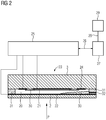
Figur 2- ein Blockschaltbild eines Druckmessumformers mit einer Prinzipdarstellung des Drucksensors.
- FIG. 1
- a sectional view of the part of a pressure transducer, which is often referred to as a measuring cell, and
- FIG. 2
- a block diagram of a pressure transducer with a schematic diagram of the pressure sensor.
In den beiden Figuren sind gleiche Teile mit gleichen Bezugszeichen versehen.In the two figures, the same parts are provided with the same reference numerals.
Zentrales Bauteil der im Wesentlichen rotationssymmetrischen Messzelle 1 ist ein scheibenförmiger Drucksensor 23, der eine Sensormembran 2 und einen Grundkörper 3 aufweist. Zwischen Sensormembran 2 und Grundkörper 3 wird eine Kavität 20 eingeschlossen, deren Aufbau später anhand
Zur Montage der Messzelle 1 wird zunächst der Dichtring 6 in die Nut eingelegt und ist dort aufgrund der schwalbenschwanzförmigen Nutform vor einem Herausfallen zuverlässig gesichert. Anschließend werden der Drucksensor 23 und der Distanzring 10 eingelegt. Zur Erzeugung der zur Lagerung des Drucksensors 23 erforderlichen axialen Einspannkraft wird anschließend das zweite Gehäuseteil 7, das gleichzeitig den rückseitigen Stützring darstellt, aufgesetzt und gegen das erste Gehäuseteil 4 gepresst. Dabei wird der Dichtring 6 derart zusammengedrückt, dass ein Spalt 12 zwischen der den Dichtring 6 umgebenden Fläche des ersten Gehäuseteils 4 und der dem Prozessmedium zugewandten Seite des Drucksensors 23 verbleibt. Die beiden zusammengepressten Gehäuseteile 4 und 7, welche rotationssymmetrisch sind, werden um ihre gemeinsame Achse gedreht und an ihrer kreisförmigen Stoßstelle durch eine Radialschweißung 13 miteinander verschweißt.For mounting the measuring
Übliche Drucksensoren 3 haben einen Durchmesser von ca. 32 mm. Die Dicke der Messmembran 2 beträgt je nach Druckmessbereich zwischen ca. 0,5 mm und ca. 2 mm. Die Kavität 20 hat eine Höhe von ca. 0,03 mm. Im Überlastfall wird die Messmembran 2 im mittleren Bereich um diesen Betrag verformt und legt sich an den Grundkörper 3 an. Bei stoßartiger Druckbelastung können im Bereich großer Materialspannung, insbesondere im Bereich der Fügestelle zwischen Messmembran 2 und Grundkörper 3, irreversible Überlastungen oder Beschädigungen auftreten. Tritt Prozessmedium aufgrund von Diffusion oder Undichtigkeiten an dem Dichtring 6 vorbei und gelangt zum Umfangsbereich des Drucksensors 23, kann dieses auch in die Kavität 20 gelangen und somit das Messergebnis des Druckmessumformers verfälschen, wenn beispielsweise eine Beschädigung in Form eines Spalts in der Glasfritte entstanden ist.
Anhand
In einem Druckmessmodus werden durch eine Ansteuer- und Auswerteeinrichtung 25 die jeweiligen Kapazitäten des Mess- und Referenzkondensators erfasst und in einen Messwert des Drucks P gewandelt, welcher über eine Schnittstelle 26 zu einer übergeordneten Steuerung 27 in einer nicht weiter dargestellten prozesstechnischen Anlage übertragen wird. Zur Vor-Ort-Anzeige kann der Messwert des Drucks zudem über eine Schnittstelle 28, beispielsweise ein W-LAN, an ein Servicegerät 29 ausgegeben werden, damit ein Servicemitarbeiter in der Anlage unmittelbar beim Feldgerät den Druckwert ablesen kann, ohne dass das Feldgerät selbst mit einem Anzeigefeld versehen sein muss.In a pressure measuring mode, the respective capacitances of the measuring and reference capacitor are detected by a control and
In zyklisch wiederkehrenden Zeitintervallen wechselt die Ansteuer- und Auswerteeinrichtung 25 in einen Diagnosemodus, in dem die Beschaltung eines CDC des Typs AD7746 von Analog Devices derart verändert wird, dass die Kapazität eines Diagnosekondensators, der durch die Messelektrode 21 und die Referenzelektrode 24, welche sich auf derselben Fläche an der Innenwand der Kavität 20 befinden, erfasst und zur Diagnose des Druckmessumformers ausgewertet wird. Bei der Messung der vergleichsweise kleinen Kapazität des Diagnosekondensators, die in der Größenordnung von einem Picofarad liegt, werden die Kapazitäten des Messkondensators sowie des Referenzkondensators, welche etwa um den Faktor 100 größer sind, als Schirmkapazitäten durch den CDC kompensiert. Im Diagnosemodus können bereits kleinere Veränderungen der Permittivität des in der Kavität 20 befindlichen Stoffgemischs, bei Relativdrucksensoren beispielsweise aufgrund einer Veränderung der relativen Luftfeuchtigkeit, erfasst und ihr Einfluss auf die Messung des Druckes P kompensiert werden. Dies kann beispielsweise anhand von zuvor empirisch ermittelten Kennlinien erfolgen, welche die Abhängigkeiten der Kapazitäten von Mess-und Referenzkondensator von der in der Kavität 20 herrschenden relativen Luftfeuchtigkeit beschreiben. Zur Überprüfung kann der Wert der in der Kavität 20 ermittelten relativen Luftfeuchtigkeit zudem auf der Anzeige des Servicegeräts 29 ausgegeben werden, damit ein Servicetechniker diesen mit einem Wert der relativen Feuchte vergleichen kann, den er mit einem gesonderten Sensor in der Umgebung erfasst hat.In cyclically recurring time intervals, the control and
Zur Erhöhung der Empfindlichkeit der Diagnosekapazität ist in der Kavität 20 ein kreisringförmiges Polymerdielektrikum 30 angeordnet, welches die im mittleren Bereich angeordnete Messelektrode 21 und die ringförmige, im Randbereich angeordnete Referenzelektrode 24 teilweise überdeckt. Als Polymerdielektrikum 30 eignet sich vorteilhaft eine Kaptonfolie, die sich in ihrer Kennlinie, welche die Abhängigkeit der dielektrischen Leitfähigkeit von der relativen Luftfeuchte beschreibt, durch eine besonders geringe Hysterese auszeichnet.To increase the sensitivity of the diagnostic capacity, an
Abweichend vom dargestellten Ausführungsbeispiel kann das Polymerdielektrikum zwischen oder unter den beiden Elektroden angeordnet werden. Für eine einfache Montage ist auch eine nachträgliche Einbringung des Polymerdielektrikums durch eine Öffnung im Grundkörper in eine für die Aufnahme des Polymerdielektrikums vorgesehene Ausnehmung des Grundkörpers vorteilhaft, wobei die Einbringung vorteilhaft erst erfolgt, nachdem der Grundkörper bereits unter Anwendung hoher Temperatur durch Verschmelzen der Glasfritte mit der Messmembran verbunden wurde.Deviating from the illustrated embodiment, the polymer dielectric can be arranged between or under the two electrodes. For a simple assembly, a subsequent introduction of the polymer dielectric through an opening in the base body in a recess provided for receiving the polymer dielectric recess of the base body advantageous, the introduction is advantageous only after the base body already using high temperature by fusing the glass frit with the Measuring membrane was connected.
Bereiche des Drucksensors 23, die bei an der Messmembran 2 anliegendem Druck P besonders hohen mechanischen Spannungen ausgesetzt sind, sind der Randbereich der Messmembran 2 sowie eine an der Fügestelle von Messmembran 2 und Grundkörper 3 befindliche sogenannte Glasfritte 31. Glaslote, die üblicherweise zur Herstellung der Glasfritte 31 verwendet werden, neigen bei thermischer und/oder mechanischer Belastung zur Rissbildung. Beispielsweise durch einen Riss 32 kann Prozessmedium 33, welches zuvor eine undichte Stelle der Dichtung 6 (
In Abhängigkeit der dielektrischen Leitfähigkeit des eindringenden Prozessmediums 33 kann abgeschätzt werden, zu welchem Zeitpunkt die fortschreitende Befüllung der Kavität 20 mit Prozessmedium 33 keine Messung des Drucks P mehr zulässt. Der Schätzwert für den verbleibenden Zeitraum bis zum erwarteten Auftreten des Funktionsausfalls kann in Abhängigkeit eines vorgegebenen Werts der Kapazität des Diagnosekondensators im Gutzustand, der bekannten dielektrischen Leitfähigkeit des in die Kavität 20 eindringenden Prozessmediums 33, der beiden vorgegebenen Schwellwerte und des Abstands der Zeitpunkte ihres Überschreitens ermittelt und ausgegeben werden. Durch Kenntnis der zur Verfügung stehenden Restlaufzeit des Druckmessumformers kann beispielsweise entschieden werden, ob der Druckmessumformer bereits beim nächsten Wartungszyklus oder erst beim übernächsten Wartungszyklus ausgetauscht werden muss. Wartungsmaßnahmen sind damit besser planbar. Erfolgt die Ausgabe des Warnsignals zur Anzeige eventuell erforderlicher Wartungsmaßnahmen auf dem Servicegerät 29, kann ein Servicetechniker vorteilhaft vor Ort die für eine Planung seiner Wartungsmaßnahmen erforderlichen Informationen erhalten.Depending on the dielectric conductivity of the penetrating
Claims (10)
- Method for operating a pressure transducer comprising a pressure sensor (23),
wherein the pressure sensor (23) has a flexible measurement membrane (2) and a base body (3), between which a cavity (20) is enclosed with a reference pressure,
wherein a deflection of the measurement membrane (2) is dependent on a media pressure (P), which is present on the media side at the measurement membrane (2), and on the reference pressure, wherein in order to capture a deflection of the measurement membrane (2) at least one first capacitor is provided which has two electrodes (21, 22) arranged in the central region of the measurement membrane (2) or of the base body (3) with a variable electrode spacing depending on the deflection, and
wherein at least one second capacitor is provided which has two electrodes (22, 24) arranged in the edge region of the measurement membrane (2) or of the base body (3), characterised in that
the capacitance of a diagnostics capacitor which is formed by one electrode (21) of the first capacitor and one electrode (24) of the second capacitor arranged on the same surface is determined and evaluated for the diagnosis of the pressure transducer. - Method according to claim 1, characterised in that in order to compensate for the influence of the permittivity of the medium contained in the cavity (20) the determined capacitance of the diagnostics capacitor is taken into consideration in the calculation of a measurement value for the media pressure (P) .
- Method according to claim 2, characterised in that a polymer dielectric (30) is arranged between the electrodes (21, 24) of the diagnostics capacitor in order to increase the sensitivity to humidity.
- Method according to one of the preceding claims, characterised in that the determined capacitance of the diagnostics capacitor is compared with a first predetermined threshold value and that in the event of the first threshold value being exceeded a warning signal is generated and output, which warning signal serves to indicate the existence of a critical state of the pressure sensor (23) as a precursor of a malfunction possibly following later.
- Method according to claim 4, characterised in that in the event of the first threshold value being exceeded the capacitance of the diagnostics capacitor is furthermore compared with a second predetermined threshold value and that in the event of the second threshold value also being exceeded an alarm signal is generated and output, which alarm signal serves to indicate an impending malfunction.
- Method according to claim 5, characterised in that an estimated value for a period of time until the occurrence of the malfunction is determined and output depending on a predefined value of the capacitance of the diagnostics capacitor in the go state, on a predefined dielectric conductivity of a medium (33) penetrating into the cavity (20), on the two threshold values and on the interval between the points in time when they are exceeded.
- Method according to one of claims 4 to 6, characterised in that the warning signal indicating possibly required maintenance measures is output on a service device (29).
- Pressure transducer comprising a pressure sensor (23), wherein the pressure sensor has a flexible measurement membrane (2) and a base body (3), between which a cavity (20) is enclosed with a reference pressure,
wherein a deflection of the measurement membrane (2) is dependent on a media pressure (P), which is present on the media side at the measurement membrane (2), and on the reference pressure,
wherein in order to capture a deflection of the measurement membrane (2) at least one first capacitor is provided which has two electrodes (21, 22) arranged in the central region of the measurement membrane (2) or of the base body (3) with a variable electrode spacing depending on the deflection, wherein at least one second capacitor is provided which has two electrodes (22, 24) arranged in the edge region of the measurement membrane (2) or of the base body (3), and
having a control and calculation unit (25) in order to capture the capacitance at least of the first capacitor and also to determine and output a measurement value for the media pressure (P) depending on the captured capacitance, characterised in that
the control and calculation unit (25) is moreover designed in order to determine the capacitance of a diagnostics capacitor, which is formed by one electrode (21) of the first capacitor and one electrode (24) of the second capacitor arranged on the same surface, and evaluate said capacitance for the diagnosis of the pressure transducer. - Computer program containing program code instructions which can be executed by a computer in order to implement the method according to one of claims 1 to 7 when the computer program is executed on a computer.
- Computer program product, in particular data medium or storage medium, containing a computer program according to claim 9 which can be executed by a computer.
Applications Claiming Priority (2)
| Application Number | Priority Date | Filing Date | Title |
|---|---|---|---|
| DE102014201529.4A DE102014201529A1 (en) | 2014-01-28 | 2014-01-28 | Method for operating a pressure transmitter and pressure transmitter |
| PCT/EP2014/063791 WO2015113654A1 (en) | 2014-01-28 | 2014-06-30 | Method for operating a pressure transducer and pressure transducer |
Publications (2)
| Publication Number | Publication Date |
|---|---|
| EP3100015A1 EP3100015A1 (en) | 2016-12-07 |
| EP3100015B1 true EP3100015B1 (en) | 2018-04-04 |
Family
ID=51022340
Family Applications (1)
| Application Number | Title | Priority Date | Filing Date |
|---|---|---|---|
| EP14733223.3A Active EP3100015B1 (en) | 2014-01-28 | 2014-06-30 | Method for operating a pressure transducer and pressure transducer |
Country Status (5)
| Country | Link |
|---|---|
| US (1) | US10048156B2 (en) |
| EP (1) | EP3100015B1 (en) |
| CN (1) | CN105829850B (en) |
| DE (1) | DE102014201529A1 (en) |
| WO (1) | WO2015113654A1 (en) |
Families Citing this family (12)
| Publication number | Priority date | Publication date | Assignee | Title |
|---|---|---|---|---|
| US10732056B2 (en) | 2016-06-09 | 2020-08-04 | Tri-Force Management Corporation | Force sensor |
| DE102017212875A1 (en) | 2017-07-26 | 2019-01-31 | Robert Bosch Gmbh | Micromechanical device and method for producing a micromechanical device |
| CN107562269B (en) * | 2017-08-28 | 2020-04-17 | 京东方科技集团股份有限公司 | Pressure touch structure and display device |
| DE102018114077B4 (en) | 2018-06-13 | 2020-02-13 | Danfoss A/S | Pressure sensor assembly |
| DE102018118645B3 (en) | 2018-08-01 | 2019-11-07 | Ifm Electronic Gmbh | Method for monitoring the function of a pressure measuring cell of a capacitive pressure sensor |
| DE102018118646B3 (en) * | 2018-08-01 | 2019-11-07 | Ifm Electronic Gmbh | Method for monitoring the function of a pressure measuring cell of a capacitive pressure sensor |
| US10942212B2 (en) | 2018-12-05 | 2021-03-09 | Psemi Corporation | System and method for testing radio frequency switches |
| US11054328B2 (en) | 2019-03-06 | 2021-07-06 | Psemi Corporation | Parasitic insensitive sampling in sensors |
| DE102019129264B4 (en) | 2019-10-30 | 2021-07-15 | Ifm Electronic Gmbh | Method for monitoring the function of a capacitive pressure measuring cell |
| CN114544065B (en) * | 2022-04-21 | 2022-07-15 | 季华实验室 | Capacitance film gauge, pressure measurement method, system, electronic device and storage medium |
| DE102022116708A1 (en) | 2022-07-05 | 2024-01-11 | Vega Grieshaber Kg | Measuring arrangement and method for operating a measuring arrangement |
| DE102022120883B3 (en) | 2022-08-18 | 2023-08-03 | Ifm Electronic Gmbh | Process for monitoring the function of a capacitive pressure measuring cell |
Family Cites Families (15)
| Publication number | Priority date | Publication date | Assignee | Title |
|---|---|---|---|---|
| JPS6151535A (en) * | 1984-08-22 | 1986-03-14 | Sharp Corp | Pressure sensor |
| FI93580C (en) * | 1993-10-08 | 1995-04-25 | Vaisala Oy | Method and apparatus for feedback of an asymmetric pressure differential sensor |
| CN1123764C (en) * | 2000-07-15 | 2003-10-08 | 山东省硅酸盐研究设计院 | Ceramic pressure sensor and differential pressure sensor |
| DE10235046A1 (en) * | 2002-07-31 | 2004-02-12 | Endress + Hauser Gmbh + Co. Kg | Capacitive pressure sensor |
| DE20219732U1 (en) | 2002-12-18 | 2003-03-06 | Dbt Autom Gmbh | Pressure transducers for measuring hydraulic pressures |
| US7026645B2 (en) | 2003-10-15 | 2006-04-11 | Delphi Technologies, Inc. | Leak detection method and micro-machined device assembly |
| KR20060094326A (en) | 2005-02-24 | 2006-08-29 | 삼성전자주식회사 | Apparatus for measuring pressure and method of inspecting operation state of the same |
| US7308830B2 (en) * | 2006-01-26 | 2007-12-18 | Rosemount Inc. | Pressure sensor fault detection |
| US8258450B1 (en) * | 2008-06-26 | 2012-09-04 | University Of South Florida | Physical and chemical integrated flow imaging device |
| DE102009002662B4 (en) * | 2009-04-27 | 2022-11-24 | Ifm Electronic Gmbh | Capacitive pressure sensor as a combination sensor for recording other measured variables |
| US8429978B2 (en) * | 2010-03-30 | 2013-04-30 | Rosemount Inc. | Resonant frequency based pressure sensor |
| DE102010062622A1 (en) | 2010-12-08 | 2012-06-14 | Ifm Electronic Gmbh | Method for self-monitoring of a ceramic pressure measuring cell of a capacitive pressure sensor and an evaluation circuit for carrying out the method |
| EP2520917A1 (en) * | 2011-05-04 | 2012-11-07 | Nxp B.V. | MEMS Capacitive Pressure Sensor, Operating Method and Manufacturing Method |
| DE102011078557A1 (en) | 2011-07-01 | 2013-01-03 | Endress + Hauser Gmbh + Co. Kg | Method for operating an absolute or relative pressure sensor with a capacitive transducer |
| CN102928133B (en) | 2012-10-12 | 2015-03-18 | 深圳市安培盛科技有限公司 | Ceramic capacitive pressure sensor |
-
2014
- 2014-01-28 DE DE102014201529.4A patent/DE102014201529A1/en not_active Withdrawn
- 2014-06-30 US US15/113,805 patent/US10048156B2/en active Active
- 2014-06-30 WO PCT/EP2014/063791 patent/WO2015113654A1/en active Application Filing
- 2014-06-30 CN CN201480068654.6A patent/CN105829850B/en active Active
- 2014-06-30 EP EP14733223.3A patent/EP3100015B1/en active Active
Also Published As
| Publication number | Publication date |
|---|---|
| CN105829850A (en) | 2016-08-03 |
| CN105829850B (en) | 2018-09-25 |
| US20160341623A1 (en) | 2016-11-24 |
| WO2015113654A1 (en) | 2015-08-06 |
| DE102014201529A1 (en) | 2015-07-30 |
| US10048156B2 (en) | 2018-08-14 |
| EP3100015A1 (en) | 2016-12-07 |
Similar Documents
| Publication | Publication Date | Title |
|---|---|---|
| EP3100015B1 (en) | Method for operating a pressure transducer and pressure transducer | |
| DE102004060647B4 (en) | Remote process seal with improved stability in demanding applications | |
| EP1664715B1 (en) | Pressure transducer provided with a piezoelectric element for the detection of errors in separation membranes | |
| EP2062021A1 (en) | Method and apparatus for the diagnosis of losses of liquid in pressure measuring sensors filled with pressure-transmitting liquids | |
| DE202004021565U1 (en) | Device for condition monitoring of a pressure measuring device | |
| DE102014118616A1 (en) | pressure transducers | |
| EP2870354B1 (en) | Monitored component connection, wind power system, method for monitoring a component connection for inadvertent loosening of the component connection in the connected state | |
| EP3084382A1 (en) | Leak-monitoring system for space-enclosing objects and coupling regions lying therebetween, as well as an associated method | |
| EP1425563B1 (en) | Pressure measuring apparatus | |
| EP1275951B1 (en) | Pressure sensor and procedure for monitoring its functioning | |
| WO2003002969A1 (en) | Pressure transmitting device with forecasting corrosion monitoring | |
| WO2007031516A1 (en) | Pressure measurement transducer | |
| DE102018209877A1 (en) | Electrochemical energy storage device, system and method for monitoring an electrochemical energy storage device and vehicle | |
| DE102011111558B4 (en) | Dry transducer | |
| WO2012098136A1 (en) | Pressure measurement transducer | |
| EP3767266B1 (en) | Pressure medium system or pressure transducer with integrated self-test | |
| EP3237866B1 (en) | Pressure transducer and method for operating same | |
| DE102011005705A1 (en) | Capacitive pressure sensor | |
| DE102009024576A1 (en) | Differential Pressure Sensor | |
| DE102019209353B4 (en) | Diaphragm seal system with monitoring function | |
| WO2012028428A2 (en) | Pressure measurement transducer | |
| EP3329236B1 (en) | Pressure sensor and method for monitoring a pressure sensor | |
| DE102013107535B4 (en) | Diaphragm seal system with a diaphragm seal and method for detecting a diaphragm rupture | |
| DE102020116702A1 (en) | Pressure gauge | |
| DE102020208326B4 (en) | Condition monitoring of a measuring device |
Legal Events
| Date | Code | Title | Description |
|---|---|---|---|
| PUAI | Public reference made under article 153(3) epc to a published international application that has entered the european phase |
Free format text: ORIGINAL CODE: 0009012 |
|
| 17P | Request for examination filed |
Effective date: 20160630 |
|
| AK | Designated contracting states |
Kind code of ref document: A1 Designated state(s): AL AT BE BG CH CY CZ DE DK EE ES FI FR GB GR HR HU IE IS IT LI LT LU LV MC MK MT NL NO PL PT RO RS SE SI SK SM TR |
|
| AX | Request for extension of the european patent |
Extension state: BA ME |
|
| DAX | Request for extension of the european patent (deleted) | ||
| RAP1 | Party data changed (applicant data changed or rights of an application transferred) |
Owner name: SIEMENS AKTIENGESELLSCHAFT |
|
| GRAP | Despatch of communication of intention to grant a patent |
Free format text: ORIGINAL CODE: EPIDOSNIGR1 |
|
| INTG | Intention to grant announced |
Effective date: 20171009 |
|
| GRAS | Grant fee paid |
Free format text: ORIGINAL CODE: EPIDOSNIGR3 |
|
| GRAA | (expected) grant |
Free format text: ORIGINAL CODE: 0009210 |
|
| AK | Designated contracting states |
Kind code of ref document: B1 Designated state(s): AL AT BE BG CH CY CZ DE DK EE ES FI FR GB GR HR HU IE IS IT LI LT LU LV MC MK MT NL NO PL PT RO RS SE SI SK SM TR |
|
| REG | Reference to a national code |
Ref country code: GB Ref legal event code: FG4D Free format text: NOT ENGLISH |
|
| REG | Reference to a national code |
Ref country code: CH Ref legal event code: EP |
|
| REG | Reference to a national code |
Ref country code: AT Ref legal event code: REF Ref document number: 986102 Country of ref document: AT Kind code of ref document: T Effective date: 20180415 |
|
| REG | Reference to a national code |
Ref country code: IE Ref legal event code: FG4D Free format text: LANGUAGE OF EP DOCUMENT: GERMAN |
|
| REG | Reference to a national code |
Ref country code: DE Ref legal event code: R096 Ref document number: 502014007846 Country of ref document: DE |
|
| REG | Reference to a national code |
Ref country code: NL Ref legal event code: MP Effective date: 20180404 |
|
| REG | Reference to a national code |
Ref country code: LT Ref legal event code: MG4D |
|
| PG25 | Lapsed in a contracting state [announced via postgrant information from national office to epo] |
Ref country code: NL Free format text: LAPSE BECAUSE OF FAILURE TO SUBMIT A TRANSLATION OF THE DESCRIPTION OR TO PAY THE FEE WITHIN THE PRESCRIBED TIME-LIMIT Effective date: 20180404 |
|
| PG25 | Lapsed in a contracting state [announced via postgrant information from national office to epo] |
Ref country code: BG Free format text: LAPSE BECAUSE OF FAILURE TO SUBMIT A TRANSLATION OF THE DESCRIPTION OR TO PAY THE FEE WITHIN THE PRESCRIBED TIME-LIMIT Effective date: 20180704 Ref country code: SE Free format text: LAPSE BECAUSE OF FAILURE TO SUBMIT A TRANSLATION OF THE DESCRIPTION OR TO PAY THE FEE WITHIN THE PRESCRIBED TIME-LIMIT Effective date: 20180404 Ref country code: AL Free format text: LAPSE BECAUSE OF FAILURE TO SUBMIT A TRANSLATION OF THE DESCRIPTION OR TO PAY THE FEE WITHIN THE PRESCRIBED TIME-LIMIT Effective date: 20180404 Ref country code: FI Free format text: LAPSE BECAUSE OF FAILURE TO SUBMIT A TRANSLATION OF THE DESCRIPTION OR TO PAY THE FEE WITHIN THE PRESCRIBED TIME-LIMIT Effective date: 20180404 Ref country code: PL Free format text: LAPSE BECAUSE OF FAILURE TO SUBMIT A TRANSLATION OF THE DESCRIPTION OR TO PAY THE FEE WITHIN THE PRESCRIBED TIME-LIMIT Effective date: 20180404 Ref country code: NO Free format text: LAPSE BECAUSE OF FAILURE TO SUBMIT A TRANSLATION OF THE DESCRIPTION OR TO PAY THE FEE WITHIN THE PRESCRIBED TIME-LIMIT Effective date: 20180704 Ref country code: LT Free format text: LAPSE BECAUSE OF FAILURE TO SUBMIT A TRANSLATION OF THE DESCRIPTION OR TO PAY THE FEE WITHIN THE PRESCRIBED TIME-LIMIT Effective date: 20180404 Ref country code: ES Free format text: LAPSE BECAUSE OF FAILURE TO SUBMIT A TRANSLATION OF THE DESCRIPTION OR TO PAY THE FEE WITHIN THE PRESCRIBED TIME-LIMIT Effective date: 20180404 |
|
| PG25 | Lapsed in a contracting state [announced via postgrant information from national office to epo] |
Ref country code: HR Free format text: LAPSE BECAUSE OF FAILURE TO SUBMIT A TRANSLATION OF THE DESCRIPTION OR TO PAY THE FEE WITHIN THE PRESCRIBED TIME-LIMIT Effective date: 20180404 Ref country code: GR Free format text: LAPSE BECAUSE OF FAILURE TO SUBMIT A TRANSLATION OF THE DESCRIPTION OR TO PAY THE FEE WITHIN THE PRESCRIBED TIME-LIMIT Effective date: 20180705 Ref country code: LV Free format text: LAPSE BECAUSE OF FAILURE TO SUBMIT A TRANSLATION OF THE DESCRIPTION OR TO PAY THE FEE WITHIN THE PRESCRIBED TIME-LIMIT Effective date: 20180404 Ref country code: RS Free format text: LAPSE BECAUSE OF FAILURE TO SUBMIT A TRANSLATION OF THE DESCRIPTION OR TO PAY THE FEE WITHIN THE PRESCRIBED TIME-LIMIT Effective date: 20180404 |
|
| PG25 | Lapsed in a contracting state [announced via postgrant information from national office to epo] |
Ref country code: PT Free format text: LAPSE BECAUSE OF FAILURE TO SUBMIT A TRANSLATION OF THE DESCRIPTION OR TO PAY THE FEE WITHIN THE PRESCRIBED TIME-LIMIT Effective date: 20180806 |
|
| REG | Reference to a national code |
Ref country code: DE Ref legal event code: R097 Ref document number: 502014007846 Country of ref document: DE |
|
| PG25 | Lapsed in a contracting state [announced via postgrant information from national office to epo] |
Ref country code: EE Free format text: LAPSE BECAUSE OF FAILURE TO SUBMIT A TRANSLATION OF THE DESCRIPTION OR TO PAY THE FEE WITHIN THE PRESCRIBED TIME-LIMIT Effective date: 20180404 Ref country code: CZ Free format text: LAPSE BECAUSE OF FAILURE TO SUBMIT A TRANSLATION OF THE DESCRIPTION OR TO PAY THE FEE WITHIN THE PRESCRIBED TIME-LIMIT Effective date: 20180404 Ref country code: RO Free format text: LAPSE BECAUSE OF FAILURE TO SUBMIT A TRANSLATION OF THE DESCRIPTION OR TO PAY THE FEE WITHIN THE PRESCRIBED TIME-LIMIT Effective date: 20180404 Ref country code: DK Free format text: LAPSE BECAUSE OF FAILURE TO SUBMIT A TRANSLATION OF THE DESCRIPTION OR TO PAY THE FEE WITHIN THE PRESCRIBED TIME-LIMIT Effective date: 20180404 Ref country code: SK Free format text: LAPSE BECAUSE OF FAILURE TO SUBMIT A TRANSLATION OF THE DESCRIPTION OR TO PAY THE FEE WITHIN THE PRESCRIBED TIME-LIMIT Effective date: 20180404 |
|
| REG | Reference to a national code |
Ref country code: CH Ref legal event code: PL |
|
| PLBE | No opposition filed within time limit |
Free format text: ORIGINAL CODE: 0009261 |
|
| STAA | Information on the status of an ep patent application or granted ep patent |
Free format text: STATUS: NO OPPOSITION FILED WITHIN TIME LIMIT |
|
| PG25 | Lapsed in a contracting state [announced via postgrant information from national office to epo] |
Ref country code: IT Free format text: LAPSE BECAUSE OF FAILURE TO SUBMIT A TRANSLATION OF THE DESCRIPTION OR TO PAY THE FEE WITHIN THE PRESCRIBED TIME-LIMIT Effective date: 20180404 Ref country code: SM Free format text: LAPSE BECAUSE OF FAILURE TO SUBMIT A TRANSLATION OF THE DESCRIPTION OR TO PAY THE FEE WITHIN THE PRESCRIBED TIME-LIMIT Effective date: 20180404 |
|
| REG | Reference to a national code |
Ref country code: BE Ref legal event code: MM Effective date: 20180630 |
|
| 26N | No opposition filed |
Effective date: 20190107 |
|
| GBPC | Gb: european patent ceased through non-payment of renewal fee |
Effective date: 20180704 |
|
| PG25 | Lapsed in a contracting state [announced via postgrant information from national office to epo] |
Ref country code: MC Free format text: LAPSE BECAUSE OF FAILURE TO SUBMIT A TRANSLATION OF THE DESCRIPTION OR TO PAY THE FEE WITHIN THE PRESCRIBED TIME-LIMIT Effective date: 20180404 Ref country code: LU Free format text: LAPSE BECAUSE OF NON-PAYMENT OF DUE FEES Effective date: 20180630 |
|
| REG | Reference to a national code |
Ref country code: IE Ref legal event code: MM4A |
|
| PG25 | Lapsed in a contracting state [announced via postgrant information from national office to epo] |
Ref country code: LI Free format text: LAPSE BECAUSE OF NON-PAYMENT OF DUE FEES Effective date: 20180630 Ref country code: GB Free format text: LAPSE BECAUSE OF NON-PAYMENT OF DUE FEES Effective date: 20180704 Ref country code: CH Free format text: LAPSE BECAUSE OF NON-PAYMENT OF DUE FEES Effective date: 20180630 Ref country code: FR Free format text: LAPSE BECAUSE OF NON-PAYMENT OF DUE FEES Effective date: 20180630 Ref country code: IE Free format text: LAPSE BECAUSE OF NON-PAYMENT OF DUE FEES Effective date: 20180630 |
|
| PG25 | Lapsed in a contracting state [announced via postgrant information from national office to epo] |
Ref country code: BE Free format text: LAPSE BECAUSE OF NON-PAYMENT OF DUE FEES Effective date: 20180630 Ref country code: SI Free format text: LAPSE BECAUSE OF FAILURE TO SUBMIT A TRANSLATION OF THE DESCRIPTION OR TO PAY THE FEE WITHIN THE PRESCRIBED TIME-LIMIT Effective date: 20180404 |
|
| PG25 | Lapsed in a contracting state [announced via postgrant information from national office to epo] |
Ref country code: MT Free format text: LAPSE BECAUSE OF FAILURE TO SUBMIT A TRANSLATION OF THE DESCRIPTION OR TO PAY THE FEE WITHIN THE PRESCRIBED TIME-LIMIT Effective date: 20180404 |
|
| PG25 | Lapsed in a contracting state [announced via postgrant information from national office to epo] |
Ref country code: TR Free format text: LAPSE BECAUSE OF FAILURE TO SUBMIT A TRANSLATION OF THE DESCRIPTION OR TO PAY THE FEE WITHIN THE PRESCRIBED TIME-LIMIT Effective date: 20180404 |
|
| PG25 | Lapsed in a contracting state [announced via postgrant information from national office to epo] |
Ref country code: HU Free format text: LAPSE BECAUSE OF FAILURE TO SUBMIT A TRANSLATION OF THE DESCRIPTION OR TO PAY THE FEE WITHIN THE PRESCRIBED TIME-LIMIT; INVALID AB INITIO Effective date: 20140630 Ref country code: MK Free format text: LAPSE BECAUSE OF NON-PAYMENT OF DUE FEES Effective date: 20180404 Ref country code: CY Free format text: LAPSE BECAUSE OF FAILURE TO SUBMIT A TRANSLATION OF THE DESCRIPTION OR TO PAY THE FEE WITHIN THE PRESCRIBED TIME-LIMIT Effective date: 20180404 |
|
| PG25 | Lapsed in a contracting state [announced via postgrant information from national office to epo] |
Ref country code: IS Free format text: LAPSE BECAUSE OF FAILURE TO SUBMIT A TRANSLATION OF THE DESCRIPTION OR TO PAY THE FEE WITHIN THE PRESCRIBED TIME-LIMIT Effective date: 20180804 |
|
| REG | Reference to a national code |
Ref country code: AT Ref legal event code: MM01 Ref document number: 986102 Country of ref document: AT Kind code of ref document: T Effective date: 20190630 |
|
| PG25 | Lapsed in a contracting state [announced via postgrant information from national office to epo] |
Ref country code: AT Free format text: LAPSE BECAUSE OF NON-PAYMENT OF DUE FEES Effective date: 20190630 |
|
| PGFP | Annual fee paid to national office [announced via postgrant information from national office to epo] |
Ref country code: DE Payment date: 20230818 Year of fee payment: 10 |