EP3329236B1 - Pressure sensor and method for monitoring a pressure sensor - Google Patents
Pressure sensor and method for monitoring a pressure sensor Download PDFInfo
- Publication number
- EP3329236B1 EP3329236B1 EP16730853.5A EP16730853A EP3329236B1 EP 3329236 B1 EP3329236 B1 EP 3329236B1 EP 16730853 A EP16730853 A EP 16730853A EP 3329236 B1 EP3329236 B1 EP 3329236B1
- Authority
- EP
- European Patent Office
- Prior art keywords
- pressure sensor
- electrical signal
- change
- malfunction
- pressure
- Prior art date
- Legal status (The legal status is an assumption and is not a legal conclusion. Google has not performed a legal analysis and makes no representation as to the accuracy of the status listed.)
- Active
Links
- 238000000034 method Methods 0.000 title claims description 18
- 238000012544 monitoring process Methods 0.000 title claims description 6
- 230000003287 optical effect Effects 0.000 claims description 31
- 239000012528 membrane Substances 0.000 claims description 30
- 230000007257 malfunction Effects 0.000 claims description 24
- 230000005284 excitation Effects 0.000 claims description 23
- 239000004065 semiconductor Substances 0.000 claims description 9
- 238000011156 evaluation Methods 0.000 claims description 8
- 239000000463 material Substances 0.000 claims description 6
- 230000001419 dependent effect Effects 0.000 claims description 5
- 238000001514 detection method Methods 0.000 claims description 2
- 238000005259 measurement Methods 0.000 description 7
- 230000000694 effects Effects 0.000 description 5
- XUIMIQQOPSSXEZ-UHFFFAOYSA-N Silicon Chemical compound [Si] XUIMIQQOPSSXEZ-UHFFFAOYSA-N 0.000 description 4
- 229910052710 silicon Inorganic materials 0.000 description 4
- 239000010703 silicon Substances 0.000 description 4
- 238000012935 Averaging Methods 0.000 description 3
- 238000009530 blood pressure measurement Methods 0.000 description 2
- 238000010586 diagram Methods 0.000 description 2
- 230000032683 aging Effects 0.000 description 1
- 230000015572 biosynthetic process Effects 0.000 description 1
- 238000003745 diagnosis Methods 0.000 description 1
- 238000006073 displacement reaction Methods 0.000 description 1
- 238000005530 etching Methods 0.000 description 1
- 230000002093 peripheral effect Effects 0.000 description 1
- 210000002023 somite Anatomy 0.000 description 1
Images
Classifications
-
- G—PHYSICS
- G01—MEASURING; TESTING
- G01L—MEASURING FORCE, STRESS, TORQUE, WORK, MECHANICAL POWER, MECHANICAL EFFICIENCY, OR FLUID PRESSURE
- G01L9/00—Measuring steady of quasi-steady pressure of fluid or fluent solid material by electric or magnetic pressure-sensitive elements; Transmitting or indicating the displacement of mechanical pressure-sensitive elements, used to measure the steady or quasi-steady pressure of a fluid or fluent solid material, by electric or magnetic means
- G01L9/0041—Transmitting or indicating the displacement of flexible diaphragms
- G01L9/0076—Transmitting or indicating the displacement of flexible diaphragms using photoelectric means
-
- G—PHYSICS
- G01—MEASURING; TESTING
- G01L—MEASURING FORCE, STRESS, TORQUE, WORK, MECHANICAL POWER, MECHANICAL EFFICIENCY, OR FLUID PRESSURE
- G01L9/00—Measuring steady of quasi-steady pressure of fluid or fluent solid material by electric or magnetic pressure-sensitive elements; Transmitting or indicating the displacement of mechanical pressure-sensitive elements, used to measure the steady or quasi-steady pressure of a fluid or fluent solid material, by electric or magnetic means
- G01L9/0001—Transmitting or indicating the displacement of elastically deformable gauges by electric, electro-mechanical, magnetic or electro-magnetic means
- G01L9/0007—Transmitting or indicating the displacement of elastically deformable gauges by electric, electro-mechanical, magnetic or electro-magnetic means using photoelectric means
-
- G—PHYSICS
- G01—MEASURING; TESTING
- G01L—MEASURING FORCE, STRESS, TORQUE, WORK, MECHANICAL POWER, MECHANICAL EFFICIENCY, OR FLUID PRESSURE
- G01L9/00—Measuring steady of quasi-steady pressure of fluid or fluent solid material by electric or magnetic pressure-sensitive elements; Transmitting or indicating the displacement of mechanical pressure-sensitive elements, used to measure the steady or quasi-steady pressure of a fluid or fluent solid material, by electric or magnetic means
- G01L9/0001—Transmitting or indicating the displacement of elastically deformable gauges by electric, electro-mechanical, magnetic or electro-magnetic means
- G01L9/0008—Transmitting or indicating the displacement of elastically deformable gauges by electric, electro-mechanical, magnetic or electro-magnetic means using vibrations
- G01L9/0019—Transmitting or indicating the displacement of elastically deformable gauges by electric, electro-mechanical, magnetic or electro-magnetic means using vibrations of a semiconductive element
- G01L9/002—Optical excitation or measuring
-
- G—PHYSICS
- G01—MEASURING; TESTING
- G01L—MEASURING FORCE, STRESS, TORQUE, WORK, MECHANICAL POWER, MECHANICAL EFFICIENCY, OR FLUID PRESSURE
- G01L9/00—Measuring steady of quasi-steady pressure of fluid or fluent solid material by electric or magnetic pressure-sensitive elements; Transmitting or indicating the displacement of mechanical pressure-sensitive elements, used to measure the steady or quasi-steady pressure of a fluid or fluent solid material, by electric or magnetic means
- G01L9/0041—Transmitting or indicating the displacement of flexible diaphragms
- G01L9/0051—Transmitting or indicating the displacement of flexible diaphragms using variations in ohmic resistance
- G01L9/0052—Transmitting or indicating the displacement of flexible diaphragms using variations in ohmic resistance of piezoresistive elements
- G01L9/0054—Transmitting or indicating the displacement of flexible diaphragms using variations in ohmic resistance of piezoresistive elements integral with a semiconducting diaphragm
Definitions
- the invention relates to a pressure sensor for determining a measured pressure variable and a method for monitoring such a pressure sensor.
- Pressure sensors are used to record pressures and are often used in industrial measurement technology, e.g. for level measurement or flow measurement. Depending on the area of application, different types of pressure sensors are used.
- a pressure sensor can be designed, for example, as an absolute pressure sensor, as a relative pressure sensor or as a differential pressure sensor. In principle, however, all pressure sensors have the same structure and typically include a housing in which a pressure sensor element is arranged.
- semiconductor pressure sensor elements for example pressure sensor elements based on silicon, are often used. The semiconductor pressure sensor elements have a measuring diaphragm which typically has four resistance elements integrated in its edge area.
- the measuring membrane is subjected to a first pressure on its first side and a second pressure to its second side, so that the two pressures cause the measuring membrane to deflect.
- the pressure-dependent deflection of the measuring membrane is recorded and evaluated via the integrated resistance elements so that a pressure variable can be output.
- the measuring membrane is subjected to the corresponding two pressures.
- the pressure sensor is designed as an absolute pressure sensor, one of the two sides of the measuring membrane is exposed to a vacuum and the other side of the measuring membrane is supplied with a media pressure to be measured.
- the absolute pressure sensor thus measures the absolute pressure, i.e. the medium pressure to be measured in comparison to the vacuum as the reference pressure.
- the pressure sensor is designed as a relative pressure sensor, one of the two sides of the measuring membrane is exposed to atmospheric air pressure as a reference pressure and a media pressure to be measured is supplied to the other side of the measuring membrane.
- the relative pressure sensor thus measures a relative pressure, ie the media pressure to be measured in comparison to the atmospheric air pressure.
- the pressure sensor is designed as a differential pressure sensor, a first media pressure to be measured is fed to one of the two sides of the measuring membrane and a second media pressure to be measured is fed to the other side of the measuring membrane.
- the differential pressure sensor thus measures a differential pressure, i.e. the difference between the two medium pressures.
- the U.S. 3,714,829 A discloses a pressure measurement system having a light source and a pressure sensitive membrane illuminated by the light source and such is designed to reflect the light as a function of the detected pressure.
- the GB 2 039 414 A discloses a sensor block arranged in a housing, which comprises a semiconductor diaphragm and a peripheral support which is glued to the inside of the housing.
- U.S. 5,101,664A discloses a micromachined silicon pressure transducer with a vibrating bridge formed from the same silicon plate as the pressure sensitive diaphragm.
- the GB 2 185 106A discloses an optically driven vibration sensor.
- the U.S. 4,631,401A discloses an optical displacement sensor including first and second optical circuits.
- the invention is based on the object of demonstrating a solution that enables a pressure sensor to be monitored or checked.
- the object is achieved according to the invention by a pressure sensor and a method for monitoring a pressure sensor.
- the effect referred to as photoconduction is used to enable diagnosis or monitoring of a pressure sensor.
- Photoconduction is understood as meaning an effect associated with the internal photoelectric effect, in which the increase in the electrical conductivity of semiconductor materials occurs due to the formation of unbound electron-hole pairs during irradiation.
- the pressure sensor element which is a semiconductor material and a measuring membrane with at least one integrated resistance element
- the respective measurable electrical resistance of the resistance element and thus also an electrical signal for example a bridge voltage signal
- This change can be used to determine with a high degree of probability whether there is a malfunction in the pressure sensor.
- Typical malfunctions that can be determined in this way are, for example, a drift in the resistance elements and/or a fracture or tear in the measuring membrane.
- An advantageous embodiment of the pressure sensor according to the invention provides that in the event that there is a malfunction, the pressure sensor emits a warning signal.
- An advantageous embodiment of the pressure sensor according to the invention provides that the optical excitation includes a number of individual optical pulses.
- An advantageous embodiment of the pressure sensor according to the invention provides that the optical excitation of the pressure sensor element, in particular the integrated resistance element, takes place after a defined or fixed period of time.
- An advantageous embodiment of the pressure sensor according to the invention provides that the measuring membrane has further integrated resistance elements and a lamp is provided for each further resistance element.
- An advantageous embodiment of the pressure sensor according to the invention provides that the lighting means is a light-emitting diode.
- the object is achieved by a method for monitoring a pressure sensor according to claim 7.
- An advantageous embodiment provides that, in order to determine whether a malfunction of the pressure sensor is due to the detected change in the electrical signal is present, the detected change in the electrical signal is compared with an expected value and in the event that the detected change in the electrical signal is outside a tolerance range around the expected value, the malfunction of the pressure sensor is determined.
- a further advantageous embodiment provides that a number of individual optical pulses are used for the optical excitation and a number of individual electrical signal values are recorded to record the change in the electrical signal.
- the embodiment provides that the change in the electrical signal is determined by averaging the detected multiple electrical individual signal values.
- a further advantageous embodiment provides that a warning signal is output in the event that there is a malfunction in the pressure sensor.
- a further advantageous embodiment provides that the optical excitation is carried out at regular intervals during the measuring operation.
- a further advantageous embodiment provides that a time profile of the change in the electrical signal is recorded and the malfunction of the pressure sensor is determined on the basis of the time profile.
- a further advantageous embodiment provides that the pressure sensor element has a plurality of integrated resistance elements and a selective optical excitation of each of the integrated resistance elements is carried out, and a change in a respective electrical signal is detected for each of the integrated resistance elements and it is determined whether on the basis of the respectively detected change in the electrical signal there is a malfunction in the pressure sensor.
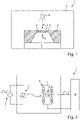
- FIG 1 shows a schematic representation of the pressure sensor 1 according to the invention. This comprises a housing 2, a pressure sensor element 3 arranged in the housing 2 and a lighting means 4 also arranged in the housing.
- the pressure sensor element 3 introduced into the housing 2 has a semiconductor material, preferably silicon.
- a measuring membrane 5 is introduced into the pressure sensor element 3, for example by means of an etching process.
- measuring diaphragm 5 is subjected to a first pressure p 1 , e.g. atmospheric pressure, on a first side, and a second pressure p 2 , e.g measuring media pressure, supplied.
- the measuring diaphragm again includes four resistance elements 6, which are generated, for example, by doping the semiconductor material.
- the resistance elements 6 integrated into the measuring membrane 5 in this way are typically arranged in the edge region of the measuring membrane 5 in order to detect the pressure-dependent deflection of the measuring membrane 5 in the form of a change in resistance. Based on the changes in resistance of the resistance elements 6, the pressure sensor 1 can determine or output a measured pressure variable.
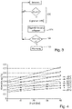
- FIG. 2 shows a schematic block diagram of the pressure sensor 1 according to the invention, which in addition to the light source 4 with a corresponding light source drive unit 7 and the resistance elements 6 also includes a control/evaluation unit 8 .
- the resistance elements 6 are connected to form a Wheatstone bridge 9 and the control/evaluation unit 8 is typically used to record an electrical signal 10 representing the resistance values, for example the bridge voltage signal U B .
- the control/evaluation unit 8 uses the recorded electrical signal 10, in the illustrated case the bridge voltage U B , to determine a measured pressure variable.
- FIG. 4 shows an experimentally determined measurement curve.
- the optical excitation was carried out by a large number of individual optical pulses at the appropriate pressures and temperatures.
- the change or deviation in the electrical signal was recorded by averaging the recorded multiple individual signal values, the change or deviation being the difference between the electrical signal with optical excitation and the electrical signal without optical excitation.
- the detected electrical signal 10 shows a change which is due to the optical excitation. Also evident from 4 is that the electrical signal 10 is dependent on temperature and pressure, which may still have to be compensated for before a malfunction of the pressure sensor 1 can be determined. If, despite a possible temperature and pressure compensation, there is a change in the electrical signal that goes beyond the tolerance range, it can be assumed with high probability that there is a malfunction, for example a drift of the resistance elements 6 and/or a membrane rupture or membrane tear.
Description
Die Erfindung bezieht sich auf einen Drucksensor zur Bestimmung einer Druckmessgröße sowie ein Verfahren zum Überwachen eines solchen Drucksensors.The invention relates to a pressure sensor for determining a measured pressure variable and a method for monitoring such a pressure sensor.
Drucksensoren dienen zur Erfassung von Drücken und werden gerne in der industriellen Messtechnik, bspw. zur Füllstandsmessung oder zur Durchflussmessung verwendet. Dabei kommen je nach Einsatzgebiet unterschiedliche Ausprägungen von Drucksensoren zum Einsatz. So kann ein Drucksensor bspw. als Absolutdrucksensor, als Relativdrucksensor oder auch als Differenzdrucksensor ausgebildet sein. Vom Prinzip her sind jedoch alle Drucksensoren gleich aufgebaut und umfassen typischerweise ein Gehäuse in dem ein Drucksensorelement angeordnet ist. In der Druckmesstechnik werden gerne Halbleiter-Drucksensorelemente, bspw. auf Silizium basierende Drucksensorelemente, eingesetzt. Die Halbleiter-Drucksensorelemente weisen dabei eine Messmembran auf, welche in ihrem Randbereich typischerweise vier Widerstandselemente integriert hat. Die Messmembran wird auf ihrer ersten Seite mit einem ersten Druck und auf ihrer zweiten Seite mit einem zweiten Druck beaufschlagt, sodass die beiden Drücke eine Auslenkung der Messmembran hervorrufen. Die druckabhängige Auslenkung der Messmembran wird über die integrierten Widerstandselemente erfasst und ausgewertet, sodass eine Druckmessgröße ausgegeben werden kann. In Abhängigkeit davon, ob es sich um einen Relativdrucksensor, einen Absolutdrucksensor oder einen Differenzdrucksensor handelt, wird die Messmembran mit den entsprechenden beiden Drücken beaufschlagt.Pressure sensors are used to record pressures and are often used in industrial measurement technology, e.g. for level measurement or flow measurement. Depending on the area of application, different types of pressure sensors are used. A pressure sensor can be designed, for example, as an absolute pressure sensor, as a relative pressure sensor or as a differential pressure sensor. In principle, however, all pressure sensors have the same structure and typically include a housing in which a pressure sensor element is arranged. In pressure measurement technology, semiconductor pressure sensor elements, for example pressure sensor elements based on silicon, are often used. The semiconductor pressure sensor elements have a measuring diaphragm which typically has four resistance elements integrated in its edge area. The measuring membrane is subjected to a first pressure on its first side and a second pressure to its second side, so that the two pressures cause the measuring membrane to deflect. The pressure-dependent deflection of the measuring membrane is recorded and evaluated via the integrated resistance elements so that a pressure variable can be output. Depending on whether it is a relative pressure sensor, an absolute pressure sensor or a differential pressure sensor, the measuring membrane is subjected to the corresponding two pressures.
In dem Fall, dass der Drucksensor als Absolutdrucksensor ausgebildet ist, wird eine der beiden Seiten der Messmembran einem Vakuum ausgesetzt und der anderen Seite der Messmembran wird ein zu messender Mediendruck zugeführt. Der Absolutdrucksensor misst somit den Absolutdruck, also den zu messenden Mediendruck im Vergleich zu dem Vakuum als Referenzdruck.If the pressure sensor is designed as an absolute pressure sensor, one of the two sides of the measuring membrane is exposed to a vacuum and the other side of the measuring membrane is supplied with a media pressure to be measured. Of the The absolute pressure sensor thus measures the absolute pressure, i.e. the medium pressure to be measured in comparison to the vacuum as the reference pressure.
In dem Fall, dass der Drucksensor als Relativdrucksensor ausgebildet ist, wird eine der beiden Seiten der Messmembran einem atmosphärischen Luftdruck als Referenzdruck ausgesetzt und der anderen Seite der Messmembran wird ein zu messender Mediendruck zugeführt. Der Relativdrucksensor misst somit einen Relativdruck, also den zu messenden Mediendruck im Vergleich zu dem atmosphärischen Luftdruck.If the pressure sensor is designed as a relative pressure sensor, one of the two sides of the measuring membrane is exposed to atmospheric air pressure as a reference pressure and a media pressure to be measured is supplied to the other side of the measuring membrane. The relative pressure sensor thus measures a relative pressure, ie the media pressure to be measured in comparison to the atmospheric air pressure.
In dem Fall, dass der Drucksensor als Differenzdrucksensor ausgebildet ist, wird einer der beiden Seiten der Messmembran ein erster zu messender Mediendruck und der anderen Seite der Messmembran ein zweiter zu messender Mediendruck zugeführt. Der Differenzdrucksensor misst somit einen Differenzdruck, also die Differenz der beiden Mediendrücke.If the pressure sensor is designed as a differential pressure sensor, a first media pressure to be measured is fed to one of the two sides of the measuring membrane and a second media pressure to be measured is fed to the other side of the measuring membrane. The differential pressure sensor thus measures a differential pressure, i.e. the difference between the two medium pressures.
Im alltäglichen Messbetrieb kommt es immer wieder zu Störungen bis hin zu Ausfällen von solchen Drucksensoren. Daneben weise derartige Drucksensoren das Problem auf, dass sie einem Drift, bspw. durch Ablagerungen oder Alterung, unterliegen, der dazu führt, dass möglicherweise eine verfälschte Druckmessgröße ermittelt wird.In day-to-day measurement operations, such pressure sensors repeatedly experience disruptions and even failures. In addition, such pressure sensors have the problem that they are subject to drift, for example as a result of deposits or aging, which may result in an erroneous measured pressure variable being determined.
Um ein derartige ungewolltes Verhalten der Drucksensoren zu erkennen ist es notwendig, dass der Sensor während des Messbetriebs überwacht bzw. kontrolliert wird.In order to recognize such an unwanted behavior of the pressure sensors, it is necessary for the sensor to be monitored or controlled during the measurement operation.
Aus dem Stand der Technik sind die
Die
Die
Die
Die
Die
Der Erfindung liegt die Aufgabe zugrunde, einen Lösungsweg aufzuzeigen, auf welchem eine Überwachung bzw. Kontrolle eines Drucksensors ermöglicht wird.The invention is based on the object of demonstrating a solution that enables a pressure sensor to be monitored or checked.
Die Aufgabe wird erfindungsgemäß durch einen Drucksensor sowie ein Verfahren zum Überwachen eines Drucksensors gelöst.The object is achieved according to the invention by a pressure sensor and a method for monitoring a pressure sensor.
Hinsichtlich des Drucksensors wird die Aufgabe durch einen Drucksensor gemäß Patentanspruch 1 gelöst.With regard to the pressure sensor, the object is achieved by a pressure sensor according to
Erfindungsgemäß wird der als Photoleitung bezeichneter Effekt dazu ausgenutzt, eine Diagnose bzw. Überwachung eines Drucksensors zu ermöglichen. Unter Photoleitung wird ein dem inneren photoelektrischer Effekt zugeordneter Effekt verstanden, bei dem die Erhöhung der elektrischen Leitfähigkeit von Halbleitermaterialien aufgrund der Bildung von ungebundenen Elektron-Loch-Paaren bei Bestrahlung erfolgt. Aufgrund der Bestrahlung des Drucksensorelements, welches ein Halbleitermaterial und eine Messmembran mit wenigstens einem integrierten Widerstandselement umfasst, wird der jeweilige messbare elektrische Widerstand des Widerstandselementes und somit auch ein elektrisches Signal, bspw. ein Brückenspannungssignal, verändert. Anhand dieser Änderung kann mit hoher Wahrscheinlichkeit ermittelt werden, ob eine Fehlfunktion des Drucksensors vorliegt. Typische Fehlfunktionen, die so ermittelbar sind bspw. ein Drift der Widerstandselemente und/oder ein Bruch bzw. Riss der Messmembran.According to the invention, the effect referred to as photoconduction is used to enable diagnosis or monitoring of a pressure sensor. Photoconduction is understood as meaning an effect associated with the internal photoelectric effect, in which the increase in the electrical conductivity of semiconductor materials occurs due to the formation of unbound electron-hole pairs during irradiation. Due to the irradiation of the pressure sensor element, which is a semiconductor material and a measuring membrane with at least one integrated resistance element, the respective measurable electrical resistance of the resistance element and thus also an electrical signal, for example a bridge voltage signal, is changed. This change can be used to determine with a high degree of probability whether there is a malfunction in the pressure sensor. Typical malfunctions that can be determined in this way are, for example, a drift in the resistance elements and/or a fracture or tear in the measuring membrane.
Eine vorteilhafte Ausgestaltung des erfindungsgemäßen Drucksensors sieht vor, dass in dem Fall, dass eine Fehlfunktion vorliegt, der Drucksensor ein Warnsignal ausgibt.An advantageous embodiment of the pressure sensor according to the invention provides that in the event that there is a malfunction, the pressure sensor emits a warning signal.
Eine vorteilhafte Ausgestaltung des erfindungsgemäßen Drucksensors sieht vor, dass die optische Anregung mehrere optische Einzelimpulse umfasst.An advantageous embodiment of the pressure sensor according to the invention provides that the optical excitation includes a number of individual optical pulses.
Eine vorteilhafte Ausgestaltung des erfindungsgemäßen Drucksensors sieht vor, dass die optische Anregung des Drucksensorelementes, insbesondere des integrierten Widerstandselements, nach einer definierten bzw. einer festgelegten Zeitspanne erfolgt.An advantageous embodiment of the pressure sensor according to the invention provides that the optical excitation of the pressure sensor element, in particular the integrated resistance element, takes place after a defined or fixed period of time.
Eine vorteilhafte Ausgestaltung des erfindungsgemäßen Drucksensors sieht vor, dass die Messmembran weitere integrierte Widerstandselemente aufweist und jeweils ein Leuchtmittel für jedes weitere Widerstandselement vorgesehen ist.An advantageous embodiment of the pressure sensor according to the invention provides that the measuring membrane has further integrated resistance elements and a lamp is provided for each further resistance element.
Eine vorteilhafte Ausgestaltung des erfindungsgemäßen Drucksensors sieht vor, dass das Leuchtmittel eine Leuchtdiode ist.An advantageous embodiment of the pressure sensor according to the invention provides that the lighting means is a light-emitting diode.
Hinsichtlich des Verfahrens wird die Aufgabe durch ein Verfahren zum Überwachen eines Drucksensors gemäß Patentanspruch 7 gelöst.With regard to the method, the object is achieved by a method for monitoring a pressure sensor according to
Eine vorteilhafte Ausführungsform sieht vor, dass zur Ermittlung, ob aufgrund der erfassten Änderung des elektrischen Signals eine Fehlfunktion des Drucksensors vorliegt, die erfasste Änderung des elektrischen Signals mit einem Erwartungswert verglichen wird und wobei in dem Fall, dass die erfasste Änderung des elektrischen Signals außerhalb eines Toleranzbereiches um den Erwartungswert liegt, die Fehlfunktion des Drucksensors festgestellt wird.An advantageous embodiment provides that, in order to determine whether a malfunction of the pressure sensor is due to the detected change in the electrical signal is present, the detected change in the electrical signal is compared with an expected value and in the event that the detected change in the electrical signal is outside a tolerance range around the expected value, the malfunction of the pressure sensor is determined.
Eine weitere vorteilhafte Ausführungsform sieht vor, dass zur optischen Anregung mehrere optische Einzelimpulse verwendet werden und zur Erfassung der Änderung des elektrischen Signals mehrere elektrische Einzelsignalwerte erfasst werden. Insbesondere sieht die Ausführungsform vor, dass die Änderung des elektrischen Signals durch eine Mittelwertbildung der erfassten mehreren elektrischen Einzelsignalwerte ermittelt wird.A further advantageous embodiment provides that a number of individual optical pulses are used for the optical excitation and a number of individual electrical signal values are recorded to record the change in the electrical signal. In particular, the embodiment provides that the change in the electrical signal is determined by averaging the detected multiple electrical individual signal values.
Eine weitere vorteilhafte Ausführungsform sieht vor, dass in dem Fall, dass eine Fehlfunktion des Drucksensors vorliegt, ein Warnsignal ausgegeben wird.A further advantageous embodiment provides that a warning signal is output in the event that there is a malfunction in the pressure sensor.
Eine weitere vorteilhafte Ausführungsform sieht vor, dass die optische Anregung in regelmäßigen Abständen während des Messbetriebes durchgeführt wird.A further advantageous embodiment provides that the optical excitation is carried out at regular intervals during the measuring operation.
Eine weitere vorteilhafte Ausführungsform sieht vor, dass ein zeitlicher Verlauf der Änderung des elektrischen Signals erfasst wird und anhand des zeitlichen Verlaufs die Fehlfunktion des Drucksensors festgestellt wird.A further advantageous embodiment provides that a time profile of the change in the electrical signal is recorded and the malfunction of the pressure sensor is determined on the basis of the time profile.
Eine weitere vorteilhafte Ausführungsform sieht vor, dass das Drucksensorelement mehrere integrierte Widerstandselemente aufweist und eine selektive optische Anregung jedes der integrierten Widerstandselemente durchgeführt wird, und wobei für jedes der integrierten Widerstandselemente eine Änderung eines jeweiligen elektrischen Signals erfasst wird und ermittelt wird, ob aufgrund der jeweils erfassten Änderung des elektrischen Signals eine Fehlfunktion des Drucksensors vorliegt.A further advantageous embodiment provides that the pressure sensor element has a plurality of integrated resistance elements and a selective optical excitation of each of the integrated resistance elements is carried out, and a change in a respective electrical signal is detected for each of the integrated resistance elements and it is determined whether on the basis of the respectively detected change in the electrical signal there is a malfunction in the pressure sensor.
Die Erfindung wird anhand der nachfolgenden Zeichnungen näher erläutert. Es zeigt:
-
Fig. 1 : eine schematische Darstellung des erfindungsgemäßen Drucksensors, -
Fig. 2 : ein schematisches Blockschaltbild des erfindungsgemäßen Drucksensors, und -
Fig. 3 : eine schematische Darstellung des erfindungsgemäßen Verfahrens, -
Fig. 4 : eine experimentell ermittelte Messkurve.
-
1 : a schematic representation of the pressure sensor according to the invention, -
2 : a schematic block diagram of the pressure sensor according to the invention, and -
3 : a schematic representation of the method according to the invention, -
4 : an experimentally determined measurement curve.
Das in das Gehäuse 2 eingebrachte Drucksensorelement 3 weist ein Halbleitermaterial, vorzugsweise Silizium, auf. In das Drucksensorelement 3 ist eine Messmembran 5, bspw. durch einen Ätzprozess, eingebracht. Zur Bestimmung einer Druckmessgröße wird, bspw. wenn der Drucksensor 1 als Relativdrucksensor ausgebildet ist, der Messmembran 5 an einer ersten Seite ein erster Druck p1, bspw. ein Atmosphärendruck, und an einer zweiten Seite ein zweiter Druck p2, bspw. ein zu messender Mediendruck, zugeführt.The
Zur Erfassung einer durch Anlegen der Drücke p1 und p2 erzeugten druckabhängigen Auslenkung umfasst die Messmembran wiederum vier Widerstandselemente 6, die bspw. durch Dotieren des Halbleitermaterials erzeugt werden. Die auf diese Weise in die Messmembran 5 integrierten Widerstandselemente 6 sind typischerweise im Randbereich der Messmembran 5 angeordnet, um die druckabhängige Auslenkung der Messmembran 5 in Form einer Widerstandsänderung zu erfassen. Basierend auf den Widerstandsänderungen der Widerstandselemente 6 kann der Drucksensor 1 eine Druckmessgröße ermitteln bzw. ausgeben.In order to detect a pressure-dependent deflection generated by the application of pressures p 1 and p 2 , the measuring diaphragm again includes four
Zusätzlich ist die Regel-/Auswerteeinheit 8 dazu ausgelegt, das in
- Optische Anregung der integrierten Widerstandselemente 100 durch zumindest ein Leuchtmittel, welches bspw. eine Leuchtdiode ist. Die optische Anregung kann dabei durch ein einziges oder selektiv über mehrere Leuchtmittel, vorzugsweise jeweils ein Leuchtmittel für ein Widerstandselement, erfolgen. Von Vorteil hat es sich erwiesen, wenn das Leuchtmittel gepulst wird, d.h. die jeweilige optische Anregung erfolgt durch eine Vielzahl an optischen Einzelimpulsen, welche unmittelbar aufeinander folgen.
- Erfassung einer aufgrund der optischen Anregung hervorgerufenen Änderung des elektrischen Signals 101, wobei in dem Fall, dass jeweils
ein Leuchtmittel 4 fürein Widerstandselement 6 und somit eine selektive optische Anregung der Widerstandselemente 6 erfolgt, wird vorzugsweise jeweilsein elektrisches Signal 10 von jedem der Widerstandselemente 6 erfasst. In dem Fall, das die optische Anregung durch mehrere Einzelimpulse erzeugt wird, ist es vorteilhaft die Änderung des elektrischen Signals durch eine Mittelwertbildung der erfassten Einzelsignalwerte zu bestimmen. - Ermitteln, ob aufgrund der erfassten Änderung des elektrischen Signals 10 bzw. der erfassten Änderungen der jeweiligen elektrischen Signale eine Fehlfunktion des Drucksensors vorliegt 102. Hierfür wird die erfasste Änderung des elektrischen Signals mit einem Erwartungswert verglichen. In dem Fall, dass die erfasste Änderung des elektrischen Signals 10 außerhalb eines vorgegebenen Toleranzbereiches, welcher um den Erwartungswert liegt, eine Fehlfunktion des Drucksensors festgestellt wird. Als Erwartungswerte können bspw. theoretisch ermittelte Werte dienen, die sich durch den photoelektrischen Effekt, insbesondere den zuvor beschriebenen Photoleitungseffekt, herleiten lassen. Alternativ können zuvor experimentell bestimmte Werte als Erwartungswerte dienen.
Ausgeben eines Warnsignales 103, wenn eine Fehlfunktion des Drucksensors ermittelt wurde.
- Optical excitation of the
integrated resistance elements 100 by at least one illuminant, which is a light-emitting diode, for example. The optical excitation can be carried out by a single light source or selectively via a plurality of light sources, preferably one light source for each resistance element. It has proven to be advantageous if the lighting means is pulsed, ie the respective optical excitation takes place through a large number of individual optical pulses which follow one another directly. - Detection of a change in the
electrical signal 101 caused by the optical excitation, in which case in each case alight source 4 for aresistance element 6 and thus a selective optical excitation of theresistance elements 6 takes place, an electrical one is preferably used in eachcase Signal 10 from each of theresistive elements 6 detected. If the optical excitation is generated by a plurality of individual pulses, it is advantageous to determine the change in the electrical signal by averaging the recorded individual signal values. - Determining whether the detected change in the
electrical signal 10 or the detected changes in the respective electrical signals is due to a malfunction of thepressure sensor 102. For this purpose, the detected change in the electrical signal is compared with an expected value. In the event that the detected change in theelectrical signal 10 is outside a specified tolerance range, which is around the expected value, a malfunction of the pressure sensor is determined. The expected values can be, for example, theoretically determined values that can be derived from the photoelectric effect, in particular the photoconduction effect described above. Alternatively, previously experimentally determined values can serve as expected values. - Outputting a
warning signal 103 if a malfunction of the pressure sensor has been determined.
Wie aus
- 11
- Drucksensorpressure sensor
- 22
- GehäuseHousing
- 33
- Drucksensorelementpressure sensing element
- 44
- Leuchtmittelbulbs
- 55
- Messmembranmeasuring membrane
- 66
- Widerstandselementresistance element
- 77
- Leuchtmittelansteuereinheitlamp control unit
- 88th
- Regel-/Auswerteeinheitcontrol/evaluation unit
- 99
- Wheatstone-BrückeWheatstone Bridge
- 1010
- Elektrisches Signalelectrical signal
- p1p1
- Erster DruckFirst print
- p2p2
- Zweiter Drucksecond print
- UBUB
- Brückenspannungbridge voltage
Claims (13)
- Pressure sensor (1) for determining a pressure measured variable, comprising at least a housing (2), a pressure sensor element (3) arranged in the housing (2), a lighting means (4) also arranged in the housing (2), and a control/evaluation unit (8), wherein the pressure sensor element (3) features a semi-conductor material and a measuring membrane, wherein a first pressure (p1) is applied on a first side of the measuring membrane (5) and a second pressure (p2) is applied on a second side of the measuring membrane (5) such that the measuring membrane (5) experiences a pressure-dependent deflection, wherein the measuring membrane (5) has at least an integrated resistance element (6) and wherein - with the aid of the integrated resistance element (6) - the control/evaluation unit (8) determines an electrical signal (10) for determining the pressure measured variable, wherein the lighting means (4) is designed to optically excite the at least one integrated resistance element (6) to photoconductivity and
characterized in that
on the basis of a change in the electrical signal (10) caused by the optical excitation, the control/evaluation unit (8) is designed to determine whether a pressure sensor malfunction is present (102) on the basis of the recorded change in the electrical signal, and to compare the recorded change in the electrical signal (10) with an expected value and, furthermore, in the event that the recorded change in the electrical signal (10) is outside a tolerance range around the expected value, to determine the malfunction of the pressure sensor (1), wherein the malfunction comprises a drift of the at least one resistance element and/or comprises a rupture or a crack in the measuring membrane. - Pressure sensor as claimed in Claim 1, wherein, in the event of a malfunction, the pressure sensor (1) emits a warning signal.
- Pressure sensor as claimed in Claim 1 or 2, wherein the optical excitation comprises multiple optical individual pulses.
- Pressure sensor as claimed in one of the previous claims, wherein the optical excitation of the pressure sensor element (3), particularly of the integrated resistance element (6), takes place after a defined or specified time span.
- Pressure sensor as claimed in one or more of the previous claims, wherein the measuring membrane (5) has additional integrated resistance elements (6) and wherein a lighting means (4) is provided for each additional resistance element (6).
- Pressure sensor as claimed in one or more of the previous claims, wherein the lighting means (4) is a light-emitting diode.
- Procedure for monitoring a pressure sensor (1), particularly as claimed in one of the previous claims, wherein said pressure sensor (1) comprises a pressure sensor element (3) featuring a semi-conductor material and a measuring membrane (5) with at least an integrated resistance element (6), wherein said procedure comprises the following steps:- Optical excitation of the at least one integrated resistance element (100) for the photoconductivity;- Detection of a change in an electrical signal (101) caused by optical excitation;- characterized in that the procedure further comprises the following step:
Determination of whether a malfunction of the pressure sensor (102) has occurred on the basis of the recorded change in the electrical signal, wherein, in order to determine whether a malfunction of the pressure sensor (102) on the basis of the recorded change in the electrical signal the recorded change in the electrical signal (10) is compared with an expected value and in the event that the recorded change in the electrical signal (10) is outside a tolerance range around the expected value, the malfunction of the pressure sensor (1) is determined, wherein a drift of the at least one resistance element and/or a rupture or a crack in the measuring membrane is considered a malfunction. - Procedure as claimed in Claim 7, wherein multiple optical individual pulses are used for the optical excitation (100) and multiple individual electrical signal values are recorded to record the change in the electrical signal.
- Procedure as claimed in Claim 8, wherein the change in the electrical signal (10) is determined by calculating the mean value of the multiple individual electrical signal values recorded.
- Procedure as claimed in one of the Claims 7 to 9, wherein a warning signal is output in the event of a malfunction of the pressure sensor (1).
- Procedure as claimed in one of the Claims 7 to 10, wherein optical excitation (100) is performed at regular intervals during measuring operation.
- Procedure as claimed in Claim 11, wherein the development over time of the change in the electrical signal is recorded and the malfunction of the pressure sensor is determined on the basis of the development of the change in the electrical signal overtime.
- Procedure as claimed in one of the Claims 7 to 12, wherein the pressure sensor element has multiple integrated resistance elements and a selective optical excitation of each of the integrated resistance elements is performed, and wherein a change in an electrical signal (101) is recorded for each of the integrated resistance elements and it is determined whether a malfunction of the pressure sensor (102) has occurred on the basis of the recorded change in the electrical signal.
Applications Claiming Priority (2)
| Application Number | Priority Date | Filing Date | Title |
|---|---|---|---|
| DE102015112408.4A DE102015112408A1 (en) | 2015-07-29 | 2015-07-29 | Pressure sensor and method for monitoring a pressure sensor |
| PCT/EP2016/064378 WO2017016757A1 (en) | 2015-07-29 | 2016-06-22 | Pressure sensor and method for monitoring a pressure sensor |
Publications (2)
| Publication Number | Publication Date |
|---|---|
| EP3329236A1 EP3329236A1 (en) | 2018-06-06 |
| EP3329236B1 true EP3329236B1 (en) | 2022-10-19 |
Family
ID=56148418
Family Applications (1)
| Application Number | Title | Priority Date | Filing Date |
|---|---|---|---|
| EP16730853.5A Active EP3329236B1 (en) | 2015-07-29 | 2016-06-22 | Pressure sensor and method for monitoring a pressure sensor |
Country Status (5)
| Country | Link |
|---|---|
| US (1) | US10712219B2 (en) |
| EP (1) | EP3329236B1 (en) |
| CN (1) | CN107850504B (en) |
| DE (1) | DE102015112408A1 (en) |
| WO (1) | WO2017016757A1 (en) |
Families Citing this family (1)
| Publication number | Priority date | Publication date | Assignee | Title |
|---|---|---|---|---|
| CN111661815B (en) * | 2020-06-04 | 2021-01-19 | 上海南麟集成电路有限公司 | MEMS touch sensor and manufacturing method thereof |
Family Cites Families (23)
| Publication number | Priority date | Publication date | Assignee | Title |
|---|---|---|---|---|
| US3714829A (en) * | 1970-06-29 | 1973-02-06 | Beckman Instruments Inc | Pressure measuring system |
| JPS5595373A (en) * | 1979-01-11 | 1980-07-19 | Nissan Motor Co Ltd | Semiconductor pressure sensor |
| US4621503A (en) * | 1984-04-04 | 1986-11-11 | General Electric Company | Pressure sensing devices and methods, control devices and methods of operating same, smart pressure switches, air conditioning systems and devices for controlling same |
| US4631401A (en) | 1984-06-06 | 1986-12-23 | Dieterich Standard Corporation | Optic sensors |
| GB8530809D0 (en) | 1985-12-13 | 1986-01-22 | Gen Electric Co Plc | Sensor |
| US5101664A (en) | 1990-10-15 | 1992-04-07 | United Technologies Corporation | Optical pressure transducer |
| CN2089627U (en) * | 1990-12-29 | 1991-11-27 | 姜珂 | Shock-proof photoelectric pulse pressure digit display gage |
| US5804815A (en) * | 1996-07-05 | 1998-09-08 | Sandia Corporation | GaAs photoconductive semiconductor switch |
| GB9808061D0 (en) * | 1998-04-16 | 1998-06-17 | Cambridge Display Tech Ltd | Polymer devices |
| JP2000234977A (en) * | 1999-02-16 | 2000-08-29 | Fujikura Ltd | Capacitance-type semiconductor pressure sensor and its test method |
| DE10144230A1 (en) * | 2001-09-07 | 2003-03-27 | Endress & Hauser Gmbh & Co Kg | High-safety pressure measurement instrument has an intermediate monitored area delimited by inner and outer membranes between the fluid whose pressure is being measured and a pressure transmission fluid |
| DE10200779B4 (en) * | 2002-01-10 | 2009-03-12 | Endress + Hauser Gmbh + Co. Kg | Diaphragm seal with membrane breakage detection module and pressure gauge for membrane breakage detection |
| US7543501B2 (en) * | 2005-10-27 | 2009-06-09 | Advanced Research Corporation | Self-calibrating pressure sensor |
| DE102006062552B4 (en) * | 2006-12-29 | 2009-12-24 | Bartels Mikrotechnik Gmbh | Method and device for flow measurement |
| CN100465585C (en) * | 2007-04-28 | 2009-03-04 | 西南石油大学 | Drilling well headframe plane rocking test set |
| EP2167931B1 (en) * | 2007-07-12 | 2015-11-04 | ABB Research Ltd. | Pressure sensor |
| WO2009020210A1 (en) * | 2007-08-08 | 2009-02-12 | National Institute For Materials Science | Switching element and application of the same |
| CN201273820Y (en) | 2008-09-11 | 2009-07-15 | 韩力 | Photoelectric micro pressure sensor |
| JP5654760B2 (en) * | 2010-03-02 | 2015-01-14 | キヤノン株式会社 | Optical element |
| ES2720161T3 (en) * | 2010-05-12 | 2019-07-18 | Parker Hannifin Corp | Sensor sleeve to monitor the health of an item |
| CN203260168U (en) * | 2013-04-08 | 2013-10-30 | 天津市浦海新技术有限公司 | Alarm controller |
| JP2015118016A (en) * | 2013-12-18 | 2015-06-25 | セイコーエプソン株式会社 | Physical quantity sensor, pressure sensor, altimeter, electronic apparatus and movable body |
| DE102015121859A1 (en) * | 2015-12-15 | 2017-06-22 | Endress+Hauser Gmbh+Co. Kg | Pressure sensor and method for operating a pressure sensor |
-
2015
- 2015-07-29 DE DE102015112408.4A patent/DE102015112408A1/en not_active Withdrawn
-
2016
- 2016-06-22 US US15/748,529 patent/US10712219B2/en active Active
- 2016-06-22 WO PCT/EP2016/064378 patent/WO2017016757A1/en active Application Filing
- 2016-06-22 EP EP16730853.5A patent/EP3329236B1/en active Active
- 2016-06-22 CN CN201680041837.8A patent/CN107850504B/en active Active
Also Published As
| Publication number | Publication date |
|---|---|
| CN107850504B (en) | 2020-05-26 |
| DE102015112408A1 (en) | 2017-02-02 |
| EP3329236A1 (en) | 2018-06-06 |
| WO2017016757A1 (en) | 2017-02-02 |
| CN107850504A (en) | 2018-03-27 |
| US10712219B2 (en) | 2020-07-14 |
| US20180217017A1 (en) | 2018-08-02 |
Similar Documents
| Publication | Publication Date | Title |
|---|---|---|
| EP2726833B1 (en) | Method of operating an absolute or relative pressure sensor using a capacitive transducer | |
| DE102009002682B4 (en) | Device and method for residual evaluation of a residual for detecting system errors in the system behavior of a system of an aircraft | |
| EP3265754B1 (en) | Measuring bridge arrangement with improved error detection | |
| DE102006043499A1 (en) | Method and device for diagnosing fluid losses in pressure transducers filled with pressure-transmitting fluids | |
| DE102008020862B3 (en) | Measuring transducer for detecting e.g. temperature of medium, has switch, resistor, analog-to-digital converter and microcontroller monitoring status of sensors by which PN-transition is shiftable in trial operation in conducting direction | |
| WO2014095245A1 (en) | Method and device for determining a state of a measuring transducer integrated in a process vessel | |
| EP1612531A2 (en) | Micro- mechanical structure | |
| EP2743519A1 (en) | Valve device, valve assembly and method for calibrating a valve assembly | |
| EP3329236B1 (en) | Pressure sensor and method for monitoring a pressure sensor | |
| WO2008061832A2 (en) | Self-testing micromechanical pressure sensor | |
| DE102006040408A1 (en) | Method for operating a sensor arrangement | |
| DE102005044410B4 (en) | Pressure Transmitter | |
| WO2012098136A1 (en) | Pressure measurement transducer | |
| DE102009000071A1 (en) | Capacitive pressure sensor | |
| EP3237866A1 (en) | Pressure transducer and method for operating same | |
| DE102015121859A1 (en) | Pressure sensor and method for operating a pressure sensor | |
| DE102006058269B4 (en) | Method for calibrating at least one pressure sensor and corresponding pressure sensor | |
| DE102012112971A1 (en) | Method for monitoring a membrane pressure transmitter, involves setting test conditions, in which separating membrane is subjected relative to reference pressure with defined pressure | |
| EP2581890B1 (en) | Method for decreasing the possibility of a fire alarm producing a false alarm | |
| DE102013113690A1 (en) | Pressure gauge and method for its commissioning at a site | |
| DE102018116850A1 (en) | Pressure sensor element with glass barrier material configured for increased capacitive response | |
| DE102015213986A1 (en) | Sensor device and method for detecting pressure | |
| DE102014119398A1 (en) | Differential pressure transducer and a method of operating such | |
| DE102020116702A1 (en) | Pressure gauge | |
| WO2023169742A1 (en) | Environment sensor and method for operating an environment sensor |
Legal Events
| Date | Code | Title | Description |
|---|---|---|---|
| STAA | Information on the status of an ep patent application or granted ep patent |
Free format text: STATUS: THE INTERNATIONAL PUBLICATION HAS BEEN MADE |
|
| PUAI | Public reference made under article 153(3) epc to a published international application that has entered the european phase |
Free format text: ORIGINAL CODE: 0009012 |
|
| STAA | Information on the status of an ep patent application or granted ep patent |
Free format text: STATUS: REQUEST FOR EXAMINATION WAS MADE |
|
| 17P | Request for examination filed |
Effective date: 20171124 |
|
| AK | Designated contracting states |
Kind code of ref document: A1 Designated state(s): AL AT BE BG CH CY CZ DE DK EE ES FI FR GB GR HR HU IE IS IT LI LT LU LV MC MK MT NL NO PL PT RO RS SE SI SK SM TR |
|
| AX | Request for extension of the european patent |
Extension state: BA ME |
|
| DAV | Request for validation of the european patent (deleted) | ||
| DAX | Request for extension of the european patent (deleted) | ||
| STAA | Information on the status of an ep patent application or granted ep patent |
Free format text: STATUS: EXAMINATION IS IN PROGRESS |
|
| 17Q | First examination report despatched |
Effective date: 20200204 |
|
| STAA | Information on the status of an ep patent application or granted ep patent |
Free format text: STATUS: EXAMINATION IS IN PROGRESS |
|
| GRAP | Despatch of communication of intention to grant a patent |
Free format text: ORIGINAL CODE: EPIDOSNIGR1 |
|
| STAA | Information on the status of an ep patent application or granted ep patent |
Free format text: STATUS: GRANT OF PATENT IS INTENDED |
|
| INTG | Intention to grant announced |
Effective date: 20220531 |
|
| GRAS | Grant fee paid |
Free format text: ORIGINAL CODE: EPIDOSNIGR3 |
|
| GRAA | (expected) grant |
Free format text: ORIGINAL CODE: 0009210 |
|
| STAA | Information on the status of an ep patent application or granted ep patent |
Free format text: STATUS: THE PATENT HAS BEEN GRANTED |
|
| AK | Designated contracting states |
Kind code of ref document: B1 Designated state(s): AL AT BE BG CH CY CZ DE DK EE ES FI FR GB GR HR HU IE IS IT LI LT LU LV MC MK MT NL NO PL PT RO RS SE SI SK SM TR |
|
| REG | Reference to a national code |
Ref country code: GB Ref legal event code: FG4D Free format text: NOT ENGLISH |
|
| REG | Reference to a national code |
Ref country code: CH Ref legal event code: EP |
|
| REG | Reference to a national code |
Ref country code: IE Ref legal event code: FG4D Free format text: LANGUAGE OF EP DOCUMENT: GERMAN |
|
| REG | Reference to a national code |
Ref country code: DE Ref legal event code: R096 Ref document number: 502016015363 Country of ref document: DE |
|
| REG | Reference to a national code |
Ref country code: AT Ref legal event code: REF Ref document number: 1525827 Country of ref document: AT Kind code of ref document: T Effective date: 20221115 |
|
| REG | Reference to a national code |
Ref country code: LT Ref legal event code: MG9D |
|
| REG | Reference to a national code |
Ref country code: NL Ref legal event code: MP Effective date: 20221019 |
|
| PG25 | Lapsed in a contracting state [announced via postgrant information from national office to epo] |
Ref country code: NL Free format text: LAPSE BECAUSE OF FAILURE TO SUBMIT A TRANSLATION OF THE DESCRIPTION OR TO PAY THE FEE WITHIN THE PRESCRIBED TIME-LIMIT Effective date: 20221019 |
|
| PG25 | Lapsed in a contracting state [announced via postgrant information from national office to epo] |
Ref country code: SE Free format text: LAPSE BECAUSE OF FAILURE TO SUBMIT A TRANSLATION OF THE DESCRIPTION OR TO PAY THE FEE WITHIN THE PRESCRIBED TIME-LIMIT Effective date: 20221019 Ref country code: PT Free format text: LAPSE BECAUSE OF FAILURE TO SUBMIT A TRANSLATION OF THE DESCRIPTION OR TO PAY THE FEE WITHIN THE PRESCRIBED TIME-LIMIT Effective date: 20230220 Ref country code: NO Free format text: LAPSE BECAUSE OF FAILURE TO SUBMIT A TRANSLATION OF THE DESCRIPTION OR TO PAY THE FEE WITHIN THE PRESCRIBED TIME-LIMIT Effective date: 20230119 Ref country code: LT Free format text: LAPSE BECAUSE OF FAILURE TO SUBMIT A TRANSLATION OF THE DESCRIPTION OR TO PAY THE FEE WITHIN THE PRESCRIBED TIME-LIMIT Effective date: 20221019 Ref country code: FI Free format text: LAPSE BECAUSE OF FAILURE TO SUBMIT A TRANSLATION OF THE DESCRIPTION OR TO PAY THE FEE WITHIN THE PRESCRIBED TIME-LIMIT Effective date: 20221019 Ref country code: ES Free format text: LAPSE BECAUSE OF FAILURE TO SUBMIT A TRANSLATION OF THE DESCRIPTION OR TO PAY THE FEE WITHIN THE PRESCRIBED TIME-LIMIT Effective date: 20221019 |
|
| PG25 | Lapsed in a contracting state [announced via postgrant information from national office to epo] |
Ref country code: RS Free format text: LAPSE BECAUSE OF FAILURE TO SUBMIT A TRANSLATION OF THE DESCRIPTION OR TO PAY THE FEE WITHIN THE PRESCRIBED TIME-LIMIT Effective date: 20221019 Ref country code: PL Free format text: LAPSE BECAUSE OF FAILURE TO SUBMIT A TRANSLATION OF THE DESCRIPTION OR TO PAY THE FEE WITHIN THE PRESCRIBED TIME-LIMIT Effective date: 20221019 Ref country code: LV Free format text: LAPSE BECAUSE OF FAILURE TO SUBMIT A TRANSLATION OF THE DESCRIPTION OR TO PAY THE FEE WITHIN THE PRESCRIBED TIME-LIMIT Effective date: 20221019 Ref country code: IS Free format text: LAPSE BECAUSE OF FAILURE TO SUBMIT A TRANSLATION OF THE DESCRIPTION OR TO PAY THE FEE WITHIN THE PRESCRIBED TIME-LIMIT Effective date: 20230219 Ref country code: HR Free format text: LAPSE BECAUSE OF FAILURE TO SUBMIT A TRANSLATION OF THE DESCRIPTION OR TO PAY THE FEE WITHIN THE PRESCRIBED TIME-LIMIT Effective date: 20221019 Ref country code: GR Free format text: LAPSE BECAUSE OF FAILURE TO SUBMIT A TRANSLATION OF THE DESCRIPTION OR TO PAY THE FEE WITHIN THE PRESCRIBED TIME-LIMIT Effective date: 20230120 |
|
| P01 | Opt-out of the competence of the unified patent court (upc) registered |
Effective date: 20230601 |
|
| REG | Reference to a national code |
Ref country code: DE Ref legal event code: R097 Ref document number: 502016015363 Country of ref document: DE |
|
| PG25 | Lapsed in a contracting state [announced via postgrant information from national office to epo] |
Ref country code: SM Free format text: LAPSE BECAUSE OF FAILURE TO SUBMIT A TRANSLATION OF THE DESCRIPTION OR TO PAY THE FEE WITHIN THE PRESCRIBED TIME-LIMIT Effective date: 20221019 Ref country code: RO Free format text: LAPSE BECAUSE OF FAILURE TO SUBMIT A TRANSLATION OF THE DESCRIPTION OR TO PAY THE FEE WITHIN THE PRESCRIBED TIME-LIMIT Effective date: 20221019 Ref country code: EE Free format text: LAPSE BECAUSE OF FAILURE TO SUBMIT A TRANSLATION OF THE DESCRIPTION OR TO PAY THE FEE WITHIN THE PRESCRIBED TIME-LIMIT Effective date: 20221019 Ref country code: DK Free format text: LAPSE BECAUSE OF FAILURE TO SUBMIT A TRANSLATION OF THE DESCRIPTION OR TO PAY THE FEE WITHIN THE PRESCRIBED TIME-LIMIT Effective date: 20221019 Ref country code: CZ Free format text: LAPSE BECAUSE OF FAILURE TO SUBMIT A TRANSLATION OF THE DESCRIPTION OR TO PAY THE FEE WITHIN THE PRESCRIBED TIME-LIMIT Effective date: 20221019 |
|
| PGFP | Annual fee paid to national office [announced via postgrant information from national office to epo] |
Ref country code: DE Payment date: 20230620 Year of fee payment: 8 |
|
| PLBE | No opposition filed within time limit |
Free format text: ORIGINAL CODE: 0009261 |
|
| STAA | Information on the status of an ep patent application or granted ep patent |
Free format text: STATUS: NO OPPOSITION FILED WITHIN TIME LIMIT |
|
| PG25 | Lapsed in a contracting state [announced via postgrant information from national office to epo] |
Ref country code: SK Free format text: LAPSE BECAUSE OF FAILURE TO SUBMIT A TRANSLATION OF THE DESCRIPTION OR TO PAY THE FEE WITHIN THE PRESCRIBED TIME-LIMIT Effective date: 20221019 Ref country code: AL Free format text: LAPSE BECAUSE OF FAILURE TO SUBMIT A TRANSLATION OF THE DESCRIPTION OR TO PAY THE FEE WITHIN THE PRESCRIBED TIME-LIMIT Effective date: 20221019 |
|
| 26N | No opposition filed |
Effective date: 20230720 |
|
| PG25 | Lapsed in a contracting state [announced via postgrant information from national office to epo] |
Ref country code: SI Free format text: LAPSE BECAUSE OF FAILURE TO SUBMIT A TRANSLATION OF THE DESCRIPTION OR TO PAY THE FEE WITHIN THE PRESCRIBED TIME-LIMIT Effective date: 20221019 |
|
| PG25 | Lapsed in a contracting state [announced via postgrant information from national office to epo] |
Ref country code: MC Free format text: LAPSE BECAUSE OF FAILURE TO SUBMIT A TRANSLATION OF THE DESCRIPTION OR TO PAY THE FEE WITHIN THE PRESCRIBED TIME-LIMIT Effective date: 20221019 |
|
| PG25 | Lapsed in a contracting state [announced via postgrant information from national office to epo] |
Ref country code: MC Free format text: LAPSE BECAUSE OF FAILURE TO SUBMIT A TRANSLATION OF THE DESCRIPTION OR TO PAY THE FEE WITHIN THE PRESCRIBED TIME-LIMIT Effective date: 20221019 |
|
| REG | Reference to a national code |
Ref country code: CH Ref legal event code: PL |
|
| REG | Reference to a national code |
Ref country code: BE Ref legal event code: MM Effective date: 20230630 |
|
| GBPC | Gb: european patent ceased through non-payment of renewal fee |
Effective date: 20230622 |
|
| PG25 | Lapsed in a contracting state [announced via postgrant information from national office to epo] |
Ref country code: LU Free format text: LAPSE BECAUSE OF NON-PAYMENT OF DUE FEES Effective date: 20230622 |
|
| REG | Reference to a national code |
Ref country code: IE Ref legal event code: MM4A |
|
| PG25 | Lapsed in a contracting state [announced via postgrant information from national office to epo] |
Ref country code: LU Free format text: LAPSE BECAUSE OF NON-PAYMENT OF DUE FEES Effective date: 20230622 |
|
| PG25 | Lapsed in a contracting state [announced via postgrant information from national office to epo] |
Ref country code: IE Free format text: LAPSE BECAUSE OF NON-PAYMENT OF DUE FEES Effective date: 20230622 |