EP3282108A1 - Charge air cooler, in particular for a motor vehicle - Google Patents
Charge air cooler, in particular for a motor vehicle Download PDFInfo
- Publication number
- EP3282108A1 EP3282108A1 EP17182342.0A EP17182342A EP3282108A1 EP 3282108 A1 EP3282108 A1 EP 3282108A1 EP 17182342 A EP17182342 A EP 17182342A EP 3282108 A1 EP3282108 A1 EP 3282108A1
- Authority
- EP
- European Patent Office
- Prior art keywords
- tubular body
- collector
- charge air
- condensate
- housing
- Prior art date
- Legal status (The legal status is an assumption and is not a legal conclusion. Google has not performed a legal analysis and makes no representation as to the accuracy of the status listed.)
- Pending
Links
Images
Classifications
-
- F—MECHANICAL ENGINEERING; LIGHTING; HEATING; WEAPONS; BLASTING
- F02—COMBUSTION ENGINES; HOT-GAS OR COMBUSTION-PRODUCT ENGINE PLANTS
- F02B—INTERNAL-COMBUSTION PISTON ENGINES; COMBUSTION ENGINES IN GENERAL
- F02B29/00—Engines characterised by provision for charging or scavenging not provided for in groups F02B25/00, F02B27/00 or F02B33/00 - F02B39/00; Details thereof
- F02B29/04—Cooling of air intake supply
- F02B29/0406—Layout of the intake air cooling or coolant circuit
-
- F—MECHANICAL ENGINEERING; LIGHTING; HEATING; WEAPONS; BLASTING
- F02—COMBUSTION ENGINES; HOT-GAS OR COMBUSTION-PRODUCT ENGINE PLANTS
- F02B—INTERNAL-COMBUSTION PISTON ENGINES; COMBUSTION ENGINES IN GENERAL
- F02B29/00—Engines characterised by provision for charging or scavenging not provided for in groups F02B25/00, F02B27/00 or F02B33/00 - F02B39/00; Details thereof
- F02B29/04—Cooling of air intake supply
- F02B29/045—Constructional details of the heat exchangers, e.g. pipes, plates, ribs, insulation, materials, or manufacturing and assembly
- F02B29/0468—Water separation or drainage means
-
- F—MECHANICAL ENGINEERING; LIGHTING; HEATING; WEAPONS; BLASTING
- F02—COMBUSTION ENGINES; HOT-GAS OR COMBUSTION-PRODUCT ENGINE PLANTS
- F02B—INTERNAL-COMBUSTION PISTON ENGINES; COMBUSTION ENGINES IN GENERAL
- F02B29/00—Engines characterised by provision for charging or scavenging not provided for in groups F02B25/00, F02B27/00 or F02B33/00 - F02B39/00; Details thereof
- F02B29/04—Cooling of air intake supply
- F02B29/045—Constructional details of the heat exchangers, e.g. pipes, plates, ribs, insulation, materials, or manufacturing and assembly
- F02B29/0462—Liquid cooled heat exchangers
-
- F—MECHANICAL ENGINEERING; LIGHTING; HEATING; WEAPONS; BLASTING
- F02—COMBUSTION ENGINES; HOT-GAS OR COMBUSTION-PRODUCT ENGINE PLANTS
- F02M—SUPPLYING COMBUSTION ENGINES IN GENERAL WITH COMBUSTIBLE MIXTURES OR CONSTITUENTS THEREOF
- F02M25/00—Engine-pertinent apparatus for adding non-fuel substances or small quantities of secondary fuel to combustion-air, main fuel or fuel-air mixture
- F02M25/022—Adding fuel and water emulsion, water or steam
- F02M25/025—Adding water
- F02M25/028—Adding water into the charge intakes
-
- F—MECHANICAL ENGINEERING; LIGHTING; HEATING; WEAPONS; BLASTING
- F28—HEAT EXCHANGE IN GENERAL
- F28D—HEAT-EXCHANGE APPARATUS, NOT PROVIDED FOR IN ANOTHER SUBCLASS, IN WHICH THE HEAT-EXCHANGE MEDIA DO NOT COME INTO DIRECT CONTACT
- F28D7/00—Heat-exchange apparatus having stationary tubular conduit assemblies for both heat-exchange media, the media being in contact with different sides of a conduit wall
- F28D7/16—Heat-exchange apparatus having stationary tubular conduit assemblies for both heat-exchange media, the media being in contact with different sides of a conduit wall the conduits being arranged in parallel spaced relation
-
- F—MECHANICAL ENGINEERING; LIGHTING; HEATING; WEAPONS; BLASTING
- F28—HEAT EXCHANGE IN GENERAL
- F28F—DETAILS OF HEAT-EXCHANGE AND HEAT-TRANSFER APPARATUS, OF GENERAL APPLICATION
- F28F17/00—Removing ice or water from heat-exchange apparatus
- F28F17/005—Means for draining condensates from heat exchangers, e.g. from evaporators
-
- F—MECHANICAL ENGINEERING; LIGHTING; HEATING; WEAPONS; BLASTING
- F28—HEAT EXCHANGE IN GENERAL
- F28F—DETAILS OF HEAT-EXCHANGE AND HEAT-TRANSFER APPARATUS, OF GENERAL APPLICATION
- F28F9/00—Casings; Header boxes; Auxiliary supports for elements; Auxiliary members within casings
- F28F9/02—Header boxes; End plates
- F28F9/026—Header boxes; End plates with static flow control means, e.g. with means for uniformly distributing heat exchange media into conduits
- F28F9/0265—Header boxes; End plates with static flow control means, e.g. with means for uniformly distributing heat exchange media into conduits by using guiding means or impingement means inside the header box
-
- F—MECHANICAL ENGINEERING; LIGHTING; HEATING; WEAPONS; BLASTING
- F02—COMBUSTION ENGINES; HOT-GAS OR COMBUSTION-PRODUCT ENGINE PLANTS
- F02B—INTERNAL-COMBUSTION PISTON ENGINES; COMBUSTION ENGINES IN GENERAL
- F02B29/00—Engines characterised by provision for charging or scavenging not provided for in groups F02B25/00, F02B27/00 or F02B33/00 - F02B39/00; Details thereof
- F02B29/04—Cooling of air intake supply
- F02B29/045—Constructional details of the heat exchangers, e.g. pipes, plates, ribs, insulation, materials, or manufacturing and assembly
- F02B29/0456—Air cooled heat exchangers
-
- F—MECHANICAL ENGINEERING; LIGHTING; HEATING; WEAPONS; BLASTING
- F02—COMBUSTION ENGINES; HOT-GAS OR COMBUSTION-PRODUCT ENGINE PLANTS
- F02M—SUPPLYING COMBUSTION ENGINES IN GENERAL WITH COMBUSTIBLE MIXTURES OR CONSTITUENTS THEREOF
- F02M25/00—Engine-pertinent apparatus for adding non-fuel substances or small quantities of secondary fuel to combustion-air, main fuel or fuel-air mixture
- F02M25/08—Engine-pertinent apparatus for adding non-fuel substances or small quantities of secondary fuel to combustion-air, main fuel or fuel-air mixture adding fuel vapours drawn from engine fuel reservoir
- F02M2025/0863—Engine-pertinent apparatus for adding non-fuel substances or small quantities of secondary fuel to combustion-air, main fuel or fuel-air mixture adding fuel vapours drawn from engine fuel reservoir with means dealing with condensed fuel or water, e.g. having a liquid trap
-
- F—MECHANICAL ENGINEERING; LIGHTING; HEATING; WEAPONS; BLASTING
- F02—COMBUSTION ENGINES; HOT-GAS OR COMBUSTION-PRODUCT ENGINE PLANTS
- F02M—SUPPLYING COMBUSTION ENGINES IN GENERAL WITH COMBUSTIBLE MIXTURES OR CONSTITUENTS THEREOF
- F02M25/00—Engine-pertinent apparatus for adding non-fuel substances or small quantities of secondary fuel to combustion-air, main fuel or fuel-air mixture
- F02M25/022—Adding fuel and water emulsion, water or steam
- F02M25/0221—Details of the water supply system, e.g. pumps or arrangement of valves
- F02M25/0222—Water recovery or storage
-
- F—MECHANICAL ENGINEERING; LIGHTING; HEATING; WEAPONS; BLASTING
- F28—HEAT EXCHANGE IN GENERAL
- F28D—HEAT-EXCHANGE APPARATUS, NOT PROVIDED FOR IN ANOTHER SUBCLASS, IN WHICH THE HEAT-EXCHANGE MEDIA DO NOT COME INTO DIRECT CONTACT
- F28D21/00—Heat-exchange apparatus not covered by any of the groups F28D1/00 - F28D20/00
- F28D2021/0019—Other heat exchangers for particular applications; Heat exchange systems not otherwise provided for
- F28D2021/008—Other heat exchangers for particular applications; Heat exchange systems not otherwise provided for for vehicles
- F28D2021/0082—Charged air coolers
-
- Y—GENERAL TAGGING OF NEW TECHNOLOGICAL DEVELOPMENTS; GENERAL TAGGING OF CROSS-SECTIONAL TECHNOLOGIES SPANNING OVER SEVERAL SECTIONS OF THE IPC; TECHNICAL SUBJECTS COVERED BY FORMER USPC CROSS-REFERENCE ART COLLECTIONS [XRACs] AND DIGESTS
- Y02—TECHNOLOGIES OR APPLICATIONS FOR MITIGATION OR ADAPTATION AGAINST CLIMATE CHANGE
- Y02T—CLIMATE CHANGE MITIGATION TECHNOLOGIES RELATED TO TRANSPORTATION
- Y02T10/00—Road transport of goods or passengers
- Y02T10/10—Internal combustion engine [ICE] based vehicles
- Y02T10/12—Improving ICE efficiencies
Definitions
- the present invention relates to a charge air cooler, in particular for a motor vehicle, in particular for an internal combustion engine and an internal combustion engine with such a charge air cooler.
- an intercooler that includes a hose member that connects the intercooler to an intake manifold.
- the present invention is concerned with the problem of providing for an intercooler of the generic type an improved or at least alternative embodiment, which is characterized in particular by an improved removal of condensed charge air from the intercooler.
- the basic idea of the invention is accordingly to arrange a condensate receiving area for receiving condensate precipitating from the charge air in a collector of the intercooler in which the charge air is collected after flowing through the heat exchanger.
- a collector is also known to the person skilled in the art as an "air collection box” or “collection box”.
- the condensation of parts of the charge air typically takes place during the passage of the heat exchanger or directly at the outlet from the heat exchanger, ie when entering the collector arranged downstream of the heat exchanger.
- the invention is based on the idea of arranging a tubular body in the collector, which limits a fluid channel through which both the condensate and the charge air can flow.
- an opening is formed in the tubular body, which fluidly connects the fluid channel with the condensate receiving area.
- the breakthrough is preferably at the lowest point of the tubular body, which may be particularly useful as a U-shaped tubular body.
- the charge air flowing through the tubular body can be used to collect the condensate accumulated in the condensate receiving area quasi "take along" and dissipate from the condensate receiving area.
- This is possible even with only a small pressure difference of the charge air pressure between the collector and a charge air cooler typically downstream intake manifold.
- the precipitated condensate can be collected in a targeted manner in a condensate receiving region of the collector and effectively removed from it without this requiring a complex technical construction.
- a collector is mounted, which communicates with the fluid paths.
- a lower portion of the collector is formed as a condensate receiving area for receiving failed condensate of the charge air.
- at least one tubular body is arranged, which limits a flow channel through which both the condensate and the charge air can flow.
- an opening is present in the at least one tubular body, which fluidly connects the fluid channel to the condensate receiving area.
- the tubular body has a tubular body inlet and a tubular body outlet, which are arranged in a position of use of the charge air cooler, in particular in the engine compartment of a motor vehicle, both above the opening. This allows an effective introduction of charge air into the tubular body.
- the breakthrough is particularly preferably arranged in the condensate receiving region, whereas the tubular body inlet and the tubular body outlet are arranged outside the condensate receiving region. In this way it is ensured that only charge air through the pipe body inlet into the pipe body is introduced, that only condensate passes through the opening in the tubular body and is taken there by the charge air, and that charge air and condensate together again emerge from the tubular body and can leave the collector.
- the tubular body has at least in sections a U-shaped geometry.
- a geometry allows a simple realization of the o.g. advantageous arrangement of tubular body inlet and outlet above the aperture.
- the at least partially U-shaped tubular body has a base portion, which merges at its opposite ends, preferably integrally, in a first and a second leg portion.
- the breakthrough is arranged in the base section.
- the tubular body inlet is in the first leg portion, and the tubular body outlet is disposed in the second leg portion.
- the second leg section facing away from the heat exchanger comprises an exit section. Said outlet portion extends away from the base portion parallel to the fluid lines of the heat exchanger.
- the tubular body outlet of the tubular body is arranged in the outlet section.
- the collector comprises a housing which limits a housing interior.
- the condensate receiving area is part of the housing interior and of a trough-shaped limited trained housing bottom, which in turn is part of the housing. This variant is associated with very low production costs.
- the opening is arranged in a region of the base section which has a minimum distance from a housing bottom bounding the collector. In this way it is ensured that even with a small amount of accumulated condensate in the condensate receiving area this can get over the breakthrough in the tube body.
- the opening may face the housing bottom. This measure also ensures that, with only a small amount of condensate accumulated in the condensate receiving area, this can pass through the breakthrough into the tubular body.
- the tubular body inlet is remote from the housing bottom. This allows an effective introduction of emerging from the heat exchanger, non-condensed charge air in the tubular body.
- the fluid paths present in the heat exchanger open via respective fluid path outlet openings into the collector.
- the tubular body outlet is oriented parallel to the fluid path outlet openings. This allows effective removal of the condensate from the collector after exiting the tubular body, with the aid of the charge air flowing outside of the tubular body through the collector.
- the breakthrough, and the tubular body outlet are each rotated by 90 ° to each other.
- a particularly flexible assembly and disassembly of the tubular body on the collector allows a further preferred embodiment in which the housing of the collector and the tubular body are formed in two parts.
- the tubular body is releasably secured to the housing, which may preferably be realized by means of preferably a clip or latching connection.
- tubular body is integrally formed on the housing of the collector.
- At least two tube bodies having a respective breakthrough are stacked in the collector or arranged one above the other.
- the at least two tubular bodies can be arranged at a distance from one another or rest against one another.
- the at least two existing openings at a distance from each other and arranged at different distances to the condensate-receiving area in the collector. If the liquid level from the condensate in the lowermost tubular body is so high that the pressure of the liquid column above the breakthrough is greater than the available pressure drop between the inlet and outlet of the tube, then the lowermost tubular body is blocked and can no longer convey liquid.
- the removal of the condensate can be maintained by at least one higher-positioned tubular body, which promotes no liquid at a low liquid level, since it does not dive into the condensate.
- the desired effect of the tubular body and strongly fluctuating liquid level, for example by bubbling accumulating condensate, can be ensured.
- the invention further relates to an internal combustion engine with an exhaust system and with a previously presented intercooler.
- the above-explained advantages of the charge air cooler according to the invention therefore also be transferred to the internal combustion engine.
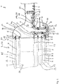
- FIG. 1 illustrates in a schematic, highly simplified representation of the structure of a charge air cooler 1 according to the invention for cooling the charge air to be introduced into the combustion chambers of an internal combustion engine.
- the charge air cooler 1 comprises a heat exchanger 2, which has a plurality of fluid paths 3 for flowing through with the charge air 5 to be cooled.
- the fluid paths 3 are part of the heat exchanger 2.
- the heat exchanger 2 may be designed in the manner of a stacked disk heat exchanger, which is flowed through by the charge air 5 and, fluidically separated from it, by a coolant (not shown).
- the fluid paths 3 through which the charge air can flow alternate along a stacking direction with coolant paths 7, through which the coolant can flow.
- the charge air 5 is cooled, so that after flowing through the intercooler 1 can be reintroduced into the combustion chambers of the internal combustion engine with reduced temperature. If the intercooler 1 is used in a motor vehicle, then the ambient air of the motor vehicle can be used as coolant, in which it is introduced as a wind into the intercooler 1 and discharged from it again.
- a tube-bundle heat exchanger 22 can also be used as the heat exchanger 2.
- the tube bundle heat exchanger 22 may be realized by a hollow cylinder 25 of a suitable material, typically of a metal, in the interior 26 of which a plurality of tubular bodies 23 are arranged.
- Said tubular bodies 23 form the fluid paths 3 through which charge air can flow.
- the complementary to these tubular bodies 23 part of the interior 26 forms one or more coolant paths 7 for flowing through the coolant.
- the tubular body 23 may be fixed to an end plate 24 of the heat exchanger 2.
- the more detailed structural design of the heat exchanger 2 or tube bundle heat exchanger 22 is not known core of the invention presented here and the relevant expert, so that is omitted at this point to more detailed explanations.
- a collector 9 mounted on the heat exchanger 2 and communicating with the fluid paths 3, which communicates fluidically with the fluid paths 3. In this way, the charge air 5 can be collected after flowing through the individual fluid paths 3 and introduced into the combustion chambers of the internal combustion engine.
- the collector 9 comprises a housing 16 which delimits a housing interior 19. A lower part of the housing 16 is formed by a housing bottom 17, which may be formed integrally on the housing 16.
- the intercooler 1 comprises a condensate receiving portion 4 of this condensate 6.
- FIG. 1 clearly shows the condensate receiving portion 4 is formed for receiving the condensed charge air 5 through a lower portion 7 of the collector 9.
- the condensate-receiving area 4 is bounded by the housing bottom 17 of the housing 16 of the collector 9 and is trough-shaped in the example scenario.
- a tubular body 8 is arranged in the housing interior 19, which limits a fluid channel 18.
- an opening 10 is present, which fluidly connects the fluid channel 18 with the condensate receiving area 4.
- the opening 10 is arranged within the condensate receiving area 4 in the tubular body 8. Through the opening 10 through the condensate 6 can get out of the condensate receiving area 4 in the tubular body 8.
- the tubular body 8 further has a tubular body inlet 11 and a tubular body outlet 12, which are both arranged above the aperture 10 in a position of use of the intercooler 1.
- the tubular body inlet 11 and the tubular body outlet 12 are both arranged outside the condensate receiving area 4.
- the existing condensate in the receiving area 4 condensate is doing as in FIG. 1 implied taken from the flowing through the tubular body 8 charge air 5 and transported out of the condensate receiving area 4 and thus also from the collector 9 in this way.
- the condensate 6 can be "entrained" as a liquid film, as a foam or in the form of plugs of the charge air.
- the tubular body 8 may be made of a metal or a plastic and by means of a releasable connection (in FIG. 1 not shown), for example by means of a clip or locking connection, be secured to the housing 16.
- the tubular body 8 can be realized with an inner diameter of 8 mm to 10 mm. Alternatively, however, it is also a one-piece design conceivable in which the tubular body 8 made of plastic integrally formed on the housing 16 made of plastic.
- the pipe body 8 sections a U-shaped geometry.
- the sectional U-shaped tubular body 8 comprises a base portion 13, which merges at its opposite ends into a first and a second leg portion 14a, 14b.
- the opening 10 is arranged in the base section 13.
- the opening 10 may be designed as a through hole, which has a diameter between 1 mm and 2mm.
- the tubular body inlet 11 is arranged in the first leg section 14a and the tubular body outlet 12 in the second leg section 14b.
- the second leg section 14b facing away from the heat exchanger 2 comprises an outlet section 20 which extends away from the base section in parallel to the fluid lines 3 of the heat exchanger extends.
- the tubular body outlet 12 is arranged in the outlet section 20.
- the tubular body inlet 11 is remote from the housing bottom 17.
- the aperture 10 is disposed in a portion of the base portion 13 of the U-shaped tubular body 8, which has a minimum distance from the housing bottom 17 of the housing 16.
- the opening 10 is facing the housing bottom 17.
- the existing in the heat exchanger 2 fluid paths 3 open via respective fluid path outlet openings 15 in the collector 9.
- the tubular body outlet 12 is oriented parallel to the fluid path outlet openings 15. In the example scenario, the tubular body inlet 11, the aperture 10, and the tubular body outlet 12 are each rotated by 90 ° to each other.
- the housing 16 of the collector 9 and the tubular body 8 may be formed in two parts.
- the tubular body by means of a clip or locking connection (in FIG. 1 not shown releasably secured to the housing 16.
- the tubular body 8 may also be formed integrally on the housing 16 of the collector 9.
- a single tubular body 8 is arranged in the collector 9, but at least two tubular bodies 8 having a respective opening 10 are stacked on top of each other.
- the at least two existing apertures 10-each tubular body 8 is provided with an opening 10 - at a distance from each other and at different distances to the condensate-receiving area 4 and the housing bottom 17 in the collector 9.
Abstract
Die Erfindung betrifft einen Ladeluftkühler (1) für eine Brennkraftmaschine. Der Ladeluftkühler (1) umfasst einen Wärmeübertrager (2), der mehrere Fluidpfade (3) zum Durchströmen mit der zu kühlenden Ladeluft (5) aufweist. Ferner umfasst der Ladeluftkühler (1) einen am Wärmeübertrager (2) angebrachten und mit den Fluidpfaden (3) kommunizierenden Sammler (9). Dabei ist ein unterer Bereich des Sammlers (9) als Kondensat-Aufnahmebereich (5) zum Aufnehmen von kondensierter Ladeluft (5) ausgebildet. Im Sammler (9) ist des Weiteren ein Rohrkörper (8) angeordnet, welcher einen sowohl von kondensierter als auch nichtkondensierter Ladeluft (5) durchströmbaren Fluidkanal (18) begrenzt. Im Rohrkörper (8) ist ein Durchbruch (10) ausgebildet, der den Fluidkanal (18) fluidisch mit dem Kondensat-Aufnahmebereich (4) verbindet.

Description
Die vorliegende Erfindung betrifft einen Ladeluftkühler, insbesondere für ein Kraftfahrzeug, insbesondere für eine Brennkraftmaschine sowie eine Brennkraftmaschine mit einem solchen Ladeluftkühler.The present invention relates to a charge air cooler, in particular for a motor vehicle, in particular for an internal combustion engine and an internal combustion engine with such a charge air cooler.
Aus der
Aus der
Die vorliegende Erfindung beschäftigt sich mit dem Problem, für einen Ladeluftkühler der gattungsgemäßen Art eine verbesserte oder zumindest alternative Ausführungsform anzugeben, die sich insbesondere durch eine verbesserte Abführung von kondensierter Ladeluft aus dem Ladeluftkühler auszeichnet.The present invention is concerned with the problem of providing for an intercooler of the generic type an improved or at least alternative embodiment, which is characterized in particular by an improved removal of condensed charge air from the intercooler.
Diese Aufgabe wird durch den Gegenstand der unabhängigen Patentansprüche gelöst. Bevorzugte Ausführungsformen sind Gegenstand der abhängigen Patentsprüche.This object is solved by the subject matter of the independent patent claims. Preferred embodiments are the subject of dependent patent claims.
Grundgedanke der Erfindung ist demnach, in einem Sammler des Ladeluftkühlers, in welchem die Ladeluft nach dem Durchströmen des Wärmeübertragers gesammelt wird, einen Kondensat-Aufnahmebereich zur Aufnahme von aus der Ladeluft ausfallendem Kondensat anzuordnen. Ein solcher Sammler ist dem Fachmann auch als "Luftsammelkasten" oder "Sammelkasten" bekannt.The basic idea of the invention is accordingly to arrange a condensate receiving area for receiving condensate precipitating from the charge air in a collector of the intercooler in which the charge air is collected after flowing through the heat exchanger. Such a collector is also known to the person skilled in the art as an "air collection box" or "collection box".
Da die Ladeluft im Wärmeübertrager durch Abführung von Wärme an ein Kühlmittel gekühlt wird, erfolgt die Kondensation von Teilen der Ladeluft typischerweise während des Durchströmens des Wärmeübertragers oder unmittelbar am Austritt aus dem Wärmeübertrager, also beim Eintritt in den stromab des Wärmeübertragers angeordneten Sammler.Since the charge air is cooled in the heat exchanger by dissipating heat to a coolant, the condensation of parts of the charge air typically takes place during the passage of the heat exchanger or directly at the outlet from the heat exchanger, ie when entering the collector arranged downstream of the heat exchanger.
Die Ausbildung eines Kondensat-Aufnahmebereichs in besagtem Sammler bewirkt einerseits, dass das Kondensat gezielt dort gesammelt wird, wo es auch ausfällt, also entsteht; andererseits wird für den Kondensat-Aufnahme-bereich kein zusätzlicher Bauraum benötigt, da dieser in den stromab des Wärmeübertragers angebrachten Sammler integriert ist.The formation of a condensate receiving area in said collector causes on the one hand, that the condensate is collected specifically where it also fails, so arises; On the other hand, no additional space is needed for the condensate-receiving area, since this is integrated in the collector mounted downstream of the heat exchanger.
Des Weiteren fußt die Erfindung auf dem Gedanken, im Sammler einen Rohrkörper anzuordnen, welcher einen sowohl vom Kondensat als auch der Ladeluft durchströmbaren Fluidkanal begrenzt. Dabei ist im Rohrkörper ein Durchbruch ausgebildet, der den Fluidkanal fluidisch mit dem Kondensat-Aufnahmebereich verbindet. Der Durchbruch befindet sich bevorzugt am tiefsten Punkt des Rohrkörpers, welcher besonders zweckmäßig als U-förmiger Rohrkörper ausgebildet sein kann.Furthermore, the invention is based on the idea of arranging a tubular body in the collector, which limits a fluid channel through which both the condensate and the charge air can flow. In this case, an opening is formed in the tubular body, which fluidly connects the fluid channel with the condensate receiving area. The breakthrough is preferably at the lowest point of the tubular body, which may be particularly useful as a U-shaped tubular body.
Auf diese Weise kann die durch den Rohrkörper strömende Ladeluft dazu verwendet werden, das im Kondensat-Aufnahmebereich angesammelte Kondensat quasi "mitzunehmen" und aus dem Kondensat-Aufnahmebereich abzuführen. Dies ist auch bei einer nur geringen Druckdifferenz des Ladeluft-Drucks zwischen dem Sammler und einem dem Ladeluftkühler typischerweise nachgeschalteten Ansaugkrümmer möglich. Im Ergebnis kann also beim erfindungsgemäßen Ladeluftkühler das ausgefallene Kondensat gezielt in einem Kondensat-Aufnahmebereich des Sammlers gesammelt und auch effektiv wieder aus diesem abgeführt werden, ohne dass hierfür eine aufwändig technische Konstruktion erforderlich wäre.In this way, the charge air flowing through the tubular body can be used to collect the condensate accumulated in the condensate receiving area quasi "take along" and dissipate from the condensate receiving area. This is possible even with only a small pressure difference of the charge air pressure between the collector and a charge air cooler typically downstream intake manifold. As a result, therefore, in the charge air cooler according to the invention, the precipitated condensate can be collected in a targeted manner in a condensate receiving region of the collector and effectively removed from it without this requiring a complex technical construction.
Ein erfindungsgemäßer Ladeluftkühler für eine Brennkraftmaschine umfasst einen Wärmeübertrager, der mehrere Fluidpfade zum Durchströmen mit der zu kühlenden Ladeluft aufweist. Am Wärmeübertrager ist ein Sammler angebracht, der mit den Fluidpfaden kommuniziert. Ein unterer Bereich des Sammlers ist als Kondensat-Aufnahmebereich zum Aufnehmen von ausgefallenem Kondensat der Ladeluft ausgebildet ist. Im Sammler ist zumindest ein Rohrkörper angeordnet, welcher einen sowohl vom Kondensat als auch der Ladeluft durchströmbaren Fluidkanal begrenzt. In dem zumindest einen Rohrkörper wiederum ist ein Durchbruch vorhanden, der den Fluidkanal fluidisch mit dem Kondensat-Aufnahmebereich verbindet.An intercooler according to the invention for an internal combustion engine comprises a heat exchanger which has a plurality of fluid paths for flowing through with the charge air to be cooled. At the heat exchanger, a collector is mounted, which communicates with the fluid paths. A lower portion of the collector is formed as a condensate receiving area for receiving failed condensate of the charge air. In the collector, at least one tubular body is arranged, which limits a flow channel through which both the condensate and the charge air can flow. In turn, an opening is present in the at least one tubular body, which fluidly connects the fluid channel to the condensate receiving area.
Bei einer bevorzugten Ausführungsform weist der Rohrkörper einen Rohrkörper-Einlass und einen Rohrkörper-Auslass auf, welche in einer Gebrauchslage des Ladeluftkühlers, insbesondere im Motorraum eines Kraftfahrzeugs, beide oberhalb des Durchbruchs angeordnet sind. Dies erlaubt eine effektive Einleitung von Ladeluft in den Rohrkörper.In a preferred embodiment, the tubular body has a tubular body inlet and a tubular body outlet, which are arranged in a position of use of the charge air cooler, in particular in the engine compartment of a motor vehicle, both above the opening. This allows an effective introduction of charge air into the tubular body.
Besonders bevorzugt ist der Durchbruch im Kondensat-Aufnahmebereich angeordnet, wohingegen der Rohrkörper-Einlass sowie der Rohrkörper-Auslass außerhalb des Kondensat-Aufnahmebereichs angeordnet sind. Auf diese Weise wird sichergestellt, dass nur Ladeluft über den Rohrkörper-Einlass in den Rohrkörper eingeleitet wird, dass nur Kondensat durch den Durchbruch in den Rohrkörper gelangt und dort von der Ladeluft mitgenommen wird, und dass Ladeluft und Kondensat zusammen wieder aus dem Rohrkörper austreten und den Sammler verlassen können.The breakthrough is particularly preferably arranged in the condensate receiving region, whereas the tubular body inlet and the tubular body outlet are arranged outside the condensate receiving region. In this way it is ensured that only charge air through the pipe body inlet into the pipe body is introduced, that only condensate passes through the opening in the tubular body and is taken there by the charge air, and that charge air and condensate together again emerge from the tubular body and can leave the collector.
Bei einer weiteren bevorzugten Ausführungsform besitzt der Rohrkörper wenigstens abschnittweise eine U-förmige Geometrie. Eine solche Geometrie erlaubt eine einfache Realisierung der o.g. vorteilhaften Anordnung von Rohrkörper-Einlass und -Auslass oberhalb des Durchbruchs.In a further preferred embodiment, the tubular body has at least in sections a U-shaped geometry. Such a geometry allows a simple realization of the o.g. advantageous arrangement of tubular body inlet and outlet above the aperture.
Zweckmäßig weist der wenigstens abschnittsweise U-förmige Rohrkörper einen Basisabschnitt auf, der an seinen gegenüberliegenden Enden, vorzugsweise integral, in einen ersten und einen zweiten Schenkelabschnitt übergeht. Bei dieser Variante ist der Durchbruch im Basisabschnitt angeordnet. Der Rohrkörper-Einlass ist im ersten Schenkelabschnitt, und der Rohrkörper-Auslass ist im zweiten Schenkelabschnitt angeordnet.Suitably, the at least partially U-shaped tubular body has a base portion, which merges at its opposite ends, preferably integrally, in a first and a second leg portion. In this variant, the breakthrough is arranged in the base section. The tubular body inlet is in the first leg portion, and the tubular body outlet is disposed in the second leg portion.
Bei einer weiteren bevorzugten Ausführungsform umfasst der vom Wärmeübertrager abgewandte zweite Schenkelabschnitt einen Austrittsabschnitt. Besagter Austrittsabschnitt erstreckt sich vom Basisabschnitt weg parallel zu den Fluidleitungen des Wärmeübertragers. Hierbei ist der Rohrkörper-Auslass des Rohrkörpers im Austrittsabschnitt angeordnet. Mittels des Austrittsabschnitts kann sichergestellt werden, dass das aus dem Rohrkörper ausgeleitete Kondensat nicht wieder zurück in den Kondensat-Aufnahmebereich gelangen kann.In a further preferred embodiment, the second leg section facing away from the heat exchanger comprises an exit section. Said outlet portion extends away from the base portion parallel to the fluid lines of the heat exchanger. Here, the tubular body outlet of the tubular body is arranged in the outlet section. By means of the outlet section, it can be ensured that the condensate discharged from the tubular body can not be returned to the condensate receiving area.
Bei einer vorteilhaften Weiterbildung umfasst der Sammler ein Gehäuse, welches einen Gehäuseinnenraum begrenzt. Bei dieser Weiterbildung ist der Kondensat-Aufnahmebereich Teil des Gehäuseinnenraums und von einem wannenförmig ausgebildeten Gehäuseboden begrenzt, welcher wiederum Teil des Gehäuses ist. Diese Variante ist mit besonders geringen Fertigungskosten verbunden.In an advantageous development of the collector comprises a housing which limits a housing interior. In this development, the condensate receiving area is part of the housing interior and of a trough-shaped limited trained housing bottom, which in turn is part of the housing. This variant is associated with very low production costs.
Besonders bevorzugt ist der Durchbruch in einem Bereich des Basisabschnitts angeordnet, der von einem den Sammler begrenzenden Gehäuseboden einen minimalen Abstand besitzt. Auf diese Weise wird sichergestellt, dass auch bei einer geringen Menge an im Kondensat-Aufnahmebereich angesammeltem Kondensat dieses über den Durchbruch in den Rohrkörper gelangen kann.Particularly preferably, the opening is arranged in a region of the base section which has a minimum distance from a housing bottom bounding the collector. In this way it is ensured that even with a small amount of accumulated condensate in the condensate receiving area this can get over the breakthrough in the tube body.
Alternativ oder zusätzlich kann der Durchbruch dem Gehäuseboden zugewandt sein. Auch diese Maßnahme gewährleistet, dass bei einer nur geringen Menge an im Kondensat-Aufnahmebereich angesammeltem Kondensat dieses über den Durchbruch in den Rohrkörper gelangen kann.Alternatively or additionally, the opening may face the housing bottom. This measure also ensures that, with only a small amount of condensate accumulated in the condensate receiving area, this can pass through the breakthrough into the tubular body.
Besonders bevorzugt ist der Rohrkörper-Einlass vom Gehäuseboden abgewandt. Dies erlaubt eine effektive Einleitung von aus dem Wärmeübertrager austretender, nicht-kondensierter Ladeluft in den Rohrkörper.Particularly preferably, the tubular body inlet is remote from the housing bottom. This allows an effective introduction of emerging from the heat exchanger, non-condensed charge air in the tubular body.
Besonders zweckmäßig münden die im Wärmeübertrager vorhandenen Fluidpfade über jeweilige Fluidpfad-Austrittsöffnungen in den Sammler. Bei dieser Variante ist der Rohrkörper-Auslass parallel zu den Fluidpfad-Austrittsöffnungen orientiert. Dies erlaubt eine effektive Abführung des Kondensats aus dem Sammler nach dem Austritt aus dem Rohrkörper, und zwar mit Hilfe der außerhalb des Rohrkörpers durch den Sammler strömenden Ladeluft.Particularly expediently, the fluid paths present in the heat exchanger open via respective fluid path outlet openings into the collector. In this variant, the tubular body outlet is oriented parallel to the fluid path outlet openings. This allows effective removal of the condensate from the collector after exiting the tubular body, with the aid of the charge air flowing outside of the tubular body through the collector.
Bei einer vorteilhaften Weiterbildung sind der Rohrkörper-Einlass, der Durchbruch, und der Rohrkörper-Auslass jeweils um 90° verdreht zueinander orientiert. Eine besonders flexible Montage und Demontage des Rohrkörpers am Sammler erlaubt eine weitere bevorzugte Ausführungsform, bei welcher das Gehäuse des Sammlers und der Rohrkörper zweiteilig ausgebildet sind. Bei dieser Variante ist der Rohrkörper lösbar am Gehäuse befestigt, was vorzugsweise mit Hilfe vorzugsweise einer Clip- oder Rastverbindung realisiert sein kann.,In an advantageous embodiment of the tubular body inlet, the breakthrough, and the tubular body outlet are each rotated by 90 ° to each other. A particularly flexible assembly and disassembly of the tubular body on the collector allows a further preferred embodiment in which the housing of the collector and the tubular body are formed in two parts. In this variant, the tubular body is releasably secured to the housing, which may preferably be realized by means of preferably a clip or latching connection.
Mit besonders geringen Herstellungskosten ist indes eine weitere bevorzugte Ausführungsform verbunden, bei welcher der Rohrkörper integral am Gehäuse des Sammlers ausgeformt ist.With particularly low production costs, however, a further preferred embodiment is connected, in which the tubular body is integrally formed on the housing of the collector.
Bei einer weiteren bevorzugten Ausführungsform sind im Sammler zumindest zwei einen jeweiligen Durchbruch aufweisende Rohrkörper aufeinandergestapelt oder übereinander angeordnet. Die wenigstens zwei Rohrkörper können im Abstand zueinander angeordnet sein oder aneinander anliegen. Bei dieser Variante sind die wenigstens zwei vorhandenen Durchbrüche im Abstand zueinander und mit unterschiedlichem Abstand zum Kondensat-Aufnahmebereich im Sammler angeordnet. Ist der Flüssigkeitsspiegel aus dem Kondensat im untersten Rohrkörper so hoch, dass der Druck der Flüssigkeitssäule über dem Durchbruch größer ist als der zur Verfügung stehende Druckabfall zwischen Einlass und Auslass des Rohres, dann ist der unterste Rohrkörper blockiert und kann keine Flüssigkeit mehr fördern. Bei der hier vorgeschlagenen Ausführungsform kann der Abtransport des Kondensates durch wenigstens einen höher angeordneten Rohrkörper aufrecht erhalten werden, welcher bei niedrigem Flüssigkeitsspiegel keine Flüssigkeit fördert, da er nicht in das Kondensat eintaucht. Auf diese Weise kann die gewünschte Wirkung des Rohrkörpers auch stark schwankendem Flüssigkeitsspiegel, beispielsweise durch schwallartig anfallendes Kondensat, gewährleistet werden.In a further preferred embodiment, at least two tube bodies having a respective breakthrough are stacked in the collector or arranged one above the other. The at least two tubular bodies can be arranged at a distance from one another or rest against one another. In this variant, the at least two existing openings at a distance from each other and arranged at different distances to the condensate-receiving area in the collector. If the liquid level from the condensate in the lowermost tubular body is so high that the pressure of the liquid column above the breakthrough is greater than the available pressure drop between the inlet and outlet of the tube, then the lowermost tubular body is blocked and can no longer convey liquid. In the embodiment proposed here, the removal of the condensate can be maintained by at least one higher-positioned tubular body, which promotes no liquid at a low liquid level, since it does not dive into the condensate. In this way, the desired effect of the tubular body and strongly fluctuating liquid level, for example by bubbling accumulating condensate, can be ensured.
Die Erfindung betrifft ferner eine Brennkraftmaschine mit einer Abgasanlage und mit einem vorangehend vorgestellten Ladeluftkühler. Die vorangehend erläuterten Vorteile des erfindungsgemäßen Ladeluftkühlers übertragen sich daher auch auf die Brennkraftmaschine.The invention further relates to an internal combustion engine with an exhaust system and with a previously presented intercooler. The above-explained advantages of the charge air cooler according to the invention therefore also be transferred to the internal combustion engine.
Weitere wichtige Merkmale und Vorteile der Erfindung ergeben sich aus den Unteransprüchen, aus den Zeichnungen und aus der zugehörigen Figurenbeschreibung anhand der Zeichnung.Other important features and advantages of the invention will become apparent from the dependent claims, from the drawings and from the associated figure description with reference to the drawing.
Es versteht sich, dass die vorstehend genannten und die nachstehend noch zu erläuternden Merkmale nicht nur in der jeweils angegebenen Kombination, sondern auch in anderen Kombinationen oder in Alleinstellung verwendbar sind, ohne den Rahmen der vorliegenden Erfindung zu verlassen.It is understood that the features mentioned above and those yet to be explained below can be used not only in the particular combination given, but also in other combinations or in isolation, without departing from the scope of the present invention.
Bevorzugte Ausführungsbeispiele der Erfindung sind in der Zeichnung dargestellt und werden in der nachfolgenden Beschreibung näher erläutert.Preferred embodiments of the invention are illustrated in the drawings and will be explained in more detail in the following description.
Die einzige
Alternativ zum Stapelscheibenwärmetauscher kann als Wärmeübertrager 2 auch ein Rohrbündel-Wärmetauscher 22 eingesetzt werden. Technisch kann der Rohrbündel-Wärmetauscher 22 durch einen Hohlzylinder 25 aus einem geeigneten Material, typischerweise aus einem Metall, realisiert sein, in dessen Innenraum 26 sich eine Mehrzahl von Rohrkörpern 23 angeordnet befinden. Alternativ zur Geometrie eines Hohlzylinders 25 sind auch andere geeignete Geometrien denkbar. Besagte Rohrkörper 23 bilden die von Ladeluft durchströmbaren Fluidpfade 3 aus. Der zu diesen Rohrkörpern 23 komplementäre Teil des Innenraums 26 bildet einen oder mehrere Kühlmittelpfade 7 zum Durchströmen mit dem Kühlmittel. Die Rohrkörper 23 können an einer Endplatte 24 des Wärmeübertragers 2 fixiert sein.As an alternative to the stacked-plate heat exchanger, a tube-bundle heat exchanger 22 can also be used as the
Der genauere konstruktive Aufbau des Wärmeübertragers 2 bzw. RohrbündelWärmetauschers 22 ist nicht Kern der hier vorgestellten Erfindung und dem einschlägigen Fachmann bekannt, so dass an dieser Stelle auf detailliertere Erläuterungen verzichtet wird. Für die vorliegende Erfindung relevant ist jedoch ein am Wärmeübertrager 2 angebrachter und mit den Fluidpfaden 3 kommunizierender Sammler 9, der fluidisch mit den Fluidpfaden 3 kommuniziert. Auf diese Weise kann die Ladeluft 5 nach dem Durchströmen der einzelnen Fluidpfade 3 gesammelt und in die Brennkammern der Brennkraftmaschine eingeleitet werden. Der Sammler 9 umfasst ein Gehäuse 16, welches einen Gehäuseinnenraum 19 begrenzt. Ein unterer Teil des Gehäuses 16 wird durch einen Gehäuseboden 17 gebildet, der integral am Gehäuse 16 ausgeformt sein kann.The more detailed structural design of the
Im Zuge der Kühlung der Ladeluft 5 im Wärmeübertrager 2 kann ein Teil der gasförmigen Ladeluft auskondensieren und als Kondensat 6 im Ladeluftkühler 1 ausfallen. Hierfür umfasst der Ladeluftkühler 1 einen Kondensat-Aufnahmebereich 4 dieses Kondensats 6. Wie
Zur Abführung des im Kondensat-Aufnahmebereich 4 angesammelten Kondensats 6 aus dem Sammler 9 ist im Gehäuseinnenraum 19 ein Rohrkörper 8 angeordnet, welcher einen Fluidkanal 18 begrenzt. Im Rohrkörper 8 ist ein Durchbruch 10 vorhanden, der den Fluidkanal 18 fluidisch mit dem Kondensat-Aufnahmebereich 4 verbindet. Der Durchbruch 10 ist innerhalb des Kondensat-Aufnahmebereichs 4 im Rohrkörper 8 angeordnet. Durch den Durchbruch 10 hindurch kann das Kondensat 6 aus dem Kondensat-Aufnahmebereich 4 in den Rohrkörper 8 gelangen.For discharging the accumulated condensate in the receiving
Der Rohrkörper 8 weist ferner einen Rohrkörper-Einlass 11 und einen Rohrkörper-Auslass 12 auf, welche in einer Gebrauchslage des Ladeluftkühlers 1 beide oberhalb des Durchbruchs 10 angeordnet sind. Der Rohrkörper-Einlass 11 sowie der Rohrkörper-Auslass 12 sind beide außerhalb des Kondensat-Aufnahmebereichs 4 angeordnet. Somit kann auch aus dem Wärmeübertrager 2 ausgetretene, nicht kondensierte Ladeluft 5 in den Rohrkörper gelangen, den Rohrkörper 8 durchströmen und wieder aus diesem austreten. Das im Kondensat-Aufnahmebereich 4 vorhandene Kondensat wird dabei wie in
Nach dem Verlassen des Rohrkörpers 8 durch den Rohrkörper-Auslass 12 können Ladeluft 5 und Kondensat 6 zusammen mit der nicht durch den Rohrkörper 8 geführten Ladeluft durch einen im Gehäuse 16 des Sammlers 9 vorgesehenen Sammler-Auslass 21 aus dem Sammler 9 ausgeleitet werden. Der Rohrkörper 8 kann aus einem Metall oder aus einem Kunststoff hergestellt sein und mittels einer lösbaren Verbindung (in
Als Gebrauchslage wird im Beispielszenario die Einbauorientierung des Ladeluftkühlers 1 im Motorraum eines Kraftfahrzeugs verstanden.As a position of use is understood in the example scenario, the installation orientation of the charge air cooler 1 in the engine compartment of a motor vehicle.
Wie
Wie
Die im Wärmeübertrager 2 vorhandenen Fluidpfade 3 münden über jeweilige Fluidpfad-Austrittsöffnungen 15 in den Sammler 9. Der Rohrkörper-Auslass 12 ist parallel zu den Fluidpfad-Austrittsöffnungen 15 orientiert. Im Beispielszenario sind der Rohrkörper-Einlass 11, der Durchbruch 10, und der Rohrkörper-Auslass 12 jeweils um 90° verdreht zueinander orientiert.The existing in the
Das Gehäuse 16 des Sammlers 9 und der Rohrkörper 8 können zweiteilig ausgebildet sein. Bei dieser Variante kann der Rohrkörper mittels einer Clip- oder Rastverbindung (in
Bei einer Weiterbildung ist nicht nur ein einziger Rohrkörper 8 im Sammler 9 angeordnet, sondern es sind zumindest zwei einen jeweiligen Durchbruch 10 aufweisende Rohrkörper 8 aufeinandergestapelt. Bei dieser Variante sind die wenigstens zwei vorhandenen Durchbrüche 10-jeder Rohrkörper 8 ist mit einem Durchbruch 10 ausgestattet - im Abstand zueinander und mit unterschiedlichem Abstand zum Kondensat-Aufnahmebereich 4 bzw. zum Gehäuseboden 17 im Sammler 9 angeordnet. Ist der Flüssigkeitsspiegel aus dem Kondensat 6 im untersten, also dem Kondensat-Aufnahmebereich 4 bzw. dem Gehäuseboden 17 nächstgelegensten Rohrkörper 8 so hoch, dass der Druck der Flüssigkeitssäule des Kondensats 6 über dem Durchbruch 10 größer ist als der zur Verfügung stehende Druckabfall zwischen Rohrkörper-Einlass 11 und Rohrkörper-Auslass 13 des Rohrkörpers 8, so ist der unterste Rohrkörper 8 blockiert und kann kein Kondensat 6 fördern. Bei der Weiterbildung mit zumindest zwei Rohrkörpern 8 hingegen kann der Abtransport des Kondensates 6 durch wenigstens einen höher angeordneten Rohrkörper 8 aufrecht erhalten werden, welcher bei niedrigem Flüssigkeitsspiegel keine Flüssigkeit fördert, da er nicht in das Kondensat 6 eintaucht. Ein solcher weiterer Rohrkörper 8 ist in
Claims (16)
dadurch gekennzeichnet, dass
der Rohrkörper (8) einen Rohrkörper-Einlass (11) und einen Rohrkörper-Auslass (12) aufweist, welche in einer Gebrauchslage des Ladeluftkühlers (1) beide oberhalb des Durchbruchs (10) angeordnet sind.Intercooler according to claim 1,
characterized in that
the tubular body (8) has a tubular body inlet (11) and a tubular body outlet (12), which are both arranged above the aperture (10) in a position of use of the charge air cooler (1).
dadurch gekennzeichnet, dass
der Durchbruch (10) im Kondensat-Aufnahmebereich (4) angeordnet ist und der Rohrkörper-Einlass (11) sowie der Rohrkörper-Auslass (12) außerhalb des Kondensat-Aufnahmebereichs (4) angeordnet sind.Intercooler according to claim 1 or 2,
characterized in that
the aperture (10) in the condensate receiving area (4) is arranged and the tubular body inlet (11) and the tubular body outlet (12) are arranged outside of the condensate receiving area (4).
dadurch gekennzeichnet, dass
der Rohrkörper (8) wenigstens abschnittweise eine U-förmige Geometrie besitzt.Intercooler according to one of claims 1 to 3,
characterized in that
the tubular body (8) at least in sections has a U-shaped geometry.
dadurch gekennzeichnet, dass
der wenigstens abschnittsweise U-förmige Rohrkörper (8) einen Basisabschnitt (13) aufweist, der an seinen gegenüberliegenden Enden in einen ersten und einen zweiten Schenkelabschnitt (14a, 14b) übergeht,
wobei der Durchbruch (10) im Basisabschnitt (13) angeordnet ist und der Rohrkörper-Einlass (11) im ersten Schenkelabschnitt (14a) angeordnet ist und der Rohrkörper-Auslass (12) im zweiten Schenkelabschnitt (14b) angeordnet ist.Intercooler according to claim 4,
characterized in that
the at least partially U-shaped tubular body (8) has a base portion (13) which merges at its opposite ends into a first and a second leg portion (14a, 14b),
wherein the aperture (10) is disposed in the base portion (13) and the tubular body inlet (11) is disposed in the first leg portion (14a) and the tubular body outlet (12) is disposed in the second leg portion (14b).
dadurch gekennzeichnet, dass
der vom Wärmeübertrager (2) abgewandte zweite Schenkelabschnitt (14b) einen Austrittsabschnitt (20) umfasst, der sich vom Basisabschnitt weg parallel zu den Fluidleitungen (3) des Wärmeübertragers (2) erstreckt und in welchem der Rohrkörper-Auslass (12) vorgesehen ist.Intercooler according to claim 5,
characterized in that
the second leg portion (14b) remote from the heat exchanger (2) comprises an exit portion (20) extending parallel to the fluid conduits (3) of the heat exchanger (2) away from the base portion and in which the tubular body outlet (12) is provided.
dadurch gekennzeichnet, dass
characterized in that
dadurch gekennzeichnet, dass
der Durchbruch (10) in einem Bereich des Basisabschnitts (13) des Rohrkörpers (8) angeordnet ist, der von dem den Kondensat-Aufnahmebereich (4) begrenzenden Gehäuseboden (17) einen minimalen Abstand besitzt.Intercooler according to claim 7,
characterized in that
the aperture (10) is arranged in a region of the base portion (13) of the tubular body (8) which has a minimum distance from the housing bottom (17) delimiting the condensate receiving region (4).
dadurch gekennzeichnet, dass
der Durchbruch (10) dem Gehäuseboden (17) zugewandt ist.Intercooler according to one of claims 6 to 8,
characterized in that
the aperture (10) faces the housing bottom (17).
dadurch gekennzeichnet, dass
der Rohrkörper-Einlass (11) vom Gehäuseboden (17) abgewandt ist.Intercooler according to one of claims 5 to 9,
characterized in that
the tubular body inlet (11) facing away from the housing bottom (17).
dadurch gekennzeichnet, dass
die im Wärmeübertrager (2) vorhandenen Fluidpfade (3) über jeweilige Fluidpfad-Austrittsöffnungen (15) in den Sammler (9) münden und der Rohrkörper-Auslass (12) parallel zu den Fluidpfad-Austrittsöffnungen (15) orientiert ist.Intercooler according to one of claims 5 to 10,
characterized in that
the fluid paths (3) present in the heat exchanger (2) open into the collector (9) via respective fluid path outlet openings (15) and the tube body outlet (12) is oriented parallel to the fluid path outlet openings (15).
dadurch gekennzeichnet, dass
der Rohrkörper-Einlass (11) und der im Rohrkörper (8) ausgebildete Durchbruch (10) und der Rohrkörper-Auslass (12) jeweils um 90° verdreht zueinander orientiert sind.Intercooler according to one of claims 5 to 11,
characterized in that
the tubular body inlet (11) and the opening (10) formed in the tubular body (8) and the tubular body outlet (12) are each oriented at 90 ° to each other.
dadurch gekennzeichnet, dass
das Gehäuse (16) des Sammlers (9) und der Rohrkörper (8) zweiteilig ausgebildet sind und dass der Rohrkörper (8), vorzugsweise mittels einer Clip- oder Rastverbindung, lösbar am Gehäuse (16) befestigt ist.Intercooler according to one of claims 7 to 12,
characterized in that
the housing (16) of the collector (9) and the tubular body (8) are formed in two parts and that the tubular body (8), preferably by means of a clip or latching connection, releasably secured to the housing (16).
dadurch gekennzeichnet, dass
der Rohrkörper (8) integral am Gehäuse (16) des Sammlers (9) ausgeformt ist.Intercooler according to one of claims 7 to 12,
characterized in that
the tubular body (8) is formed integrally on the housing (16) of the collector (9).
dadurch gekennzeichnet, dass
im Sammler (9) zumindest zwei einen jeweiligen Durchbruch (10) aufweisende Rohrkörper (8) aufeinandergestapelt sind, so dass die wenigstens zwei Durchbrüche (10) im Abstand zueinander und mit unterschiedlichem Abstand zum Kondensat-Aufnahmebereich (4) im Sammler (9) angeordnet sind.Intercooler according to one of the preceding claims,
characterized in that
in the collector (9) at least two a respective opening (10) having tubular body (8) are stacked, so that the at least two openings (10) at a distance from each other and at different distances to the condensate receiving area (4) arranged in the collector (9) are.
Applications Claiming Priority (1)
| Application Number | Priority Date | Filing Date | Title |
|---|---|---|---|
| DE102016214886.9A DE102016214886A1 (en) | 2016-08-10 | 2016-08-10 | Intercooler, in particular for a motor vehicle |
Publications (1)
| Publication Number | Publication Date |
|---|---|
| EP3282108A1 true EP3282108A1 (en) | 2018-02-14 |
Family
ID=59383996
Family Applications (1)
| Application Number | Title | Priority Date | Filing Date |
|---|---|---|---|
| EP17182342.0A Pending EP3282108A1 (en) | 2016-08-10 | 2017-07-20 | Charge air cooler, in particular for a motor vehicle |
Country Status (5)
| Country | Link |
|---|---|
| US (1) | US20180045102A1 (en) |
| EP (1) | EP3282108A1 (en) |
| KR (1) | KR20180018399A (en) |
| CN (1) | CN107725170A (en) |
| DE (1) | DE102016214886A1 (en) |
Families Citing this family (2)
| Publication number | Priority date | Publication date | Assignee | Title |
|---|---|---|---|---|
| US11333438B2 (en) * | 2018-06-26 | 2022-05-17 | Hamilton Sundstrand Corporation | Heat exchanger with water extraction |
| DE102022124283A1 (en) | 2022-09-21 | 2024-03-21 | Man Truck & Bus Se | Pipe construction, exhaust system having a pipe structure and vehicle having an exhaust system or a pipe structure |
Citations (4)
| Publication number | Priority date | Publication date | Assignee | Title |
|---|---|---|---|---|
| JP2005226476A (en) * | 2004-02-10 | 2005-08-25 | Toyota Motor Corp | Discharge structure of oil accumulated in air intake passage |
| FR2908505A1 (en) * | 2006-11-14 | 2008-05-16 | Renault Sas | Heat exchanger e.g. air-air type heat exchanger, for turbocharged/supercharged internal combustion engine of motor vehicle, has automatic drain device i.e. drain valve screw, draining impurities i.e. oil, in exchanger, by aspiration |
| DE102009022986A1 (en) * | 2009-05-28 | 2010-12-02 | Behr Gmbh & Co. Kg | Heat exchanger |
| US20140060500A1 (en) * | 2012-08-28 | 2014-03-06 | Ford Global Technologies, Llc | Charge air cooler with dual flow path conduit |
Family Cites Families (9)
| Publication number | Priority date | Publication date | Assignee | Title |
|---|---|---|---|---|
| DE3601391A1 (en) * | 1986-01-18 | 1987-02-26 | Daimler Benz Ag | Device for the suction removal of oil condensate dripping off into the air collecting box of a charge air cooler |
| FR2922962B1 (en) * | 2007-10-24 | 2014-04-18 | Valeo Systemes Thermiques | DEVICE FOR RECOVERING AND DISCHARGING PRODUCTS FOR CONDENSING AN INTAKE AIR FLOW |
| US8061135B2 (en) | 2008-03-07 | 2011-11-22 | GM Global Technology Operations LLC | Condensate extractor for charge air cooler systems |
| US7980076B2 (en) | 2008-09-30 | 2011-07-19 | GM Global Technology Operations LLC | Controlled condensate collection and evacuation for charge air cooler |
| US9010112B2 (en) * | 2009-10-27 | 2015-04-21 | Ford Global Technologies, Llc | Condensation trap for charge air cooler |
| US9027341B2 (en) * | 2011-07-18 | 2015-05-12 | Ford Global Technologies, Llc | System for a charge-air-cooler |
| DE102012219796A1 (en) * | 2012-10-30 | 2014-04-30 | Bayerische Motoren Werke Aktiengesellschaft | Device for supplying charge air for internal combustion engine, has suction tube arranged with end in condensate collecting area and with opposite end in injection section of connecting pipe for supplying condensate |
| JP6185349B2 (en) * | 2013-09-24 | 2017-08-23 | トヨタ自動車株式会社 | Intake gas cooling device for supercharged internal combustion engine |
| DE102014013502B4 (en) * | 2014-09-11 | 2023-05-11 | Man Truck & Bus Se | Intercooler arrangement with condensate extraction and swiveling intercooler |
-
2016
- 2016-08-10 DE DE102016214886.9A patent/DE102016214886A1/en not_active Withdrawn
-
2017
- 2017-07-20 EP EP17182342.0A patent/EP3282108A1/en active Pending
- 2017-08-03 CN CN201710654626.8A patent/CN107725170A/en active Pending
- 2017-08-09 US US15/673,375 patent/US20180045102A1/en not_active Abandoned
- 2017-08-09 KR KR1020170101066A patent/KR20180018399A/en unknown
Patent Citations (4)
| Publication number | Priority date | Publication date | Assignee | Title |
|---|---|---|---|---|
| JP2005226476A (en) * | 2004-02-10 | 2005-08-25 | Toyota Motor Corp | Discharge structure of oil accumulated in air intake passage |
| FR2908505A1 (en) * | 2006-11-14 | 2008-05-16 | Renault Sas | Heat exchanger e.g. air-air type heat exchanger, for turbocharged/supercharged internal combustion engine of motor vehicle, has automatic drain device i.e. drain valve screw, draining impurities i.e. oil, in exchanger, by aspiration |
| DE102009022986A1 (en) * | 2009-05-28 | 2010-12-02 | Behr Gmbh & Co. Kg | Heat exchanger |
| US20140060500A1 (en) * | 2012-08-28 | 2014-03-06 | Ford Global Technologies, Llc | Charge air cooler with dual flow path conduit |
Also Published As
| Publication number | Publication date |
|---|---|
| KR20180018399A (en) | 2018-02-21 |
| US20180045102A1 (en) | 2018-02-15 |
| DE102016214886A1 (en) | 2018-02-15 |
| CN107725170A (en) | 2018-02-23 |
Similar Documents
| Publication | Publication Date | Title |
|---|---|---|
| EP3163242B1 (en) | Indirect charge-air cooler | |
| DE102012006346A1 (en) | heat exchangers | |
| DE102014202447A1 (en) | Exhaust gas heat exchanger | |
| EP2170485B1 (en) | Separator | |
| EP1657512B2 (en) | Heat exchanger with open profile as housing | |
| EP2466089B1 (en) | Charge air cooler | |
| EP3282108A1 (en) | Charge air cooler, in particular for a motor vehicle | |
| DE102020110775A1 (en) | Ventilation device | |
| EP2481899A1 (en) | Heat exchanger | |
| DE10322165B4 (en) | Refrigerant-cooling heat exchanger | |
| DE102008020609A1 (en) | Heat exchangers, in particular oil coolers | |
| DE102018222815A1 (en) | Receiving box for a heat exchanger | |
| DE102016002380B4 (en) | Motor vehicle with an exhaust gas condenser | |
| DE102016213932A1 (en) | Intercooler, in particular for a motor vehicle | |
| DE102014212906A1 (en) | Intercooler with a plate heat exchanger | |
| EP3239641A1 (en) | Flat tube for a heat exchanger | |
| DE202019101397U1 (en) | exhaust gas cooler | |
| DE102017218254A1 (en) | Exhaust gas heat exchanger | |
| DE102018220142A1 (en) | Collecting pipe for a heat exchanger | |
| DE102018113339A1 (en) | Battery cooling device for cooling a battery, in particular the battery of a motor vehicle or arrangement structure with at least one battery, in particular a battery of a motor vehicle and with the aforementioned battery cooling device | |
| DE102017218122A1 (en) | Heat exchanger, in particular battery cooler, for controlling the temperature of battery modules of a motor vehicle | |
| DE102009050886A1 (en) | evaporator module | |
| EP3203173A1 (en) | Exhaust gas heat exchanger | |
| DE102016214086A1 (en) | Heat exchanger | |
| DE102017211927A1 (en) | Intercooler for an internal combustion engine |
Legal Events
| Date | Code | Title | Description |
|---|---|---|---|
| PUAI | Public reference made under article 153(3) epc to a published international application that has entered the european phase |
Free format text: ORIGINAL CODE: 0009012 |
|
| AK | Designated contracting states |
Kind code of ref document: A1 Designated state(s): AL AT BE BG CH CY CZ DE DK EE ES FI FR GB GR HR HU IE IS IT LI LT LU LV MC MK MT NL NO PL PT RO RS SE SI SK SM TR |
|
| AX | Request for extension of the european patent |
Extension state: BA ME |
|
| STAA | Information on the status of an ep patent application or granted ep patent |
Free format text: STATUS: REQUEST FOR EXAMINATION WAS MADE |
|
| 17P | Request for examination filed |
Effective date: 20180802 |
|
| RBV | Designated contracting states (corrected) |
Designated state(s): AL AT BE BG CH CY CZ DE DK EE ES FI FR GB GR HR HU IE IS IT LI LT LU LV MC MK MT NL NO PL PT RO RS SE SI SK SM TR |